Article

Effects of Shear Characteristics of Anchoring Interface on Bearing Performance of Fully Grouted Bolts Based on Variable Controlling Method

1
School of Mining Engineering, Taiyuan University of Technology, Taiyuan 030024, China
2
Key Laboratory of Shanxi Province for Mine Rock Strata Control and Disaster Prevention, Taiyuan 030024, China
3
Shanxi Province Coal-Based Resources Green and High-Efficiency Development Engineering Center, Taiyuan 030024, China
4
Shandong Taifeng Holding Group Co., Ltd., Xintai 271200, China
5
China Shanxi-Zheda Institute of Advanced Materials and Chemical Engineering, Taiyuan 030024, China
6
Centre for Infrastructural Monitoring and Protection, School of Civil and Mechanical Engineering, Curtin University, Bentley, WA 6102, Australia
*
Authors to whom correspondence should be addressed.
Buildings 2024, 14(4), 874; https://doi.org/10.3390/buildings14040874
Submission received: 12 January 2024 / Revised: 28 January 2024 / Accepted: 21 March 2024 / Published: 23 March 2024
(This article belongs to the Section Building Energy, Physics, Environment, and Systems)

Abstract

:
The shear strength parameter of an anchoring interface is one of the key parameters affecting the design of bolt support. To better realize the design of bolt support, the pullout model of fully grouted bolts was established by FLAC3D numerical software. The commonly used tri-linear bond-slip model of the anchoring interface was selected. The variable controlling method was used to investigate the effects of the shear strength parameters of the anchoring interface on the bearing performance of fully grouted bolts. The results show that, with the increase in the displacement at the peak shear stress, the bearing capacity and the energy absorption of fully grouted bolts decrease and the ability of the fully grouted anchoring system to resist external loads weakens. Meanwhile, the deformation capacity of fully grouted bolts increases, and the durability of the fully grouted anchoring system is enhanced. With the increase in the residual shear stress and the displacement at the residual shear stress, the bearing capacity and deformation capacity of fully grouted bolts both increase, and the energy absorption also increases. Increasing the post-peak bearing properties of the anchoring interface can help improve the bearing performance of fully grouted bolts and enhance the ability of the fully grouted bolts to resist failure. The results may provide guidance for support design and performance enhancement of fully grouted bolts.

1. Introduction

Coal resources are the stabilizer and ballast stone for China’s economic development, and roadway safety is the key to ensuring the safe and sustainable mining of coal resources [1]. A fully grouted bolt is an economical, fast and effective rock reinforcement technique, which has been widely used in coal mine roadway surrounding rock control [2]. Generally, the bolt is bonded to the rock by resin grout, and the bolt is usually under tension [3]. The pullout bearing performance of the bolt directly affects the supporting effect of the roadway [4]. Therefore, a better understanding of the pullout bearing performance of fully grouted bolts is critical for the design of bolt supports.
Fully grouted bolts are a typical Continuous Mechanically Coupled (CMC) system [5]. The pullout capacity of fully grouted bolts depends on the shear behavior of the anchoring interface [6]. In recent years, many studies have been conducted to investigate the pullout bearing performance of fully grouted bolts. Benmokrane et al. [7] proposed a tri-linear bond-slip model by experiments to describe the shear behavior of the anchoring interface. Wu et al. [8,9,10,11], Ren et al. [12], Martín et al. [13], Yan et al. [14,15], Cao et al. [16] and Chen et al. [17] analyzed the pullout bearing capacity and force evolution characteristics of fully grouted bolts using a tri-linear bond-slip model. Lu et al. [18,19] and Wu et al. [20,21] analyzed the mechanical response of fully grouted bolts during the whole pullout process by adopting an improved tri-linear bond-slip model. Chang et al. [22,23] and Ma et al. [24] numerically realized the tri-linear bond-slip model of the anchoring interface and studied the pullout bearing capacity and force characteristics of fully grouted bolts. You et al. [25] established a shear lag-debonding mechanical model of the anchoring interface, according to pullout tests. Cai et al. [26], He et al. [27], Xu et al. [28], Zhao et al. [29] and Duan et al. [30] analyzed the pullout bearing capacity and force characteristics of fully grouted bolts based on an improved shear lag-debonding model. Zhang et al. [31] established a hyperbolic model for load transfer at the anchoring interface. Zhou et al. [32] and Ma et al. [33] analyzed the pullout bearing characteristics of fully grouted bolts based on a hyperbolic model. Ma et al. [34,35] and Li et al. [36] realized the hyperbolic bond-slip model of the anchoring interface using FLAC3D numerical software and studied the pullout bearing characteristics of fully grouted bolts under different composite rock strata conditions. Huang et al. [37,38,39], Li et al. [40] and Zhou et al. [41,42] established a bi-exponential bond-slip model of the anchoring interface and analyzed the evolution characteristics of the bolt axial force and shear stress at the anchoring interface. Zou et al. [43] adopted a new dynamic bond-slip model to describe the shear behavior of the anchoring interface and analyzed the pullout bearing performance of fully grouted bolts. These studies provide beneficial results for understanding the pullout bearing characteristics of fully grouted bolts. However, the above studies focused more on exploring the pullout bearing performance of fully grouted bolts under different bond-slip models of the anchoring interface and ignored the influence of the specific parameters of the bond-slip model of the anchoring interface on the pullout bearing performance of fully grouted bolts.
In real engineering, determining the shear strength parameters of the anchoring interface is the key to the design of bolt supports [44]. Pullout tests are usually used to obtain the shear strength parameters of the anchoring interface [45], and the bearing capacity P m of fully grouted bolts can be expressed as follows [33]:
P m = π d L τ p
where τ p is the peak shear stress of the anchoring interface, d is the bolt diameter and L is the bolt bonding length. At present, the tri-linear bond-slip model of the anchoring interface is widely used for the analysis of the bearing performance of fully grouted bolts [7,8,9,10,11,12,13,14,15,16], as shown in Figure 1. It is not difficult to find that the indicators that determine the shear strength parameters of the anchoring interface include peak shear stress τ p , displacement u p at peak shear stress, residual shear stress τ f and displacement u f at residual shear stress. Therefore, it is unreasonable to only consider the peak shear stress τ p of the anchoring interface when designing roadway bolt supports [46]. It is not conducive to the reinforcement of the roadway surrounding rock. Previous studies have shown that the intrinsic characteristics of the bond-slip model of the anchoring interface can significantly affect the pullout bearing performance of fully grouted bolts [47,48]. However, there are limited studies on the influence of the specific parameters of the bond-slip model of the anchoring interface on the pullout bearing capacity and the stress characteristics of fully grouted bolts. Therefore, it is necessary to study the influence of the specific parameters of the bond-slip model of the anchoring interface on the pullout bearing performance of fully grouted bolts to better guide the design of roadway bolt support.
The purpose of this paper is to investigate the influence of specific parameters of the bond-slip model of the anchoring interface on the pullout bearing performance of fully grouted bolts. Numerical simulation is an effective analysis method that is highly repeatable and can easily obtain “macro–micro” mechanical response characteristics. In this study, the commonly used tri-linear bond-slip model of the anchoring interface was adopted. A pullout mechanical model of fully grouted bolts was established using FLAC3D numerical software. According to the variable controlling method, the peak shear stress τ p of the anchoring interface was set as an invariant and the influence of the displacement u p at the peak shear stress, the residual shear stress τ f and the displacement u f at the residual shear stress on the pullout bearing properties, energy absorption characteristics and stress evolution laws of fully grouted bolts were thoroughly analyzed. It is hoped that this study can provide useful guidance to support the design of fully grouted bolts and ensure the safe and sustainable mining of coal resources.

2. Numerical Methodology

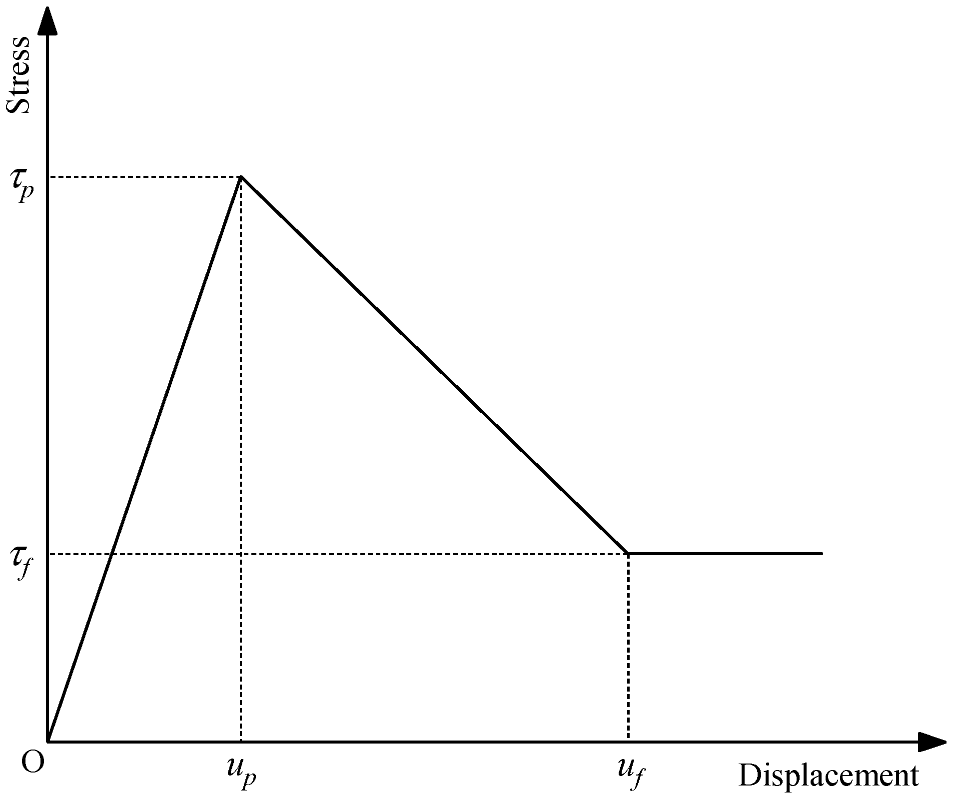
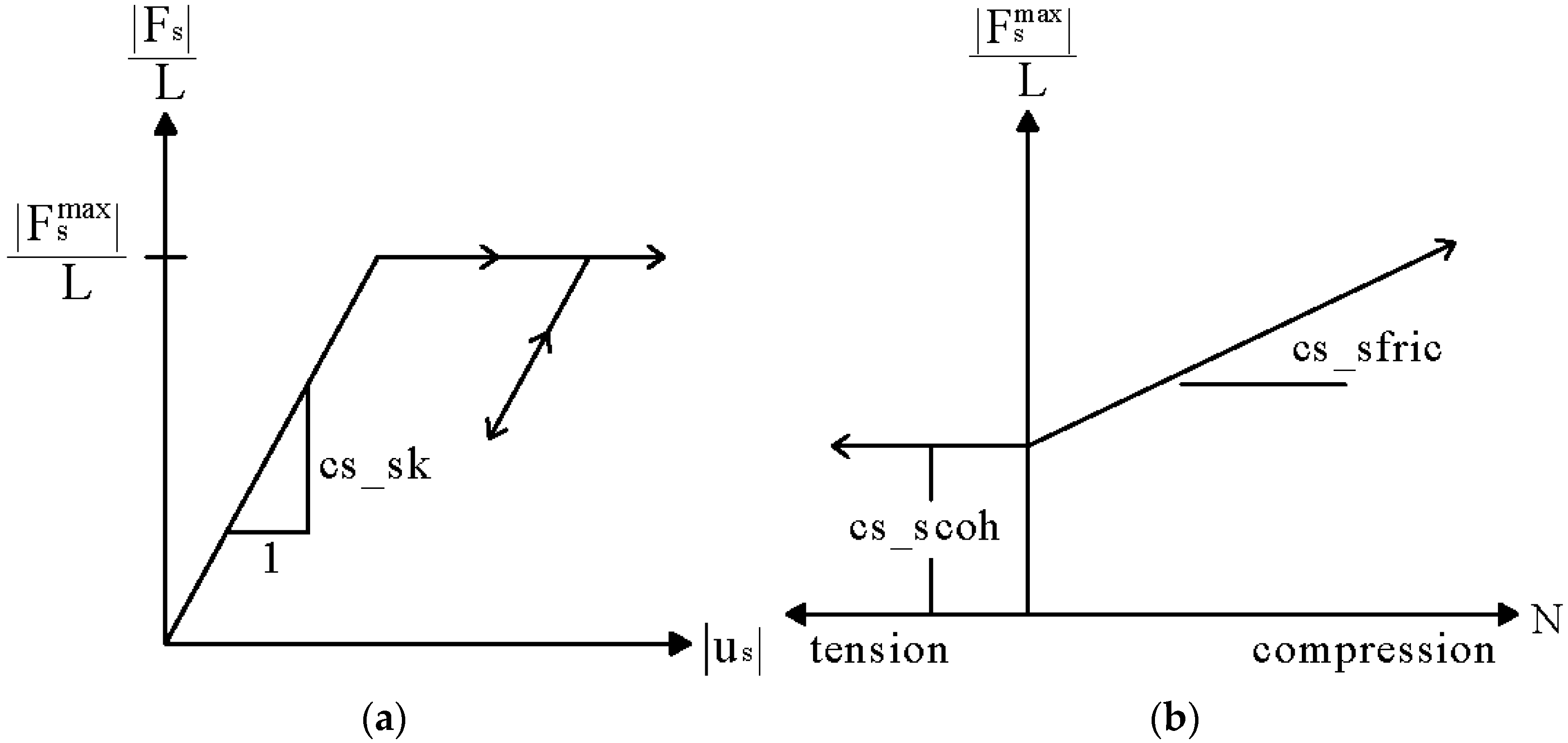
2.1. Realization of Mechanical Behavior of Anchorage Interface

FLAC3D is a commonly used numerical analysis software in mining engineering. In FLAC3D, the Cable and Pile structural elements can simulate bolts well. The Cable structural element uses a spring-slider to describe the mechanical behavior of the anchoring interface [49], where the spring assembly represents the bonding stiffness of the anchoring interface, and the slide assembly represents the bonding force of the anchoring interface, as shown in Figure 2. The Pile structural element is similar to the Cable structural element, and the parameters of the grout are replaced by the parameters of the coupling spring. The Pile structural element can describe the bond-slip relationship of the anchoring interface according to the user-defined FISH language, which can better realize the strain-softening behavior of the anchoring interface [50,51].
For the shear behavior of the anchoring interface, Figure 3 shows the mechanical behavior of the tangential coupling spring in the Pile structural element. The relationship between shear force and displacement of the anchoring interface can be expressed as follows:
F s L = c s _ s k u s
where F s is the shear force of the anchoring interface; L is the bonding length; c s _ s k is the shear stiffness of the anchoring interface; and u s is the displacement of the anchoring interface. Assuming that the shear strength of the anchoring interface meets the Mohr-Coulomb strength criterion, it can be expressed as follows:
F s m a x L = c s _ s c o h + N tan c s _ s f r i c
where F s m a x is the peak shear force of the anchoring interface; c s _ s c o h is the bonding force of the anchoring interface; c s _ s f r i c is the friction angle of the anchoring interface; and N is the effective normal stress of the anchoring interface.

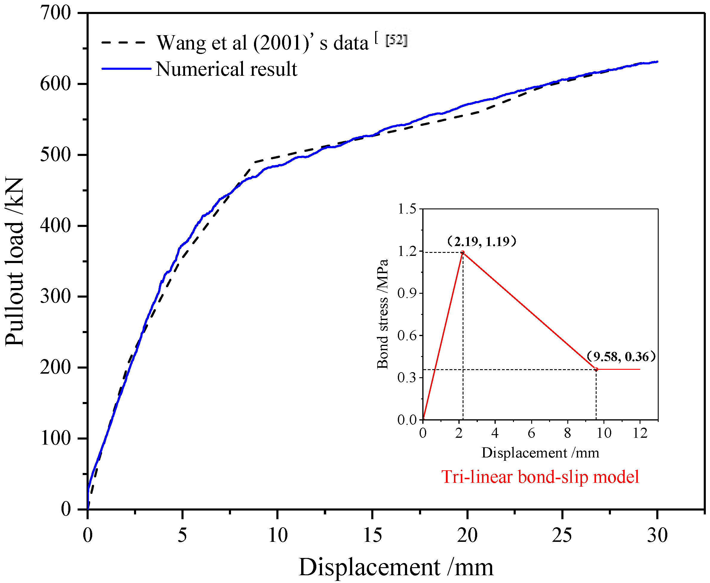
2.2. Model Verification

In order to verify the accuracy of the selected bolt model, the numerical results of the pullout bearing performance of the fully grouted bolts were compared with the test results of Wang et al. [52]. In Wang’s pullout test, the bolt length was 12 m, the bolt diameter was 32 mm and the borehole diameter was 150 mm. The parameters of the tri-linear bond-slip model of the anchoring interface were τ p = 1.19 MPa, τ f = 0.36 MPa, u p = 2.19 mm and u f = 9.58 mm. Figure 4 shows the comparison between the numerical results and the experimental results of the pullout load–displacement curve of fully grouted bolts. The results indicate that the Pile structural element can better realize the mechanical behavior of the bolt; the tri-linear bond-slip model can also better describe the bearing characteristics of the anchoring interface. The numerical results of the pullout load–displacement curve of fully grouted bolts are more consistent with the experimental results. Therefore, the method used in this study can better reflect the pullout bearing characteristics of fully grouted bolts.

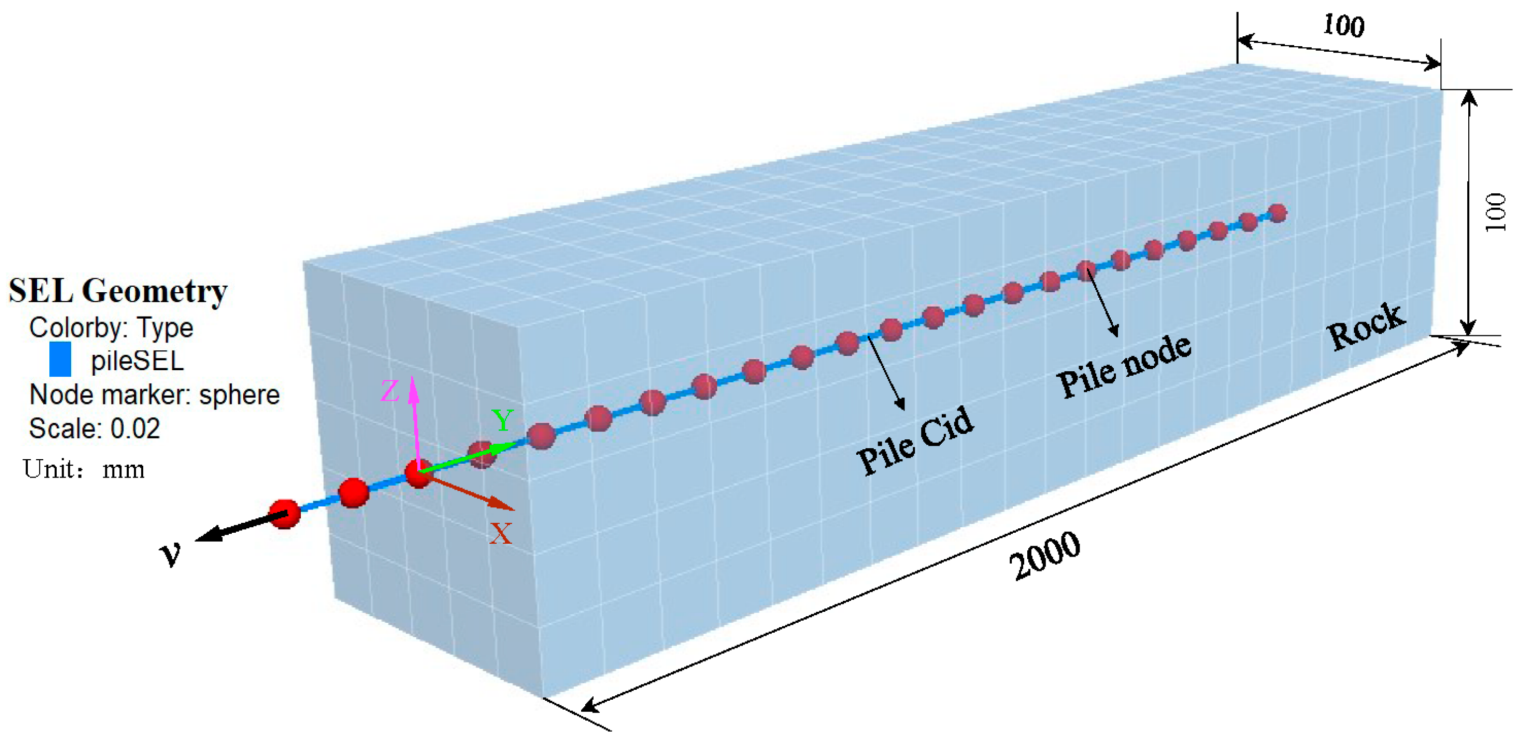
2.3. Pullout Calculation Model and Scheme Design

Figure 5 shows the numerical calculation model of fully grouted bolts established by FLAC3D. The numerical calculation model was a rectangular parallelepiped with a size of 2000 mm × 100 mm × 100 mm (length × width × height). The Pile structural element was used to simulate the bolt. The bolt diameter was 20 mm and the bolt bonding length was 2000 mm. The velocity in the y-direction of the model grid points on the y = 0 boundary was fixed, and other boundaries were free. The pullout velocity at the bolt loading end was set to 1 × 10⁻⁶ m/step.
Table 1 lists the values used in the numerical model. It should be noted that this study mainly focused on the shear mechanical behavior of the anchoring interface, so the following assumptions were made in the numerical modeling: (1) the tensile yield strength of the bolt was set to a very large value because the bolt was assumed to be elastic and will not yield; and (2) the isotropic elastic model was adopted to describe the mechanical behavior of the surrounding rock. In order to study the influence of specific parameters of the bond-slip model of the anchoring interface on the pullout bearing performance of fully grouted bolts, the variable controlling method was used in this study. The peak shear stress τ p was set as an invariant, and the displacement u p at the peak shear stress, the residual shear stress τ f and the displacement u f at the residual shear stress were set as variables. Table 2 lists the numerical experiment schemes of this study.

3. Parameters Analysis
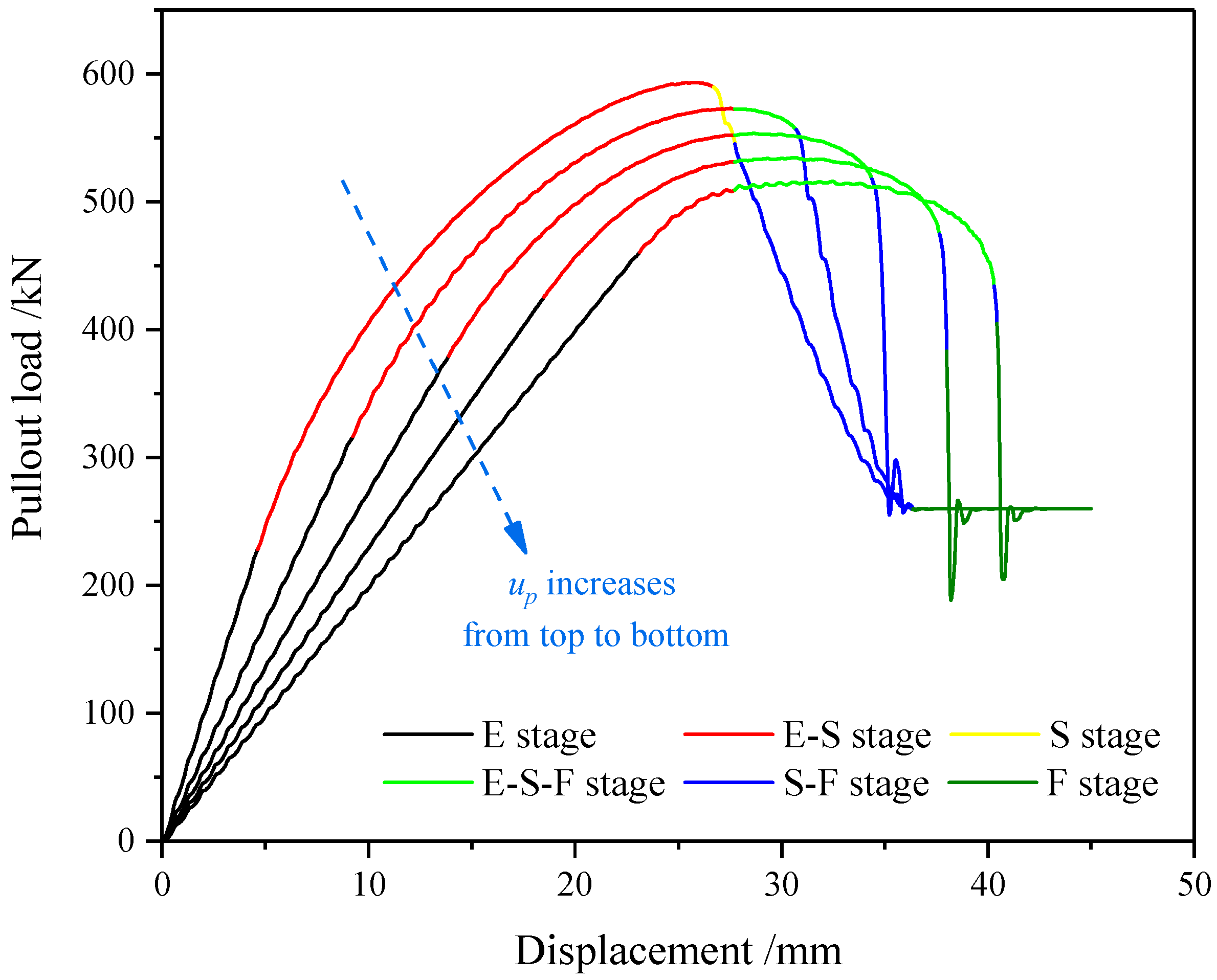
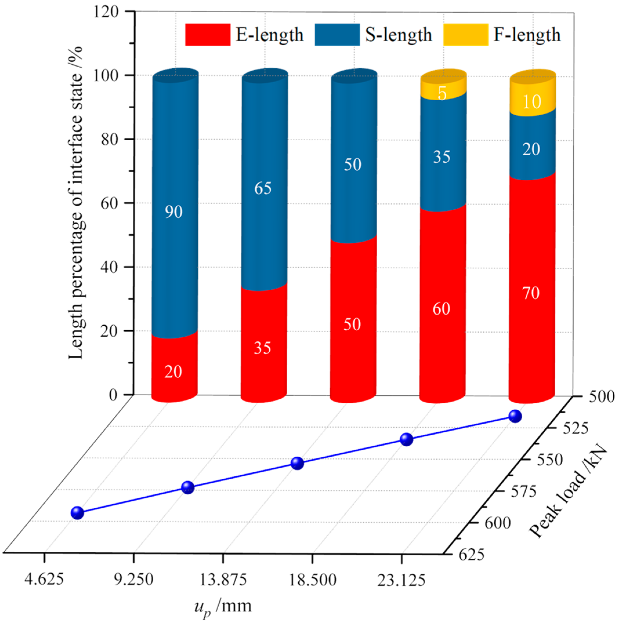
3.1. Displacement u p at Peak Bonding Stress

3.1.1. Bearing Properties Characteristic

Figure 6 shows the pullout load–displacement curve characteristics of fully grouted bolts when the displacement u p at the peak shear stress is different. It can be seen that the displacement u p at the peak shear stress will significantly affect the pullout load–displacement curve trend and pullout bearing process of the fully grouted bolts. With the increase in the displacement at the peak shear stress, the upward trend of the bearing curve before the peak pullout load gradually becomes flat, and the downward trend of the bearing curve after the peak pullout load gradually becomes steep. Obviously, the increase in displacement at the peak shear stress is not conducive to the timely response and timely support of the fully grouted anchoring system to the deformation of the roadway surrounding rock. Meanwhile, with the increase in the displacement at the peak shear stress, the pullout bearing process of fully grouted bolts gradually changes from one of the five stages (elastic stage, elastic-softening stage, softening stage, softening-friction stage and friction stage) to another of the five stages (elastic stage, elastic-softening stage, elastic-softening-friction stage, softening-friction stage and friction stage). It should be noted that the E stage, E-S stage, E-S-F stage, S-F stage and F stage in the figure represent the elastic stage, elastic-softening stage, elastic-softening-friction stage, softening-friction stage and friction stage, respectively.
Figure 7 shows the pullout properties of fully grouted bolts when the displacement u p at the peak shear stress is different. With the increase in the displacement at the peak shear stress, the peak load during the pullout process of fully grouted bolts gradually decreases, while the displacement at the peak load gradually increases. This indicates that the increase in displacement at the peak shear stress will weaken the bearing capacity of the fully grouted anchoring system, but will enhance the deformation capacity of the fully grouted anchoring system.
In order to better explain the influence of the displacement at the peak shear stress on the peak load of fully grouted bolts, the anchoring interface state characteristics corresponding to the peak load were analyzed, as shown in Figure 8. It should be noted that the E-length in the figure refers to the length of the elastic segment of the anchoring interface, the S-length refers to the length of the softening segment of the anchoring interface and the F-length refers to the length of the friction segment of the anchoring interface. With the increase in the displacement at the peak shear stress, the length of the elastic segment of the anchoring interface corresponding to the peak load gradually increases, the length of the softening segment gradually decreases and the length of the friction segment gradually increases. This is because the increase in displacement at the peak shear stress results in a decrease in the load growth rate in the elastic stage of the anchoring interface and an increase in the load reduction rate in the softening stage of the anchoring interface. During the pullout process of fully grouted bolts, the peak load occurrence stage gradually changes from the elastic-softening stage to the elastic-softening-friction stage. It can be seen that the increase in displacement at the peak shear stress will weaken the ability of the fully grouted anchoring system to resist external loads and reduce the bearing performance of fully grouted bolts.

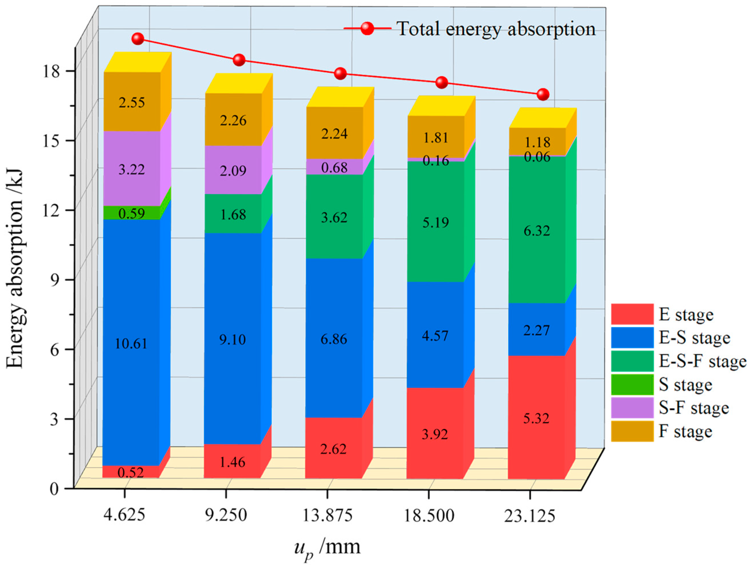
3.1.2. Energy Absorption Characteristic

Figure 9 shows the energy absorption characteristics of fully grouted bolts during the bearing process under different displacement u p at peak shear stress. Obviously, the change in displacement at the peak shear stress will affect the energy absorption characteristics of fully grouted bolts during the bearing process. With the increase in the displacement at the peak shear stress, the energy absorption in the elastic stage increases, the energy absorption in the elastic-softening stage decreases, the energy absorption in the elastic-softening-friction stage increases, the energy absorption in the softening-friction stage decreases, and the energy absorption in the friction stage also decreases. Meanwhile, with the increase in the displacement at the peak shear stress, the total energy absorption of fully grouted bolts during the bearing process decreases. This indicates that the increase in displacement at the peak shear stress will reduce the durability of the fully grouted anchoring system and is detrimental to the support effect of fully grouted bolts.

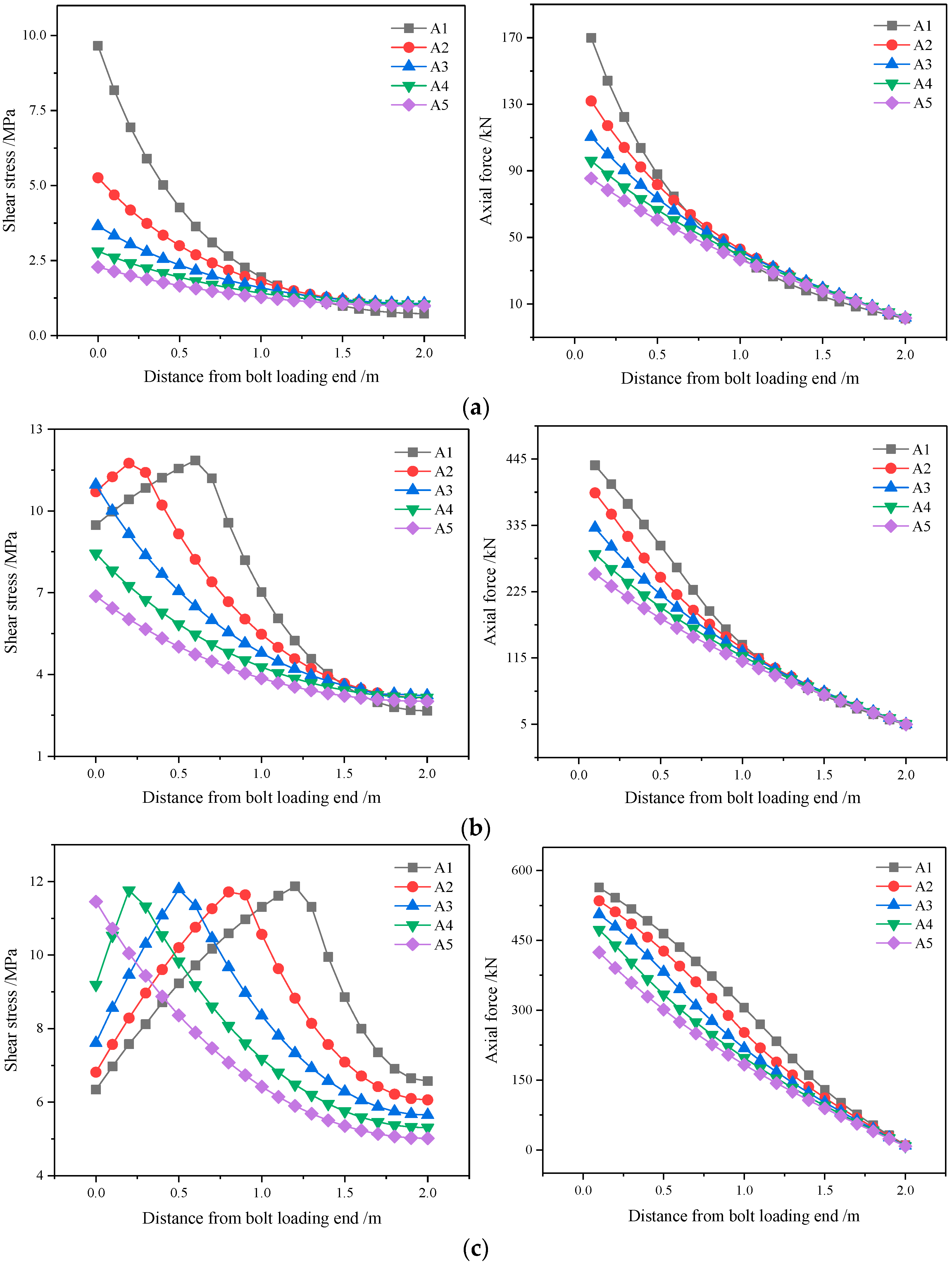
3.1.3. Stress Evolution Characteristic

Figure 10 shows the stress evolution characteristics of fully grouted bolts during the bearing process under different displacement u p at peak shear stress. It can be seen that the change in displacement at the peak shear stress will significantly affect the stress evolution characteristics of fully grouted bolts during the bearing process. When the pullout displacement is 5 mm, the shear stress and axial force during the bearing process of fully grouted bolts show a decreasing trend along the bolt length direction. With the increase in the displacement at the peak shear stress, the shear stress and axial force at the bolt loading end gradually decrease. When the pullout displacement is 15 mm, with the increase in the displacement at the peak shear stress, the shear stress gradually changes from a decreasing trend to first increasing and then decreasing during the bearing process of fully grouted bolts, and the axial force still shows a decreasing trend.
When the pullout displacement is 25 mm and with the increase in the displacement at the peak shear stress, the peak shear stress during the bearing process of fully grouted bolts gradually moves away from the bolt loading end; the shear stress shows two changing trends: decreasing trend and first increasing and then decreasing trend; the axial force shows a decreasing trend, but the change process of the axial force gradually changes from concave to convex. When the pullout displacement is 35 mm, the fully grouted bolt gradually loses the bearing performance. With the increase in the displacement at the peak shear stress, the shear stress shows two changing trends: unchanged-increasing trend and unchanged-increasing-decreasing trend; the axial force also gradually changes from a linear decreasing trend to a nonlinear decreasing trend. This indicates that the increase in displacement at the peak shear stress will reduce the response capabilities of fully grouted bolts to external loads and weaken the durability of the fully grouted anchoring system.

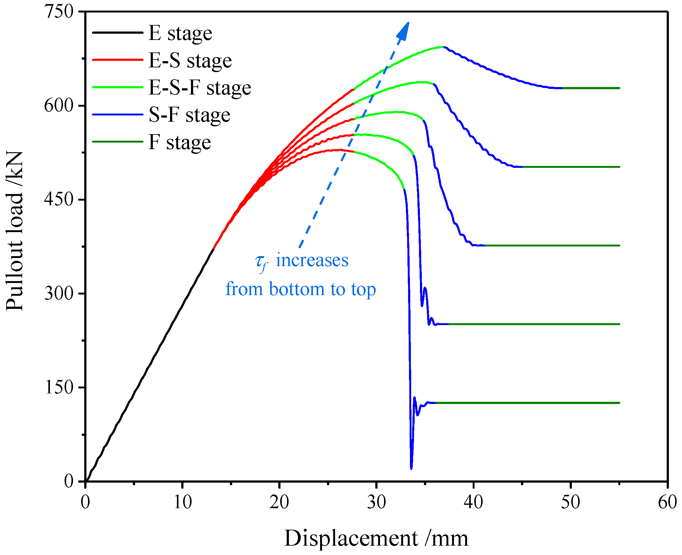
3.2. Residual Bonding Stress τ f

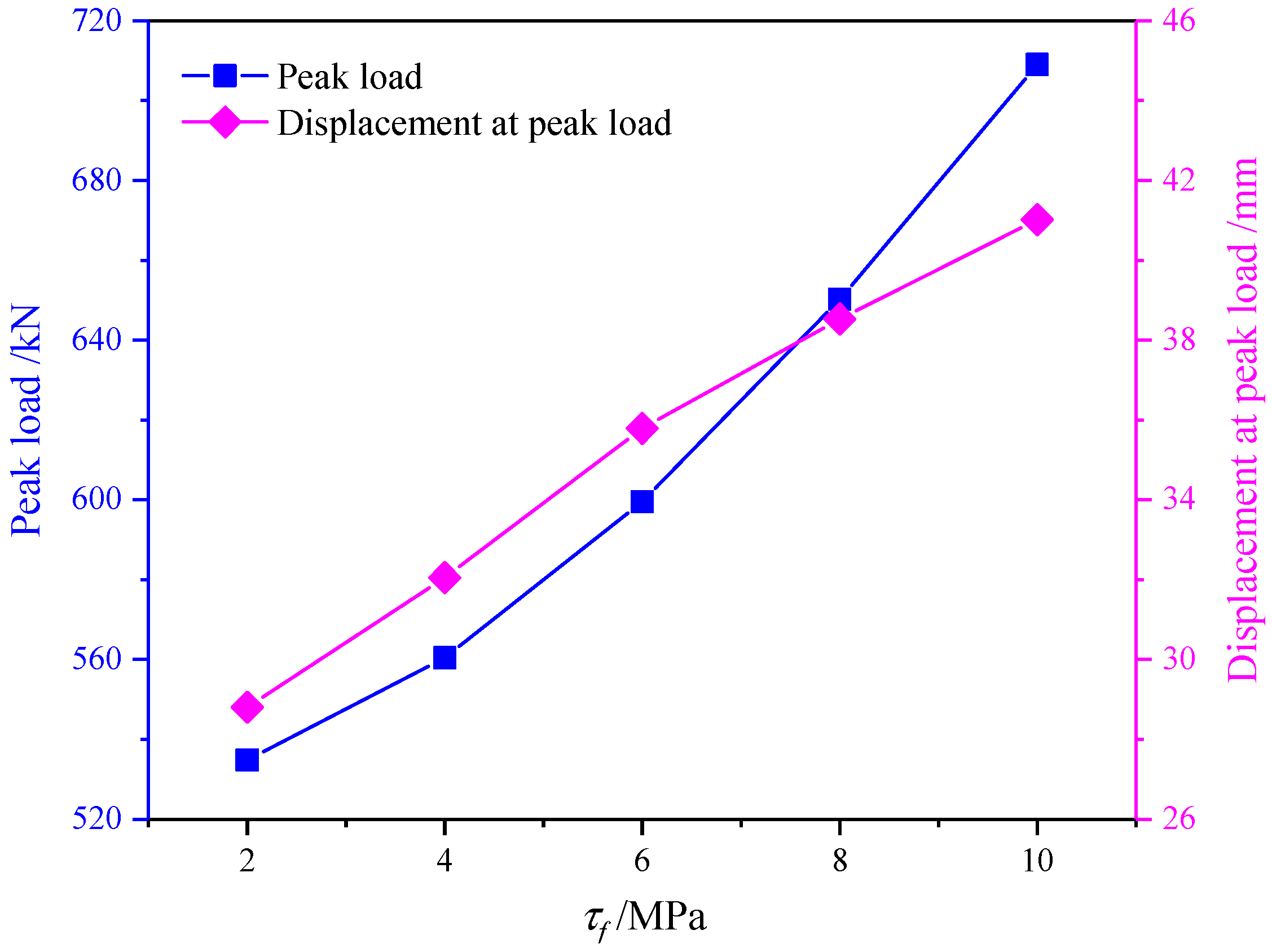
3.2.1. Bearing Properties Characteristic

Figure 11 shows the pullout load–displacement curve characteristic of fully grouted bolts under different residual shear stresses τ f . The bearing process of fully grouted bolts is divided into five stages: elastic stage (E stage), elastic-softening stage (E-S stage), elastic-softening-friction stage (E-S-F stage), softening-friction stage (S-F stage) and friction stage (F stage). With the increase in the residual shear stress, the growth rate of the pullout load before the peak load gradually increases, and the decrease rate of the pullout load after the peak load gradually decreases. Meanwhile, with the increase in the residual shear stress, the residual bearing capacity of fully grouted bolts also gradually increases.
Figure 12 shows the pullout properties of fully grouted bolts under different residual shear stresses τ f . With the increase in the residual shear stress, the peak load of fully grouted bolts during the pullout process gradually increases, and the displacement at the peak load also gradually increases. It can be seen that the increase in residual shear stress will improve the bearing performance of fully grouted bolts and strengthen the ability of the fully grouted anchoring system to resist failure.
In order to better explain the influence of the residual shear stress on the pullout bearing performance of fully grouted bolts, the anchoring interface state characteristics corresponding to the peak load were analyzed, as shown in Figure 13. With the increase in the residual shear stress, the length of the elastic segment of the anchoring interface corresponding to the peak load gradually decreases, and the length of the softening segment and the friction segment gradually increases. This is due to the increase in residual shear stress, leading to a decrease in the load reduction rate in the softening stage of the anchoring interface. The peak load occurrence stage of fully grouted bolts during the pullout process gradually changes from the elastic-softening stage to the elastic-softening-friction stage. It can be seen that the increase in residual shear stress can fully mobilize the bearing performance of fully grouted bolts, improve the ability of the fully grouted anchoring system to withstand external loads and enhance the durability of the fully grouted anchoring system.

3.2.2. Energy Absorption Characteristic

Figure 14 shows the energy absorption characteristics of fully grouted bolts during the bearing process under different residual shear stresses τ f . It can be seen that the change in residual shear stress will significantly affect the energy absorption characteristics of fully grouted bolts. With the increase in the residual shear stress, the energy absorption in the elastic stage remains basically unchanged, the energy absorption in the elastic-softening stage, the elastic-softening-friction stage and the softening-friction stage gradually increases, and the energy absorption in the friction stage increases first and then decrease. Meanwhile, with the increase in the residual shear stress, the total energy absorption of fully grouted bolts during the bearing process increases. This indicates that the increase in residual shear stress can improve the bearing performance of fully grouted bolts, strengthen the interaction between the bolt and the surrounding rock, and improve the support effect of the fully grouted anchoring system.

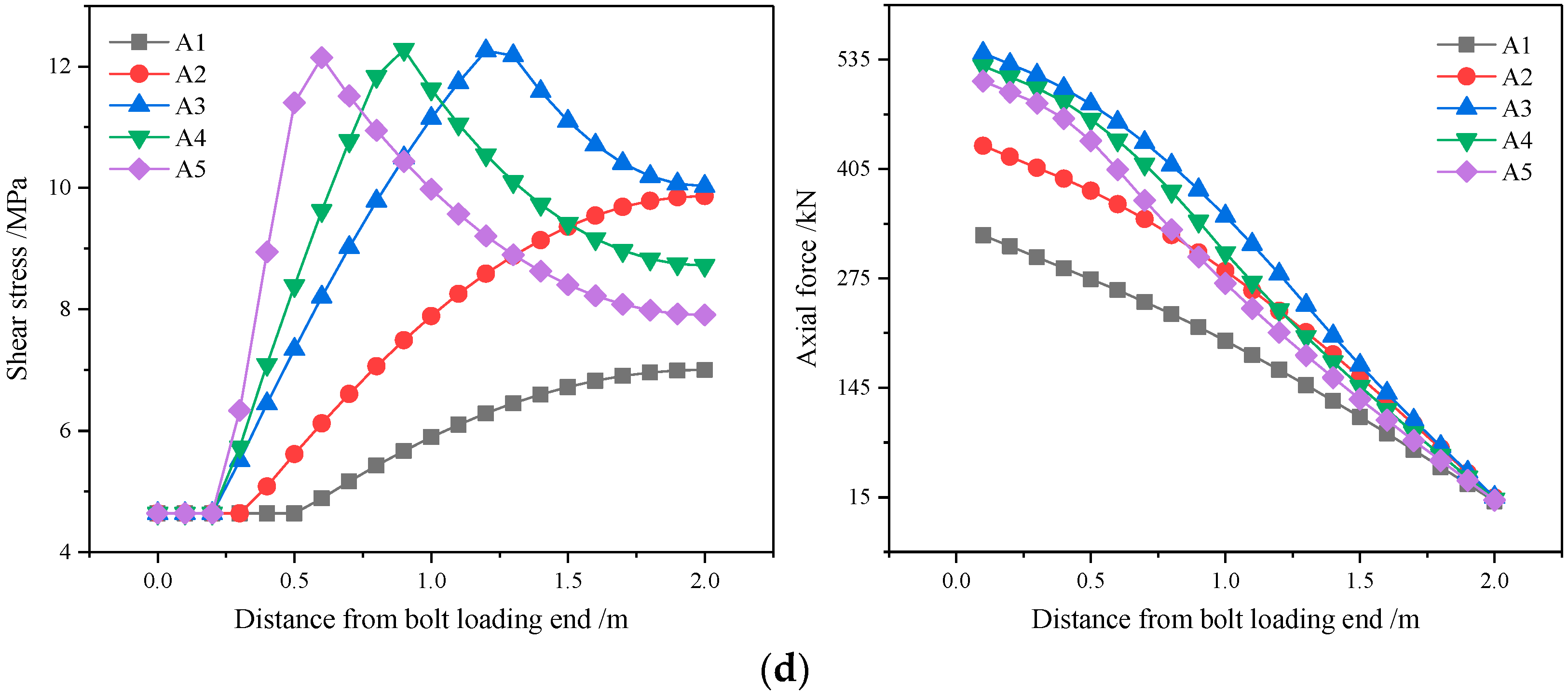
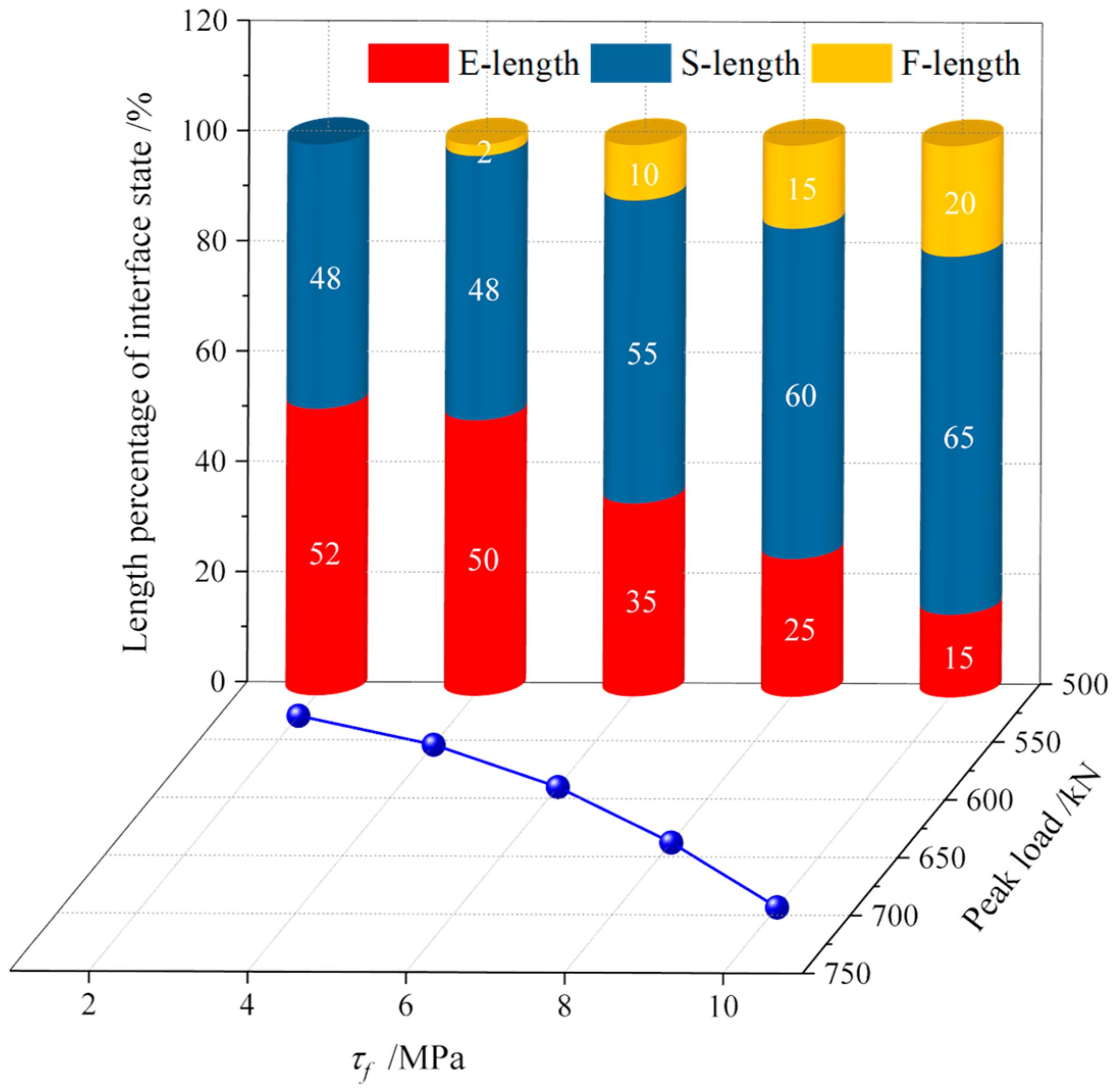
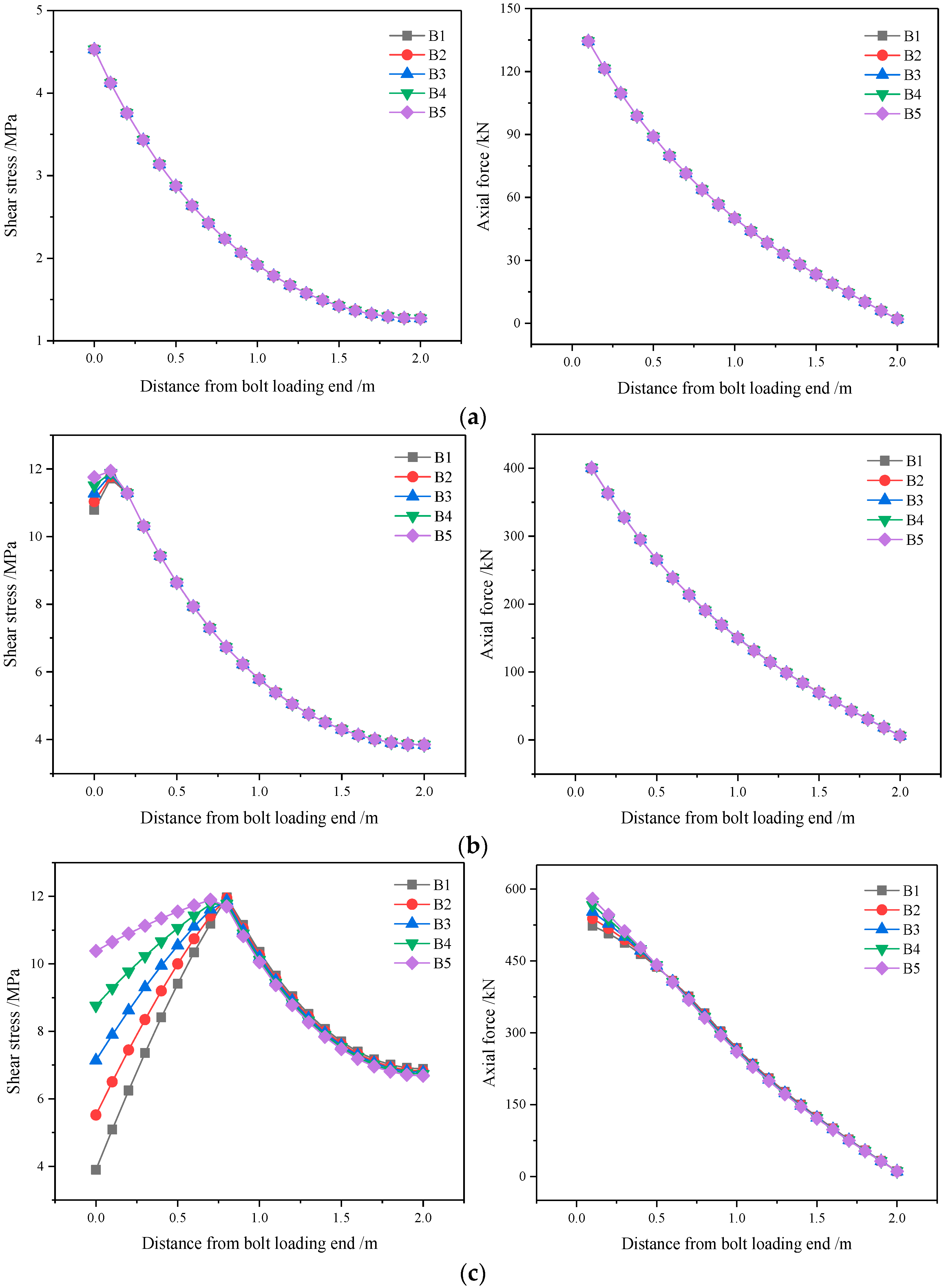
3.2.3. Stress Evolution Characteristic
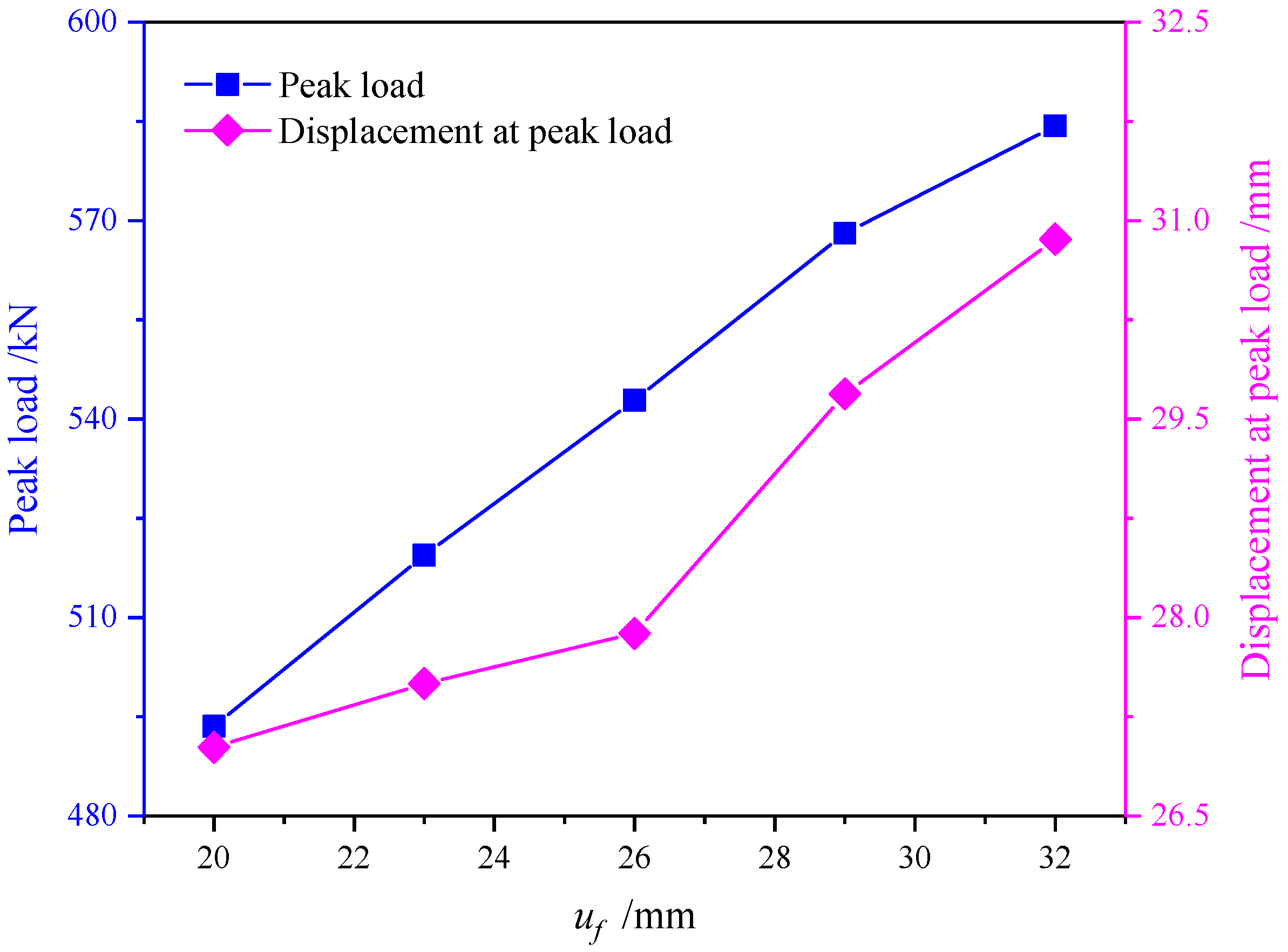
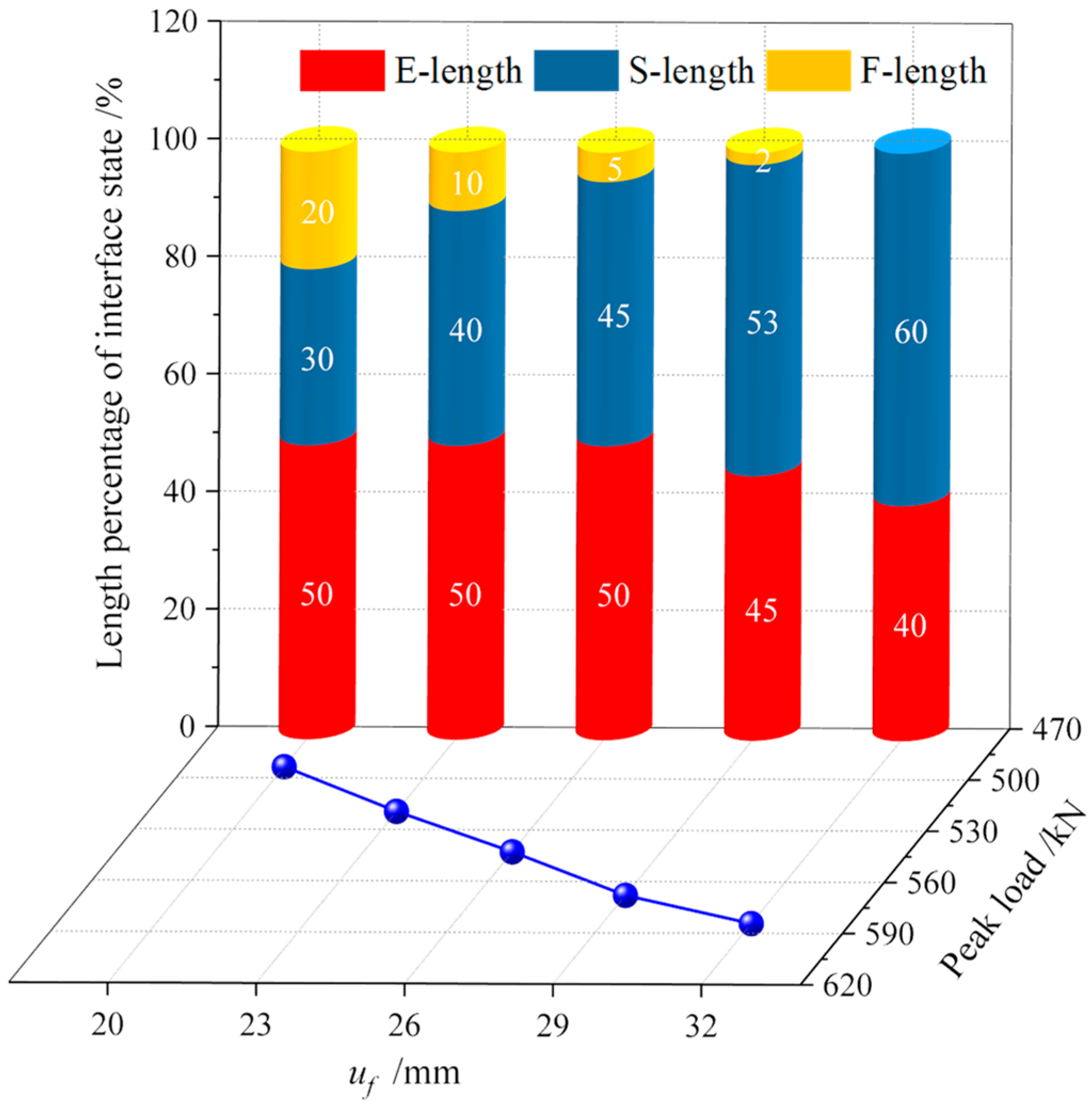
Figure 15 shows the stress evolution characteristics of fully grouted bolts during the bearing process under different residual shear stresses τ f . It can be seen that the residual shear stress τ f has a great influence on the stress evolution characteristics of fully grouted bolts during the bearing process. When the pullout displacement is 5 mm, the change in residual shear stress has little influence on the stress characteristics of fully grouted bolts, and the shear stress and axial force both show a nonlinear decreasing trend along the bolt length direction. When the pullout displacement is 15 mm, the anchoring interface at the bolt loading end begins to soften, the shear stress first increases and then decreases, and the axial force shows a nonlinear decreasing trend. With the increase in the residual shear stress, the reduction amplitude and rate of the shear stress near the bolt loading end gradually decreases.
When the pullout displacement is 25 mm, the influence of changes in residual shear stress on the stress evolution characteristics of fully grouted bolts during the bearing process becomes gradually more significant, the shear stress shows an increasing-decreasing trend and the axial force shows a decreasing trend. With the increase in the residual shear stress, the shear stress near the bolt loading end gradually increases, the softening behavior of the anchoring interface gradually weakens and the axial force near the bolt loading end gradually increases. When the pullout displacement is 35 mm, the fully grouted bolt gradually loses its bearing capacity. When the residual shear stress is small, the shear stress remains unchanged; with the increase in the residual shear stress, the shear stress gradually changes from an unchanged-increasing trend to an unchanged-increasing-decreasing trend, and the shear stress value near the bolt loading end also gradually increases. With the increase in the residual shear stress, the axial force gradually changes from a linear decreasing trend to a nonlinear decreasing trend, and the axial force value near the bolt loading end gradually increases. This indicates that the increase in residual shear stress can effectively improve the bearing capacity of fully grouted bolts and strengthen the ability of the fully grouted anchoring system to resist failure.

3.3. Displacement u f at Residual Bonding Stress

3.3.1. Bearing Properties Characteristic

Figure 16 shows the pullout load–displacement curves characteristic of fully grouted bolts when the displacement u f at the residual shear stress is different. It can be seen that the displacement u f at the residual shear stress has a great influence on the pullout bearing performance of fully grouted bolts. The bearing process of fully grouted bolts is divided into five stages: elastic stage (E stage), elastic-softening stage (E-S stage), elastic-softening-friction stage (E-S-F stage), softening-friction stage (S-F stage) and friction stage (F stage). With the increase in the displacement at the residual shear stress, the load increase rate before the peak pullout load gradually increases, and the load decrease rate after the peak pullout load gradually decreases.
Figure 17 shows the pullout properties of fully grouted bolts when the displacement u f at the residual shear stress is different. With the increase in the displacement at the residual shear stress, the peak load during the pullout process of fully grouted bolts gradually increases, and the displacement at the peak load also gradually increases. It can be seen that the increase in displacement at the residual shear stress will improve the bearing capacity and deformation capacity of the fully grouted anchoring system and enhance the ability of the fully grouted anchoring system to resist failure.
In order to better explain the influence of the displacement at the residual shear stress on the pullout bearing performance of fully grouted bolts, the anchoring interface state characteristics corresponding to the peak load were analyzed, as shown in Figure 18. With the increase in the displacement at the residual shear stress, the length of the elastic segment and the friction segment of the anchoring interface corresponding to the peak load gradually decrease, and the length of the softening segment gradually increases. This is due to the increase in displacement at the residual shear stress, leading to a decrease in the load reduction rate in the softening stage of the anchoring interface. The peak load occurrence stage of fully grouted bolts during the pullout process gradually changes from the elastic-softening-friction stage to the elastic-softening stage. It can be seen that the increase in displacement at the residual shear stress can better mobilize the softening performance of the anchoring interface and help the fully grouted anchoring system to better exert the bearing capacity. Therefore, the peak load of fully grouted bolts during the pullout process gradually increases.

3.3.2. Energy Absorption Characteristic

Figure 19 shows the energy absorption characteristics of fully grouted bolts during the pullout process when the displacement u f at the residual shear stress is different. During the bearing process of fully grouted bolts and with the increase in the displacement at the residual shear stress, the energy absorption in the elastic stage does not change, the energy absorption in the elastic-softening stage gradually increases, the energy absorption in the elastic-softening-friction stage gradually decreases, the energy absorption in the softening-friction stage gradually increases and the energy absorption in the friction stage gradually decreases. Meanwhile, with the increase in the displacement at the residual shear stress, the total energy absorption of fully grouted bolts during the bearing process gradually increases. It indicates that the increase in displacement at the residual shear stress is beneficial to the bearing performance of the fully grouted anchoring system and can better realize the deformation and damage control of the roadway surrounding rock.

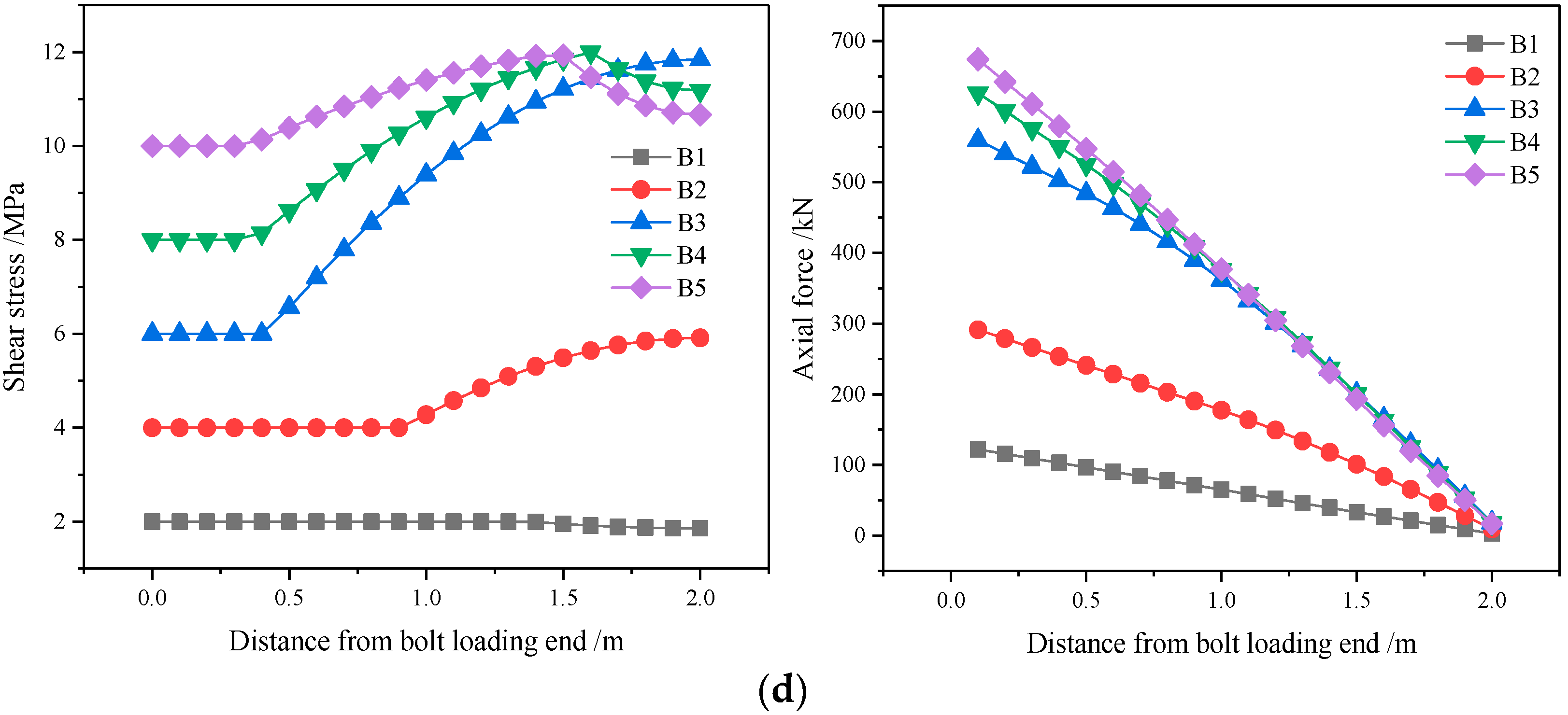
3.3.3. Stress Evolution Characteristic

Figure 20 shows the stress characteristics of fully grouted bolts during the pullout process when the displacement u f at the residual shear stress is different. It can be seen that the displacement u f at the residual shear stress has a great influence on the stress characteristics of fully grouted bolts during the pullout process. When the pullout displacement is 5 mm, the displacement at the residual shear stress has no effect on the stress characteristics of fully grouted bolts during the bearing process, and the shear stress and axial force of fully grouted bolts show a nonlinear decreasing trend along the bolt length direction. When the pullout displacement is 15 mm, the anchoring interface of fully grouted bolts begins to soften, and the shear stress shows an increasing-decreasing trend. With the increase in the displacement at the residual shear stress, the reduction amplitude and rate of shear stress near the bolt loading end gradually decrease. The axial force still shows a decreasing trend and is not affected by the changes in displacement at the residual shear stress.
When the pullout displacement is 25 mm, the change in displacement at the residual shear stress has a more significant influence on the stress characteristics of fully grouted bolts. With the increase in the displacement at the residual shear stress, the shear stress gradually changes from the unchanged-increasing-decreasing trend to the increasing-decreasing trend, and the maximum value of the axial force near the bolt loading end gradually increases. When the pullout displacement is 35 mm, the fully grouted bolts corresponding to the smaller displacement at the residual shear stress almost completely lose the bearing capacity, the shear stress does not change and is constant and the axial force decreases linearly. With the increase in the displacement at the residual shear stress, the shear stress gradually changes from unchanged to unchanged-increasing trend, the axial force gradually changes from linear decrease to nonlinear decrease and the maximum value of the axial force gradually increases. This indicates that the increase in displacement at the residual shear stress can slow down the progressive failure process of fully grouted bolts, improve the ability of the fully grouted anchoring system to resist failure and enhance the durability of the fully grouted anchoring system.

4. Discussion

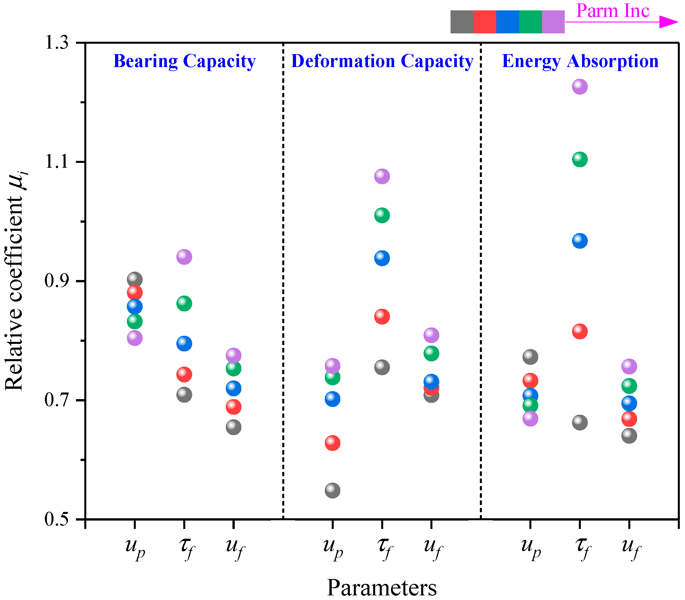
4.1. Effects on Bearing Characteristics

Figure 21 shows the effects of the shear strength parameters of the anchoring interface on the pullout bearing performance of fully grouted bolts. For a better description, the relative coefficient μ i of the bearing performance of fully grouted bolts is defined, and the specific expression is as follows:
μ i = B P n / B P t
where B P n refers to the bearing properties of fully grouted bolts when the shear strength parameters of the anchoring interface are fully considered; B P t refers to the bearing properties of fully grouted bolts when only the peak shear stress of the anchoring interface is considered. For the bearing capacity of fully grouted bolts, the relative coefficient is 0.80~0.90 when the displacement u p at the peak shear stress changes, the relative coefficient is 0.71~0.95 when the residual shear stress τ f changes and the relative coefficient is 0.65~0.77 when the displacement u f at the residual shear stress changes. It can be seen that the displacement at the residual shear stress has the greatest effect on the bearing capacity of fully grouted bolts, followed by the residual shear stress, and the displacement at the peak shear stress has the smallest effect.
For the deformation capacity of fully grouted bolts, the relative coefficient is 0.55~0.75 when the displacement u p at the peak shear stress changes, the relative coefficient is 0.76~1.08 when the residual shear stress τ f changes and the relative coefficient is 0.71~0.81 when the displacement u f at the residual shear stress changes. It can be seen that the displacement at the peak shear stress has the greatest effect on the deformation capacity of fully grouted bolts, followed by the displacement at the residual shear stress, and the residual shear stress has the smallest effect. For the energy absorption of fully grouted bolts, the relative coefficient is 0.67~0.77 when the displacement u p at the peak shear stress changes, the relative coefficient is 0.66~1.23 when the residual shear stress τ f changes and the relative coefficient is 0.64~0.76 when the displacement u f at the residual shear stress changes. It can be seen that the displacement at the residual shear stress has the greatest effect on the energy absorption of fully grouted bolts, followed by the residual shear stress, and the displacement at the peak shear stress has the smallest effect.

4.2. Thoughts on the Design of Bolt Support

In order to better realize roadway safety and ensure the sustainable development of coal mines, some thoughts for coal mine roadway bolt support are as follows, based on the above research:
(1)
The shear strength parameters of the anchoring interface have a great influence on the design of bolt support. It is inappropriate to only use the peak shear stress of the anchoring interface for bolt support design, which often overestimates the bearing performance of the anchoring system and brings hidden dangers to roadway safety. Therefore, the shear strength parameters of the anchoring interface must be fully considered when designing bolt support.
(2)
Improving the post-peak characteristics of the bond-slip model of the anchoring interface can significantly increase the bearing performance of the anchoring system. Therefore, when designing bolt supports, materials such as gravel or steel fibers can be added to the agent grout [53,54,55], or the roughness of the anchoring interface can be increased to strengthen the shear behavior of the anchoring interface and improve the shear strength parameters of the anchoring interface, thereby enhancing the durability of the anchoring system.
(3)
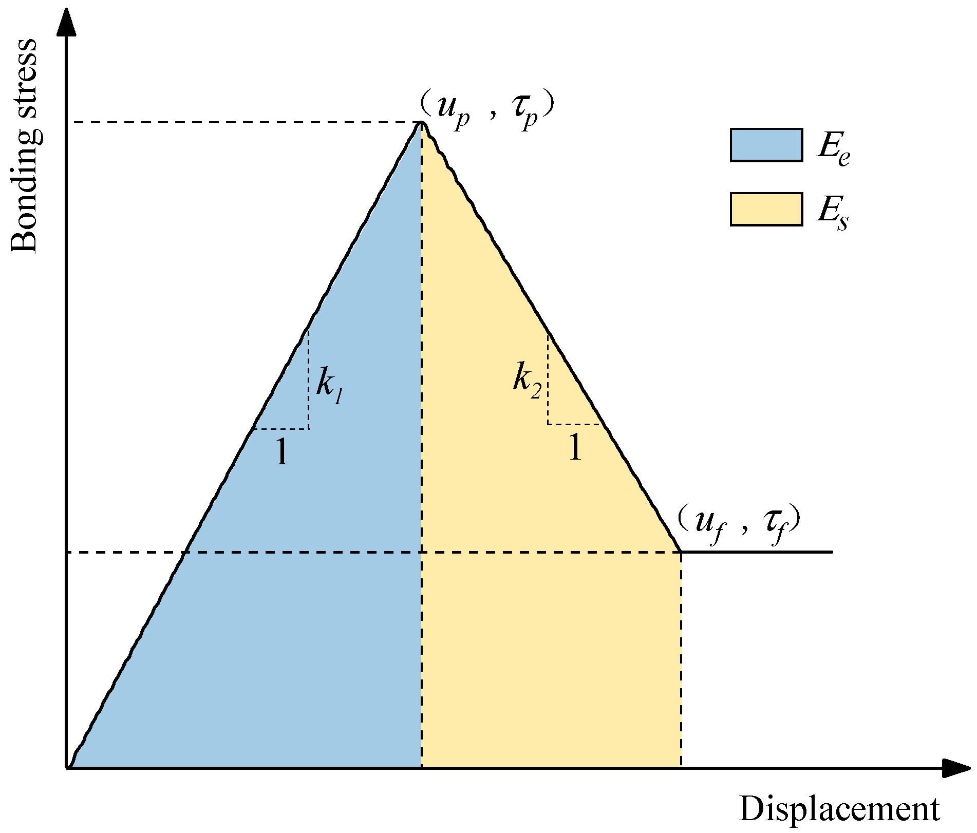
The bearing process of the anchoring system is the process of energy dissipation at the anchoring interface. Combined with the bond-slip model of the anchoring interface, the energy dissipation ratio of the anchoring interface is defined in this study. The energy dissipation ratio ξ of the anchoring interface is the ratio of softening energy E s to elastic energy E e during the bearing process of the anchoring interface ( ξ = E s E e ), as shown in Figure 22.
In this study, when the displacement u p at the peak shear stress increases, the energy dissipation ratio gradually decreases, and the bearing capacity of fully grouted bolts also gradually decreases; while when the residual shear stress τ f and the displacement u f at the residual shear stress increase, the energy dissipation ratio gradually increases, and the bearing capacity of fully grouted bolts also gradually increases. It can be seen that increasing the energy dissipation ratio of the anchoring interface can improve the bearing performance of the anchoring system. Therefore, during the design process of bolt support, increasing the softening energy or reducing the elastic energy during the bearing process of the anchoring interface will help the anchoring system better withstand external loads. This also explains that strengthening the post-peak bearing characteristics of the anchoring interface is conducive to the fully grouted anchoring system to better exert the bearing performance.

5. Conclusions

This paper studies the effects of the shear strength parameters of the anchoring interface on the pullout bearing performance of fully grouted bolts. The pullout model of fully grouted bolts was established by FLAC3D. The commonly used tri-linear bond-slip model of the anchoring interface was selected to analyze the effects of the displacement at the peak shear stress, the residual shear stress and the displacement at the residual shear stress on the bearing properties, energy absorption characteristics and stress evolution laws of fully grouted bolts. The main conclusions are as follows:
(1)
The displacement at the peak shear stress will significantly affect the pullout bearing process of fully grouted bolts. With the increase in the displacement at the peak shear stress, the bearing capacity of fully grouted bolts gradually decreases, the energy absorption also decreases and the response rate of the fully grouted anchoring system to external loads weakens. However, the ability of the fully grouted anchoring system to resist failure increases with the increase in the displacement at the peak shear stress, and the durability of the fully grouted anchoring system increases.
(2)
The residual shear stress has a great influence on the pullout bearing performance of fully grouted bolts. With the increase in the residual shear stress, the bearing capacity and deformation capacity of fully grouted bolts increase, and the energy absorption also increases. Meanwhile, the increase in residual shear stress gives fully grouted bolts higher residual bearing capacity, which helps the fully grouted anchoring system to better withstand external loads.
(3)
With the increase in the displacement at the residual shear stress, the bearing capacity and deformation capacity of fully grouted bolts show an increasing trend, and the energy absorption of fully grouted bolts also increases. The increase in displacement at the residual shear stress enhances the durability of the fully grouted anchoring system, which is beneficial to fully grouted bolts to better exert the support performance.
(4)
The shear strength parameters of the anchoring interface will significantly affect the pullout bearing performance of fully grouted bolts. Therefore, when designing bolt support, in addition to considering the peak shear stress of the anchoring interface, it is also necessary to fully consider the post-peak shear strength parameters of the anchoring interface to avoid overestimating or underestimating the bearing capacity of the anchoring system. Meanwhile, measures can be taken to strengthen the post-peak bearing characteristics of the anchoring interface, which is beneficial to the bearing performance of the anchoring system.
The research results may provide guidance for the design and performance improvements of fully grouted bolts in coal mine roadways.

Author Contributions

Conceptualization, Y.D.; methodology, Y.D.; software, Y.D.; validation, G.F. and Y.Z.; formal analysis, G.F. and Y.Z.; investigation, G.F. and Y.Z.; resources, Y.D. and L.H.; data curation, Y.D. and L.H.; writing—original draft preparation, Y.D.; writing—review and editing, G.F., Y.Z. and X.Z.; visualization, Y.D.; supervision, G.F., Y.Z. and X.Z.; project administration, Y.D. and G.F.; funding acquisition, Y.D. All authors have read and agreed to the published version of the manuscript.

Funding

This research was funded by the Distinguished Youth Funds of the National Natural Science Foundation of China, grant number 51925402, the New Cornerstone Science Foundation through the XPLORER PRIZE, the Fundamental Research Program of Shanxi Province, grant number 20210302123094, and the Research Project Supported by Shanxi Scholarship Council of China, grant number 2023-041.

Data Availability Statement

The materials and the data that support the findings of this study are available from the corresponding author.

Acknowledgments

The authors sincerely acknowledge the former researchers for their excellent works, which greatly assisted this academic study. The authors are very grateful to the editors and reviewers for their kind and invaluable comments.

Conflicts of Interest

Author Yunlou Du was employed by the company Shandong Taifeng Holding Group Co., Ltd. The remaining authors declare that the research was conducted in the absence of any commercial or financial relationships that could be construed as a potential conflict of interest.

References

  1. Qian, M.; Miao, X.; Xu, J. Green mining of coal resources harmonizing with environment. J. China Coal Soc. 2007, 32, 1–7. (In Chinese) [Google Scholar] [CrossRef]
  2. Kang, H. Sixty years development and prospects of rock bolting technology for underground coal mine roadways in China. J. Univ. Min. Technol. 2016, 45, 1071–1081. (In Chinese) [Google Scholar] [CrossRef]
  3. Du, Y.; Feng, G.; Kang, H.; Zhang, X.; Zhang, Y.; Shi, X.; Wen, X. Investigation on the mechanical behavior and failure characteristics of fully grouted bolts under tension. Energy Sources Part A Recovery Util. Environ. Eff. 2020, 10, 1–15. [Google Scholar] [CrossRef]
  4. Kang, H.; Cui, Q.; Hu, B.; Wu, Z. Analysis on anchorage performances and affecting factors of resin bolts. J. China Coal Soc. 2014, 39, 1–10. (In Chinese) [Google Scholar] [CrossRef]
  5. Windsor, C. Rock reinforcement systems. Int. J. Rock Mech. Min. Sci. 1997, 34, 919–951. [Google Scholar] [CrossRef]
  6. Cao, C.; Nemcik, J.; Aziz, N.; Ren, T. Analytical study of steel bolt profile and its influence on bolt load transfer. Int. J. Rock Mech. Min. Sci. 2013, 60, 188–195. [Google Scholar] [CrossRef]
  7. Benmokrane, B.; Chennouf, A.; Mitri, H. Laboratory evaluation of cement-based grouts and grouted rock anchors. Int. J. Rock Mech. Min. Sci. Geomech. Abstr. 1995, 32, 633–642. [Google Scholar] [CrossRef]
  8. Wu, Z.; Yang, S.; Hu, X.; Zheng, J. Analytical method for pullout of anchor from anchor-mortar-concrete anchorage system due to shear failure of mortar. J. Eng. Mech. 2007, 133, 1352–1369. [Google Scholar] [CrossRef]
  9. Yang, S.; Wu, Z.; Hu, X.; Zheng, J. Theoretical analysis on pullout of anchor from anchor-mortar-concrete anchorage system. Eng. Fract. Mech. 2008, 75, 961–985. [Google Scholar] [CrossRef]
  10. Wu, Z.; Yang, S.; Wu, Y.; Hu, X. Analytical method for failure of anchor-grout-concrete anchorage due to concrete cone failure and interfacial debonding. J. Struct. Eng. 2009, 135, 356–365. [Google Scholar] [CrossRef]
  11. Wu, Z.; Yang, S.; Zheng, J.; Hu, X. Analytical solution for the pull-out response of FRP rods embedded in steel tubes filled with cement grout. Mater. Struct. 2010, 43, 597–609. [Google Scholar] [CrossRef]
  12. Ren, F.; Yang, Z.; Chen, J.; Chen, W. An analytical analysis of the full-range behaviour of grouted rockbolts based on a tri-linear bond-slip model. Constr. Build. Mater. 2010, 24, 361–370. [Google Scholar] [CrossRef]
  13. Martín, L.; Tijani, M.; Hadj-hassen, F. A new analytical solution to the mechanical behaviour of fully grouted rockbolts subjected to pull-out tests. Constr. Build. Mater. 2011, 25, 749–755. [Google Scholar] [CrossRef]
  14. Guo, R.; Chen, W.; Duan, J.; Yan, Z. Pullout mechanical analysis of soil anchor based on softening behavior of interface. J. Cent. South Univ. (Sci. Technol.) 2012, 43, 4003–4009. (In Chinese) [Google Scholar]
  15. Luo, Y.; Shi, S.; Yan, Z. Shear interaction of the anchorage body and rock and soil interface under the action of uplift load. J. China Coal Soc. 2015, 40, 58–64. (In Chinese) [Google Scholar] [CrossRef]
  16. Cao, C.; Nemcik, J.; Ren, T.; Aziz, N. A study of rock bolting failure modes. Int. J. Min. Sci. Technol. 2013, 23, 79–88. [Google Scholar] [CrossRef]
  17. Chen, J.; Saydam, S.; Hagan, P. An analytical model of the load transfer behavior of fully grouted cable bolts. Constr. Build. Mater. 2015, 101, 1006–1015. [Google Scholar] [CrossRef]
  18. Lu, W.; Zhao, D.; Mao, X.; Ai, Y. Experimental study on bond-slip behavior of bamboo bolt-modified slurry interface under pull-out load. Adv. Civ. Eng. 2018, 2018, 1–23. [Google Scholar] [CrossRef]
  19. Lu, W.; Zhao, D.; Li, D.; Mao, X. Study on the force transfer process of the anchorage interface of bamboo bolt in the rammed earth sites. Chin. J. Theor. Appl. Mech. 2019, 51, 524–539. (In Chinese) [Google Scholar] [CrossRef]
  20. Wang, Y.; Wu, Z.; Zheng, J.; Zhou, X. Three-dimensional analytical model for the pull-out response of anchor-mortar-concrete anchorage system based on interfacial bond failure. Eng. Struct. 2019, 180, 234–248. [Google Scholar] [CrossRef]
  21. Wang, Y.; Wu, Z.; Zheng, J.; Zhou, X. 3D analytical investigation on the overall pullout behavior of grouted anchorages in presence of shear failure of grout. Eng. Fail. Anal. 2020, 109, 104249. [Google Scholar] [CrossRef]
  22. Zhu, C.; Chang, X.; Men, Y.; Luo, X. Modeling of grout crack of rockbolt grouted system. Int. J. Min. Sci. Technol. 2015, 25, 73–77. [Google Scholar] [CrossRef]
  23. Chang, X.; Wang, G.; Liang, Z.; Yang, J.; Tang, C. Study on grout cracking and interface debonding of rockbolt grouted system. Constr. Build. Mater. 2017, 135, 665–673. [Google Scholar] [CrossRef]
  24. Ma, S.; Zhao, Z.; Nie, W.; Gui, Y. A numerical model of fully grouted bolts considering the tri-linear shear bond-slip model. Tunn. Undergr. Space Technol. 2016, 54, 73–80. [Google Scholar] [CrossRef]
  25. You, C.; Zhan, Y.; Liu, Q.; Sun, L.; Wang, K. Shear lag-debonding model for anchorage section of prestressed anchor cable. Chin. J. Rock Mech. Eng. 2013, 32, 800–806. (In Chinese) [Google Scholar] [CrossRef]
  26. Cai, Y.; Esaki, T.; Jiang, Y. A rock bolt and rock mass interaction model. Int. J. Rock Mech. Min. Sci. 2004, 41, 1055–1067. [Google Scholar] [CrossRef]
  27. He, S.; Zhang, X.; Wang, C. Study on mechanism of prestressed anchoring cable based on modified shear lag model. Chin. J. Rock Mech. Eng. 2004, 15, 2562–2567. (In Chinese) [Google Scholar] [CrossRef]
  28. Xu, H.; Wang, W.; Jiang, M.; Tong, Q. Theoretical analysis of pullout deformation and stiffness of grouted rockbolts. Chin. J. Geotech. Eng. 2011, 33, 1511–1516. (In Chinese) [Google Scholar]
  29. Zhao, Y.; Yang, M. Pull-out behavior of an imperfectly bonded anchor system. Int. J. Rock Mech. Min. Sci. 2011, 48, 469–475. [Google Scholar] [CrossRef]
  30. Duan, J.; Yan, Z.; Guo, R.; Liu, Z.; Ren, Z. Failure analysis of soil anchors induced by loose interface under pullout load. Chin. J. Geotech. Eng. 2012, 34, 936–941. (In Chinese) [Google Scholar]
  31. Zhang, J.; Tang, B. Hyperbolic function model to analyze load transfer mechanism on bolts. Chin. J. Geotech. Eng. 2002, 24, 188–192. (In Chinese) [Google Scholar] [CrossRef]
  32. Zhou, Y.; Wu, Y.; Yun, Y. Analytical modeling of the bond-slip relationship at FRP-concrete interfaces for adhesively-bonded joints. Compos. Part B Eng. 2010, 41, 423–433. [Google Scholar] [CrossRef]
  33. Ma, S.; Nemcik, J.; Aziz, N. An analytical model of fully grouted rock bolts subjected to tensile load. Constr. Build. Mater. 2013, 49, 519–526. [Google Scholar] [CrossRef]
  34. Ma, S.; Nemcik, J.; Aziz, N.; Zhang, Z. Numerical modeling of fully grouted rockbolts reaching free-end slip. Int. J. Geomech. 2016, 16, 04015020. [Google Scholar] [CrossRef]
  35. Nemcik, J.; Ma, S.; Aziz, N.; Ren, T.; Geng, X. Numerical modelling of failure propagation in fully grouted rock bolts subjected to tensile load. Int. J. Rock Mech. Min. Sci. 2014, 71, 293–300. [Google Scholar] [CrossRef]
  36. Li, N.; Ma, Z.; Gong, P.; Qi, F.; Wang, T.; Cheng, S. Simulation research on the load transfer mechanism of anchoring system in soft and hard composite rock strata under tensile loading conditions. Adv. Mater. Sci. Eng. 2020, 2020, 9097426. [Google Scholar] [CrossRef]
  37. Huang, M.; Zhou, Z.; Ou, J. Nonlinear analysis on load transfer mechanism of wholly grouted anchor rod along anchoring section. Chin. J. Rock Mech. Eng. 2014, 33, 3992–3997. (In Chinese) [Google Scholar] [CrossRef]
  38. Huang, M.; Zhou, Z.; Ou, J. Nonlinear full-range analysis of load transfer in fixed segment of tensile anchors. Chin. J. Rock Mech. Eng. 2014, 33, 2190–2199. (In Chinese) [Google Scholar] [CrossRef]
  39. Huang, M.; Li, J.; Zhao, M.; Chen, C. Nonlinear analysis on load transfer mechanism of bolts in layered grouns. China J. Highw. Transp. 2019, 32, 12–20+56. (In Chinese) [Google Scholar] [CrossRef]
  40. Li, D.; Masoumi, H.; Saydam, S.; Hagan, P. A constitutive model for load-displacement performance of modified cable bolts. Tunn. Undergr. Space Technol. 2017, 68, 95–105. [Google Scholar] [CrossRef]
  41. Zhou, B.; Wang, B.; Liang, C.; Wang, Y. Study on load transfer characteristics of wholly grouted bolt. Chin. J. Rock Mech. Eng. 2017, 36, 3774–3780. (In Chinese) [Google Scholar] [CrossRef]
  42. Zhou, S.; Zhu, W.; Yu, S. Analysis of load transfer mechanism for fully grouted rockbolts based on the bi-exponential shear-slip model. Chin. J. Rock Mech. Eng. 2018, 37, 3817–3825. [Google Scholar] [CrossRef]
  43. Zou, J.; Zhang, P. Analytical model of fully grouted bolts in pull-out tests and in situ rock masses. Int. J. Rock Mech. Min. Sci. 2019, 113, 278–294. [Google Scholar] [CrossRef]
  44. Aghchai, M.; Maarefvand, P.; Rad, H. Analytically determining bond shear strength of fully grouted rock bolt based on pullout test results. Period. Polytech. Civ. Eng. 2020, 64, 212–222. [Google Scholar] [CrossRef]
  45. Du, Y.; Feng, G.; Kang, H.; Zhang, Y.; Zhang, X. Effects of different pull-out loading rates on mechanical behaviors and acoustic emission responses of fully grouted bolts. J. Cent. South Univ. 2021, 28, 2052–2066. [Google Scholar] [CrossRef]
  46. Du, Y.; Feng, G.; Kang, H.; Zhang, Y.; Zhang, X. Investigation on the pull-out bearing characteristics of bolts with different bond lengths. J. Min. Strat. Control Eng. 2021, 3, 5–12. (In Chinese) [Google Scholar] [CrossRef]
  47. Chen, C.; Laing, G.; Tang, Y. Analysis of pull-out mechanical and deformation characteristics for bolts in layered ground. China J. Highw. Transp. 2015, 28, 1–9+17. (In Chinese) [Google Scholar] [CrossRef]
  48. Zhang, W.; Huang, L.; Juang, C. An analytical model for estimating the force and displacement of fully grouted rock bolts. Comput. Geotech. 2020, 117, 103222. [Google Scholar] [CrossRef]
  49. Wang, X.; Kang, H.; Zhao, K.; Liu, Y. Numerical analysis of bonding stiffness for support effectiveness of pre-stressed bolts. J. China Coal Soc. 2016, 41, 2999–3007. (In Chinese) [Google Scholar] [CrossRef]
  50. Du, Y.; Feng, G.; Kang, H.; Zhang, Y.; Zhang, X. Effects of steel fiber grout on the mechanical performance and failure characteristics of fully grouted bolts. Structures 2021, 33, 1096–1106. [Google Scholar] [CrossRef]
  51. Yin, X.; Zhou, T.; Zhou, C.; Xie, H.; Zhu, J. Rate-and Normal Stress-Dependent Mechanical Behavior of Rock under Direct Shear Loading Based on a Bonded-Particle Model (BPM). Rock Mech. Rock Eng. 2023, 56, 7959–7979. [Google Scholar] [CrossRef]
  52. Wang, X.; Ye, R.; Zhou, F. Proposals for the selection of failure criteria in soil float-resisting anchor rod test. J. Geol. Hazards Environ. Preserv. 2001, 3, 73–77. (In Chinese) [Google Scholar] [CrossRef]
  53. Teymen, A. Effect of mineral admixture types on the grout strength of fully-grouted rockbolts. Constr. Build. Mater. 2017, 145, 376–382. [Google Scholar] [CrossRef]
  54. Liu, R.; Yan, S.; Luo, Q.; Long, W.; Zhou, Y. Research on reinforced anchor with fiber mortar. Chin. J. Geotech. Eng. 2005, 27, 214–218. (In Chinese) [Google Scholar] [CrossRef]
  55. Cao, C.; Ren, T.; Zhang, Y.; Zhang, L.; Wang, F. Experimental investigation of the effect of grout with additive in improving ground support. Int. J. Rock Mech. Min. Sci. 2016, 85, 52–59. [Google Scholar] [CrossRef]
Figure 1. Tri-linear bond-slip model of the anchoring interface.
Buildings 14 00874 g001
Figure 2. Spring-slider system of Pile structural element.
Buildings 14 00874 g002
Figure 3. Mechanical behavior of shear coupling spring: (a) Shear force versus displacement; (b) Shear strength criterion.
Buildings 14 00874 g003
Figure 4. Comparison of numerical and experimental results of pullout load–displacement curves for fully grouted bolts.
Buildings 14 00874 g004
Figure 5. Numerical calculation model.
Buildings 14 00874 g005
Figure 6. Pullout load–displacement curves of fully grouted bolts under different displacement u p at peak shear stress.
Buildings 14 00874 g006
Figure 7. Pullout properties of fully grouted bolts under different displacement u p at peak shear stress.
Buildings 14 00874 g007
Figure 8. Characteristics of anchoring interface state corresponding to peak load under different displacement u p at peak shear stress.
Buildings 14 00874 g008
Figure 9. Energy absorption characteristics of fully grouted bolts under different displacement u p at peak shear stress.
Buildings 14 00874 g009
Figure 10. Stress characteristics of fully grouted bolts under different displacement u p at peak shear stress. (a) u = 5   m m ; (b) u = 15   m m ; (c) u = 25   m m ; (d) u = 35   m m .
Buildings 14 00874 g010aBuildings 14 00874 g010b
Figure 11. Pullout load–displacement curves of fully grouted bolts under different residual shear stresses τ f .
Buildings 14 00874 g011
Figure 12. Pullout properties of fully grouted bolts under different residual shear stresses τ f .
Buildings 14 00874 g012
Figure 13. Characteristics of the anchoring interface state corresponding to peak load of fully grouted bolts under different residual shear stresses τ f .
Buildings 14 00874 g013
Figure 14. Energy absorption characteristics of fully grouted bolts under different residual shear stresses τ f .
Buildings 14 00874 g014
Figure 15. Stress characteristics of fully grouted bolts under different residual shear stresses τ f . (a) u = 5   m m ; (b) u = 15   m m ; (c) u = 25   m m ; (d) u = 35   m m .
Buildings 14 00874 g015aBuildings 14 00874 g015b
Figure 16. Pullout load–displacement curves of fully grouted bolts under different displacement u f at residual shear stress.
Buildings 14 00874 g016
Figure 17. Pullout properties of fully grouted bolts under different displacement u f at residual shear stress.
Buildings 14 00874 g017
Figure 18. Characteristics of the anchoring interface state corresponding to the peak load of fully grouted bolts under different displacement u f at residual shear stress.
Buildings 14 00874 g018
Figure 19. Energy absorption characteristics of fully grouted bolts under different displacement u f at residual shear stress.
Buildings 14 00874 g019
Figure 20. Stress characteristics of fully grouted bolts under different displacement u f at residual shear stress. (a) u = 5   m m ; (b) u = 15   m m ; (c) u = 25   m m ; (d) u = 35   m m .
Buildings 14 00874 g020aBuildings 14 00874 g020b
Figure 21. Effects of different shear strength parameters on bearing performance of fully grouted bolts.
Buildings 14 00874 g021
Figure 22. Energy dissipation characteristics of the anchoring interface.
Buildings 14 00874 g022
Table 1. Input parameters required for the numerical model.
TypeParametersValues
BoltPerimeter (m)9.42 × 10⁻²
Cross-sectional area (m2)3.14 × 10⁻⁴
Elastic modulus (Pa)2.00 × 10¹¹
Poisson’s ratio0.25
Tensile yield strength (N)5.00 × 10¹¹
RockElastic bulk modulus (Pa)5.00 × 10⁹
Elastic shear modulus (Pa)3.00 × 10⁹
Density (kg/m3)2.80 × 103
Table 2. Numerical experiment scheme.
VariableNumberValueImage
u p (mm)A14.625Buildings 14 00874 i001
A29.250
A313.875
A418.500
A523.125
τ f (MPa)B12.0Buildings 14 00874 i002
B24.0
B36.0
B48.0
B510.0
u f (mm)C120.0Buildings 14 00874 i003
C223.0
C326.0
C429.0
C532.0
Disclaimer/Publisher’s Note: The statements, opinions and data contained in all publications are solely those of the individual author(s) and contributor(s) and not of MDPI and/or the editor(s). MDPI and/or the editor(s) disclaim responsibility for any injury to people or property resulting from any ideas, methods, instructions or products referred to in the content.

