Article

Flexural Performance of Steel–Normal Concrete–Ultra-High-Performance Concrete Composite Slabs with Steel Ribs

1
College of Civil Engineering, Tongji University, Shanghai 200092, China
2
Shanghai Pudong Architectural Design & Research Institute Co., Ltd., Shanghai 201206, China
*
Author to whom correspondence should be addressed.
Buildings 2024, 14(5), 1301; https://doi.org/10.3390/buildings14051301
Submission received: 27 March 2024 / Revised: 29 April 2024 / Accepted: 1 May 2024 / Published: 5 May 2024
(This article belongs to the Section Building Structures)

Abstract

:
For steel–concrete composite bridges, the cracking of concrete in the tensile zone influences the serviceability of bridges and decreases their durability. UHPC, as a high-tensile and -durability material, is used to replace a part of the concrete to enhance the tensile performance. Thus, the steel–normal concrete–UHPC composite slab, as a new composite structure, is formed. This paper investigates the flexural behaviours of steel–normal concrete–UHPC composite slabs through a full-scale experiment, numerical simulation, and theoretical analysis. The research results indicate that (1) UHPC enhances the flexural performance of the tensile zone and delays the development of cracks. The initial cracking force of concrete increases from 44 kN to 91 kN. (2) UHPC effectively enhances the carrying capacity of composite slabs. A 50 mm UHPC layer makes the flexural bearing capacity of steel–concrete composite slabs increase by 13.51%. (3) The construction methods influence the initial cracking force of composite slabs. For full-span scaffolding construction, the initial cracking force decreases from 91 kN to 69 kN compared with construction without brackets. (4) The theoretical model considering the tensile contribution of cracking UHPC can accurately predict the bearing capacity of the composite slabs. And the theoretical values of the bearing capacity are lower than the experimental values, which makes the composite slabs safer in service.

1. Introduction

Concrete bridges and steel bridges have a long history in bridge engineering. Compared with them, the application of steel–concrete composite bridges is rather less common. In the 1920s, the concept of a steel–concrete composite bridge was first proposed [1]. Composite bridges make full use of the compressive strength of concrete and the tensile performance of steel, which decreases the construction cost and improves economic efficiency [2]. In addition, there are many other benefits of composite bridges, such as reducing the weight of structures, increasing the headroom under bridges, and enhancing the performance of the steel bridge deck. However, many problems have gradually become apparent during the use of composite bridges. For continuous composite bridges, the concrete in the negative moment zone might crack due to low tensile strength and complex loading effects. The cracking of the concrete would influence the normal use of the bridge decks and even reduce the bearing capacity of composite bridges. Thus, the tensile performance should be enhanced to ensure normal service of bridges.
Ultra-High-Performance Concrete (UHPC) is used in bridges because of its high tensile strength and good durability [3,4]. In recent times, UHPC was usually used to enhance the performance of the local position of bridges because of the high cost, such as the pier top, overlayers, and seams [5,6]. With the development of UHPC’s design, construction, and curing methods, the cost has been reduced to a certain extent. Moreover, many guidelines or standards on UHPC have been published, such as the Recommendations for design and construction of high-performance fibre reinforced cement composites with multiples fine cracks (JSCE,2008) [7], UHPFRC-Construction material, dimensioning and application (SIA Commission 262,2015) [8], and Concrete-Ultra-high-performance fibre-reinforced concrete-Specifications, performance, production and conformity (NF P 18-470) [9]. These guidelines provide technical support for the application of UHPC in larger structures.
To solve the problem of composite slabs easily cracking, a 50 mm UHPC layer is applied to replace part of the concrete. Thus, a new composite type, steel–normal concrete (NC)–UHPC composite slabs, is formed.
Currently, there are many studies [10,11,12,13,14,15] on the flexural performance of composite bridges or slabs. Xudong Shao et al. [16] proposed three innovative steel–UHPC composite bridge girder structures for long-span bridges and conducted static and fatigue performance analyses through finite element methods (FEM) and experiments. According to [16], steel–UHPC composite girders possessed many advantages such as a light weight, high strength, low creep coefficient, low risk of cracking, and excellent durability. Jun Luo et al. [17] investigated the transverse bending performance of steel–UHPC composite slabs using experiments and theoretical analysis. Four parameters such as the stud spacing, the thickness of the UHPC layer, the thickness of the cover, and the number of steel reinforcements were considered in 40 specimens. The results indicated that the reinforcement ratio and the thickness of the cover more significantly influenced the cracking stress. And the reinforcement ratio and the thickness of the UHPC layer more significant effects on the ultimate bearing capacity. Canhui Zhao et al. [18] proposed a novel system—a fully prefabricated steel–UHPC composite deck system—and conducted tests to investigate the flexural behaviour of the composite deck under a negative moment. The study demonstrated that fully prefabricated composite decks provided superior crack resistance compared with that of a cast-in-place composite slab. Zhenyu Cheng et al. [19] investigated the flexural behaviour of corrugated steel–UHPC composite bridge decks with experiments, numerical simulation, and theoretical analysis. The effects of many parameters on the flexural behaviour were evaluated based on finite element models, such as the depth of the steel deck, the thickness of the UHPC layer, and the length of the shear span. The results indicated that the depth of the steel deck had a greater effect on the flexural behaviour than the thickness of the UHPC layer did. Jing-Lin Xiao et al. [20] conducted a study on the flexural performance of steel–UHPC composite slabs through full-scale experiments and theoretical analysis. The research indicated that the ductility, the bearing capacity, and the stiffness of the steel–UHPC composite slabs were superior compared with that of steel–concrete composite slabs. And the bending capacity calculation method assessing the tensile contribution of a UHPC layer can predict the bearing capacity with good accuracy. Yang Zou et al. [21] carried out an experimental study on the flexural behaviour of hollow steel–UHPC composite slabs and put forward a theoretical formula to calculate the flexural bearing capacity of composite slabs. The effects of several variables on the mechanical performance were analysed and evaluated, such as the embedded steel tubes, steel bars, the thickness of the UHPC layer, and the flange. The research demonstrated that hollow steel–UHPC composite slabs exhibited excellent bending performance and material utilization. The original stiffness and bearing capacity of composite slabs were evidently enhanced by the embedded steel tube.
In summary, many studies on composite slabs focus on the mechanical performance of steel–UHPC composite slabs or steel–NC composite slabs. And UHPC can effectively enhance the flexural performance of concrete slabs. For steel–NC–UHPC composite slabs, this structure involves three main materials and two types of interfaces. The mechanical performance is more complex. It is worth exploring the combined effects of a steel plate and a UHPC layer on the flexural performance. Thus, this paper conducts a study on the flexural behaviour of steel–NC–UHPC composite slabs with experiments, numerical simulation, and theoretical analysis. A full-scale composite slab test was firstly designed and conducted. The experimental results were analysed and summarized. Then, a numerical simulation was carried out to study the effects of UHPC on the bearing capacity. Finally, an analytical model based on a plane section assumption was proposed to predict the cracking resistance and bearing capacity. It is expected that the outcomes of this study could serve as a reference for the application of UHPC in civil engineering.

2. Experimental Program

2.1. Specimen Design

The investigated full-scale composite slab specimen was designed based on an existing continuous steel–NC–UHPC composite beam bridge, whose span arrangement was 40+60+40 m. Figure 1 shows a transverse and longitudinal schematic section of the steel–NC–UHPC composite bridge. The length and width of the full-scale composite slab specimen were designed as 4000 mm and 1500 mm. The height of the specimen was variable from 270 mm to 370 mm. Studs and steel ribs were used to connect the steel plate and concrete. The steel plate was manufactured using Q355B steel with a thickness of 8 mm. The studs in the cantilever had a shank length and diameter of 180 mm and 16 mm. The length and diameter of other studs in the support were 200 mm and 22 mm. The HRB400 steel bars were arranged in two layers. The diameter and distribution interval of the steel bars in the concrete were 25 mm and 100 mm, respectively, while those of the reinforcements in the UHPC layer were 12 mm and 150 mm. The spacing of the steel ribs was 600 mm. In addition, the top surfaces of the concrete deck were roughed using a chisel machine. The roughness was similar to that of physical bridges. A 50 mm thick UHPC layer was deployed on the roughed concrete deck. The dimensions and configurations of the specimens are shown in Figure 2 and Figure 3.

2.2. Materials

The 28-day cubic compressive strength of concrete was 43.27 MPa. According to the tests, a commercial UHPC product that had a target tensile strength of 12 MPa and a steel fibre volume fraction of 3% was applied. The steel fibres had a length of 12.99 mm, a diameter of 0.2 mm, and a tensile strength of 2967 MPa. Table 1 presents the components of UHPC. Specifically, the cubic compressive strength of the UHPC was determined using three 100×100×100 mm cubes and was 122.84 MPa. All cube specimens were maintained with the composite slab under identical conditions for 28 days before testing.
The steel slab was manufactured using Q355B. The longitudinal steel reinforcements were fabricated with HRB400E. The studs were made of ML15. Table 2 shows the properties of the steel bars and steel plate. Among them, the yield and ultimate tensile strength of the steel bars were obtained through material tests in the laboratory, and the properties of the remaining steel structures were provided by the manufacturer.

2.3. Specimen Production

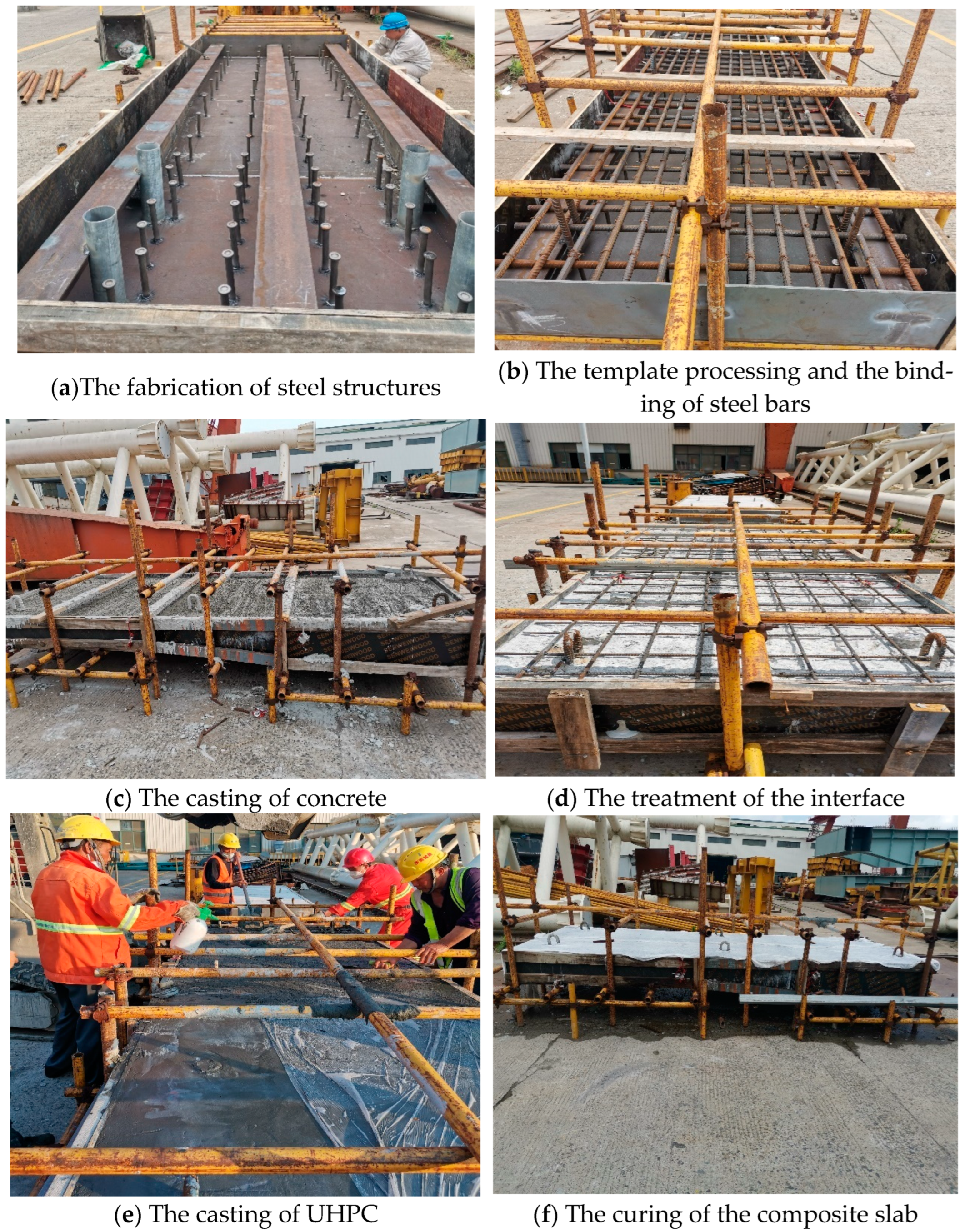
The composite slab was built in a factory, involving five steps: (1) welding and installing the steel structure; (2) installing wood formworks and binding steel bars; (3) casting and curing the concrete; (4) chiselling and cleaning the concrete surfaces; (5) casting and curing the UHPC layers. Figure 4 illustrates the whole fabricating process of the composite slab.

2.4. Loading and Testing Methods

A single-point bending scheme was used in the bending test. Figure 5 shows the loading method, the test setup, and the instrumentation. The cantilever end was fixed to the ground with rolled rebars, forming a 2.8 m long cantilever. The load was applied using a hydraulic jack that had a maximum loading capacity of 2000 kN. The real-time load was acquired by a force sensor above the hydraulic jack. A steel box beam was placed on top of the composite slab to evenly disperse the load. The specimen was preloaded with a load of 40 kN to eliminate possible imperfections in the test facilities. The formal loading adopted monotonic procedures, and loading was carried out with 40 kN each time. The test was stopped when the load could not be increased or began to decrease. During each loading step, the load was maintained for five minutes to allow for stable deformation and crack development.
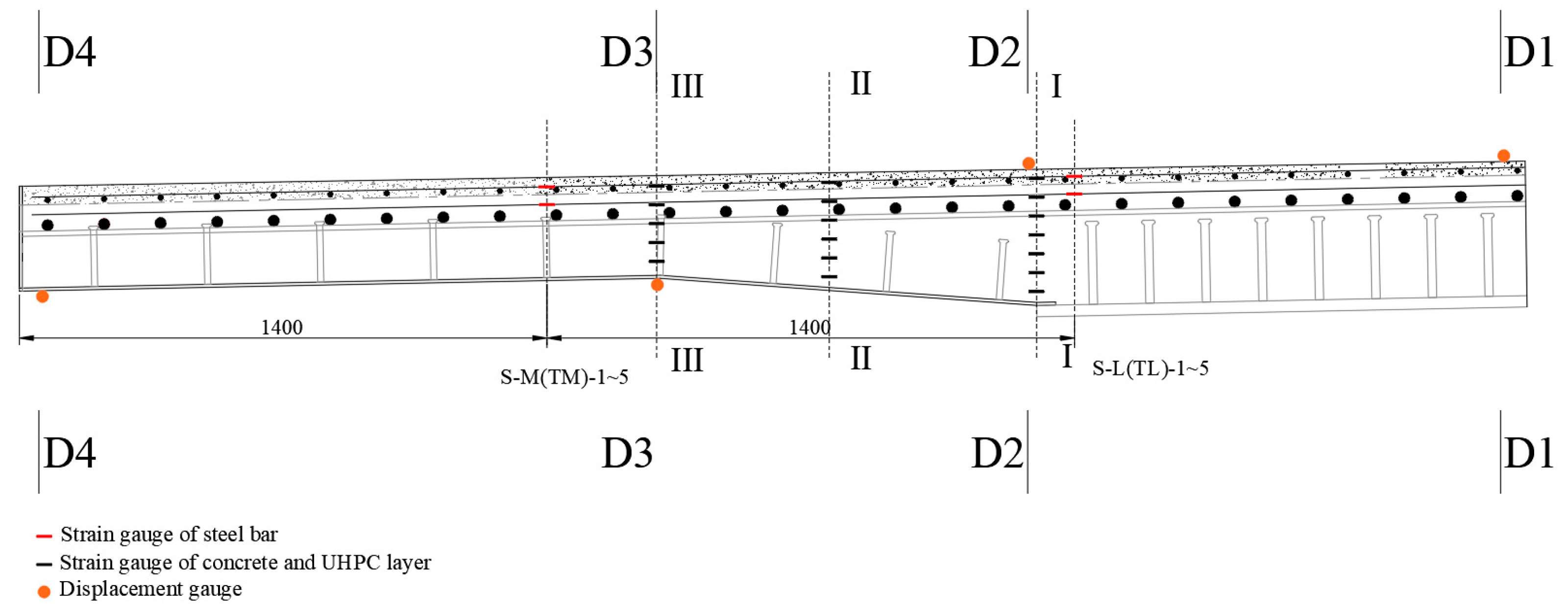
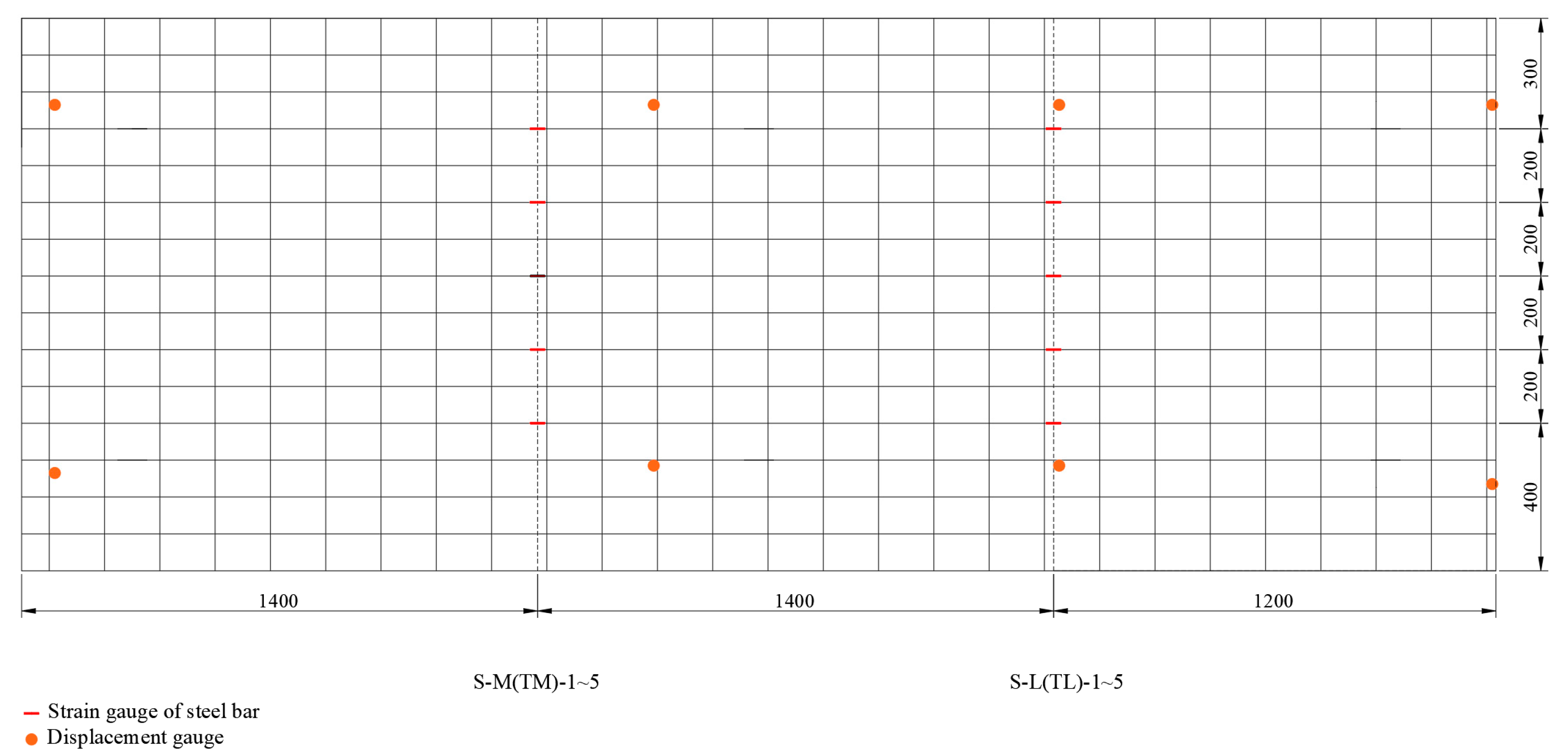
Regarding measuring instruments, linear variable differential transducers (LVDTs) were installed to record the vertical deflections at distances of 2.8 m, 1.1 m, 0.1 m, and −1.2 m from the fixed end. Electronic strain transducers were attached to the side surfaces of the concrete and UHPC layer and inner steel bars, as shown in Figure 6 and Figure 7.

3. Numerical Modelling

In this paper, the finite element software Abaqus 2020 was used to analyse the flexural performance of the steel–NC–UHPC composite slabs. Considering the size of the structure, a mesh size of 75 mm was adopted. The material properties and interface processing methods in the finite element model are introduced below.

3.1. Materials

3.1.1. Concrete and UHPC

In Abaqus, the Concrete Damaged Plasticity (CDP) model was used to model the nonlinear behaviour of both concrete and UHPC in compression and tension. Stress–strain curves of the concrete under uniaxial tension and compression were derived from the guideline [22]. Equations (1)–(3) give the derivation procedures for the tensile stress–strain relationships of concrete.
σ t = ( 1 d t ) E c
d t = 1 ρ t 1.2 0.2 x 5                 x 1
d t = 1 ρ t α t x 1 1.7 + x                 x > 1
where σ t is the tensile stress, x = ε ε t , r , ρ t = f t , r E c ε t , r , f t , r is the uniaxial tensile strength of concrete, f t , r = 2.69   MPa , ε t , r is the tensile strain of concrete corresponding to f t , r , ε t , r = 134.12   μ ε , and α t is the coefficient [22] which is related to the tensile stress.
σ c = 1 d c E c
d c = 1 ρ c n n 1 + x n                 x 1
d c = 1 ρ c α c x 1 2 + x                 x > 1
where σ c is the compressive stress, ρ c = f c , r E c ε c , r , n = E c ε c , r E c ε c , r f c , r , x = ε ε c , r , f c , r is the uniaxial compressive strength, f c , r = 32.88   MPa ε c , r is the compressive strain of concrete corresponding to f c , r , ε c , r = 1686.13   μ ε , and α c is the coefficient [22] which is related to the compressive stress.
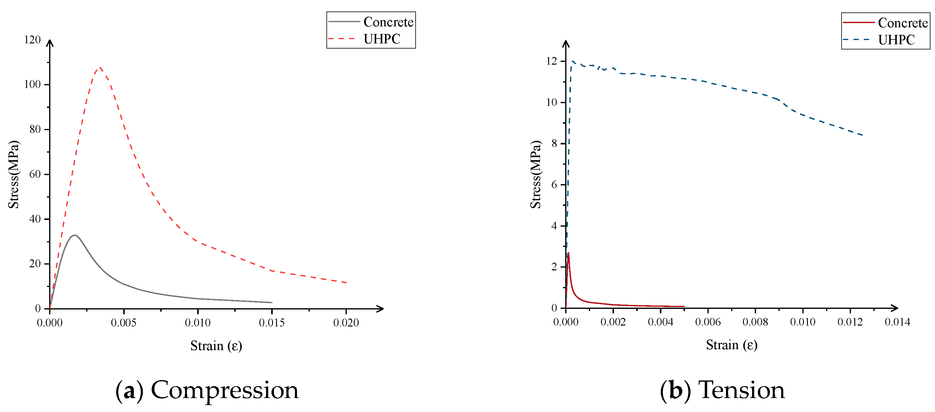
The uniaxial compression stress–strain curve of UHPC proposed by Yang, J. [23] was adopted. Equation (7) gives the calculated procedures for the compressive stress–strain relationships of UHPC. It should be noted that the ultimate compressive strength of UHPC in Equation (7) was determined through the material’s characterization tests. The tensile stress and strain relationship of UHPC was given according to material tests. Figure 8 shows the stress and strain relationship of concrete and UHPC in compression and tension.
σ = f U C n x x 2 1 + ( n 2 ) x                 0 < x 1 f U C x x + 2 ( x 1 ) 2                 x > 1
where x = ε / ε 0 , ε 0 = 3357   μ ε , f U C is the uniaxial compressive strength of UHPC, f U C = 108.10   MPa , and n is the coefficient of the elastic modulus.
To observe the crack propagation of the composite slab, the damage parameters in tension and compression can be assumed to activate when the peak strength is reached. The compressive and tensile damage parameters of concrete [24] are calculated using Equations (8)–(11), respectively.
ϵ N S C c i n = ϵ σ N S C c / E c
D c = 1 σ c E c 1 ϵ c p l 1 b c 1 + σ c E c 1
D t = 1 σ t f t r
where D c and D t are the compression and tension damage parameter of concrete, respectively; σ c and σ t are the compressive stress and tensile stress of concrete; E c is the elastic modulus of concrete [25], 30,041 MPa; ϵ N S C c i n and ϵ N S C t i n are the inelastic strains corresponding to the compressive stress σ N S C c and the tensile stress σ N S C t of concrete, respectively; and b c is a constant with the range of 0 and 1.
The compressive [24] and tensile damage parameters [26] of UHPC are calculated using Equations (12)–(15), respectively.
ϵ U C c i n = ϵ σ U C c / E U C
ϵ U C t i n = ϵ σ U C t / E U C
D U C c = 1 σ U C c E U C 1 ϵ U C c p l 1 b c 1 + σ U C c E U C 1
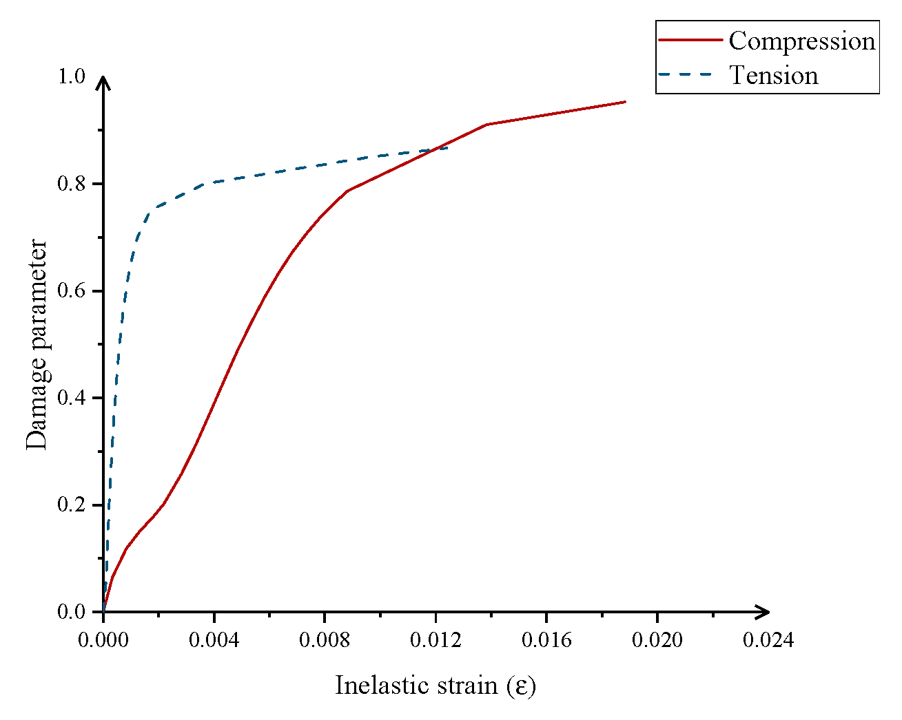
D UC - t = 0.114 + 0.872 1 e ε UC - t in / 5 × 10 4 + 0.185 1 e ε UC - t in / 0.014
Where D U C c and D U C t are the compression and tension damage parameters of UHPC, as shown in Figure 9; σ U C c and σ U C t are the compressive stress and tensile stress of UHPC, respectively; E U C is the elastic modulus of UHPC [25], 41617MPa; ϵ U C c i n and ϵ U C t i n are the inelastic strains corresponding to the compressive stress σ U C c and tensile stress σ U C t , respectively.

3.1.2. Steel Reinforcements and Steel Plate

HRB400E-grade steel bars were used for the reinforcements in this test. The yield strength of the reinforcements was the one obtained in the tests (see Table 2). All reinforcements had the same elastic modulus of 200 GPa and Poisson’s Ratio of 0.3. The elastic modulus and Poisson’s Ratio of the studs and steel ribs were the same as that of the reinforcements.

3.2. Element Selection

The finite element model of the composite slabs included the steel plate, steel reinforcements, concrete slabs, and UHPC layer. The concrete, UHPC layer, and studs were built by the 3-D 8-node reduced integration element C3D8R, while the steel reinforcements embedded in the composite slabs were simulated by the linear truss element T3D2. The steel plate and the steel ribs were simulated by the 4-node reduced integration element S4R.

3.3. Interface and Boundary

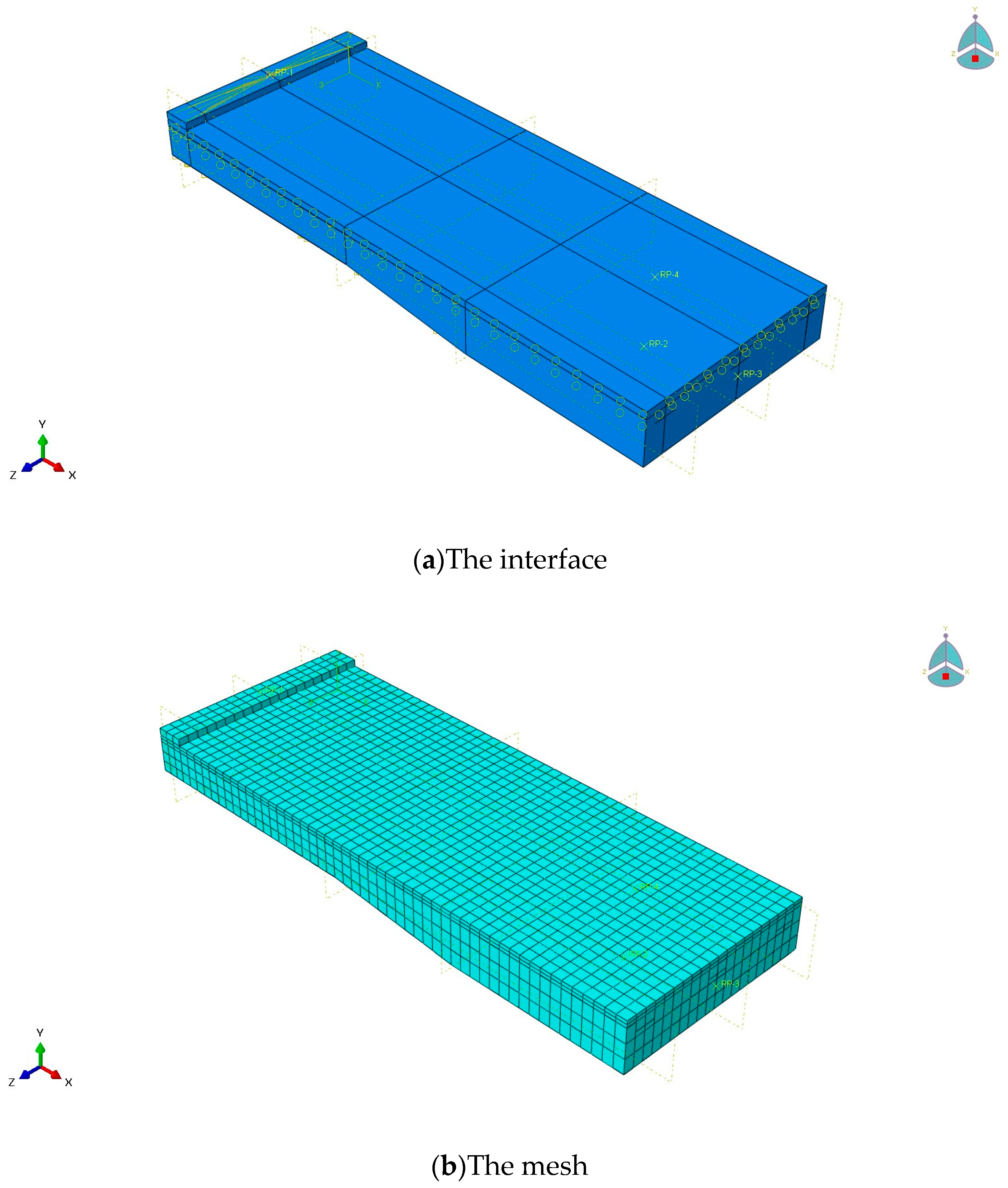
In Abaqus, the studs and steel plates were tied to simulate the welding behaviour between them. The embedding method was used to model the connection between the studs and concrete. The connection of the steel plate and concrete was simulated with surface-to-surface contact. The friction coefficient was taken as 0.2. As for the UHPC-NC interface, cohesive contact was used to simulate the behaviour of the interface. According to reference [27], the normal nominal stiffness k n n and the tangential nominal stiffness k s s , k t t of the cohesion surface were 1.358 MPa/mm, 20.358 MPa/mm, and 20.358 MPa/mm. The viscosity coefficient was defined as 0.001, the ultimate strength ( t n 0 , t s 0 , t t 0 ) was 5.63 MPa, and the ultimate plastic displacement δ n f was 0.241 mm. The steel reinforcements and the steel ribs were embedded in the concrete and UHPC layer. The backing plates were set to avoid stress concentration at the loading position. Additionally, the fixed support was placed at the cantilever end, where UX, UY, and UZ were fixed to simulate the restrictions. The finite model of the composite slabs is shown in Figure 10.

3.4. Construction Methods

In the finite element models, composite slabs constructed with two methods were simulated and analysed. The first one was the scaffolding construction. The composite slab was initially cast and cured on the supports. Then, the specimen was transported to the laboratory, where it was cured for 28 days. The self-weight was supported by the composite slab. The second method was to cast and cure the concrete and UHPC on the steel plate. The steel plate served as the formwork. The self-weight of the concrete and UHPC was supported by the steel plate. Before experiments, the concrete and UHPC were in a zero-stress state. The initial stress of the steel plate was ignored in the finite element model. The characteristics of the two construction methods are summarized in Table 3.

4. Results and Analysis

4.1. Load–Deflection Curves

The load–deflection curves of the composite slabs are shown in Figure 11. As observed from Figure 11, the mechanical behaviour of the composite slab includes four phases under loading: (1) Elastic phase I from the beginning to the cracking of the concrete: the UHPC, concrete, steel bars, and steel plate worked as a unit, accompanied by a nearly linear relationship between the load and deflection. (2) Elastic–plastic phase I from the cracking of the concrete to the cracking of the UHPC layer: in this phase, the stiffness of the composite slabs exhibited a slight decrease, and the deflection increased nearly linearly with the increase in load. (3) Elastic–plastic phase II from the cracking of the UHPC to the yield of the steel bars: in this phase, there was an evident decrease in stiffness. The deflection developed slowly with the load, which demonstrated excellent ductility of the composite slabs. (4) Failure phase: with the increase in displacement, the load nearly remained constant and began to decrease. To clearly reflect the effects of UHPC on the bending performance, the finite element models of the steel–concrete composite slabs were built. The characteristics of the experimental specimen and finite element models are shown in Table 4.
As can be seen from Figure 11, the results of the finite element analysis are relatively consistent with that of the test specimen, especially in the initial phase and the ultimate state. The cracking forces of the UHPC in the finite element models are higher than that of the test specimen. This may be attributed to the defects of UHPC. Additionally, non-uniformity and randomness in the distribution of aggregates influence the mechanical performance of concrete and UHPC. The bearing capacities of the finite element model and experimental specimen are close according to Table 5, whose error is 5.96%.
The finite element models of the steel–NC composite slab were built to determine the enhancing effects of the UHPC layer. The effects of UHPC and the construction methods on the carrying capacity and cracking force were compared and analysed. From Table 6 and Figure 12, it can be seen that the construction method significantly impacts the cracking force of concrete and UHPC. For composite slabs with a full-span scaffolding construction, the cracking force of the concrete decreases from 91 kN to 69 kN compared with construction without brackets. But the construction method does not obviously change the bearing capacity. Comparing the mechanical performance of the A-2-FEM and A-1-FEM model, a 50 mm thick UHPC layer makes the bending and bearing capacity of a steel–NC composite slab increase by 13.51%. Similarly, the cracking force of concrete exhibits an evident improvement, increasing from 44 kN to 91 kN. The change is consistent in the A-2-FEM (self-weight) and A-1-FEM (self-weight) models.

4.2. Cracking Pattern

In the ultimate state, the distribution of cracks in the composite slab are shown in Figure 13. The cracking characteristics of the steel–NC–UHPC composite slabs were different from that of the steel–NC composite slabs. The stress of the UHPC and concrete in the same position is different owing to the difference in mechanical characteristics. The UHPC-NC interface has the function of load transfer and becomes a weak link in the meantime. The failure process of the composite slab can be described as follows: Firstly, concrete near the UHPC-NC interface cracked. Then, the cracks gradually developed along the interface with the increase in load. The distribution of cracks was even, and the width was small at that time. When the tensile stress reached the tensile resistance of the UHPC, the UHPC layer started to crack. Next, with the load continuing to increase, the top steel bars gradually entered the yielding state. The cracks quickly grew wider. Finally, the UHPC layer was pulled off in the variable section of the composite slab. There were three evident cracks in the UHPC layers, which indicated the flexural failure of the composite slabs.
Normally, the top layer of composite slabs should crack prior to other positions. However, the concrete around the UHPC-NC interface cracked before the UHPC layer, based on Figure 13. This is mainly attributed to the difference in the mechanical performances of UHPC and concrete. For the specimens in this test, the tensile strength of the concrete was relatively lower. Thus, the concrete around the interface reached the tensile strength first. But the rate of crack propagation in the concrete layer was slower owing to the influence of the UHPC layer. In the ultimate state, the fracture of the UHPC layer occurred, which indicated that the tensile performance of the UHPC was fully utilized. Additionally, there was no evident slip of the UHPC-NC interface before failure, indicating the reliability of the rough interface.

4.3. Strain History

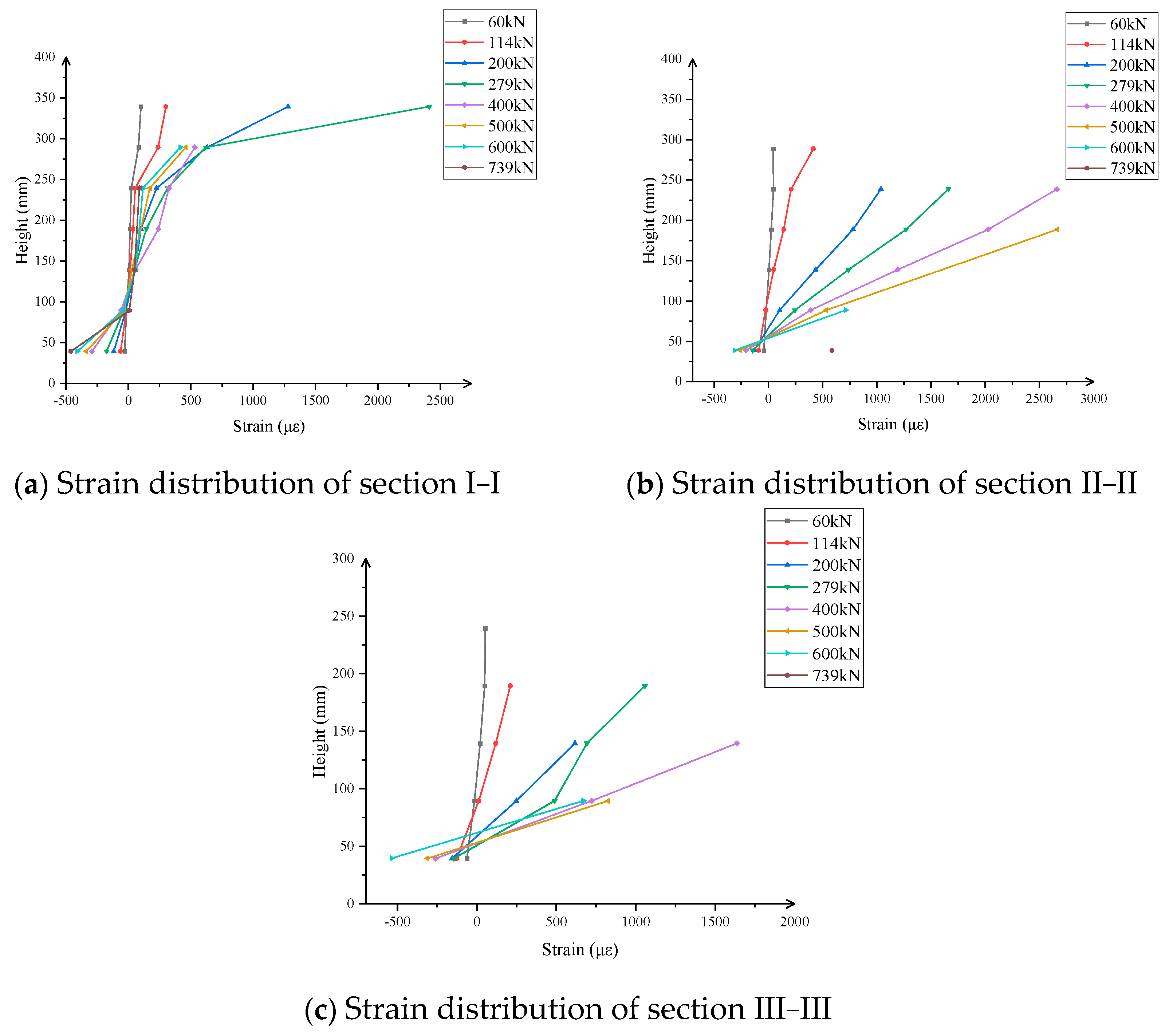
The strain distribution along the height of the section of the composite slab under loading is shown in Figure 14. The positive and negative strains represent tension and compression, respectively. The strain distribution along the height of the section of the composite slabs basically satisfied the plane section assumption before UHPC cracking. After UHPC cracking, the UHPC began to enter the plastic state, and fibres started to prevent the development of cracks. However, the composite slabs except for the UHPC layer basically met the plane section assumption before failure, as indicated in Figure 14.
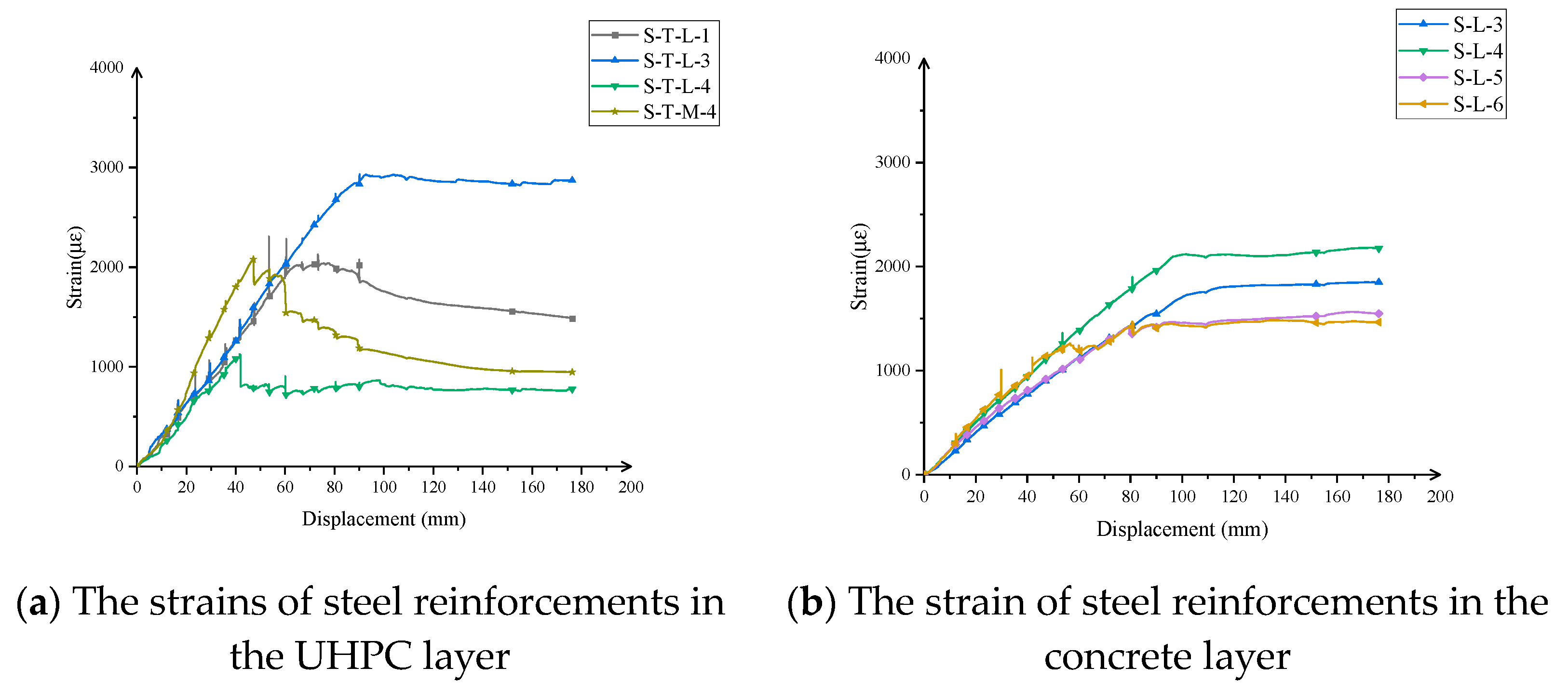
The strain–displacement curves of the steel bars are shown in Figure 15. In the ultimate state, the maximum strains of the steel bars were above 2000 μ ε , which indicated that the steel bars had entered the yielding state. Additionally, the maximum strain of the steel bars in the UHPC layer was higher than that of the steel bars in the concrete layer. This may be mainly owing to the larger crack width of the UHPC layer compared to the concrete.

5. Theoretical Analysis

5.1. Cracking Resistance and Bearing Capacity

As mentioned previously in this paper, the failure process of the composite slabs includes four phases. During the loading process, the specimen basically satisfies the plane section assumption. Firstly, the bending moment of the composite slabs corresponds to concrete cracking, and UHPC cracking and the ultimate state can be determined based on the plane section assumption.
In general, UHPC is designed to crack prior to concrete. However, concrete cracks should be allowed to appear first when the cracking load meets the design requirement for composite slabs. If the requirement that UHPC cracking is prior to concrete must be met, the engineering costs may increase significantly owing to the use of more UHPC. This may result in a waste of materials to some degree. Thus, the balance between the costs and effects of UHPC should be maintained and controlled in the engineering process.
(1)
The initial cracking of concrete
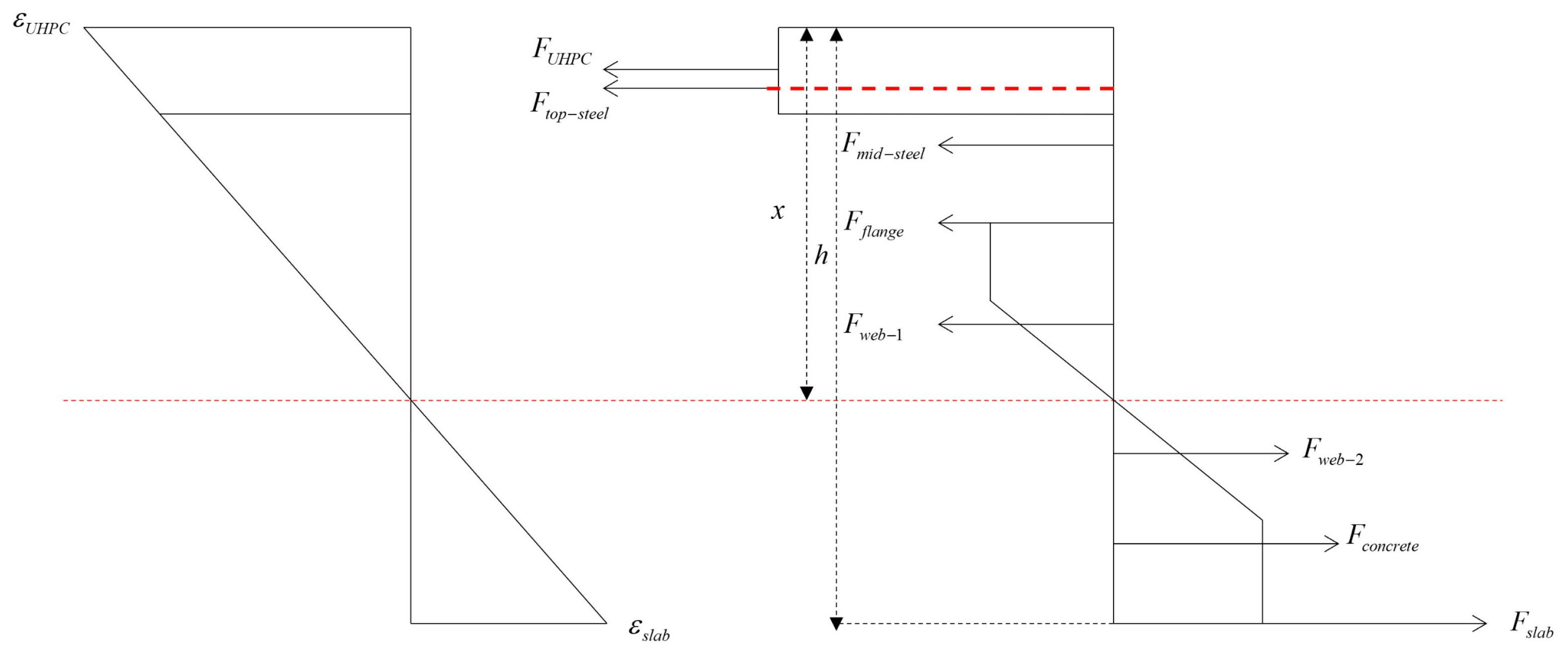
The composite slab first cracks when the tensile stress reaches the tensile resistance of concrete. According to the plane section assumption, the strains of concrete and other components of the composite slab can be calculated. At this time, the distribution of the strain and force along the section is shown in Figure 16.
ε N S C = σ N S C / E N S C
tan θ = ε N S C x h U H P C
where ε N S C is the cracking strain of concrete; σ N S C is the tensile stress of concrete; E N S C is the elastic modulus of concrete; x is the height of the neutral axis; and h U H P C is the height of the UHPC layer.
Thus, the force of all components can be given based on the plane section assumption.
F U H P C = E U H P C tan θ ( x h U H P C + h U H P C ( 2 ε N S C + ε U H P C ) / 3 / ( ε N S C + ε U H P C ) ) A U H P C
F t o p s t e e l = ε t o p s t e e l E S A t o p s t e e l
F m i d s t e e l = ε m i d s t e e l E S A m i d s t e e l
F f l a n g e = ε f l a n g e E S A f l a n g e
F w e b 1 = ε w e b 1 E S A w e b 1
F w e b 2 = ε w e b 2 E S A w e b 2
F c o n c r e t e = ε c o n c r e t e E N S C A c o n c r e t e
F s l a b = ε s l a b E S A s l a b
where F U H P C is the resulting force of the UHPC layer, E U H P C is the elastic modulus of UHPC, ε U H P C is the strain of UHPC, A U H P C is the area of the UHPC layer, F t o p s t e e l is the resulting force of the top steel reinforcements, ε t o p s t e e l is the strain of the top steel reinforcements, E S is the elastic modulus of the steel reinforcements, A t o p s t e e l is the area of the steel reinforcements in the UHPC, F m i d s t e e l is the resulting force of the steel reinforcements in the concrete, ε m i d s t e e l is the strain of the steel reinforcements in the concrete, A m i d s t e e l is the area of the steel reinforcements in the concrete, F f l a n g e is the resulting force of the flange of the steel ribs, ε f l a n g e is the strain of the flange of the steel ribs, A f l a n g e is the area of the flange of the steel ribs, F w e b 1 is the resulting force of the web of steel ribs above the neutral axis, ε w e b 1 is the maximum strain of the web of steel ribs above the neutral axis, A w e b 1 is the area of the web of steel ribs above the neutral axis, F w e b 2 is the resulting force of the web of steel ribs below the neutral axis, ε w e b 2 is the strain of the web of steel ribs below the neutral axis, A w e b 2 is the area of the web of steel ribs below the neutral axis, F c o n c r e t e is the resulting force of the compressive concrete, ε c o n c r e t e is the maximum strain of the compressive concrete, and A c o n c r e t e is the area of the compressive concrete.
The height of the neutral axis can be determined according to the force equilibrium (Equation (26)).
F U H P C + F t o p s t e e l + F m i d s t e e l + F f l a n g e + F w e b 1 = F w e b 2 + F c o n c r e t e + F s l a b
The flexural moment of the composite slab can be given using Equation (27).
M = F U H P C h U H P C 1 + F t o p s t e e l h t o p s t e e l + F m i d s t e e l h m i d s t e e l + F f l a n g e h f l a n g e + F w e b 1 h w e b 1 + F w e b 2 h w e b 2 F c o n c r e t e h c o n c r e t e F s l a b h s l a b
The concentrated force at the end of the composite slab can be calculated using Equation (28).
F = M / l
where h U H P C 1 , h t o p s t e e l , h m i d s t e e l , h f l a n g e , h w e b 1 , h c t 1 , h c t 2 , h w e b 2 , h c o n c r e t e , and h s l a b are the distance from each component to the bottom of the composite slabs, and l is the distance from the support to the loading point.
(2)
The initial cracking of UHPC
When the tensile stress in the UHPC layer reaches the tensile resistance of UHPC, the cracks will occur in the UHPC layer. Similarly, the strains of UHPC and other components of composite slabs can be determined based on the plane section assumption. The height of the neutral axis can be calculated with the same methods as above. The distribution of the strain and force along the section is shown in Figure 17.
ε U H P C = σ U H P C / E U H P C
tan φ = ε U H P C x
The height of the neutral axis and the bending moment of the composite slabs can be calculated with reference to Equations (27) and (28).
(3)
The ultimate state
In the ultimate state, the UHPC layer is pulled off, and local buckling of the steel plate occurs. The steel bars in the UHPC layer and concrete layer yield, as shown in Figure 15. The bearing capacity of the composite slab can be calculated based on the following assumptions:
The assumptions are that (1) the specimens basically meet the plane section assumption before failure; (2) the steel bars and the flange of the steel ribs yield in the ultimate state; and (3) the effects of cracking of the UHPC layers are considered.
Before the failure of composite slabs, a cracking UHPC layer still undertakes the bending resistance owing to the effects of fibres. The tensile residual stress of cracking UHPC layer is determined as [28]
σ t = 0.304 f U , c u ρ f l f d f
where σ t is the tensile residual stress of cracking UHPC, f U , c u is the compressive strength of UHPC, ρ f is the fibre volume fraction, l f is the length of the fibres, and d f is the diameter of and fibres.
The position of the neutral axis of the section is in the web of steel ribs. At this time, the distribution of the strain and force along the section is shown in Figure 18.
The height of the neutral axis can be calculated using Equation (32).
F U H P C + F t o p s t e e l + F m i d s t e e l + F f l a n g e + F w e b 1 = F w e b 2 + F c o n c r e t e + F s l a b
The flexural moment of the composite slab can be given using Equation (33).
M u = F U H P C h U H P C + F t o p s t e e l h t o p s t e e l + F m i d s t e e l h m i d s t e e l + F f l a n g e h f l a n g e + F w e b 1 h w e b 1 F w e b 2 h w e b 2 F c o n c r e t e h c o n c r e t e F s l a b h s l a b
The bearing capacity of the composite slabs can be calculated with Equation (34).
F = M u / l

5.2. Verification and Comparison

Table 7 summarizes the experimental and theoretical calculation results of the cracking force and the ultimate load of the composite slab. As shown in Table 7, the error of the theoretical bending carrying capacity and experimental values is 9.47% when the tensile contribution of cracking UHPC is considered. The theoretical bending capacity is lower than the experimental value, which makes the composite slabs safer in service.
Additionally, the error of the theoretical cracking forces and experimental values of concrete and UHPC are initially −9.68% and 32.86%. In the case of the concrete cracking first, the error is relatively small. In the case of the UHPC layer cracking first, the error is relatively high, which may mainly be attributed to the fact that the theoretical model ignores the interface slip between the concrete and UHPC.

6. Conclusions

This paper presents a study on the flexural performance of steel–normal concrete–UHPC composite slabs with experiments, numerical simulation, and theoretical analysis. The following conclusions are drawn:
(1)
The use of UHPC enhances the flexural performance of composite slabs, such as the cracking force and bearing capacity. Based on experiments and finite element analysis, a 5 mm UHPC layer made the bearing capacity of steel concrete composite slabs increase by 13.51%. The cracking forces of concrete and UHPC layers are clearly enhanced.
(2)
UHPC delays the development of cracks in the concrete and strengthens the tensile contribution of the concrete. For steel–normal concrete–UHPC composite slabs, the cracking force of concrete increases from 44 kN to 91 kN compared with steel–concrete composite slabs, which indicates an evident rise.
(3)
Construction methods have an evident influence on the initial cracking forces of concrete and UHPC layers. The scaffolding construction method reduces the initial cracking force of concrete from 91 kN to 69 kN compared with that of construction without brackets. For the UHPC layer, the impacts of construction methods on the initial cracking force are similar.
(4)
The analytical model proposed in this paper can potentially be used to calculate the cracking force and bearing capacity of steel–normal concrete–UHPC composite slabs. The results of the theoretical model considering the tensile contribution of cracking UHPC are closer to experimental values. The theoretical values are lower than the experimental values, which makes the composite slab safer in service. The theoretical cracking force of the UHPC layer is relatively higher than the experimental values, which may be attributed to material defects and a slight interface slip in the tests.
(5)
The durability of a steel–normal concrete–UHPC composite slab is critical for its application. Thus, the durability of a steel–normal concrete–UHPC composite slab should be studied with more experiments in the future.

Author Contributions

Conceptualization, S.G., X.M. and C.L.; methodology, S.G., X.M. and C.L.; software, S.G.; validation, S.G.; formal analysis, S.G.; investigation, S.G. and X.M.; resources, S.G.; data curation, S.G. and C.L.; writing—original draft preparation, S.G.; writing—review and editing, C.L.; visualization, S.G.; supervision, X.M. and C.L. All authors have read and agreed to the published version of the manuscript.

Funding

This research received no external funding.

Data Availability Statement

No new data were created or analyzed in this study. Data sharing is not applicable to this article.

Conflicts of Interest

Author Xiaogang Ma was employed by the company Shanghai Pudong Architectural Design & Research Institute Co., Ltd. The remaining authors declare that the research was conducted in the absence of any commercial or financial relationships that could be construed as a potential conflict of interest.

References

  1. Viest, I.M. Review of research on composite steel–concrete beams. J. Struct. Div. 1960, 86, 1101–1121. [Google Scholar] [CrossRef]
  2. Nie, J.; Wang, J.; Gou, S.; Zhu, Y.; Fan, J. Technological development and engineering applications of novel steel-concrete composite structures. Front. Struct. Civ. Eng. 2019, 13, 1–14. [Google Scholar] [CrossRef]
  3. Amran, M.; Huang, S.S.; Onaizi, A.M.; Makul, N.; Abdelgader, H.S.; Ozbakkaloglu, T. Recent trends in ultra-high performance concrete (UHPC): Current status, challenges, and future prospects. Constr. Build. Mater. 2022, 352, 129029. [Google Scholar] [CrossRef]
  4. Shafieifar, M.; Farzad, M.; Azizinamini, A. Experimental and numerical study on mechanical properties of Ultra High Performance Concrete (UHPC). Constr. Build. Mater. 2017, 156, 402–411. [Google Scholar] [CrossRef]
  5. Zhou, M.; Lu, W.; Song, J.; Lee, G.C. Application of ultra-high performance concrete in bridge engineering. Constr. Build. Mater. 2018, 186, 1256–1267. [Google Scholar] [CrossRef]
  6. Brühwiler, E.; Denarié, E. Rehabilitation and strengthening of concrete structures using ultra-high performance fibre reinforced concrete. Struct. Eng. Int. 2013, 23, 450–457. [Google Scholar] [CrossRef]
  7. Rokugo, K. Recommendations for Design and Construction of High Performance Fiber Reinforced Cement Composites with Multiple Fine Cracks (HPFRCC); Japan Society of Civil Engineers, Concrete Committee: Tokyo, Japan, 2008. [Google Scholar]
  8. Cement, Ultra-High Performance Fibre Reinforced. Based Composites (UHPFRC)-Construction Material, Dimensioning and Application; EPFL-Swiss Federal Institute of Technology: Vaud, Switzerland, 2016. [Google Scholar]
  9. NF P18-470; Concrete-Ultra-High Performance Fibre-Reinforced Concrete–Specifications, Performance, Production and Conformity. Association Française de Normalisation: La Plaine Saint-Denis, Francie, 2016.
  10. Wan, Z.; Fang, Z.; Liang, L.; He, S.; Sun, X. Structural performance of steel–concrete composite beams with UHPC overlays under hogging moment. Eng. Struct. 2022, 270, 114866. [Google Scholar] [CrossRef]
  11. Lu, W.-L.; Peng, W.-Q.; Zhu, L.; Ma, B.; Li, F.-L. Study on mechanical behavior of steel-UHPC-NC composite beams under negative bending moment. Case Stud. Constr. Mater. 2022, 17, e01593. [Google Scholar] [CrossRef]
  12. Yin, H.; Shirai, K.; Teo, W. Numerical model for predicting the structural response of composite UHPC–concrete members considering the bond strength at the interface. Compos. Struct. 2019, 215, 185–197. [Google Scholar] [CrossRef]
  13. Safdar, M.; Matsumoto, T.; Kakuma, K. Flexural behavior of reinforced concrete beams repaired with ultra-high performance fiber reinforced concrete (UHPFRC). Compos. Struct. 2016, 157, 448–460. [Google Scholar] [CrossRef]
  14. Sadouki, H.; Denarié, E.; Brühwiler, E. Validation of a FEA model of structural response of RC-cantilever beams strengthened with a (R-) UHPFRC layer. Constr. Build. Mater. 2017, 140, 100–108. [Google Scholar] [CrossRef]
  15. Zhu, Y.; Zhang, Y.; Yuan, X.; Hou, C. An Adaptive Crack Width Prediction for Flexural Steel Reinforced UHPC Beam. Int. J. Concr. Struct. Mater. 2023, 17, 73. [Google Scholar] [CrossRef]
  16. Shao, X.; Deng, L.; Cao, J. Innovative steel-UHPC composite bridge girders for long-span bridges. Front. Struct. Civ. Eng. 2019, 13, 981–989. [Google Scholar] [CrossRef]
  17. Luo, J.; Shao, X.; Cao, J.; Xiong, M.; Fan, W. Transverse bending behavior of the steel-UHPC lightweight composite deck: Orthogonal test and analysis. J. Constr. Steel Res. 2019, 162, 105708. [Google Scholar] [CrossRef]
  18. Zhao, C.; Wang, K.; Xu, R.; Deng, K.; Cui, B. Development of fully prefabricated steel-UHPC composite deck system. J. Struct. Eng. 2019, 145, 04019051. [Google Scholar] [CrossRef]
  19. Cheng, Z.; Zhang, Q.; Bao, Y.; Deng, P.; Wei, C.; Li, M. Flexural behavior of corrugated steel-UHPC composite bridge decks. Eng. Struct. 2021, 246, 113066. [Google Scholar] [CrossRef]
  20. Xiao, J.-L.; Zhou, M.; Nie, J.-G.; Yang, T.-Y.; Fan, J.-S. Flexural behavior of steel-UHPC composite slabs with perfobond rib shear connectors. Eng. Struct. 2021, 245, 112912. [Google Scholar] [CrossRef]
  21. Zou, Y.; Zheng, K.; Zhou, Z.; Zhang, Z.; Guo, J.; Jiang, J. Experimental study on flexural behavior of hollow steel-UHPC composite bridge deck. Eng. Struct. 2023, 274, 115087. [Google Scholar] [CrossRef]
  22. GB50010-2010; Code for Design of Concrete Structures. Ministry of Housing and Urban-Rural Development of the People’s Republic of China: Beijing, China, 2011.
  23. Yang, J. Flexural Behavior of Ultra-High Performance Concrete Beams Prestressed with CFRP Tendons; Hunan University: Changsha, China, 2007. [Google Scholar]
  24. Birtel, V.; Mark, P. Parameterised finite element modelling of RC beam shear failure. In Proceedings of the ABAQUS Users’ Conference, Boston, MA, USA, 23–25 May 2006. [Google Scholar]
  25. Alsalman, A.; Walsh, K.K.; Sargand, S.M.; Al Rikabi, F.T.; Steinberg, E.P. Prediction of modulus of elasticity of UHPC using maximum likelihood estimation method. Structures 2022, 35, 1308–1320. [Google Scholar] [CrossRef]
  26. Krahl, P.A.; Carrazedo, R.; El Debs, M.K. Mechanical damage evolution in UHPFRC: Experimental and numerical investigation. Eng. Struct. 2018, 170, 63–77. [Google Scholar] [CrossRef]
  27. Hussein, H.H.; Walsh, K.K.; Sargand, S.M.; Al Rikabi, F.T.; Steinberg, E.P. Modeling the shear connection in adjacent box-beam bridges with ultrahigh-performance concrete joints. I: Model calibration and validation. J. Bridge Eng. 2017, 22, 04017043. [Google Scholar] [CrossRef]
  28. Qi, J.; Wang, J.; Ma, Z.J. Flexural response of high-strength steel-ultra-high-performance fiber reinforced concrete beams based on a mesoscale constitutive model: Experiment and theory. Struct. Concr. 2018, 19, 719–734. [Google Scholar] [CrossRef]
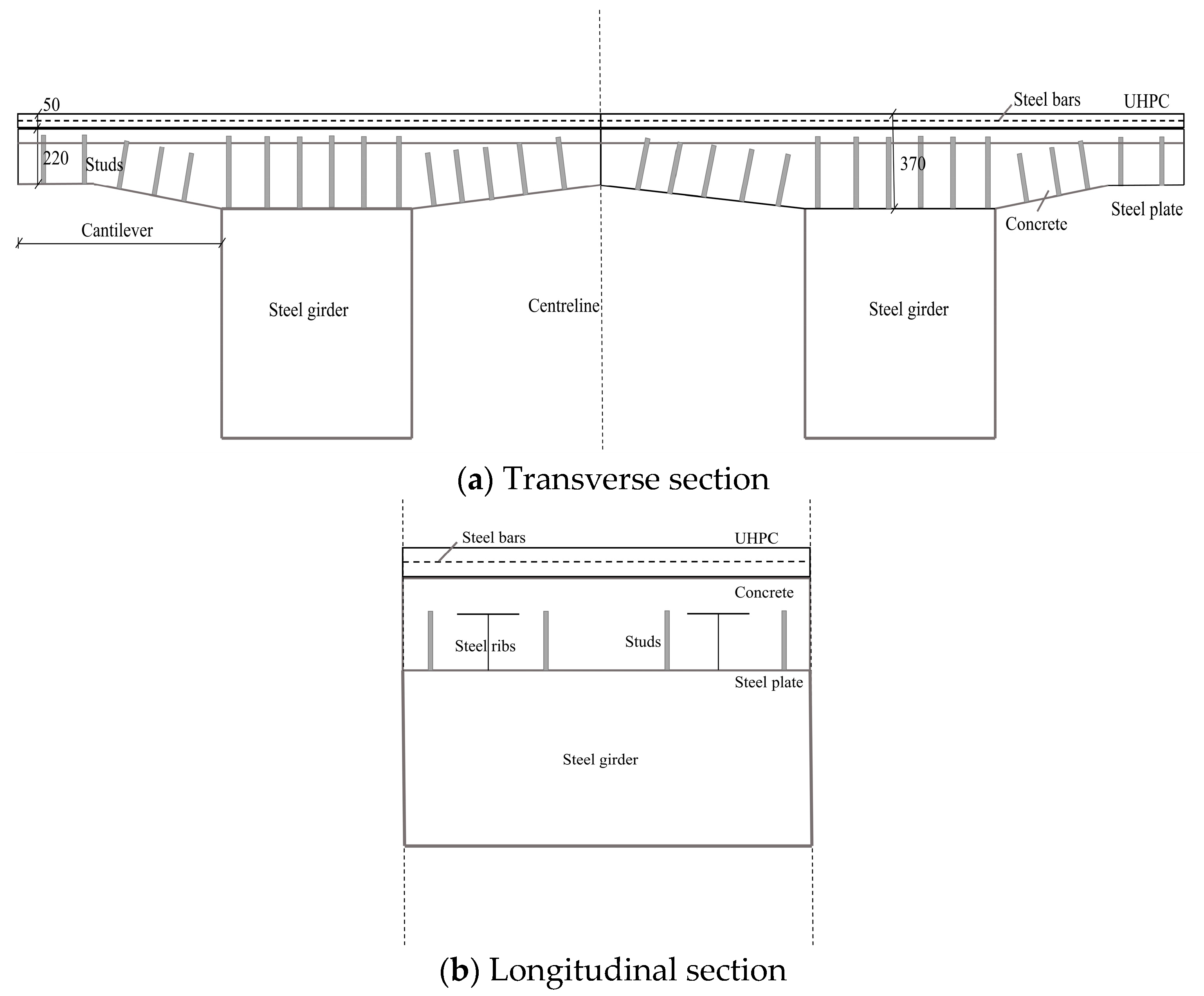
Figure 1. Schematic section of steel–normal concrete–UHPC composite bridges (unit: mm).
Buildings 14 01301 g001
Figure 2. Lateral view of the composite slab specimen (unit: mm).
Buildings 14 01301 g002
Figure 3. Front view of the composite slab specimen (unit: mm).
Buildings 14 01301 g003
Figure 4. Specimens’ production process.
Buildings 14 01301 g004
Figure 5. Experimental diagram of single-point loading.
Buildings 14 01301 g005
Figure 6. The lateral view of the distribution of strain transducers and displacement transducers (unit: mm).
Buildings 14 01301 g006
Figure 7. The top view of the distribution of strain transducers and displacement transducers (unit: mm).
Buildings 14 01301 g007
Figure 8. Uniaxial stress–strain curves of UHPC and concrete.
Buildings 14 01301 g008
Figure 9. Damage parameter–inelastic strain curves of UHPC.
Buildings 14 01301 g009
Figure 10. Finite element model of the composite slabs.
Buildings 14 01301 g010
Figure 11. The load–displacement curves of the composite slabs.
Buildings 14 01301 g011
Figure 12. The load–displacement curves of the composite slabs with different construction methods.
Buildings 14 01301 g012
Figure 13. The distribution of cracks in the ultimate state.
Buildings 14 01301 g013
Figure 14. The strain distribution of sections, along with the slab height.
Buildings 14 01301 g014
Figure 15. The curves of the strain and displacement of steel bars.
Buildings 14 01301 g015
Figure 16. The strain and force distribution of the section when concrete the cracks first.
Buildings 14 01301 g016
Figure 17. The strain and force distribution of the section when UHPC cracks first.
Buildings 14 01301 g017
Figure 18. The strain and force distribution diagram of composite slabs in the ultimate state.
Buildings 14 01301 g018
Table 1. Components of the UHPC.
MaterialsWater (kg/m3)Premix (kg/m3)Steel Fibres (kg/m3)Admixture (kg/m3)
UHPC/m3177.302221.65200.0019.50
Table 2. Yield and tensile strength of steel.
TypeDiameter/Height (mm)Yield Strength (MPa)Tensile Strength (MPa)
Q355B8383.0532.0
20435.0580.0
HW350350389.0557.8
HRB400E25447.5617.5
12437.5597.5
ML1516 × 180--418.0
22 × 200--465.0
Table 3. The characteristics of the two construction methods for composite slabs.
Construction MethodsCharacteristics
Scaffolding constructionInitially, the self-weight of composite slabs is supported by the supports; before loading, composite slabs bear their own weight. Then, the UHPC layer and concrete are in a tensile state owing to their self-weight.
Construction without bracketsFirstly, the self-weight of the UHPC and concrete is supported by the bottom steel slabs; before loading, the UHPC layer and concrete are in a zero-stress state.
Table 4. The experimental specimen and finite element models.
SpecimensComponentsConstruction MethodsClassification
A-1-TestSteel–NC–UHPC composite slabScaffolding constructionExperimental specimens
A-1-FEM (self-weight)Steel–NC–UHPC composite slabScaffolding constructionFinite element model
A-1-FEMSteel–NC–UHPC composite slabConstruction without bracketsFinite element model
A-2-FEMSteel–NC composite slabConstruction without bracketsFinite element model
A-2-FEM (self-weight)Steel–NC composite slabScaffolding constructionFinite element model
Table 5. Cracking load and ultimate load of the composite slabs.
SpecimensCracking Load of Concrete (kN)Cracking Load of UHPC (kN)Ultimate Load (kN)Error (%)
A-1-Test6270727--
A-1-FEM (self-weight)69117683−5.96
Table 6. Cracking load and ultimate load of the composite slabs under different construction methods.
SpecimensCracking Load of Concrete (kN)Cracking Load of UHPC Layer (kN)Ultimate Load (kN)Increasing Ratio (%)
A-2-FEM44--609--
A-1-FEM9113369113.51
A-2-FEM (self-weight)29--594--
A-1-FEM (self-weight)6911768315.10
Table 7. The comparison of the theoretical calculation results and experimental values.
SpecimensCracking Load of Concrete (kN)Cracking Load of UHPC (kN)Ultimate Bearing Capacity (kN)
A-1-Test6270727
A-1-I5693658
(Note: A-1-Test: steel–NC–UHPC composite slab test specimen; A-1-I: theoretical model considering the tensile contribution of UHPC.)
Disclaimer/Publisher’s Note: The statements, opinions and data contained in all publications are solely those of the individual author(s) and contributor(s) and not of MDPI and/or the editor(s). MDPI and/or the editor(s) disclaim responsibility for any injury to people or property resulting from any ideas, methods, instructions or products referred to in the content.