Article

Triaxial Test and Discrete Element Numerical Simulation of Geogrid-Reinforced Clay Soil

by
Xi Wang
1,
Qizhi Hu
1,2,*,
Yiming Liu
1 and
Gaoliang Tao
1,2
1
School of Civil Architecture and Environment, Hubei University of Technology, Wuhan 430068, China
2
Hubei Bridge Safety Monitoring Technology and Equipment Technology Engineering Research Center, Wuhan 430068, China
*
Author to whom correspondence should be addressed.
Buildings 2024, 14(5), 1422; https://doi.org/10.3390/buildings14051422
Submission received: 24 April 2024 / Revised: 8 May 2024 / Accepted: 13 May 2024 / Published: 15 May 2024
(This article belongs to the Section Building Energy, Physics, Environment, and Systems)

Abstract

:
Indoor triaxial tests on geogrid-reinforced clay elucidate the macroscopic changes in soil strength indices post-reinforcement, yet the underlying mechanisms of strength enhancement require further investigation. By conducting indoor triaxial tests and establishing a corresponding discrete element numerical model, we can delve into the fine-scale mechanisms of geogrid-reinforced soil. This includes analyzing changes in fine-scale parameters such as porosity, the coordination number, and contact stress between soil particles. The findings suggest that an increase in the number of geogrid reinforcement layers leads to a more pronounced improvement in peak strength and cohesion, albeit with minimal impact on the internal friction angle of the specimens. Furthermore, analysis of the triaxial test curves of reinforced soils indicates that the stress–strain relationship adheres to the Duncan–Chang model. Parameters derived from this model have been validated against experimental data, confirming their accuracy. The discrete element model was used to analyze the variations in fine-scale parameters such as porosity and coordination number. It revealed that reinforcement reduces the fluctuation amplitude of porosity and significantly increases the number of particle contacts, resulting in a denser soil structure. Further analysis of the change in contact stress between particles in the discrete element model revealed that the contact force between particles increased significantly after reinforcement and that the reinforcement played a role in restraining the soil particles and dispersing the reinforcement stress, which explains the increase in the strength of the mesh-reinforced clays from another perspective. This further elucidates the strength enhancement mechanism in geogrid-reinforced clay, offering a new perspective on the mechanical behavior and strength development of such materials.

1. Introduction

Reinforced soil technology, characterized by its high construction efficiency, safety, and cost-effectiveness, is extensively utilized in urban construction, highways, and railway projects [1,2,3]. Geogrids, widely used as reinforcing materials in current reinforced soil engineering, exhibit excellent corrosion resistance, high strength, and effective interlocking with soil, providing a reliable enhancement to reinforced soil structures [4]. Traditionally, backfill materials for reinforced soil have typically comprised crushed rock or sandy soils. However, recent projects have successfully employed local clays as fill materials, prompted by factors such as geological conditions, transport logistics, and economic considerations, thereby drawing increased attention to clays as viable engineering fill materials [5,6]. Nonetheless, compared to traditional backfill materials like sandy soils, studies on clay reinforcement are relatively sparse. Research into the mechanical properties of geogrid-reinforced clay is of significant theoretical value and practical importance for understanding the mechanisms of reinforcement and for the design and implementation of reinforced soil structures.
Indoor tests such as the straight shear test, the pull-out test, and the triaxial test are commonly employed to examine the mechanical properties of geogrid-reinforced soil. Jiantao Cai explored the interaction at the reinforcement–soil interface by subjecting geogrid-reinforced expanded soil to various vertical loads during pullout tests [7]. M. R. Abdi et al. investigated the impact of the geogrid type and coarse particle size on the pullout characteristics of reinforced soil [8]. Venkata Abhishekd et al. conducted large-scale direct shear tests on geogrid-reinforced soils, finding that the aperture area of the geogrid and the strength of the connection significantly influence the shear strength response at the soil–aggregate interface [9]. Wang Jiaquan et al. developed a large-scale visual straight shear test apparatus, adaptable to various working conditions. This innovation opens new avenues for exploring the properties of the reinforced–soil interface and the mechanisms of reinforcement force, as well as analyzing reinforcement displacement [10]. Triaxial testing, which simulates the actual stress state of soil more effectively [11,12], is based on the principles of equivalent perimeter pressure and quasi-viscous cohesion [13,14]. Scholars employing this method have documented significant findings regarding the mechanical properties of reinforced soils. Zakarka et al. conducted studies on geogrid-reinforced coarse-grained soils through triaxial testing and observed that increasing perimeter pressure reduces the effectiveness of geogrid reinforcement [15,16]. Xiaobin et al. investigated the shear performance of such soils reinforced with geogrids using large-scale triaxial tests, revealing that geogrids significantly enhance viscous cohesion. The study further emphasized that the number of geogrid layers influences the interfacial interactions between the geogrid and the soil [17].
Luo Zhaogang conducted a series of indoor triaxial compression tests to analyze the influence of geogrid reinforcement layers, initial moisture content, and perimeter pressure on the strength and deformation characteristics of reinforced coral sand [18]. Cai, Y. et al. performed large-scale triaxial tests under graded cyclic loading to explore the dynamic properties and mechanisms of geogrid-reinforced rubber crushed stone composites [19]. Akshit et al. assessed the shear characteristics of landfill clay overlaid with geogrid through triaxial compression testing, finding that geogrid incorporation enhances ductility and curtails the development of tensile cracks [20].
Wang et al. conducted large-scale triaxial tests to assess the impact of vertical spacing of geogrids, the number of reinforced layers, cell height, and cell type on the strength and deformation properties of reinforced gravel composites [21]. Song Fei et al. developed and validated a stress–strain response calculation model for geocell-reinforced consolidated clay, using triaxial test results to confirm the model’s accuracy and reliability [22]. Zhao Xiaolong et al. performed conventional triaxial consolidation and drainage shear tests on coarse-grained soil samples with varying geotextile reinforcement layers, exploring the influence of these layers on the soil’s deformation and strength characteristics [23].
Liu Fangcheng et al. conducted triaxial compression tests on dry rubber sand using various geogrid configurations and proportions to explore their strength characteristics [24]. Fu Yi et al. performed triaxial compression tests on tailings reinforced with geogrids and geotextiles. They utilized the Duncan–Chang model to simulate the stress–strain curves under different reinforcement layers. The results demonstrated that cohesion, a critical measure of shear strength, increases linearly with the addition of reinforcement layers, whereas the internal friction angle remains relatively constant [25]. Wang Xiequn et al. explored the impact of varying perimeter pressures on expansive soils reinforced with geogrids through triaxial drainage shear tests. The study demonstrated that geogrid reinforcement plays a crucial role in stabilizing soil slopes by inhibiting the formation of shear zones [26]. Li Xiaojun et al. conducted shear tests on diverse geomaterial-reinforced soils, including gravel, clayey, coarse-grained, and fine-grained variants. The results highlighted that geomaterial reinforcement significantly enhances soil strength and validated the Duncan–Chang model’s utility in depicting the ontological relationships within reinforced soils [27,28,29,30,31].
Indoor tests mainly obtain the response of the macroscopic mechanical properties of reinforced soils, and it is difficult to explore the fine mechanical mechanism of reinforced soils at the particle level. Discrete element numerical simulation, which models soil particles as spheres, allows for the visualization of particle motion by tracking the relative displacements among them [32]. The discrete element numerical simulation allows the particles to move and rotate in a limited way during the simulation process, and its motion behavior strictly follows the force–displacement law and Newton’s second law, which ensures the physical reality of the simulation. During the simulation process, the identification and updating of contact points can be performed automatically without human intervention, which improves the efficiency and accuracy of the numerical simulation. This approach has enabled scholars to explore the intricate mechanical mechanisms of reinforced soil. Wang Jiaquan et al. employed discrete element simulation in a triaxial test setting to investigate how reinforcement influences the shear strength and fine-scale parameters of specimens [33]. Gong Linxian et al. utilized discrete element simulations in triaxial tests on fiber-reinforced sand with various fiber arrangements, assessing their impact on the distribution of contact forces and the load-bearing capacity of the sand [34]. Michael Stahl et al. explored the interlocking mechanism between biaxial geogrids and soil particles during pullout tests through discrete element numerical simulations [35]. Cheng et al. conducted discrete element numerical tests on geogrid-reinforced ballast under cyclic loading, both with and without lateral constraints, discovering that the position of the grids significantly affects the settlement of the ballast [36]. Lan et al. utilized the discrete element method to simulate the triaxial compression test of Large-Grain Sand Clay Reinforced (LGSCR) specimens, analyzing the influence of geogrid embedment depth, sand layer count, and layer thickness on bias stress, axial strain, and shear strength indices [37]. Zhijie et al. employed PFC2D for numerical composite tensile testing of geogrid tensile members, focusing on load transfer characteristics between geogrid and sand [38]. Cheng et al. conducted indoor pullout tests and discrete element simulations on geogrid-reinforced ballast to investigate the distribution laws of contact forces within the ballast [39]. V. D. H. Tran et al. explored soil-geogrid interactions using a coupled finite element and discrete element method, concentrating on particle-scale responses and documenting variations in soil particle displacement, contact direction, contact force, and porosity [40]. Wang Jiaquan et al. improved the discrete element program (PFC3D) to develop a simulation model for the geogrid pullout test, revealing significant findings about displacement concentration at the reinforcement-soil interface, where local porosity increases and contact number decreases with enhanced pullout displacement [41]. Ngo utilized the discrete element method to simulate the straight shear test of grated reinforced gravel, analyzing the stress–strain characteristics and deformation mechanisms under shear [42]. Ge et al. proposed a discrete element numerical model for three-dimensional analysis of geogrids, with and without lateral soil confinement, examining the mechanical response to particle shape in gravel soil [43]. Wei-Bin et al. performed numerical pullout tests using the discrete element method (DEM) to assess the pullout performance of geogrids in sandy soils, focusing on the impact of tensile stiffness on this performance [44].
The influence of the number of reinforced layers on the macroscopic mechanical properties of geogrid-reinforced clay was examined through an indoor triaxial test. The Duncan–Chang model was employed to fit the experimental data, enabling the derivation of model parameters. These parameters were further validated against the test data to ensure accuracy. Utilizing PFC3D6.0 software, a corresponding discrete element numerical test was conducted based on the indoor triaxial test results. This simulation aimed to investigate the effects of reinforcement on the microstructural aspects of clay, such as porosity, coordination number, and contact stress. By studying both the macroscopic and microscopic mechanical mechanisms of geogrid-reinforced clay, this research provides a theoretical foundation for understanding the mechanical behavior of reinforced clay.

2. Indoor Triaxial Test

2.1. Test Methods

Test soil samples were taken from a construction site in Xiamen, Fujian Province, China, and the basic physical characteristics of the soil samples are shown in Table 1. Reinforcing material selection of good durability, high strength of two-way woven polyester geogrid, and geogrid technical parameters are listed in Table 2.
Soil samples from the site were air-dried, crushed, and sieved with a 2 mm mesh to remove large stones. The required amount of soil was weighed for sample preparation and uniformly moistened to achieve optimal moisture content. These samples were stored in sealed containers for 24 h before testing. The compaction process involved forming the soil into four layers to create cylindrical specimens measuring 61.8 mm in diameter and 125 mm in height. To protect the latex membrane during testing, geogrids were cut into circles slightly smaller than the diameter of the specimens and used as reinforcement, as depicted in Figure 1, which included three different types of reinforcement. Consolidation undrained tests were conducted on both plain and reinforced soil samples using the TSZ-2.0 automatic triaxial instrument. The tests were administered under confining pressures of 50 kPa, 100 kPa, and 200 kPa, with a loading rate of 0.08 mm/min.

2.2. Stress–Strain Curve

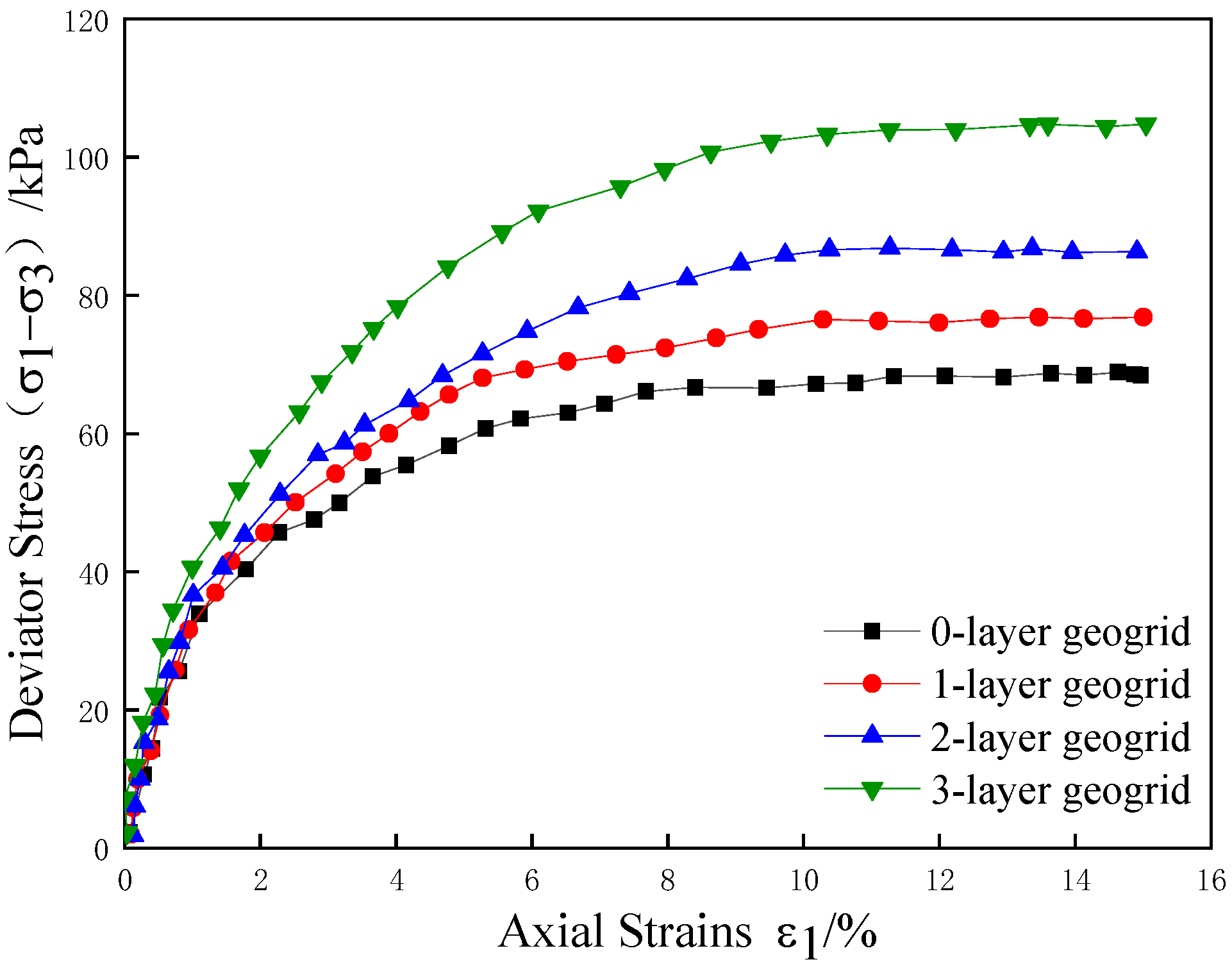
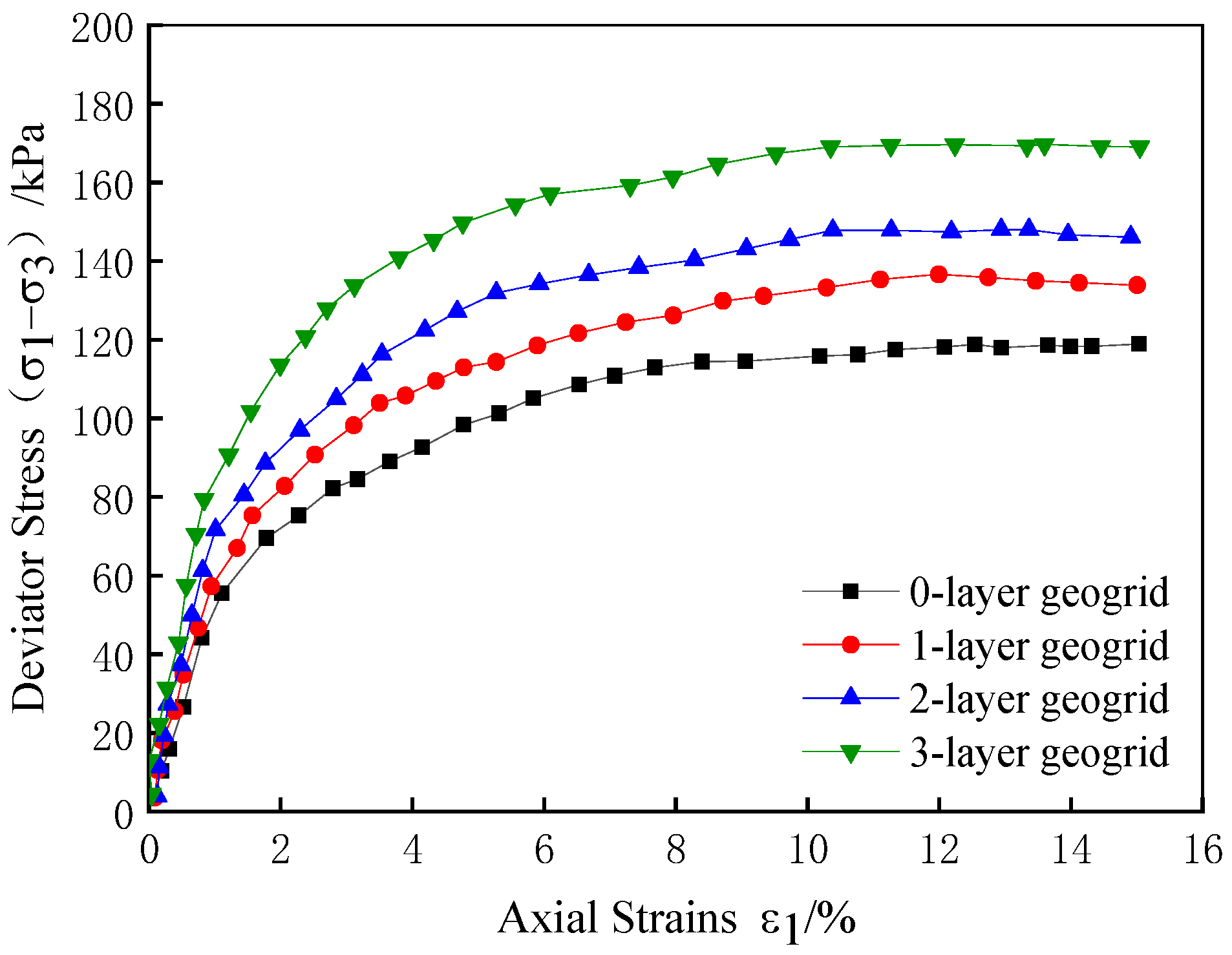
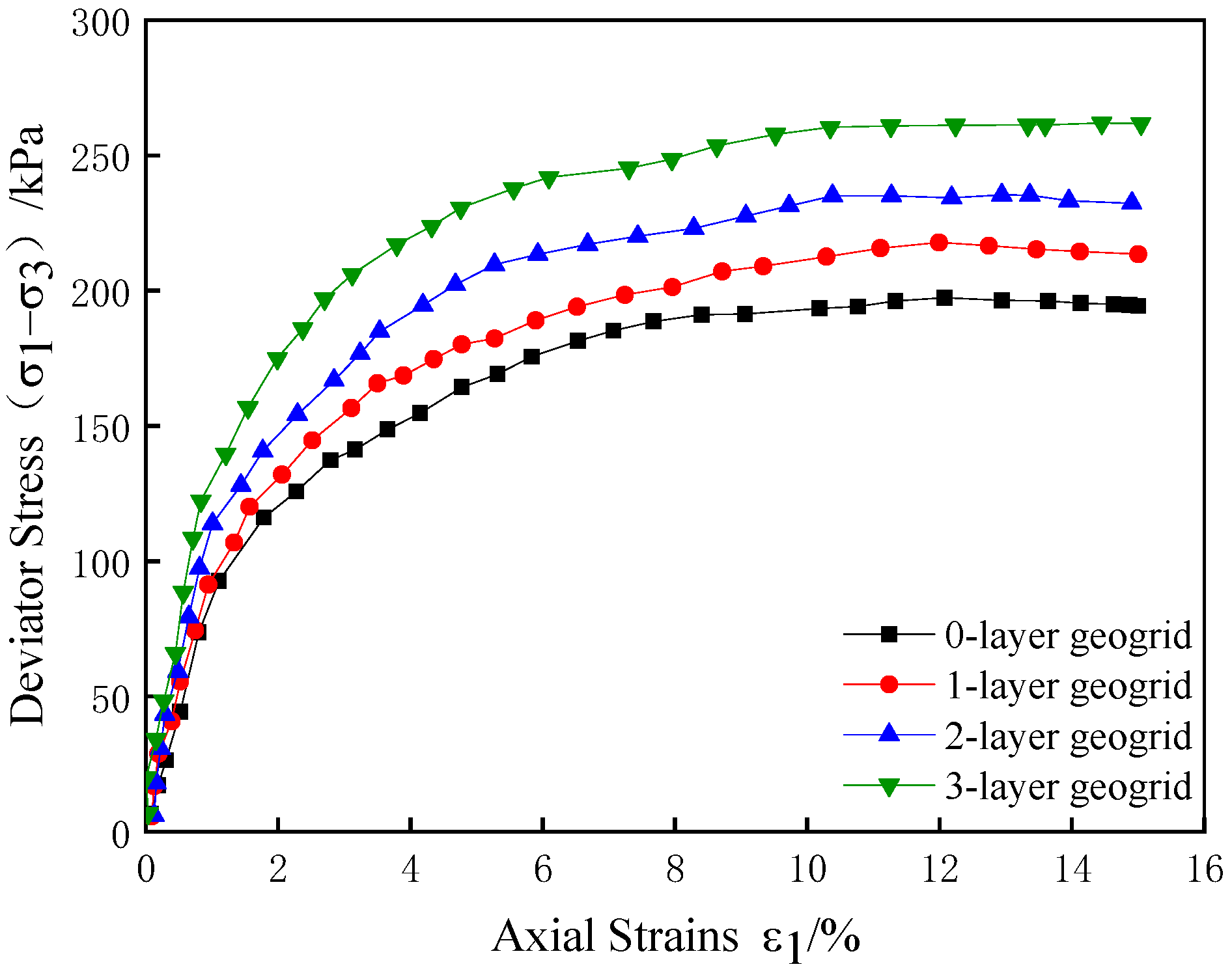
Figure 2, Figure 3 and Figure 4 illustrate the stress–strain relationships for plain soil and various reinforced soils under confining pressures of 50 kPa, 100 kPa, and 200 kPa. Initially, the stress–strain curves of different reinforced layers remain unchanged, indicating that the geogrid does not significantly affect the soil in the early stages of shear. However, as the axial strain increases, the difference in principal stresses between the reinforced and plain soils becomes more pronounced, with peak strength escalating as the number of reinforced layers increases. In specimens with a single layer of reinforcement, the increase in peak strength is modest due to the limited constraints provided by the embedded locking of the geogrid. In specimens with two or three layers of reinforcement, a synergistic effect emerges. The geogrids utilize their tensile properties more effectively, requiring soil particles to overcome the frictional resistance at the interface between the tendons and the soil. This interaction compacts the soil particles in the triaxial specimens, enhancing the density and, consequently, the peak strength and stability of the soil.
According to the theory of equivalent perimeter pressure, the influence of geogrids in reinforced soil can be interpreted as applying an equivalent perimeter pressure, Δσ3, to the soil mass. Increasing the number of reinforcement layers in a specimen is akin to elevating this equivalent perimeter pressure, which enhances soil strength by augmenting soil cohesion.
σ 1 f = ( σ 3 + Δ σ 3 ) tan ( 45 ° + φ / 2 )
Δ σ 3 = T S / Δ H
In Equations (1) and (2), σ 1 f characterizes large principal stresses in the damage of reinforced soils, σ 3 characterizes the confining pressure, Δ σ 3 characterizes the equivalent confining pressure, φ characterizes the angle of friction within the soil, T S characterizes the tensile force per unit width of reinforced material when the reinforced soil breaks down, and Δ H characterizes the distance of the reinforcing layer.
The increase in the number of reinforcement layers decreases the reinforcement spacing and increases the equivalent perimeter pressure of the reinforced soil, explaining the more significant increase in peak strength with three layers of reinforcement than with one layer of reinforcement.

2.3. Reinforcement Effect and Shear Strength Index

To assess the impact of the number of reinforcement layers more effectively on soil strength, the strength reinforcement effect coefficient, R, is introduced, as shown in Equation (3):
R = ( σ 1 σ 3 ) f R / ( σ 1 σ 3 ) f
In this equation, ( σ 1 σ 3 ) f and ( σ 1 σ 3 ) f represent the peak strengths of the plain and reinforced soils, respectively. The coefficient R, defined as the ratio of the peak strength of the reinforced soil to that of the plain soil, indicates the effectiveness of the reinforcement. An R value greater than 1 signifies a reinforcing effect, with larger values indicating more significant enhancements in soil strength.
Data from Table 3 show that R exceeds 1 under various confining pressures, confirming enhanced soil strength after clay reinforcement. The impact of a single reinforcement layer on R is minimal, showing limited strength improvement. However, with the addition of second and third layers, R significantly increases, suggesting that additional layers amplify frictional resistance and interface constraints between the soil and the reinforcement, thereby enhancing the reinforcement effect. Furthermore, when the number of reinforcement layers remains constant, R decreases as confining pressures increases, indicating that clay soil reinforcement is more effective at lower perimeter pressures in enhancing soil strength.
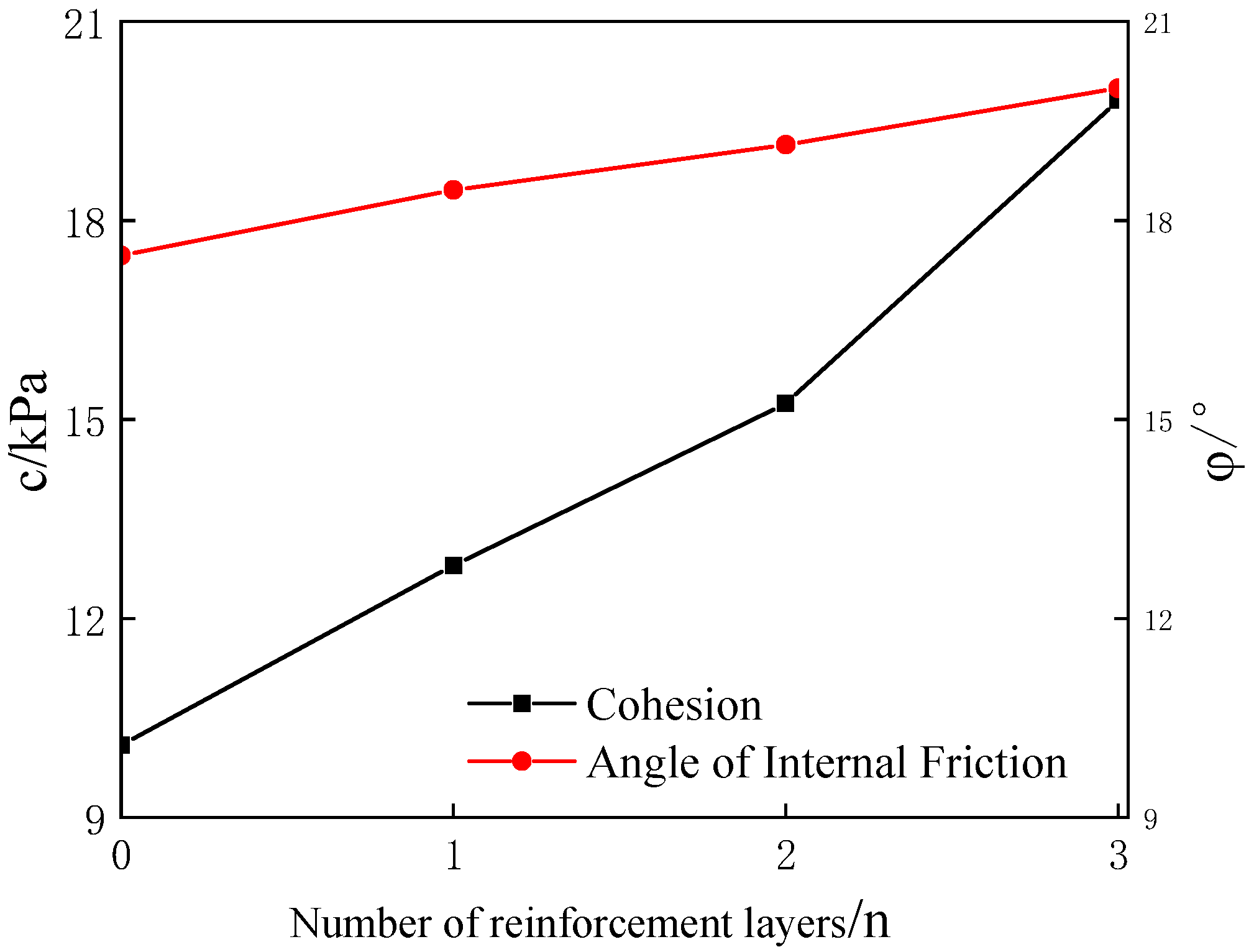
Indoor triaxial tests conducted under confining pressures of 50 kPa, 100 kPa, and 200 kPa identified peak strength values of soils with varying reinforcement layers, serving as critical indicators of soil stress at damage. These tests, guided by the Coulomb criterion and the tangent formula of Moore’s stress circle, facilitated the calculation of the cohesion c and internal friction angle of the soils φ . Notably, for soil reinforced with three layers of geogrid, cohesion c was established at 19.81 kPa, tan φ = 0.36, φ = 19.99°, as depicted in Figure 5.
Figure 6 elucidates the relationship between the number of reinforcement layers and variations in c and φ . The analysis indicates a positive correlation between soil cohesion and reinforcement layers, with a pronounced increase in cohesion observed at three layers, signifying substantial reinforcement efficacy. Conversely, the internal friction angle exhibited minimal changes across different reinforcement scenarios, highlighting that increased cohesion is the primary factor enhancing the strength of geogrid-reinforced soil.

2.4. Reinforced Soil Principal Model

Figure 2, Figure 3 and Figure 4 indicate that the stress–strain relationships of each reinforced soil sample demonstrate a hardening trend. The Duncan–Chang model is applied to analyze the triaxial test curves, facilitating the extraction of model parameters for the reinforced soil. This model is defined by the following parameters: (σ1 − σ3), representing the principal stress difference; ε1, characterizing axial strain; Ei, denoting the initial deformation modulus; and σ3, representing confining pressure, where Pa equals 101.4 kPa. The parameters a, b, K, and n are derived from empirical testing.
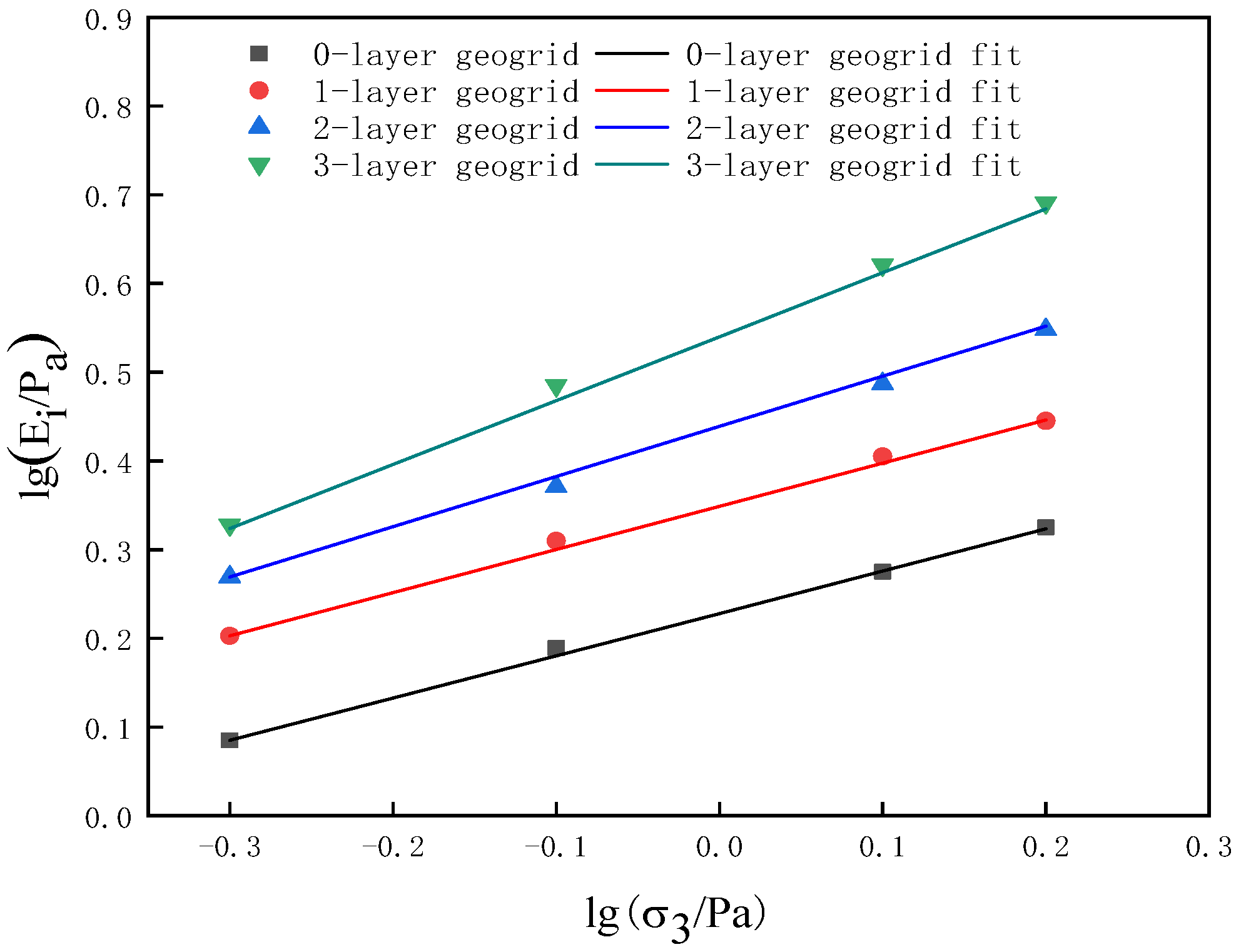
Equation (4) allows the transformation of the relationship from the (σ1 − σ3)~ε1 curve to a linear ε1/(σ1 − σ3)~ε1 relationship. Linear regression is performed on the ε1/(σ1 − σ3)~ε1 data, as shown in Figure 7, where a and b represent the intercept and slope of the fitted line, respectively. Ei is calculated as 1/a, and Rf as b(σ1 − σ3)f, with Rf denoting the failure ratio. The failure strength of the soil, (σ1 − σ3)f, is used to compute the R f and Ei values for each reinforced soil sample. Further analysis using Equation (5) yields the lg(Ei/Pa)~lg(σ3/Pa) relationship, which is also subjected to linear regression, as depicted in Figure 8. The intercept and slope of the line are denoted as lgK and n, respectively, allowing for the derivation of K and n values. The final results are presented in Table 4.
ε 1 σ 1 σ 3 = a + b ε 1
lg E i P a = lg K + n lg σ 3 P a
As depicted in Table 4, the damage ratio R f for reinforced soil increases with the addition of reinforcement layers, exhibiting values between 0.942 and 0.965. This trend suggests that the damage strength of the reinforced soil approaches the ultimate principal stress difference. The parameters K and n, related to the initial deformation modulus, vary with the number of reinforcement layers, demonstrating a sequence from the triaxial test results: three-layer reinforcement exhibits the highest initial deformation modulus, followed by two-layer, one-layer, and plain soil.
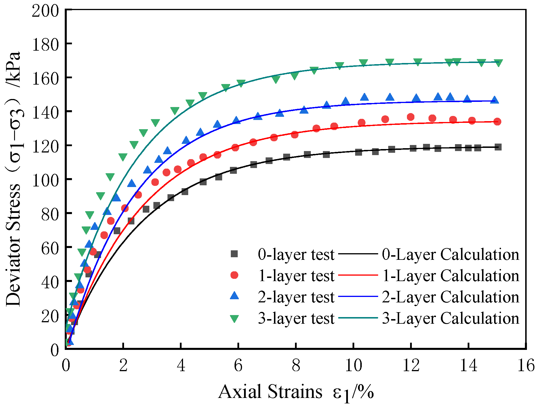
To assess the accuracy of the Duncan–Chang model parameters in representing the mechanical properties of the reinforced soil, these parameters were utilized in Equation (6) to calculate stress values at a specified strain. These values were then compared to actual test measurements.
σ 1 σ 3 = ε 1 1 K P a ( σ 3 / P a ) n + ε 1 R f σ 1 σ 3 f
Figure 9 presents the comparison between the model-calculated values and the test results at a confining pressure of 100 kPa. The alignment between the model calculations and the empirical data underscores the Duncan–Chang model’s effectiveness in capturing the intrinsic relationships of reinforced soils with geogrids. This successful validation provides a theoretical foundation for the design and analysis of reinforced soil structures.

3. Discrete Element Numerical Simulation

The discrete element method models soil particles as distinct entities and simulates their interactions using an intrinsic contact model. This approach iteratively applies Newton’s second law and the force–displacement law to update the motion behavior of particles and the contact forces between them. Utilizing the results from indoor triaxial tests, PFC3D6.0 software was employed to develop a particle flow numerical model for geogrid-reinforced clay. This model effectively addresses the limitations of traditional measurement techniques used in triaxial tests and enables a detailed examination of micro-parameters such as porosity and coordination number. Additionally, it explores the displacement vectors and contact stresses between particles at a microscopic level. Such detailed analysis aids in understanding the mechanical behavior and strength development mechanisms of geogrid-reinforced clay, offering a novel approach to studying the properties of reinforced soil structures.

3.1. Model

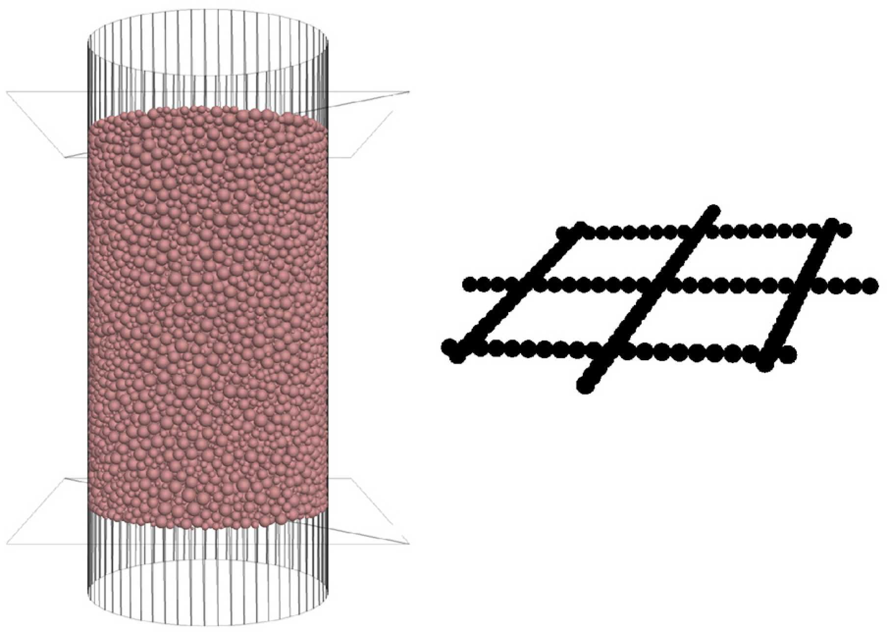
Selecting an appropriate particle contact model is essential for the accurate numerical simulation of particle flow. In this context, the parallel bond model was chosen to simulate interactions between clay particles and to model the tensile properties of geogrids. This model encompasses two types of contact interfaces: the first is a linear elastic interface without tension, capable of enduring friction, and characterized by indefinite contact duration, resembling a linear model; the second type of interface creates a parallel bond that provides tensile strength and additional shear resistance between particles. Should the stress exceed the normal tensile strength or tangential shear strength of the parallel bond, it fails and reverts to the linear model. The primary mechanical properties of the parallel bond model are depicted in Figure 10. This dual-interface approach facilitates a nuanced understanding of particle interactions under varied stress conditions, significantly enhancing the simulation’s accuracy and reliability.
The boundary of the numerical specimen model consists of a cylindrical wall and upper and lower loading plates to prevent the particles from exceeding the boundary during the loading process by enlarging the cylindrical height by 1.2 times. In the numerical simulation test, in order to simulate the loading conditions of the indoor triaxial test, the upper and lower loading plates are given a certain speed to achieve axial loading, and the radial movement of the cylindrical wall is controlled by the servo mechanism to achieve constant circumferential pressure. Due to the small particle size of the actual soil particles, considering the limited computing power of the computer, if the particles are generated according to the actual test conditions, the number of particles is too large, which will lead to a doubling of the computing time. Consequently, the clay particle size was set within a range of 0.4 to 1.8 mm, resulting in a final count of approximately 26,000 particles for the simulation. To replicate the geogrid reinforcement observed in indoor triaxial tests, soil particles at the height of the geogrid were grouped, and a corresponding grating model was created at this height with specific bonding parameters for computational purposes. Additionally, to accommodate adjustments in the number of reinforcement layers, these grouped particles could be redefined as standard soil particles. This configuration ensures the accurate simulation of geogrid reinforcement dynamics within the prescribed testing framework.

3.2. Fine View Parameter Calibration

During the calibration process in numerical simulations, not only do parameters affect the outcomes, but there is also mutual influence among them [45]. A method to appropriately reduce and control the number of parameters involves setting the stiffness ratio of soil particles and the parallel bond stiffness ratio to 1.5, and the parallel bond radius multiplier to 1.0. The friction coefficient, linear contact effective modulus, parallel bond effective modulus, bond tensile strength, and bond cohesion are calibrated. Continuous adjustment of these parameters results in a set that aligns the macroscopic mechanical properties of the numerical tests with those of laboratory triaxial tests.
For the discrete element simulation of geogrids, which primarily focuses on tensile strength, conventional tensile tests are used to calibrate the geogrid model for tensile strength, bond cohesion, linear contact effective modulus, and parallel bond effective modulus. The results of the numerical tensile tests generally meet the tensile characteristics of the geogrids, achieving an ultimate tensile strength of 50 kN/m. The friction coefficient of geogrid particles is determined by adjusting the stress–strain curve to match that of the indoor tests. The micro-parameters of clay and geogrid particles are listed in Table 5.
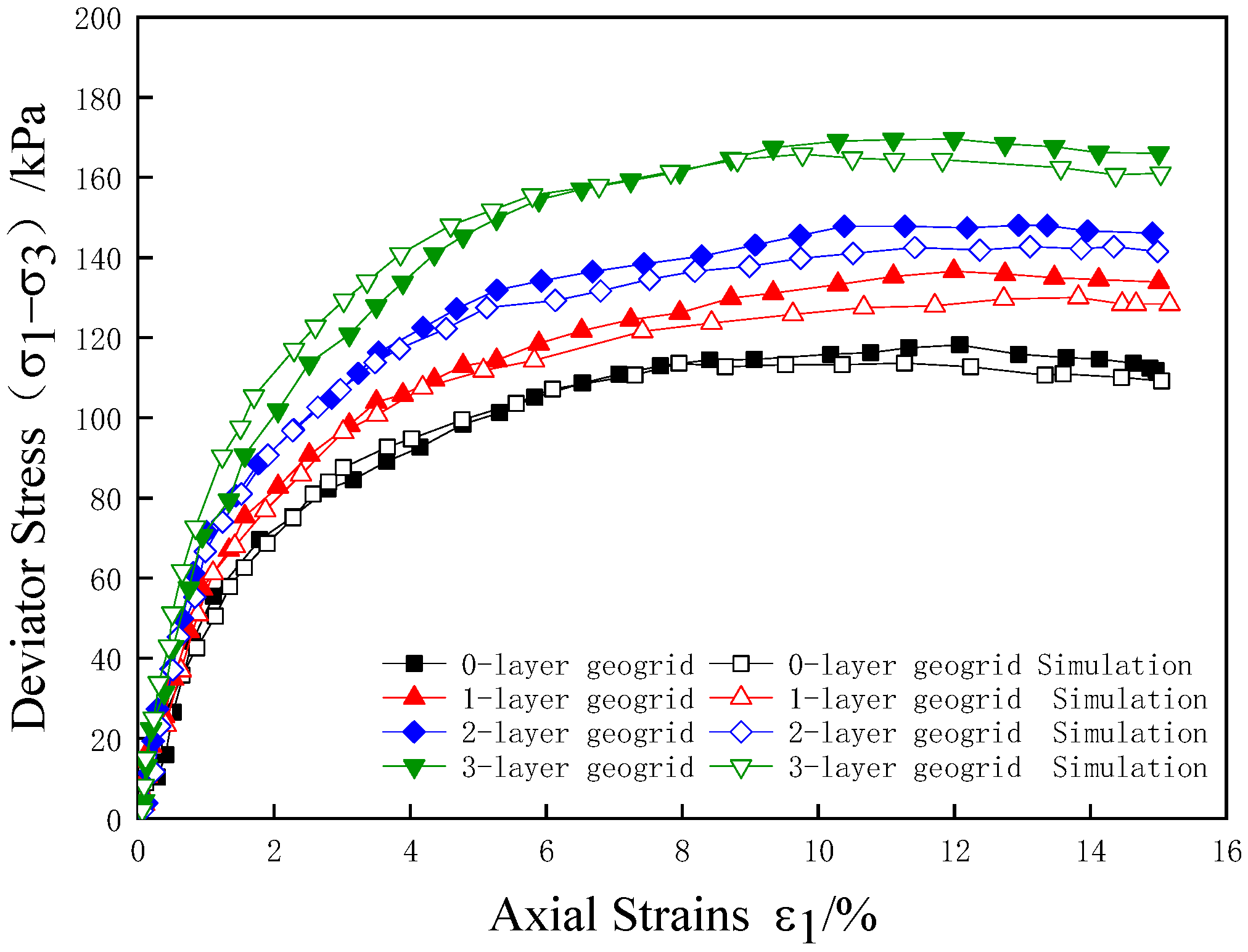
To validate the reliability of the numerical simulation, comparison curves from both the numerical test and the indoor triaxial test for plain soil and reinforced clay under a confining pressure of 100 kPa are presented in Figure 11. These curves demonstrate a close correspondence in stress–strain behavior between the granular discrete element numerical simulation and the indoor triaxial test, exhibiting similar trends in curve progression and peak intensities. This alignment indicates that the discrete element numerical model parameters are appropriately chosen, effectively mirroring the macroscopic mechanical properties observed in the triaxial tests of geogrid-reinforced clay. Such congruence underscores the model’s capability to accurately reflect the complex mechanical behaviors of reinforced soils under specified testing conditions.

3.3. Effect of Reinforcement on Porosity and Contact Number

The traditional indoor test, due to its limited measurement capabilities, only provides macroscopic mechanical responses of reinforced soil and does not allow observation of the nuanced changes in soil parameters under reinforcement conditions. In contrast, numerical testing of granular flow enables precise observation of these fine parameters during the triaxial shear process of the specimen. This capability facilitates a detailed investigation into the intricate mechanical mechanisms of clay reinforcement, offering deeper insights that go beyond the surface-level data typically garnered from conventional testing methods.
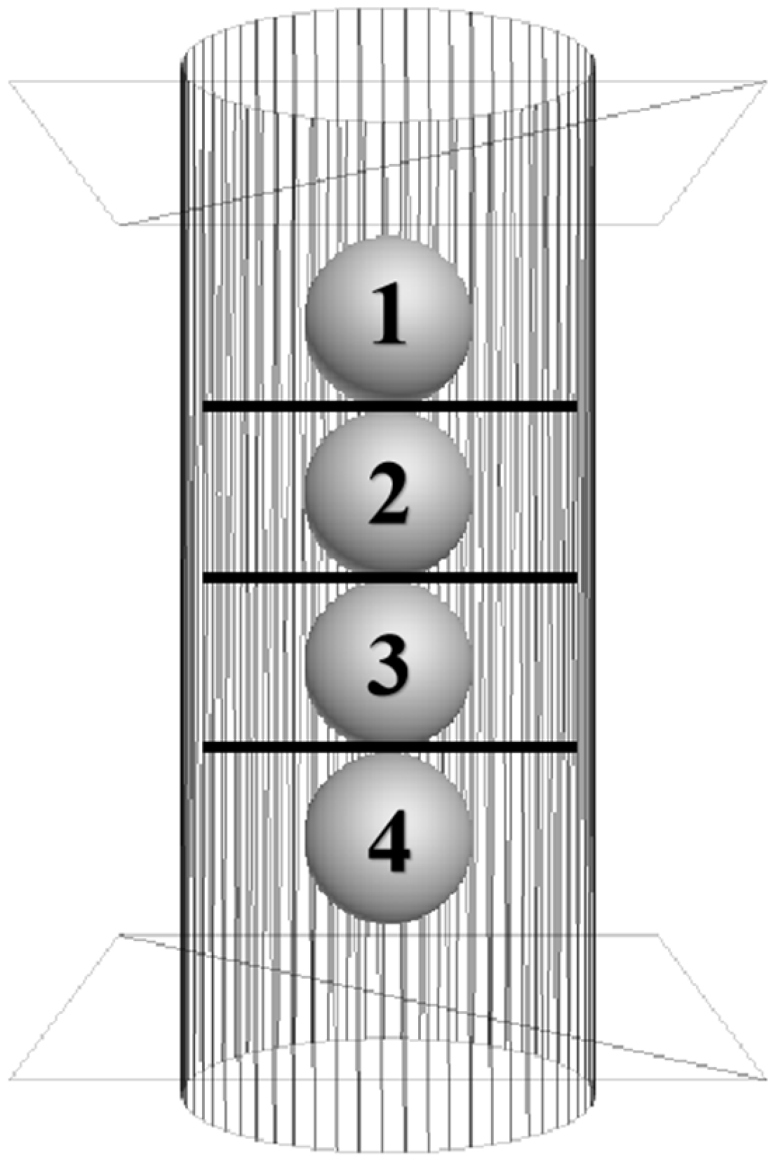
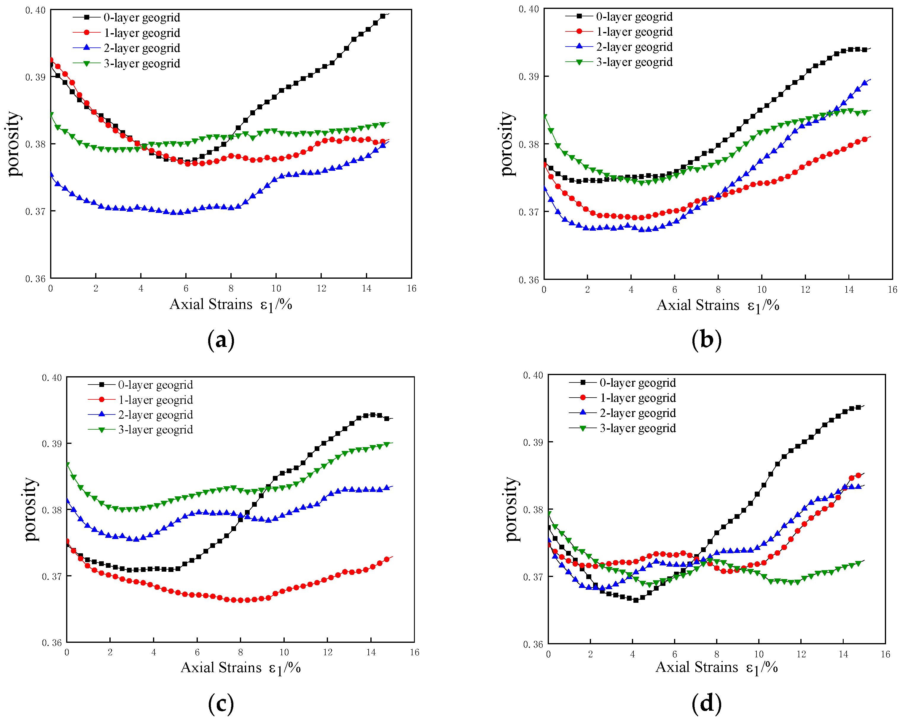
In the triaxial test, shear forces cause soil particles to slip, altering local porosity and particle contact within the specimen. The coordination number, a key metric in particle flow numerical simulations, is used to analyze changes in particle contacts. This metric assists in exploring the interaction mechanisms between the reinforcement and clay by examining variations in specimen porosity and coordination number. To monitor these changes post-reinforcement, four measuring spheres, each 24 mm in diameter and numbered from 1 to 4 from top to bottom, were positioned adjacent to each layer of the grid, taking a three-layer reinforcement setup as an example, as illustrated in Figure 12. Local porosity is defined as the ratio of the pore volume within these spheres to their total volume. Figure 13 depicts the variation curves of local porosity against axial strain at different specimen regions under a circumferential pressure of 100 kPa.
As can be seen from Figure 13, the local porosity trend of the plain soil specimen shows the phenomenon of decreasing and then increasing, because the soil body is subjected to a certain degree of compression in the initial stage of shear, the number of particles in the measuring sphere increases, and the local porosity decreases; with the increase in axial strain, the specimen gradually forms a shear zone and accompanied by shear expansion phenomenon, the two ends of the soil particles with the shear zone displacement and the middle of the soil particles produce a radial displacement of the soil particles. The number of particles in the measuring sphere decreases, and the local porosity increases. Compared with measuring balls 2 and 3, the porosity fluctuations of the plain soil samples in measuring balls 1 and 4 are larger, and the curves show a “V” shape, indicating that the particles at the upper and lower ends of the specimen are displaced more in the triaxial shear test. With the increase in the number of reinforced layers, the change trend of the porosity curves of all the measuring balls gradually flattened, and the porosity fluctuation was the smallest in the three-layer reinforcement, which reflected the restraining effect of the reinforcement on the displacement of soil particles, and the greater the number of layers of reinforcement, the more obvious the effect.
The contact number, a vital metric in particle flow simulations, assesses the contact quality and compactness within a particle system. It is defined as the ratio of the total number of contacts to the total number of particles within the measurement sphere, as expressed in Equation (7):
C n = 2 N C N b
In Equation (4), C n characterizes the contact number and N C and N b characterize the total number of contacts and the total number of particles of the soil in the measuring sphere, respectively.
This measurement enables an analysis of the extent of displacement and rotation of soil particles at the reinforced–soil interface during the triaxial shear process. Figure 14 depicts the variation curves of the contact number for soil particles across different regions under a confining pressure of 100 kPa. This visualization aids in understanding the structural dynamics and stability of the soil under stress, providing insights into the mechanical interactions at the microscopic level.
As observed in Figure 14, the curve of the contact number during the loading process exhibits fluctuations, indicating continuous changes in the contact number between soil particles and the occurrence of relative misalignment and slippage during the shear process. The contact numbers of measuring balls 1–4 demonstrate an initial increase followed by a decrease. This pattern can be attributed to the axial loading, which compresses the specimen, thereby increasing the contact between soil particles. As the specimen forms a shear zone, displacement occurs at the ends of the soil particles within this zone. In the later stages of loading, a shear expansion phenomenon leads to radial displacements in the center of the soil particles, causing fluctuations in the contact numbers and a subsequent decrease in the coordination number. This decrease is correlated with the increase in particle displacement, further reducing particle contacts and coordination numbers.
The contact number for reinforced soil exceeds that of plain soil, illustrating an increase in inter-particle contacts post-reinforcement, enhanced compactness, and improved structural strength. Notably, in specimens with three-layer reinforcement, the contact numbers in measuring spheres 2 and 3 demonstrate significant increases, indicating more effective constraint of soil particles in the specimen’s midsection by the geogrid. Conversely, the particle contacts in spheres 1 and 4 are less affected by the reinforcement, showing only minor increases in coordination numbers. This limited effect is attributed to the considerable displacement of soil particles at the specimen’s ends, where the reinforcement’s ability to constrain particle displacement diminishes, leading to reduced inter-particle contact as displacement intensifies.
The observed changes in porosity and contact number in the reinforced specimens illustrate the reinforcement’s restraining and locking effects on soil particles. These variations not only elucidate the dynamic displacement behaviors of soil particles during the triaxial shear process but also hold significant implications for advancing the understanding of reinforced soil’s mechanical behavior and enhancing reinforcement design. This comprehensive analysis is crucial for optimizing reinforcement strategies and achieving the desired soil stabilization outcomes.

3.4. Change in Contact Force

In the triaxial test, the variation in contact force among soil particles reflects the force mechanism acting within the soil during the shearing process. Investigating this variation enables a thorough examination of the mechanical behavior and damage mechanisms of the soil. Figure 15 illustrates the distribution of contact forces in triaxial specimens with varying numbers of reinforcement layers under a confining pressure of 100 kPa at an axial strain ε1 of 15%. This comparison aids in analyzing how different reinforcement layers influence the internal contact forces within the specimen. This analysis is crucial for understanding the structural interactions and the impact of reinforcement on soil stability under stress.
Figure 15 illustrates the distribution of particle contact forces within specimens at varying reinforcement layers, with the depth of color and thickness of lines in the figure representing the magnitude of the contact forces between particles. In the plain soil specimen, the distribution of contact forces is relatively uniform, but the forces themselves are minimal, indicating low strength in the plain soil specimen. Following the introduction of a single reinforcement layer, there was a marked increase in the large contact force chains, depicted by the yellow and red lines, after soil reinforcement. This change indicates a significant enhancement in the contact forces between soil particles. The lines depicting the contact force chains between the reinforcement and soil particles are red, signifying that the contact forces at the reinforcement-soil interface are substantial. This increased force at the interface indicates that the reinforcement restricts and disperses stress among the soil particles, which macroscopically manifests as enhanced strength in the reinforced specimen.
As the number of reinforcement layers increases, the larger contact force chains predominantly concentrate near the interfaces between the reinforcement and soil and along the axial region of the specimen, and the contact force on both sides of the middle of the specimen is small. This effect is most pronounced in specimens with three-layer reinforcement due to the decreased grid spacing and the enhanced synergistic effect between the grids, which augment the frictional resistance and embedded lock of the particles, thereby increasing the contact forces near the reinforcement interfaces. There is also some constraint on the lateral deformation of the specimen. The concentration of large contact force chains in the axial region of the specimen suggests that the particles in this area, along with the reinforcement, bear most of the axial load. The enhancement not only increased the bearing capacity but also the stability of the soil body. These results deepen our understanding of the stress transfer mechanism, particle friction and interlock, and the macroscopic mechanical response of the soil during shearing. Furthermore, these findings offer valuable insights into the mechanical behavior of reinforced soil structures.
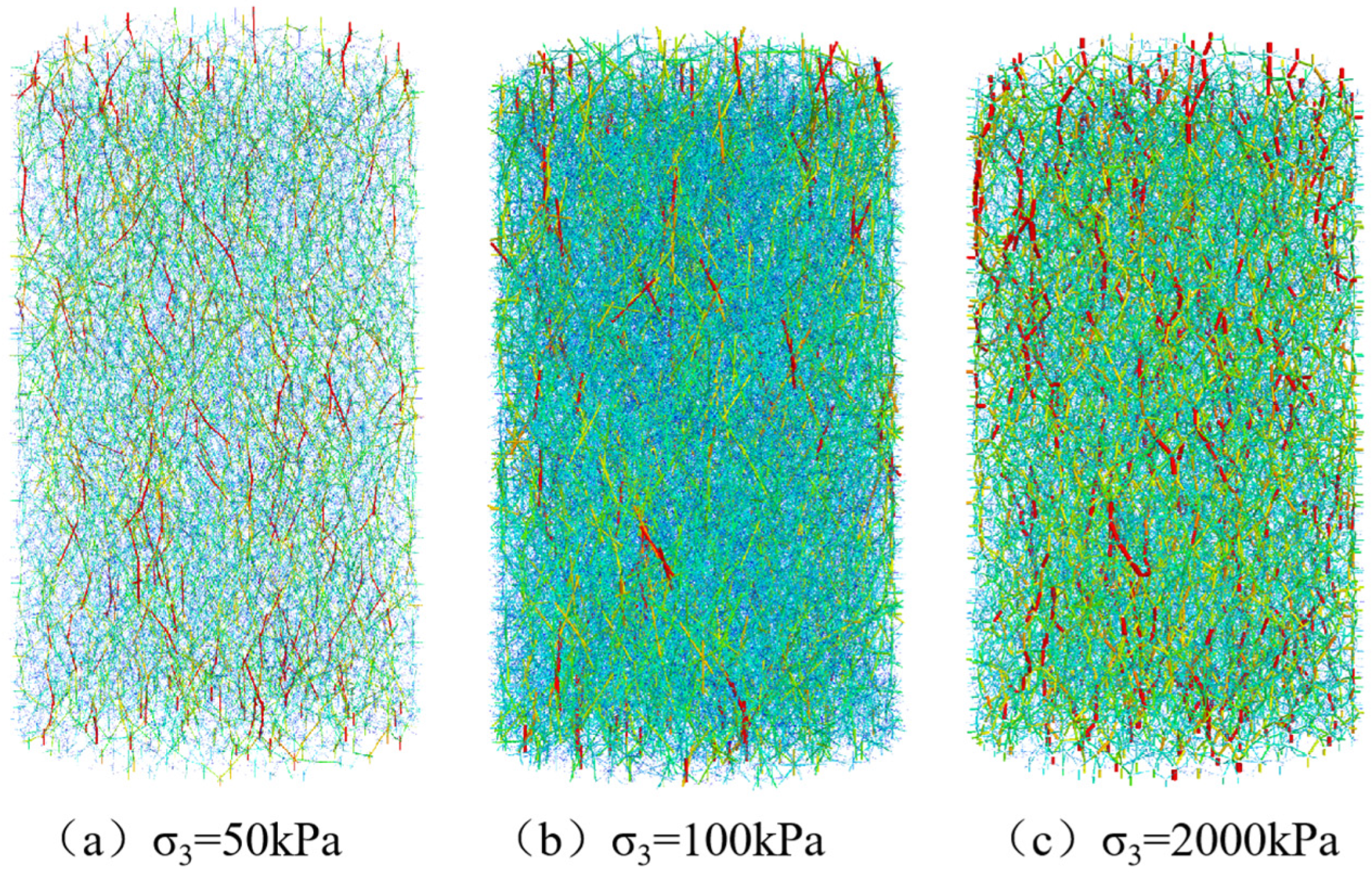
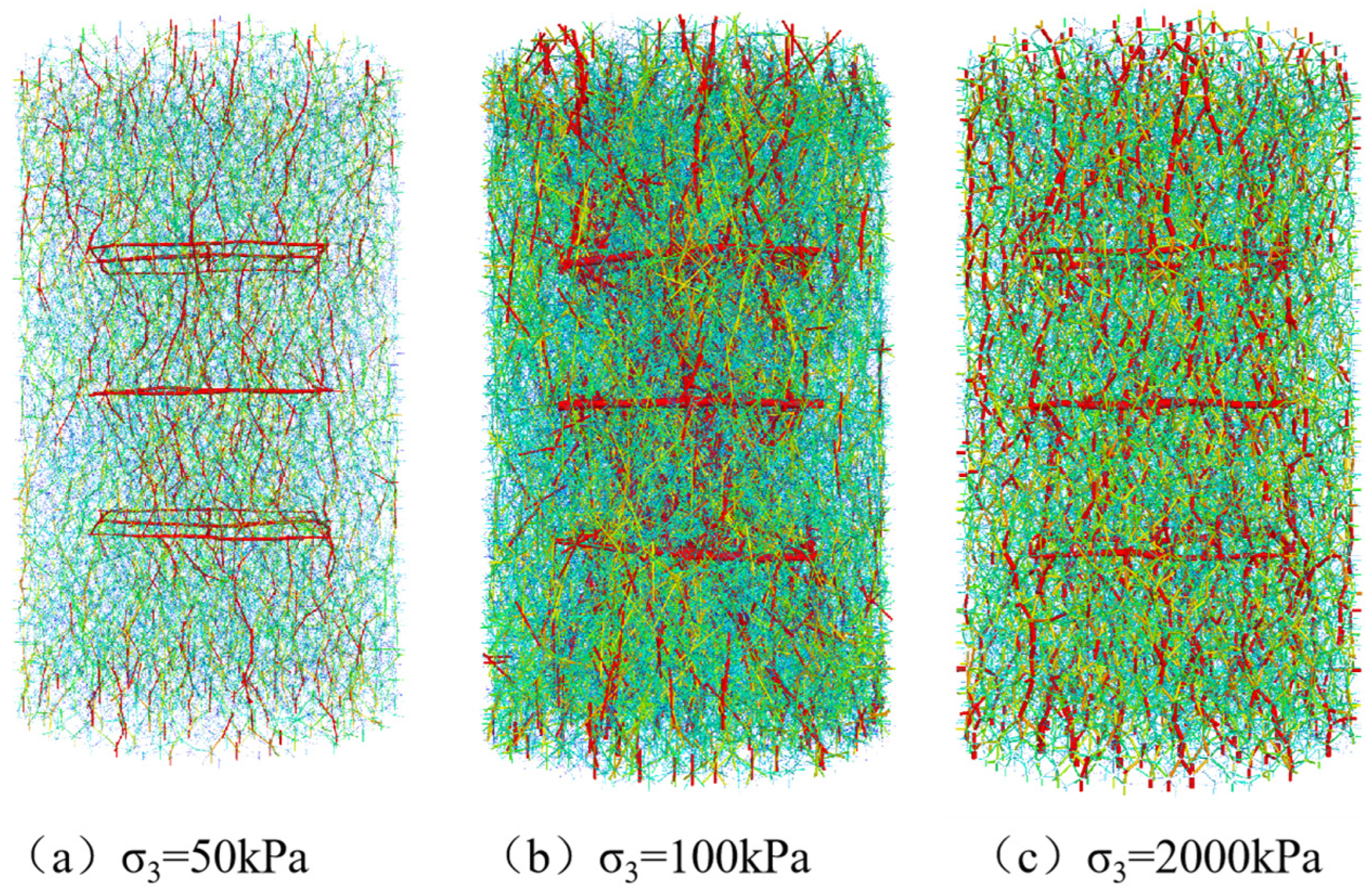
Figure 16 and Figure 17 illustrate that the contact force within both plain and three-layer reinforced soil increases with rising perimeter pressure. At 50 kPa, the contact force is minimal, as indicated by the lightest hues in the contact force chain, corresponding to the lowest peak strength of the soil body. At perimeter pressures of 100 and 200 kPa, the contact force chain densifies, signifying enhanced particle interactions and thicker lines, indicative of increased contact stress and substantially greater peak soil strength.
A comparison of the contact force chain distribution across different pressures reveals that at 50 kPa and 100 kPa, significant contact stress is predominantly located in the middle of the three-layer reinforced specimen, where the reinforcement effectively embeds and locks the particles. This dense distribution near the reinforcement layers signifies an optimal reinforcing effect at these pressures. However, at 200 kPa, while the contact force chain between the specimen and the reinforcement is uniformly distributed, the reinforcement effect appears less significant. This uniformity indicates denser particle interactions, which, while increasing the bond between soil particles, also suggests a decrease in the reinforcing effectiveness at high perimeter pressures. These observations align with the outcomes from previous indoor tests, highlighting that the reinforcing effectiveness of geogrids diminishes under high perimeter pressures.

4. Conclusions

The effects of varying the number of reinforced layers on the macroscopic mechanical properties of geogrid-reinforced clay were examined through indoor triaxial testing. The Duncan–Chang model facilitated the fitting of the test data. Subsequent discrete element numerical analyses using PFC3D6.0 software elucidated the impact of reinforcement on the microstructural characteristics of the clay, including porosity, coordination number, and contact stress. The following conclusions were drawn:
(1)
The results of the indoor triaxial test show that the peak strength and cohesion c of the stress–strain curve of the specimen after reinforcement increase with the increase in the number of layers of reinforcement, and the enhancement of the angle of internal friction is not obvious. The three layers of reinforcement play a synergistic role between the grids, and the peak strength increases significantly. Analysis of the reinforcing effect coefficient found that, when the number of reinforced layers is the same, the effect of clay reinforcement at low perimeter pressure is better.
(2)
The analysis of triaxial test curves for reinforced soil revealed that the stress–strain relationship adheres to the Duncan–Chang model. Subsequent extraction of Duncan–Chang model parameters from the reinforced soil confirmed their validity. These parameters were then rigorously evaluated by comparing the model’s calculated values with experimental data, verifying the accuracy of the model parameters. This comparison underscores the reliability of the Duncan–Chang model in predicting the behavior of reinforced soils under stress conditions.
(3)
The results from discrete element numerical tests indicate that reinforcing a specimen significantly reduces soil porosity fluctuations. Notably, the porosity at both ends of the specimen is substantially influenced by the reinforcement. This suggests that the frictional resistance at the reinforcement-soil interface effectively inhibits soil particle displacement during shear processes. Furthermore, as the number of reinforcing layers increases, so does the inhibitory effect. In the central region of the specimen, there is a notable increase in soil particle count. The reinforcement constraints embedded within the material lead to increased inter-particle contact, thereby enhancing the compactness of the soil. This increase in particle contact directly contributes to improved soil structure and stability.
(4)
Analyzing the contact force distribution law of the reinforced soil particles demonstrated that the contact force at the reinforcement and the axial region of the specimen after reinforcement increased significantly, and the reinforcement played the role of restraining the soil particles and spreading the stress reinforcement, reflecting the characteristics of the stress transfer and distribution in the reinforced soil.

Author Contributions

Conceptualization, X.W. and Q.H.; methodology, X.W.; writing—original draft, X.W.; resources, G.T.; review and editing, G.T.; funding acquisition, Y.L.; visualization, Y.L. All authors have read and agreed to the published version of the manuscript.

Funding

Foundation of China: 52078195; General Program of National Natural Science Foundation of China: U22A20232.

Data Availability Statement

Data will be made available upon request.

Conflicts of Interest

The authors declare that there are no conflicts of interest.

References

  1. Wang, J.-Q.; Xu, L.-J.; Huang, S.-B.; Liu, Z.-Q. Bearing capacity analysis of geogrid reinforced abutment retaining wall under dynamic load. Rock Soil Mech. 2019, 40, 4220–4228+4269. [Google Scholar]
  2. Jawad, Z.H.; Shakir, R.R. Behavior of foundation rested on geogrid-reinforced soil: A review. IOP Conf. Ser. Mater. Sci. Eng. 2021, 1094, 012110. [Google Scholar] [CrossRef]
  3. Yang, G.-Q.; Zhou, Y.-T.; Zhou, Q.-Y.; Xue, X.-H. Experimental research on geogrid reinforced earth retaining wall. Rock Soil Mech. 2009, 30, 206–210. [Google Scholar]
  4. Luo, T.; Chen, P.; Qiu, H.; Fu, S.; Sun, C. A Review On The Interaction between Geogrid and backfill. Eng. J. Wuhan Univ. 2020, 53, 111–115. [Google Scholar]
  5. Xiao, C.-Z.; Liu, B.; Li, Y.-R.; Sun, J.-C. Test study of long-term performances of reinforced cohesion soil retaining wall. Rock. Soil. Mech. 2012, 33, 109–114. [Google Scholar]
  6. Wu, H.; Gao, J.; Liu, C.; Guo, Z.; Luo, X. Reusing waste clay brick powder for low-carbon cement concrete and alkali-activated concrete: A critical review. J. Clean. Prod. 2024, 449, 141755. [Google Scholar] [CrossRef]
  7. Cai, J.-T. Pull-out test on interface behavior between expansive soils and geogrids. Rock Soil Mech. 2015, 36, 204–208. [Google Scholar]
  8. Abdic, M.R.; Zandieh, A.R.; Mirzaeifar, H.; Arjomand, M.A. Influence of geogrid type and coarse grain size on pull out behaviour of clays reinforced with geogrids embedded in thin granular layers. Eur. J. Environ. Civ. Eng. 2021, 25, 2161–2180. [Google Scholar] [CrossRef]
  9. Sakleshpura, V.A.; Prezzia, M.; Salgadoa, R.; Siddikib, N.Z.; Choic, Y.S. Large-scale direct shear testing of geogrid-reinforced aggregate base over weak subgrade. Int. J. Pavement Eng. 2019, 20, 649–658. [Google Scholar] [CrossRef]
  10. Wang, J.-Q.; Zhou, Y.-F.; Tang, X.-Y.; Huang, S.-B. Development and application of large size direct shear test apparatus with visual and digital collection functions for reinforced soil. Rock Soil Mech. 2017, 38, 1533–1540. [Google Scholar]
  11. Akbarimehr, D.; Fakharian, K. Dynamic shear modulus and damping ratio of clay mixed with waste rubber using cyclic triaxial apparatus. Soil. Dyn. Earthq. Eng. 2021, 140, 106435. [Google Scholar] [CrossRef]
  12. Akbarimehr, D.; Hosseini, S.M.M.M. Elasto-plastic characteristics of the clay soil mixed with rubber waste using cyclic triaxial test results. Arab. J. Geosci. 2022, 15, 1280. [Google Scholar] [CrossRef]
  13. Yang, Z. Strength and Deformation Characteristics of Reinforced Sand; University of California: Los Angeles, CA, USA, 1972. [Google Scholar]
  14. Schlosser, F.; Long, N.T. Recent results of French research on reinforced earth. J. Constr. Div. 1974, 100, 223–237. [Google Scholar] [CrossRef]
  15. Zakarka, M.; Skuodis, Š.; Dirgėlienė, N. Triaxial Test of Coarse-Grained Soils Reinforced with One Layer of Geogrid. Appl. Sci. 2023, 13, 12480. [Google Scholar] [CrossRef]
  16. Skuodis, Š.; Dirgėlienė, N.; Medzvieckas, J. Using Triaxial Tests to Determine the Shearing Strength of Geogrid-Reinforced Sand. Stud. Geotech. Mech. 2020, 42, 341–354. [Google Scholar] [CrossRef]
  17. Chen, X.; Zhang, J.; Li, Z. Shear behaviour of a geogrid-reinforced coarse-grained soil based on large-scale triaxial tests. Geotext. Geomembr. 2014, 42, 312–328. [Google Scholar] [CrossRef]
  18. Luo, Z.-G.; Ding, X.-M.; Ou, Q.; Jiang, C.-Y.; Fang, H.-Q. Experimental study on strength and deformation characteristics of coral sand reinforced by geogrid. Rock Soil Mech. 2023, 44, 1053–1064. [Google Scholar]
  19. Cai, Y.-M.; Wang, Z.-J.; Qi, Y.-F.; Yang, G.-Q.; Wang, H. Experimental study on dynamic properties of geogrid reinforced rubber gravel. Rock Soil Mech. 2024, 45, 87–96+107. [Google Scholar]
  20. Mittal, A.; Shrivastava, A.K. Stress-strain characteristics of landfill clay cover barriers under geogrid reinforcements. Innov. Infrastruct. Solut. 2020, 5, 19. [Google Scholar] [CrossRef]
  21. Wang, Z.; Qi, Y.; Yang, G.; Cai, Y.; Liu, W. Experimental Investigations of Large-scale Triaxial Tests on Geocell Reinforced Gravel Composites. J. China Railw. Soc. 2023, 45, 161–169. [Google Scholar]
  22. Song, F.; Shi, L.; Fan, M. Stress-strain response of geocell-reinforced normally consolidated silty clay. Bull. Geol. Sci. Technol. 2024, 43, 184–193. [Google Scholar]
  23. Zhao, X.; Lu, X.; Rong, S.; Zhu, J. Experimental Study on Deformation and Strength Behavior of Geotextile Reinforced Coarse-grained Soil. Adv. Eng. Sci. 2018, 50, 165–173. [Google Scholar]
  24. Liu, F.-C.; Wu, M.-T.; Yang, J. Experimental study of strength characteristics of geogrid reinforced rubber sand mixtures. Rock Soil Mech. 2019, 40, 580–591. [Google Scholar]
  25. Yi, F.; Du, C. Triaxial Testing of Geosynthetics Reinforced Tailings with Different Reinforced Layers. Materials 2020, 13, 1943. [Google Scholar] [CrossRef] [PubMed]
  26. Wang, X.-Q.; Guo, M.; Hu, B. Triaxial testing study of expansive soil reinforced with geogrid. Rock Soil Mech. 2011, 3, 1649–1653. [Google Scholar]
  27. Xiaojun, L.; Xiaohong, B.; Xianzhi, H. Study on the constitutive relationship of geotechnical belt reinforced gravel soil by triaxial test. Rock Soil Mech. 2004, S2, 57–60. [Google Scholar]
  28. Hongwei, W.; Zehong, Y.; Huawei, Y. Study on Triaxial Test of Geosynthetics-reinforced Clay Soil. Eng. Mech. 2007, 5, 107–113. [Google Scholar]
  29. Xiong, S.; Jiasheng, Z.; Fei, M. Research on large-scale triaxial test of reinforced coarse-grained soi. Adv. Eng. Sci. 2014, 46, 52–58. [Google Scholar]
  30. He, Z.J.; Asiga; Zou, J.F. Analysis of large-scale triaxial test of reinforced sand with fine-grained soil. J. Railw. Sci. Eng. 2019, 16, 2451–2458. [Google Scholar]
  31. Zhao, Y.; Lin, X.; Gong, W.; Li, P.; Li, G.; Wang, L. Mechanical Properties of Fiber-Reinforced Soil under Triaxial Compression and Parameter Determination Based on the Duncan-Chang Model. Appl. Sci. 2020, 10, 9043. [Google Scholar] [CrossRef]
  32. Wu, M.; Wang, J.; Russell, A.; Cheng, Z. DEM modelling of mini-triaxial test based on one-to-one mapping of sand particles. Geotechnique 2021, 71, 714–727. [Google Scholar] [CrossRef]
  33. Wang, J.Q.; Zhang, L.L.; Chen, Y.J.; Shi, C.H. Mesoscopic analysis of reinforced sand triaxial test using PFC3D. J. Hydraul. Eng. 2017, 4, 426–434+445. [Google Scholar]
  34. Gonga, L.; Niea, L.; Liua, C.; Xua, Y. Modelling Triaxial Tests on Fibre-Reinforced Sands with Different Fibre Orientations Using the Discrete Element Method. Ksce J. Civ. Eng. 2020, 24, 2268–2280. [Google Scholar] [CrossRef]
  35. Stahl, M.; Konietzky, H.; Kamp, L.T.; Jas, H. Discrete element simulation of geogrid-stabilised soi. Acta Geotech. 2014, 9, 1073–1084. [Google Scholar] [CrossRef]
  36. Chen, C.; McDowell, G.R.; Thom, N.H. Discrete element modelling of cyclic loads of geogrid-reinforced ballast under confned and unconfned conditions. Geotext. Geomembr. 2012, 35, 76–86. [Google Scholar] [CrossRef]
  37. Cui, L.; Cao, W.; Sheng, Q.; Xie, M.; Yang, T.; Xiao, P. Analysis of Layered Geogrids-Sand-Clay Reinforced Structures under Triaxial Compression by Discrete Element Method. Appl. Sci. 2021, 11, 9952. [Google Scholar] [CrossRef]
  38. Wang, Z.; Jacobs, F.; Ziegler, M. Visualization of load transfer behaviour between geogrid and sand using PFC2D. Geotext. Geomembr. 2014, 42, 83–90. [Google Scholar] [CrossRef]
  39. Chen, C.; Duan, Y.-D.; Rui, R.; Wang, L. Study of single and two-layer geogrid reinforced ballasted trackbed using pull-out test and discrete element method. Rock Soil Mech. 2021, 42, 954–962+975. [Google Scholar]
  40. Tran, V.D.H.; Meguid, M.A.; Chouinard, L.E. A finiteediscrete element framework for the 3D modeling of geogride soil interaction under pullout loading conditions. Geotext. Geomembr. 2013, 37, 1–9. [Google Scholar] [CrossRef]
  41. Wang, J.; Zhou, J.; Wu, H.; Xu, H. Discrete element mesoscopic simulation of the reinforced soil pullout test interface effect. J. Harbin Eng. Univ. 2014, 35, 839–845. [Google Scholar]
  42. Ngo, N.T.; Indraratna, B.; Rujikiatkamjorn, C. DEM simulation of the behaviour of geogrid stabilised ballast fouled with coal. Comput. Geotech. 2014, 55, 224–231. [Google Scholar] [CrossRef]
  43. Gaoa, G.; Meguidb, M.A. Effect of particle shape on the response of geogrid-reinforced systems: Insights from 3D discrete element analysis. Geotext. Geomembr. 2018, 46, 685–698. [Google Scholar] [CrossRef]
  44. Chen, W.-B.; Zhou, W.-H.; Jing, X.-Y. Modeling Geogrid Pullout Behavior in Sand Using Discrete-Element Method and Effect of Tensile Stiffness. Int. J. Geomech. 2019, 19, 04019039. [Google Scholar] [CrossRef]
  45. Adajar, J.B.; Ubay, I.O.; Alfaro, M.; Chen, Y. Discrete Element Modelling of Undrained Consolidated Triaxial Test on Cohesive Soils. In Geo-Congress 317; American Society of Civil Engineers: Reston, VA, USA, 2020. [Google Scholar]
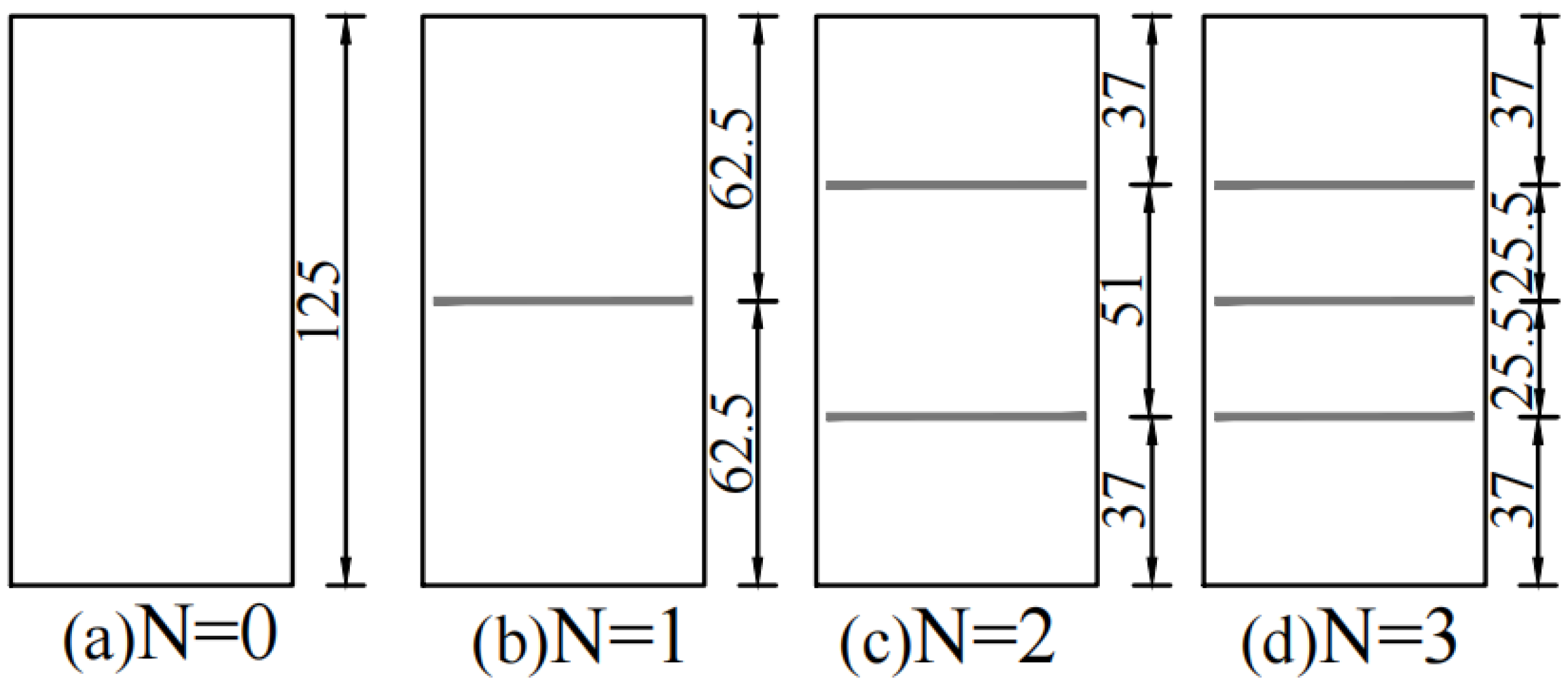
Figure 1. Schematic diagram of geogrid reinforcement.
Buildings 14 01422 g001
Figure 2. Stress–strain relationship of reinforced soil with a confining pressure of 50 kPa.
Buildings 14 01422 g002
Figure 3. Stress–strain relationship of reinforced soil with a confining pressure of 100 kPa.
Buildings 14 01422 g003
Figure 4. Stress–strain relationship of reinforced soil with a confining pressure of 200 kPa.
Buildings 14 01422 g004
Figure 5. Molar stress circle and strength envelope.
Buildings 14 01422 g005
Figure 6. Shear strength index.
Buildings 14 01422 g006
Figure 7. Linear fit of ε1/(σ1 − σ3)~ε1 for soil at 100 kPa confining pressure.
Buildings 14 01422 g007
Figure 8. Linear fit of lg(Ei/Pa)~lg(σ3/Pa) for soil at 100 kPa confining pressure.
Buildings 14 01422 g008
Figure 9. Calculated and experimental values of the model.
Buildings 14 01422 g009
Figure 10. Discrete element numerical model diagram.
Buildings 14 01422 g010
Figure 11. Comparison of stress–strain curves between discrete element numerical tests and indoor triaxial tests.
Buildings 14 01422 g011
Figure 12. Schematic diagram of measurement ball layout.
Buildings 14 01422 g012
Figure 13. Porosity variation curves in different regions of the sample with a confining pressure of 100 kPa: (a) measuring ball 1; (b) measuring ball 2; (c) measuring ball 3; and (d) measuring ball 4.
Buildings 14 01422 g013
Figure 14. Contact number variation curve in different regions of the sample with a confining pressure of 100 kPa: (a) measuring ball 1; (b) measuring ball 2; (c) measuring ball 3; and (d) measuring ball 4.
Buildings 14 01422 g014
Figure 15. Distribution of contact force under different reinforcement layers: (a) plain soil; (b) 1-layer geogrid; (c) 2-layer geogrid; and (d) 3-layer geogrid.
Buildings 14 01422 g015
Figure 16. Chain diagram of contact force for veg soil specimens with 15% strain at different confining pressure.
Buildings 14 01422 g016
Figure 17. Chain diagram of contact force for 3-layer reinforced specimens with 15% strain under different confining pressure.
Buildings 14 01422 g017
Table 1. Basic physical indicators of soil samples.
SoilMaximum Dry Density ρ/(g·cm−3)Moisture Content ω/%Liquid Limit ωL/%Plastic Limit ωp/%Plastic Limit Index Ip
clay1.681733.619.214.4
Table 2. Technical parameters of geogrids.
Reinforcing MaterialSpecificationTensile Strength
/(kN/m)
Elongation/(%)Mesh Size/mm
Woven geogridPET50-50501320.0 × 20.0
Table 3. Strength reinforcement effect coefficient R.
Number of
Reinforcement Layers
σ3 = 50 kPaσ3 = 100 kPaσ3 = 2200 kPa
11.131.161.06
21.291.251.19
31.531.421.32
Table 4. Parameters of the Duncan–Chang model for plain and reinforced soils.
Number of
Reinforcement Layers
ab R f Kn
00.00610.00720.9421.6910.477
10.00460.00620.9542.2320.486
20.00370.00550.9592.7480.566
30.00280.00450.9653.4670.721
Table 5. Microscopic parameters.
Parameter ItemsClayGeogrid
Particle radius/×10−3 m0.4~1.81.0
Particle density/Kg∙m−32650800
Coefficient of friction0.30.5
Porosity0.45
Bonding strength/kPa153.18 × 1011
Cohesion/kPa153.18 × 1011
Linear contact effective modulus/kPa4.4 × 1036.0 × 1010
Parallel bonded effective modulus/kPa332.42 × 105
Disclaimer/Publisher’s Note: The statements, opinions and data contained in all publications are solely those of the individual author(s) and contributor(s) and not of MDPI and/or the editor(s). MDPI and/or the editor(s) disclaim responsibility for any injury to people or property resulting from any ideas, methods, instructions or products referred to in the content.