Article

Simulation Test of an Intelligent Vibration System for Concrete under Reinforcing Steel Mesh

by
Hongyu Liang
1,
Zhigang Wu
2,
Jifeng Hu
2,
Yuannan Gan
2 and
Sheng Qiang
1,*
1
College of Water Conservancy and Hydropower, Hohai University, Nanjing 210098, China
2
China Anneng Group Second Engineering Bureau Co., Ltd., Nanchang 330095, China
*
Author to whom correspondence should be addressed.
Buildings 2024, 14(8), 2277; https://doi.org/10.3390/buildings14082277
Submission received: 11 June 2024 / Revised: 20 July 2024 / Accepted: 22 July 2024 / Published: 23 July 2024

Abstract

:
Concrete vibration construction sustains high labor intensity, a poor working environment, difficulties in quality control, and other problems. Current research on concrete vibration focuses on monitoring vibration quality, evaluating vibration processes quantitatively, and assessing mechanical vibration of unreinforced mesh concrete (plain concrete). Standardizing concrete vibration under reinforcing steel mesh remains difficult. There is still a lag in the evaluation of the quality of rework and the consumption of human and material resources. To tackle these issues, a vibrating robotic arm system based on automation control technology, machine vision, and kinematic modeling is proposed. Research and simulation tests on intelligent concrete vibration under reinforcing steel mesh aim to enhance construction efficiency and quality. A five-degree-of-freedom robotic arm with a vision module identifies each rebar grid center in the image, extracts the pixel coordinates, and converts them to the mechanical coordinates by the integration of machine vision algorithms. A vibrator point screening algorithm is introduced to determine actual vibrator point locations based on specific insertion spacing, alongside a vibro-module for vertical movement. Real-time assessment of vibration quality is achieved using the YOLOv5 target detection model. Simulation tests confirm the feasibility of automated concrete vibration control under reinforcing steel mesh by a vibrating robot arm system. This research offers a new approach for unmanned vibration technology in concrete under reinforcing steel mesh, supporting future related technological advancements with practical value.

1. Introduction

As a key process in concrete construction [1], vibration operation directly affects the quality of subsequent construction. Applying vibration with the correct amplitude and frequency before the initial concrete setting rearranges the internal mix structure. This action initiates spatial and temporal evolutions among the gas, liquid, and solid phases, causing bubbles to rise and escape while large particles sink to enhance internal compactness. This process ultimately boosts the concrete’s compressive strength [2]. However, the traditional concrete vibration process relies heavily on manual involvement. The quality of concrete vibration is determined by empirical judgement of the image characteristics of the concrete surface, and the quality evaluation is sloppy. Excessive vibration can cause a significant amount of air bubbles to be released from the concrete, impacting its ability to resist freezing and thawing, as well as leading to issues like delamination and segregation [3]. For manual hand-held vibrator vibration, a vibrator may collide with the rebar, so that the vibration process does not meet the requirements, affecting the normal force state of the rebar. Concrete encountering quality problems such as separated honeycomb, pockmarked air holes, cracks in beams and slabs, and exposed reinforcement in voids will occur. Advanced intelligent technologies like computer simulation and digital inspection are now being used in monitoring and evaluating concrete vibration. The data quantification of the vibration process is realized and, after that, the vibration quality is determined more accurately [4].
Yuan et al. [5] achieved the identification of the vibration medium and vibration state by processing the vibration acceleration signals and finely dividing the vibration process into different stages. Quan et al. [6] combined the data acquired by ultra-wideband sensors and inclinometers, obtained the vibration coordinates, and divided the vibration stages by data processing and model identification. Gong et al. [7] used the ultra-wideband technique to reliably determine the vibrator tip ground 3D position and time and visualize the information results. Han et al. [8] proposed a 2D image analysis method based on concrete cross-section images for evaluating the properties and distribution of coarse aggregates in concrete, which can reveal the effect of vibration on the homogeneity of the concrete. Liu [9] identified the vibrator motion state and measured the vibration time based on the YOLOv2 target detection algorithm, matching algorithm, and triangulation principles. Pierre et al. [10] used geological endoscopy and automated image processing to provide structural mapping through interpolation to provide feedback on the homogeneity of the concrete. Sheng et al. [11] used Samsung positioning, ultra-wideband, ultrasonic ranging, and other IoT technologies to monitor the vibration position, insertion depth, insertion angle, and vibration duration. Jin et al. [12] proposed a Stokes’ law based the ball-pulling method for testing and evaluating the rheological properties of freshly-mixed concrete under the action of vibration to determine the quality of the concrete moldings. Zhong et al. [13] combined in-house positioning technology and global satellite positioning technology to achieve the position of vibrating machinery, using ultrasonic, inclination sensor, camera, and other hardware equipment as well as monitoring the vibrator position, arm inclination, vibration time, vibration parameters, and other data. Yang et al. [14] used GPS positioning technology, UWB positioning technology, ultrasonic ranging technology and other Internet technologies, real-time monitoring of the leveling trajectory, the mechanical vibration time, vibrator insertion angle and depth, and other critical processes. Tian et al. [15] used the RTK working mode with GPS positioning navigation to determine the vibrator running track and calculate the vibration time through the difference in electrode electrical signals. Li et al. [16] sorted out the research results of the current stage of sensing and management of vibration state through sensor signal feedback. Zhong et al. [17] proposed a real-time monitoring method for concrete dam bin face vibration quality based on a dual rangefinder joint rangefinder scheme for vibration quality acceptance management. Although existing methods for monitoring, quantitatively evaluating, and warning of vibration quality have made considerable progress, when the monitoring results show poor vibration quality and low ratings, there is still a need for reworking and labor consumption, which takes time and cost to correct. There is a lag in early warning forecasts. This will not only cause losses to the current project but also damage the contractor’s reputation, thus reducing future market competitiveness [18]. At the same time, the working conditions of individual projects are different and there are differences in the concrete mix ratios used. Therefore, the use of vibration time as a criterion for judging vibration quality in some studies is not universal.
In addition, the traditional vibration method relies on manual hand-held vibrators, which are inefficient, are labor-intensive, have a poor construction environment, and are random. This can lead to a number of problems that do not fulfill the specification requirements [19,20]: the spacing of adjacent vibration points is greater than 1.5 times the effective working radius of the vibrator, which results in parts of the area not being covered by the working radius of the vibrator (leakage vibration). Failure to meet the requirements of fast vertical insertion and slow vertical pull-out will result in voids being left in the concrete. Collision with formwork and reinforcement has an impact on the quality of the structure. At the same time, the level vibrating machine cannot complete the concrete vibration in some special areas. For example, when vibrating the concrete under the reinforcing steel mesh, it will have a direct collision with the reinforcing steel, hence it has been difficult to meet the construction requirements in terms of function and performance [21]. In recent years, the rapid development of technologies such as IoT, machine vision, and automation control, combined with knowledge in the field of engineering, has provided technical support for solving the above problems [22]. Li et al. [23] proposed a vibratory robot based on the structural dynamics model and kinematics model. By integrating numerical analytical and geometrical methods, the kinematic model of the vibrating robotic arm system accurately determines the end position. Motion parameters for each joint can then be precisely derived from this end position. Trajectory planning enables the collision-free insertion of the reinforcing mesh. However, the coordinates crucial for this planning, such as those of the rebar mesh’s center point, require manual calculation as the system cannot generate them automatically. The research also introduces a structural dynamics model focused on ensuring flexible control post-collision between the vibrator and rebar. This aims to minimize the robot’s inertial force following such collisions. Concrete vibration operation is a coupled process with multifactorial influences [4] wherein static structural objects in the actual construction environment can directly or indirectly affect the operation of the robotic arm system [24]. Therefore, collision should be avoided rather than reduced. Wang et al. [25] developed a vibrating robot body based on an industrial robot, automation control, machine vision, and other technologies to achieve unmanned vibrating operation of high arch dam concrete but the vibrating robot is mainly aimed at the vibrating work of large silo surface vein concrete and it is difficult to vibrate concrete under the reinforcing steel mesh. Zhao et al. [26] developed a set of intelligent extraction vibration devices to achieve vibration work with a restricted working surface by lowering the vibrator through a turntable. However, this device is only for the concrete vibration operation of large-volume pier bodies and only the optimal vibration time of C40 concrete is used as the basis for judging the vibration quality. Deng et al. [27] developed an unmanned vibrating machinery model based on the Arduino main control board, UWB local positioning system, robotic arm, and other hardware devices. However, the vibration action is only single for the concrete without reinforcing steel mesh on the surface of the large silo for vibration; the scope of application is narrow and the vibration time is still used as a criterion to determine the quality of vibration. To address the mentioned issues, such as avoiding collisions with reinforcement bars, the vibrator fulfills the vertical insertion and extraction criteria, automatically obtains vibration point coordinates, ensures neighboring point spacing compliance, and enhances vibration quality assessment intelligence. This study explores a vibrating robotic arm system integrating automatic control, machine vision, and kinematic modeling. The feasibility of intelligent vibration of concrete under reinforcing steel mesh is verified. By utilizing machine vision integration algorithms like greyscaling, threshold segmentation, and morphological adjustments, irrelevant details in the original image are effectively eliminated. Simultaneously, the visibility of key features is restored and enhanced, thus boosting the reliability of subsequent matching processes. For building upon the aforementioned image preprocessing steps, a shape-matching algorithm is implemented to pinpoint the central pixel coordinates of the matching area. This is achieved through a series of operations including hand–eye calibration, camera calibration, kinematic modeling, and driver calibration. These procedures facilitate the conversion of pixel space coordinates into actuator parameters that can be executed by the vibrating robot arm system. To facilitate the vertical insertion and extraction of the vibrator, a vibro-module has been engineered utilizing a parallel shaft gear drive. Additionally, a specialized auxiliary lowering mechanism ensures the vibrator’s vertical orientation during operation and the vibration quality is ensured by the YOLOv5 target detection model. Thus, the key vibration process of concrete construction under reinforcing steel mesh is completed efficiently and in a standardized manner.

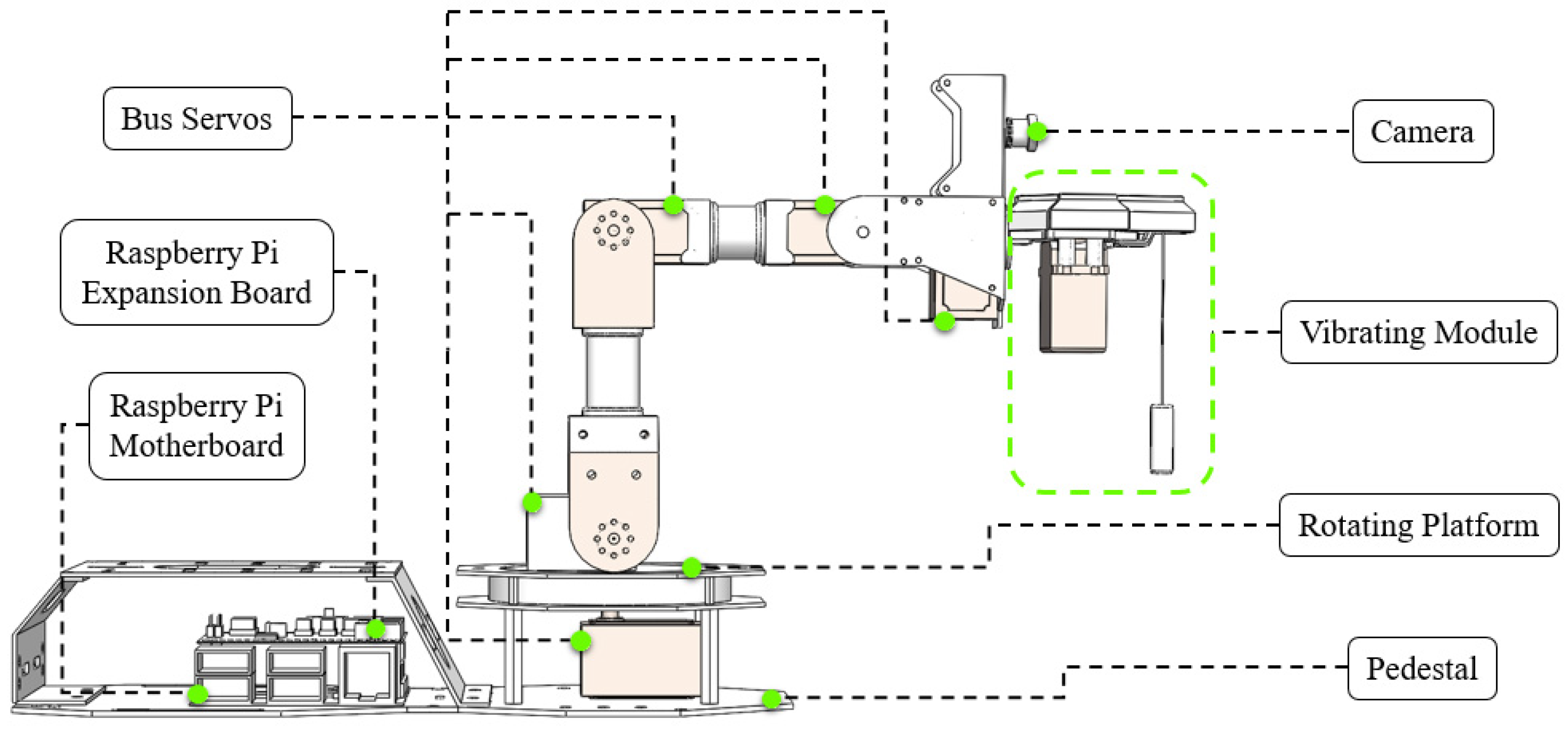
2. Vibrating Robot Arm System

2.1. Vibro-Module

A vibro-module with a single degree of translational freedom has been created to fulfill the specified needs for vertical insertion and extraction of vibrators. This module features a gear transmission that is driven by a bus servo, enabling power and motion to be transmitted between parallel shafts through parallel shaft cylindrical gearing. The vibrator lead runs through the auxiliary retractor and is partly secured to the gear drive, allowing for vertical insertion and extraction. This setup ensures compliance with the specifications for vertically inserting and extracting concrete. The structural model of the vibro-module is constructed by integrating the gear drive, vibrator, bus servo, and auxiliary connectors. Figure 1 can be referred to as an exploded view of the structure.

2.2. Structural Model of the Vibrating Robot Arm

The robotic arm module offers four rotational degrees of freedom and loads the Raspberry Pi 4B control system on the left side of the base. Positioned above the base are the rotating platform and three linking rods interconnected by joints. The angle adjustments between adjacent rods are controlled by bus servos associated with the central joints. The end joints load the camera and the vibro-module. Together, these mechanical components, bus servos, camera, and vibro-module comprise the robotic arm’s structural model, as illustrated in Figure 2.

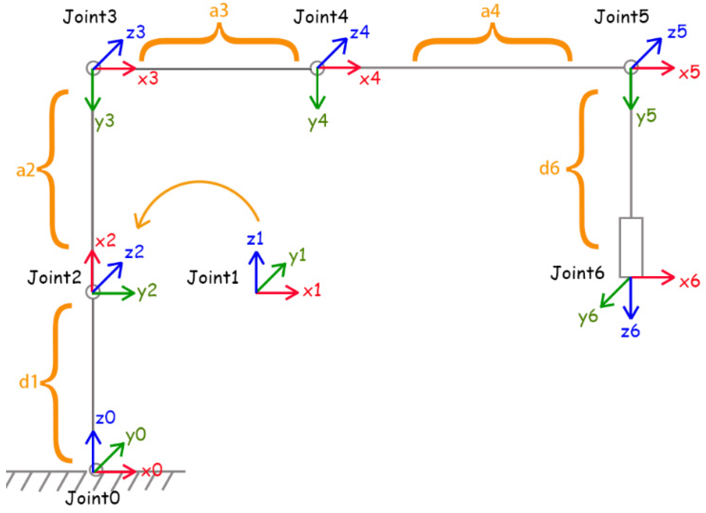
2.2.1. Model Space Description

Currently, the vibrator position is primarily determined using sensors and a positioning system, which are susceptible to environmental interference. By utilizing the kinematic model of the vibrating robotic arm system, the interference from the environment on the sensors and positioning system can be significantly reduced. This model integrates geometric parameters and transformation matrices to enhance the accuracy of obtaining the vibrator’s endpoint position information. This provides information support for further automated control.
The kinematic model of a vibrating robot arm based on machine vision can be described in pixel space, Cartesian space, joint space, and actuator space. Pixel space refers to the image captured by the camera, described using pixel coordinates ( x , y ). Cartesian space refers to the specific position ( X , Y , Z ) and posture ( α , β , γ ) of the point coordinates based on the base coordinates of the robotic arm. The joint space refers to the abstract model of the vibrating robot arm system, described by the rotation angle ( θ i ) of each joint and the translation distance ( d i ) of the vibro-module. When transforming joint space to actuator space, it is important to consider the positioning of the actuator and the joint structure. In a vibrating robot arm system, the driver space corresponds to the PWM pulse width determined through the linear interpolation of the servo rotation angle. Pixel space to Cartesian space conversion is facilitated by camera calibration parameters and a hand–eye transformation matrix. The transition between Cartesian space and joint space is accomplished through both forward kinematics and inverse kinematics models. Lastly, converting between joint space and actuator space involves linear interpolation mapping of the PWM pulse width to the servo rotation angle. The transformation relationship of these four spaces is shown in Figure 3.

2.2.2. Forward Kinematics

The length of each link is known, assuming that the base coordinate system of the vibrating robot arm is Joint0 and the coordinate system of each joint and the end of the vibrator are Joint1, Joint2, Joint3, Joint4, Joint5, and Joint6, respectively. The simplified linkage coordinate system is shown in Figure 4.
The improved DH parameter list is obtained based on the vibrating robot arm linkage coordinate system model, as shown in Table 1.
The kinematic model is established based on the improved DH parameter table [28]. The transformation matrix T 1 0 , T 2 1 , T 3 2 , T 4 3 , T 5 4 , and T 6 5 between adjacent coordinate systems is obtained. Then, the transformation matrix is sequentially multiplied to obtain T 6 0 , which contains the position and posture of the end coordinate system of the vibrator relative to the base coordinate system of the vibrating robot arm, i.e.,
T 6 0 = T 1 0 T 2 1 T 3 2 T 4 3 T 5 4 T 6 5
The abbreviated form for the sake of simplicity of the subsequent formulas is defined as follows:
s i j k = sin ( θ i + θ j + θ k ) c i j k = cos ( θ i + θ j + θ k )
R 6 0 is the rotation matrix of the vibrator end coordinate system with respect to the base coordinate system of the vibrating robot arm, i.e.,
R 6 0 = s 1 s 6 + c 1 c 234 c 6 s 1 c 6 c 1 c 234 s 6 c 1 s 234 s 1 c 234 c 6 c 1 s 6 s 1 c 234 s 6 c 1 c 6 s 1 s 234 s 234 c 6 s 234 s 6 c 234
P 6 0 is the origin of the vibrator end coordinate system relative to the coordinates under the base coordinate system of the vibrating robot arm, i.e.,
P 6 0 = ( a 2 c 2 + a 3 c 23 + a 4 c 234 d 6 s 234 ) c 1 ( a 2 c 2 + a 3 c 23 + a 4 c 234 d 6 s 234 ) s 1 a 2 c 2 a 3 s 23 a 4 s 234 + d 1 d 6 c 234
The simplified T 6 0 is
T 6 0 = R 6 0 P 6 0 0 1

2.2.3. Inverse Kinematics

The inverse kinematics of the vibrating robot arm is to derive the angle of rotation angle of each joint ( θ 1 , θ 2 , θ 3 , θ 4 and θ 6 ), combining analytical and geometrical methods to solve for the angle of rotation of each joint with the known position of the end point of the vibrator in the base coordinate system of the vibrating robot arm. The angle of rotation of each joint is solved by combining analytical and geometrical methods.
Assuming that the pitch and roll angles of the vibrator end coordinate system are β and γ , respectively, the position of the vibrator end point in the base coordinate system of the vibrating robot arm is
P 6 0 = x 6 0 y 6 0 z 6 0
If both x 6 0 and y 6 0 are zero, θ 1 takes any value within the joint restricted angle; if neither x 6 0 nor y 6 0 is zero, it is straightforward to solve for θ 1 , i.e.,
θ 1 = a t a n 2 ( y 6 0 , x 6 0 )
Knowing θ 1 and eliminating the effect of θ 1 on the equation, the vector obtained by inverse multiplying P 6 0 by T 1 0 is equal to the translation vector in T 6 1 . The rotation vectors expressed by β and γ are equal to the rotation vector expressed by the joint angle θ i in T 6 1 , i.e.,
P 6 1 l e f t = ( T 1 0 ) 1 P 6 0 R 6 1 l e f t = R Y ( β ) R Z ( γ ) T 6 1 = T 2 1 T 3 2 T 4 3 T 5 4 T 6 5 = R 6 1 r i g h t P 6 1 r i g h t 0 1 P 6 1 l e f t = P 6 1 r i g h t R 6 1 l e f t = R 6 1 r i g h t
Accessible
θ 2 + θ 3 + θ 4 = β π θ 6 = γ π
Substituting into Equation (8) yields for solving, i.e.,
θ 3 = a t a n 2 ( 1 c o s ( θ 3 ) 2 , c o s ( θ 3 ) ) , θ 3 > 0 θ 3 = a t a n 2 ( 1 c o s ( θ 3 ) 2 , c o s ( θ 3 ) ) , θ 3 < 0
Included among these are
c o s ( θ 3 ) = b 1 2 + b 2 2 a 2 2 a 3 2 2 a 2 a 3 b 1 = x 6 1 a 4 c o s 234 + d 6 s 234 b 2 = z 6 1 a 4 s i n 234 d 6 c 234
Knowing θ 3 , it is straightforward to solve for θ 2 and θ 4 as
θ 2 = a t a n 2 ( b 2 , b 1 ) a t a n 2 ( K 2 , K 1 ) θ 4 = β π θ 2 θ 3
Included among these are
K 1 = a 2 + a 3 c 3 K 2 = a 3 s 3

3. Machine Vision Integration Algorithms

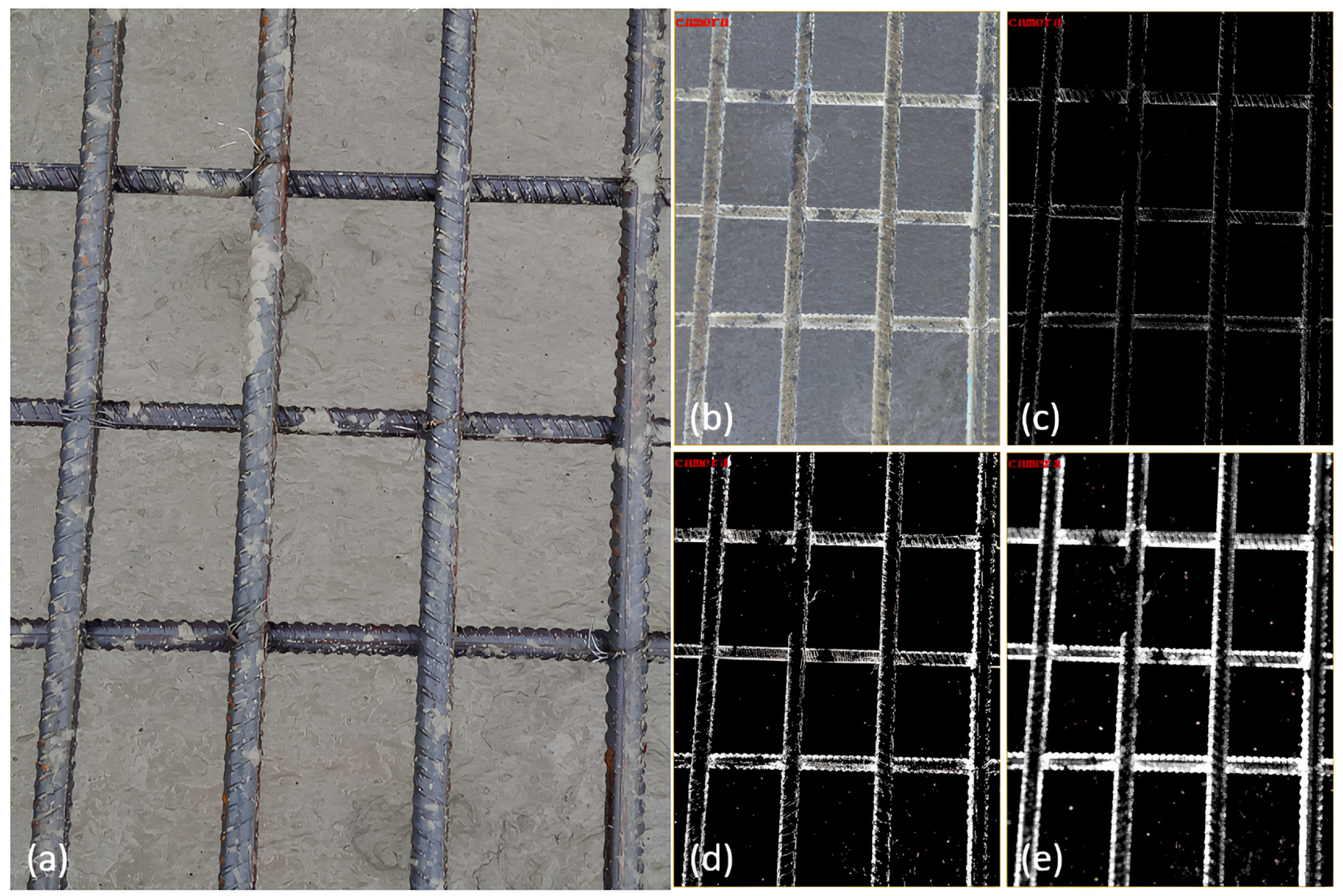
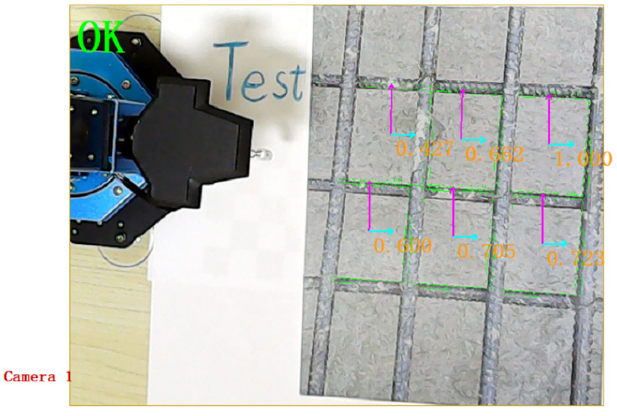
3.1. Rebar Grid Center Point Identification

Based on the machine vision algorithm [29], the original image illustrated in Figure 5a was captured by the camera undergoes an integrated preprocessing algorithm. This step involves grey scale inversion as illustrated in Figure 5b, contrast adjustment as illustrated in Figure 5c, image binarization as illustrated in Figure 5d, and morphological transformation as illustrated in Figure 5e [30]. Following this preprocessing step, data volume can be decreased, vision algorithm processing speed enhanced, irrelevant detection information in the original image substantially eliminated, and image visualization enhanced. Additionally, the detectability of feature information is restored and boosted, thereby improving the subsequent recognition the algorithm’s reliability.
The integration of shape-matching algorithms is carried out for situations where the grid shape in the reinforcing steel mesh is predominantly rectangular. This integrated algorithm can detect geometries with similar shape attributes. The algorithm establishes the center point of the rebar grid as the center point of the matching source, as illustrated in Figure 6a. By utilizing the shape-matching algorithm, the centroids of all areas in the original image matching the source are determined, i.e., the pixel coordinates of the centroids of each rebar grid in the original image, as depicted in Figure 6b.

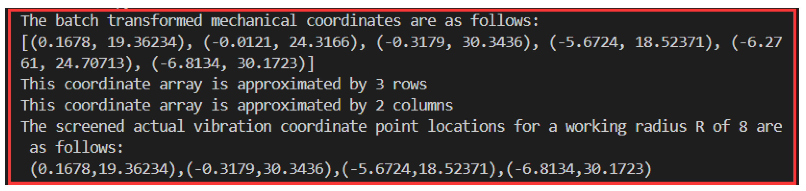
3.2. Batch Coordinate Conversion and Screening

The machine vision integration algorithm is based on camera calibration and hand–eye calibration, converting pixel space to Cartesian space using camera calibration parameters and hand–eye transformation matrix. These parameters are essential for coordinate system calibration and batch coordinate transformation. They enable the transformation between the camera and robot arm base coordinates. In Section 3.1, the algorithm obtains pixel coordinates of the rebar grid’s center in the original image. These coordinates are then used in the batch coordinate conversion algorithm, with ‘top’ and ‘left’ priorities. This aids in the vibration point screening algorithm implementation. Finally, the center point of the rebar grid is obtained in an orderly manner relative to the mechanical coordinates of the robot arm base coordinates. The flowchart of the vibration point screening algorithm is shown in Figure 7.

3.3. Vibratory Quality Judgement Model

The control of concrete vibration quality mainly relies on the supervisory bystander type and worker self-inspection type [31]. However, this type of determination is associated with subjectivity and lagging, which easily cause omission, wrong judgment, and late judgment. It will directly lead to leakage, under-vibration, and over vibration during vibration operation, indirectly leading to quality problems after the concrete is molded. It is difficult to cover the large-scale quality inspection needs [32]. To address the above problems, the YOLOv5 target detection model based on the image feature information of concrete surfaces is proposed. The model is able to identify and classify the concrete surface images in the visualization area, so as to achieve the determination of vibration quality.

Modeling of Vibratory Quality Determination
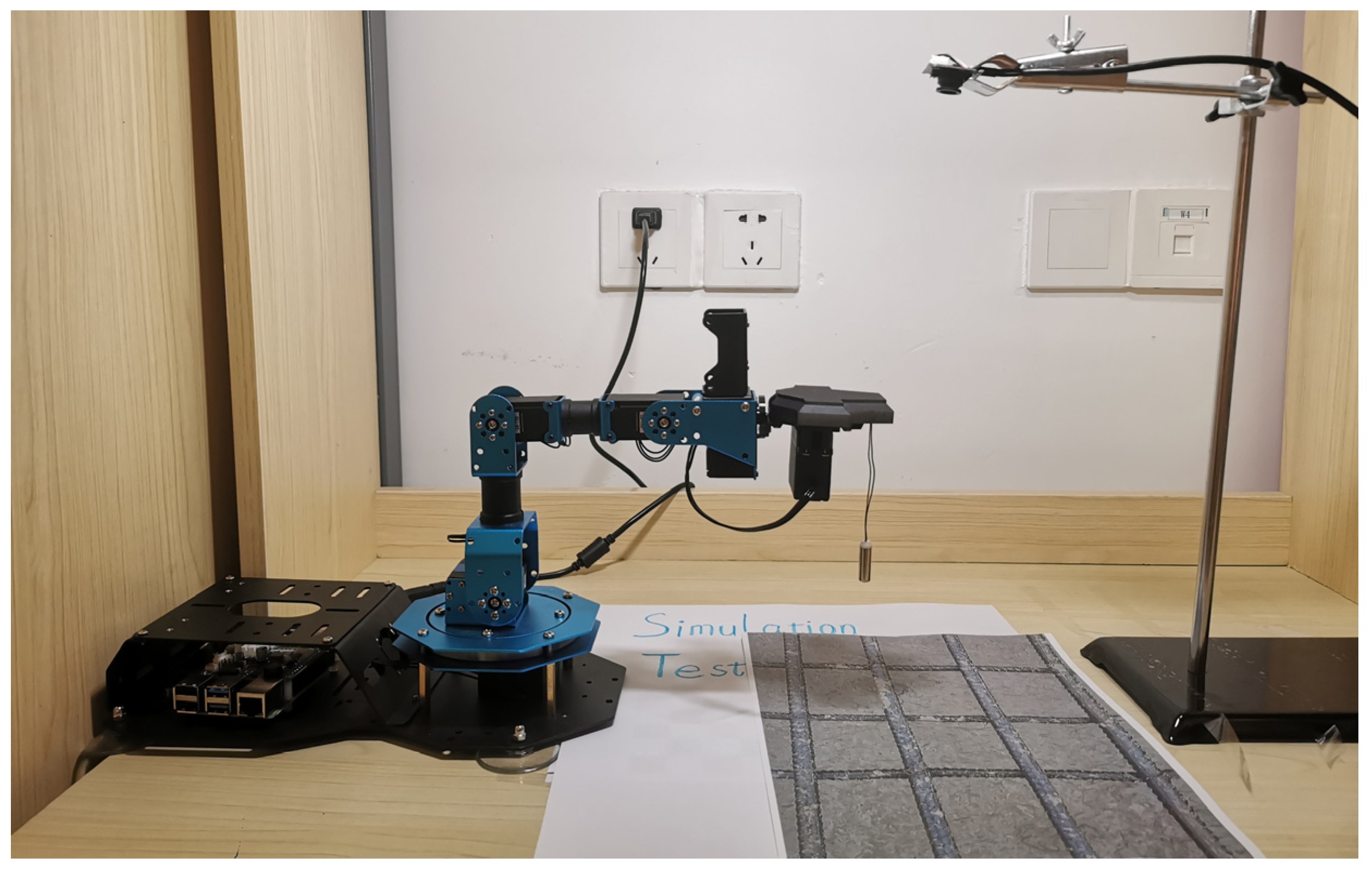
The evaluation of vibration quality is influenced by factors such as the training set size and iteration numbers, affecting both model performance and convergence speed. Currently, there is a scarcity of training data and well-developed models for assessing concrete vibration quality. Additionally, the manual collection of photos is limited, making it challenging to create the comprehensive training sets required for model training. To address this, a method is proposed to expand the training set using the existing limited data. This method involves rotating each image in the training set by 1° for 359 iterations. By applying this operation algorithmically, the training set size can be increased from n pictures to 360 × n images, as illustrated in Figure 8.
The vibration quality determination model’s recognition results are categorized into two groups: not vibrated and vibrated. The weight coefficient, number of iterations, and batch size are configured for model training. Through the training of the model, the determination of vibration quality can be achieved.

4. Simulation Tests

Build a simulation test environment. The machine vision integration algorithm, vibrating point screening algorithm, vibrating quality determination model, and kinematic model of the vibrating robot arm system are verified and analyzed in simulation tests. During the simulation test, the camera is placed outside the vibrating robot arm system, as illustrated in Figure 9.
Firstly, the machine vision integration algorithm is validated, incorporating the identification of the central coordinates of the rebar grid. The vibrating robotic arm system acquires images and implements the machine vision integration algorithm described in Section 3.1 for image processing. The outcomes demonstrate that the image preprocessing algorithm significantly improves feature-matching information within the images. Furthermore, the combination of the shape-matching algorithm enables the extraction of pixel coordinates for the center points of the rebar grid. The results are shown in Figure 10.
Next, a batch transformation algorithm, following the one described in Section 3.2, is utilized. The pixel coordinates of the rebar grid’s center point serve as an input to generate mechanical coordinates systematically. Subsequently, a vibration point screening algorithm, in alignment with vibration spacing specifications, is applied. Taking mechanical coordinates and the vibrator’s actual working radius as input, the algorithm outputs the mechanical coordinates of the vibration point. This is illustrated in Figure 11. The results demonstrate compliance with adjacent vibration point spacing requirements, covering the work area with fewer points and boosting efficiency. It also thwarts over-vibration and leakage, affirming the viability of the screening algorithm for vibration points.
Finally, the controller moves the screened mechanical coordinates in accordance with the description and transformation of the kinematic model of the vibrating robotic arm in the four spaces. The vibrator’s endpoints are then driven to sequentially reach the specified positions and simulated vibration operations are carried out. Simultaneously, the vibrating robotic arm system begins capturing images. A vibration quality assessment model is then used to categorize the images. The vibration operation in the area concludes when the consecutive frames in the image assessment result all fall within the vibrated category.

5. Conclusions

A vibrating robotic arm system based on automation control technology, machine vision technology, and kinematic modeling is proposed. The intelligent vibration of concrete under reinforcing steel mesh is investigated and simulated, leading to the following findings.
(1)
Automatic acquisition of the center point coordinates of the rebar grid in the workspace is obtained. Batch gathering of pixel coordinates and batch conversion of the rebar mesh point coordinates are accomplished through machine vision integration algorithms.
(2)
Automated screening of precise vibration point locations within the workspace is accomplished. The vibration point screening algorithm ensures compliance with the specified insertion spacing for adjacent vibration points.
(3)
The vibrator’s vertical attitude remains constant during operation. The vibro-module fulfills the specifications for vertical insertion and extraction of the vibrator, while also preventing collisions with the reinforcement formwork.
(4)
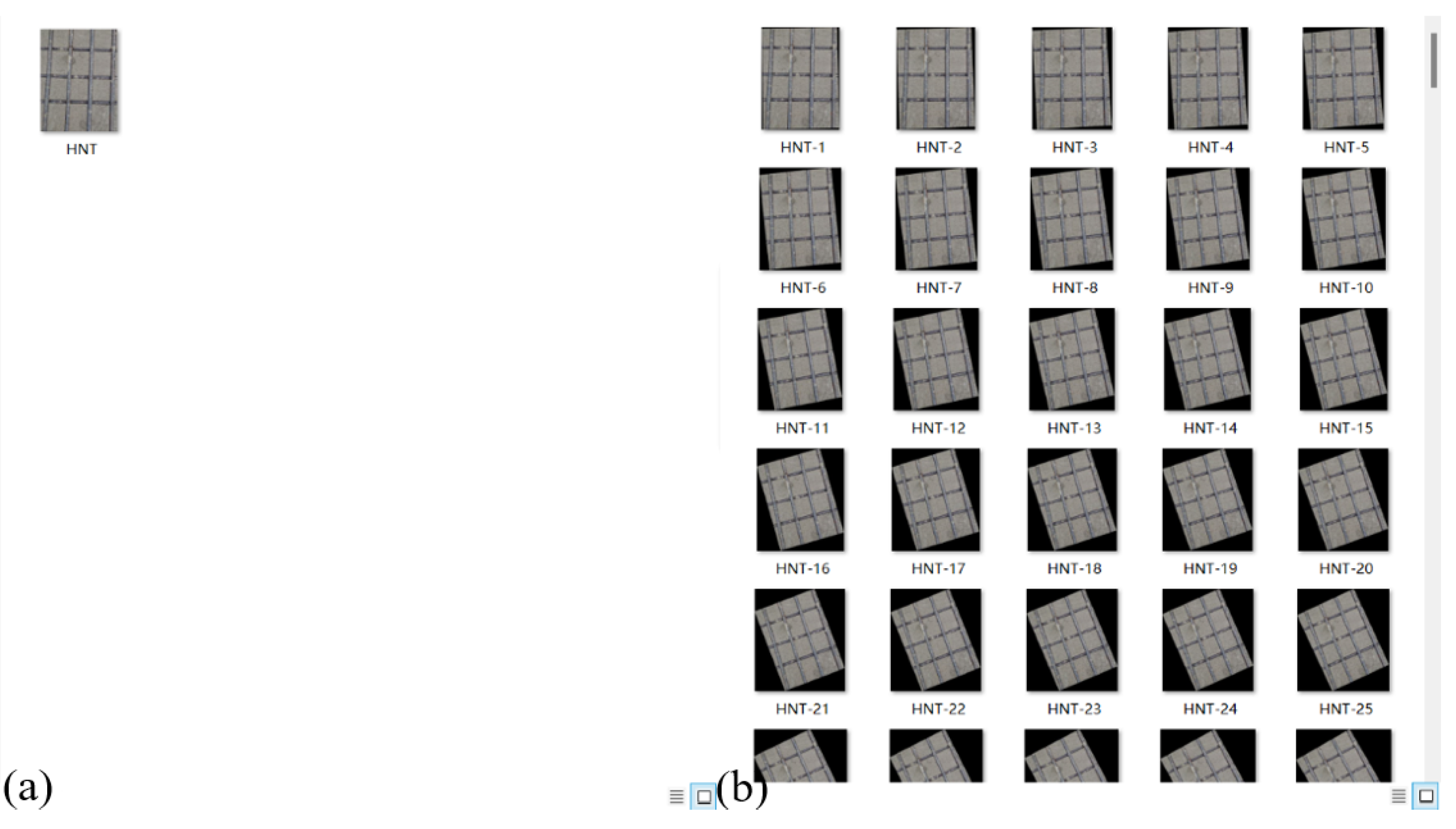
Automated assessment of vibration quality is conducted. Utilizing the YOLOv5 target detection model enables real-time evaluation of vibration quality during the vibration process, enhancing quality control standards while mitigating the unpredictability and delays associated with conventional quality assessment methods.
(5)
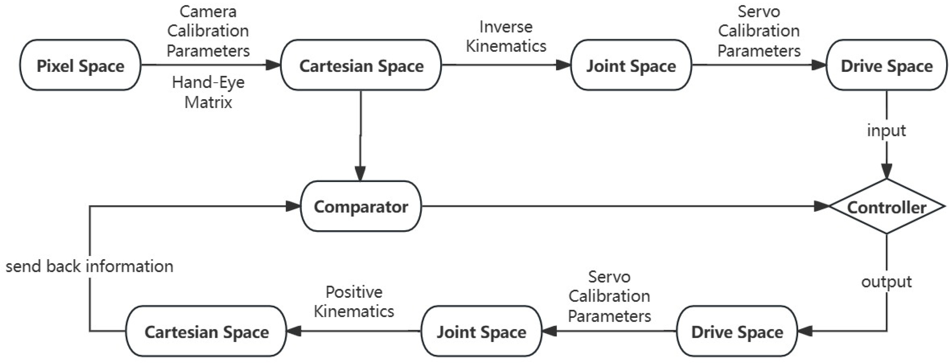
Through the closed-loop control of the spatial transformation of the vibrating robotic arm system, the accuracy of the actual operation results of the vibrating robotic arm system is improved.
(6)
The feasibility of the vibrating robotic arm system in intelligent vibration of concrete under reinforcing steel mesh is verified through simulation tests.
The research results provide a new technical solution for automated concrete vibration under reinforcing steel mesh, potentially advancing the integration of artificial intelligence in engineering. It enhances the quality control standard of the concrete construction process, optimizes the vibration task as per the specifications, and effectively accomplishes the vibration task. The vibration process is influenced by the interaction of various factors due to the intricate and variable onsite conditions. Future research endeavors should focus on enhancing the universality, precision, and efficiency of machine vision integration algorithms and vibration quality determination models. Moreover, distinct characteristics of concrete blends require specific optimal vibration frequencies and amplitudes. The current vibro-module regulates a singular vibration parameter, whereas it could potentially automatically adjust and modify the vibration parameters based on the mix’s characteristics in subsequent research.

Author Contributions

Data curation, H.L.; Funding acquisition, Z.W., J.H. and Y.G.; Investigation, H.L.; Methodology, S.Q.; Project administration, Z.W., J.H., Y.G. and S.Q.; Supervision, Z.W., J.H., Y.G. and S.Q.; Validation, H.L.; Writing—original draft, H.L.; Writing—review and editing, S.Q. All authors have read and agreed to the published version of the manuscript.

Funding

This work was financially supported by the National Natural Science Foundation of China (Grant No. 52079049).

Data Availability Statement

Data are contained within the article.

Acknowledgments

The authors are highly thankful to the National Natural Science Foundation of China.

Conflicts of Interest

Authors Zhigang Wu, Jifeng Hu and Yuannan Gan were employed by the company China Anneng Group Second Engineering Bureau Co., Ltd. The remaining authors declare that the research was conducted in the absence of any commercial or financial relationships that could be construed as a potential conflict of interest.

References

  1. Tian, Z.H.; Ma, Y.S.; Li, J.J. Research progress on concrete vibration compactness. J. Constr. Mater. 2024, 27, 46–57. [Google Scholar] [CrossRef]
  2. Basler, F.; Mähner, D.; Fischer, O.; Hilbig, H. Influence of early-age vibration on concrete strength. Struct. Concr. 2023, 24, 6505–6519. [Google Scholar] [CrossRef]
  3. Hu, J.; Qin, M.Q.; Wang, H.W.; Liu, K.X. Study on the influence law of vibration frequency on the performance of concrete. Highway 2020, 65, 111–112. [Google Scholar]
  4. Wen, J.X.; Huang, F.L.; Wang, Z.; Yi, Z.; Xie, Y.; Li, H.; Cheng, H. Research status and development trend of concrete vibration technology. Silic. Bull. 2021, 40, 3326–3336. [Google Scholar] [CrossRef]
  5. Yuan, Y.S.; Tian, Z.H.; Xu, X.B.; Liu, H.R.; Li, J.J.; Fan, H.Y. Research on response parameters and classification identification method of concrete vibration process. Materials 2023, 16, 2958. [Google Scholar] [CrossRef] [PubMed]
  6. Quan, Y.H.; Wang, F.L. Machine learning-based real-time tracking for concrete vibration. Autom. Constr. 2022, 140, 4343. [Google Scholar] [CrossRef]
  7. Gong, J.; Yu, Y.; Raghav, K.; Andrés, R. Real-time tracking of concrete vibration effort for intelligent concrete consolidation. Autom. Constr. 2015, 54, 12–24. [Google Scholar] [CrossRef]
  8. Han, J.G.; Wang, K.J.; Wang, X.H.; Paulo, J.M.M. 2D image analysis method for evaluating coarse aggregate characteristic and distribution in concrete. Constr. Build. Mater. 2015, 127, 30–42. [Google Scholar] [CrossRef]
  9. Liu, J. Development of a Stereo Vision Based Concrete Vibrating Quality Monitoring System. Master’s Dissertation, Harbin Institute of Technology, Harbin, China, 2018. [Google Scholar]
  10. Pierre, B.; Jean-Marie, G.; Younés, H. On-site concrete segregation estimation using image analysis. J. Adv. Concr. Technol. 2008, 6, 171–180. [Google Scholar] [CrossRef]
  11. Sheng, Y.S.; Fan, Q.X.; Wang, Z.L.; Chen, W.; Guo, Z.; Lin, E.; Lin, P.; Zhou, T.; Zhou, M.; Liu, C.; et al. Intelligent construction technology and application practice of Baihetan extra-high arch dam. J. Tsinghua Univ. (Nat. Sci. Ed.) 2021, 61, 694–704. [Google Scholar] [CrossRef]
  12. Jin, Y.; Pan, J.Z.; Zhong, L.; Han, Y.; Zhou, G.; Gao, X. Study on rheology and bubble structure of fresh concrete under vibration. Silic. Bull. 2023, 42, 3866–3877. [Google Scholar] [CrossRef]
  13. Zhong, G.L.; Xu, J.J.; Qiao, Y.; Zhu, Y.; Zhang, Z. Research and application of key technology for intelligent monitoring of concrete vibration quality. Water Conserv. Hydropower Technol. 2020, 51, 422–426. [Google Scholar] [CrossRef]
  14. Yang, N.; Li, J.; Zhou, S.W.; Liu, Y.Y.; Zhong, G.L. Research and application of intelligent control technology of concrete vibration for high arch dam. China Rural Water Conserv. Hydropower 2018, 8, 176–178, 185. [Google Scholar]
  15. Tian, Z.H.; Bian, C.; Mao, L.; Wu, Y.J. Development of dynamic visualization monitoring system for concrete vibration. J. Build. Mater. 2013, 16, 508–513. [Google Scholar]
  16. Li, Z.W.; Zhang, S.P.; Niu, Y.Z.; Li, Y. Concrete vibration technology and intelligent development of precast box girder for high speed rail. J. Railw. Sci. Eng. 2024, 39, 1–10. [Google Scholar] [CrossRef]
  17. Zhong, D.H.; Shen, Z.Y.; Wang, J.J.; Cui, B.; Ren, B.; Wang, D. Research on dynamic evaluation of concrete dam vibration construction quality based on real-time monitoring. J. Water Resour. 2018, 49, 775–786. [Google Scholar] [CrossRef]
  18. Lee, S.G.; Skibniewski, M.J. Monitoring of concrete placement and vibration for real-time quality control. Proc. Creat. Constr. Conf. 2019, 011, 67–76. [Google Scholar] [CrossRef]
  19. Yangtze River Institute of Surveying, Planning and Design. Specification for Hydraulic Concrete Construction; China Water Conservancy and Hydropower Press: Beijing, China, 2014. [Google Scholar]
  20. China Electricity Council. Hydraulic Concrete Construction Specification; China Electric Power Press: Beijing, China, 2015. [Google Scholar]
  21. Chu, Y.D.; Li, C.G.; Chen, F.X.; Wang, J.; Yue, Y.S. A review on the development of concrete leveling vibrating machine. Water Conserv. Hydropower Technol. 2020, 51, 99–110. [Google Scholar] [CrossRef]
  22. Zhong, D.H.; Ren, B.Y.; Song, W.S.; Wu, B.; Guan, T.; Tong, D. Research on key technology of intelligent control of progress and quality of high arch dam construction and its application. Water Conserv. Hydropower Technol. 2020, 50, 8–17. [Google Scholar] [CrossRef]
  23. Li, M.; Li, C.G.; Qian, H.W.; Chu, Y.D. Trajectory planning of a concrete vibration robot in the reinforcing steel mesh of dam face. Mach. Electron. 2023, 41, 61–65. [Google Scholar]
  24. Wang, D.; Guan, T.; Yang, S.A.; Wang, X.; Zhai, H.; Ren, B. Intelligent monitoring of concrete vibration quality under air-ground integrated sensing. J. Silic. 2023, 51, 1219–1227. [Google Scholar] [CrossRef]
  25. Wang, X.L.; Wang, D.; Ren, B.Y.; Chen, W.F.; Tan, Y.S.; Guan, T. Development and application of concrete vibration robot system for high arch dams. J. Water Resour. 2022, 53, 631–643, 654. [Google Scholar] [CrossRef]
  26. Zhao, C.; Gao, S.Q.; Wang, J.Y.; Li, X.; Wang, S. Research on rapid construction technology of large volume pier body based on automated lifting. Build. Struct. 2023, 53, 2003–2008. [Google Scholar] [CrossRef]
  27. Deng, K.D.; Qiang, S.; Jiang, Y.B.; Xu, C.L.; Hua, X. Modeling and development of unmanned transportation and pouring system for hydraulic large volume concrete. Hydropower Energy Sci. 2022, 40, 175–179. [Google Scholar] [CrossRef]
  28. Yu, Z.; Ren, H.H.; Qin, Q.P.; Hu, K. Kinematic analysis and trajectory planning of welding robot for complex spatial paths. J. Wuhan Univ. Sci. Technol. 2023, 46, 384–392. [Google Scholar] [CrossRef]
  29. SG, Vision 4.1; Mooklab Technology Ltd: China. January 2023. Available online: https://www.mooklab.cn/SGVision (accessed on 27 March 2024).
  30. Zhang, Z.P.; Qiang, S.; Zheng, Z.X.; Du, R.N.; Ding, B.Y. Design of automatic vibration system for reinforced concrete based on STM32 and OPENMV. Autom. Technol. Appl. 2020, 39, 181–183, 186. [Google Scholar]
  31. Ren, Y.M.; Zhang, Y.N.; Li, Y. Research progress and outlook of compressed perception and its image processing applications. J. Autom. 2014, 40, 1563–1575. [Google Scholar] [CrossRef]
  32. Liu, L.J.; Zhang, M.S.; Liu, W.H.; Zhou, D. G-YOLO: An embedded small target defect detection algorithm based on improved YOLOv5. J. Hangzhou Norm. Univ. (Nat. Sci. Ed.) 2024, 23, 201–208. [Google Scholar] [CrossRef]
Figure 1. Exploded view of the vibro-module.
Buildings 14 02277 g001
Figure 2. Structural model of the vibrating robot arm.
Buildings 14 02277 g002
Figure 3. Spatial transformation flowchart of the vibrating robot arm model.
Buildings 14 02277 g003
Figure 4. Coordinate system model of the vibrating robot arm linkage.
Buildings 14 02277 g004
Figure 5. Image pre-processing. (a) Original image; (b) Inversion of grayscale; (c) Adjustment of contrast; (d) Image binarization; (e) Morphological transformation.
Buildings 14 02277 g005
Figure 6. Shape matching algorithm. (a) Matched source; (b) Results.
Buildings 14 02277 g006
Figure 7. Flowchart of the vibration point screening algorithm.
Buildings 14 02277 g007
Figure 8. Expansion of the training set: (a) original training set and (b) expanded training set.
Buildings 14 02277 g008
Figure 9. Environment of the simulation test.
Buildings 14 02277 g009
Figure 10. Identification of the center point of the rebar grid.
Buildings 14 02277 g010
Figure 11. Vibration point screening algorithm test.
Buildings 14 02277 g011
Table 1. Improved DH parameters.
Joint   Number   ( T n n 1 ) α n 1 a n 1 θ n d n
100 θ 1 d 1
2 π 2 0 θ 2 0
30 a 2 θ 3 0
40 a 3 θ 4 0
50 a 4 00
6 π 2 0 θ 6 d 6
Disclaimer/Publisher’s Note: The statements, opinions and data contained in all publications are solely those of the individual author(s) and contributor(s) and not of MDPI and/or the editor(s). MDPI and/or the editor(s) disclaim responsibility for any injury to people or property resulting from any ideas, methods, instructions or products referred to in the content.

