Article

Influence of Pile Foundation Construction on Existing Tunnels in a Metro Protection Area: Field Test and Numerical Simulation

1
College of Civil Engineering, Zhejiang University of Technology, Hangzhou 310014, China
2
Zhejiang Province Geological & Mineral Engineering Investigation Institute Co., Ltd., Hangzhou 310014, China
3
Institute of Geotechnical Engineering, School of Civil Engineering and Architecture, East China Jiaotong University, Nanchang 330013, China
4
State Key Laboratory of Performance Monitoring Protecting of Rail Transit Infrastructure, East China Jiaotong University, Nanchang 330013, China
5
Research Centre of Coastal and Urban Geotechnical Engineering, Zhejiang University, Hangzhou 310015, China
6
School of Hotel and Tourism Management, Macau University of Science and Technology, Macau 999078, China
*
Author to whom correspondence should be addressed.
Buildings 2024, 14(8), 2280; https://doi.org/10.3390/buildings14082280
Submission received: 21 June 2024 / Revised: 11 July 2024 / Accepted: 19 July 2024 / Published: 24 July 2024
(This article belongs to the Special Issue Construction in Urban Underground Space)

Abstract

:
On the basis of the Fengqi Chaoming project in Hangzhou City, Zhejiang Province, China, this paper investigates the influence of pile foundation construction on the existing tunnels in a metro protection area to ensure the stability and safety of the pile foundation construction in the area of Hangzhou Metro Line 2 through in situ pile tests and numerical simulations. The test results show that the pile foundation construction has a certain influence on the existing metro tunnels, and the degree of influence gradually decreases as the distance between the pile foundation and the metro tunnel increases. The corresponding impact level for the pile foundation at 12 m from the tunnel is 1.06 mm, and that for the pile foundation at 4.9 m from the tunnel is 1.18 mm. Different types of pile foundations also lead to different degrees of influence. The maximum settlement corresponding to triaxial cement mixing piles is 1.89 mm, while the hard-method occlusal piles is 1.18 mm. The monitoring point of the metro tunnel with the smallest distance from the pile foundation experiences the largest deformation, but several sets of deformation data meet the requirements of the deformation control index, indicating that the pile foundation construction is safe and controllable.

1. Introduction

The rapid development of Chinese cities has led to increasingly limited space above ground, which in turn has made the development and utilization of underground space particularly important. Metro tunnels are an essential part of urban transportation services. They provide efficient public transportation services to cities and usually drive the development of the surrounding areas, which improves the overall economic level of the city [1,2,3]. However, due to increasing urbanization, other infrastructures, such as high-rise buildings, overpasses, and elevated structures, are being constructed. Within the limited urban space, the construction of these infrastructures will inevitably affect the existing tunnels. Therefore, it is necessary to study the influences of neighboring infrastructure construction on existing tunnels.
A number of current studies have investigated the influences of tunnel [2,3,4,5,6,7] and bridge construction [8,9], pit excavation [10,11,12,13,14], seismic waves [15], and traffic loading [16] effects on the existing tunnels. Model tests [17,18,19,20,21], numerical simulations [22,23,24,25,26], and theoretical derivations [6,14,27,28] have been widely used in the study of the effects of the construction of surrounding infrastructures on the existing tunnels. These studies generally revealed that the construction of surrounding infrastructures affects the existing tunnels, and thus predicted the possible differential settlement or uneven deformation of the existing tunnels. Also, these studies proposed various methods to ensure the safe operation and long-term maintenance of the existing tunnels.
Pile foundation is extensively adopted for high-rise buildings, bridges, roads, and other infrastructures [29,30,31,32,33,34]. In urban areas with an extensive distribution of infrastructure, it is necessary to fully consider the impact of pile foundation construction on nearby existing tunnels. Although the problem has been recognized in London since the 1950s, there are limited studies on the influence of pile construction on nearby existing tunnels [19,35,36]. Experimental studies regarding the influence of pile construction on nearby existing tunnels have been conducted to replicate the actual pile construction and to generate deformation data for the existing tunnels, but the scale of the experiments is too small to recover the actual effects of pile construction on the existing tunnels [18,37,38,39,40]. Theoretical analyses are commonly conducted to investigate the principles and nature of the influence of pile foundation construction on nearby existing tunnels. These studies are usually based on simplified assumptions of conventional engineering situations to facilitate the application of results by engineers in actual projects. However, there are often limitations in the application of these theories in the face of special construction contexts or different soil conditions [41,42,43,44,45,46,47]. With the development of computer technology, numerical simulations have gradually been applied to predict the influence of pile foundation construction on the existing tunnels. Due to the ability to simulate specific strata and special working conditions, numerical simulations often have strong application value and practical significance in actual projects.
The current study is performed based on the Fengqi Chaoming project in Hangzhou, Zhejiang Province, China. The construction area of this project involves the Hangzhou Metro Line 2, and a large number of pile foundations need to be constructed between the upbound and downbound metro tunnels of the Hangzhou Metro Line 2. Due to the close distance between piles and tunnels and the difficulty of the construction, it is necessary to study the influence of pile foundation construction on the metro tunnels to ensure the stability and safety of tunnel structure. In this paper, in situ pile tests are conducted to obtain the measured results of the actual pile foundation construction. Also, three-dimensional numerical simulation is undertaken to simulate the in situ test of test piles using the finite element analysis software Midas GTS NX 2022. The reliability of the numerical simulation is verified by the measured results. The numerical simulation also focuses on the analysis of the influencing factors not involved in the field test, which both makes up for the shortcomings of the field test and makes the simulation results more comprehensive. The research results can provide a case base and effective reference for similar projects in the future.

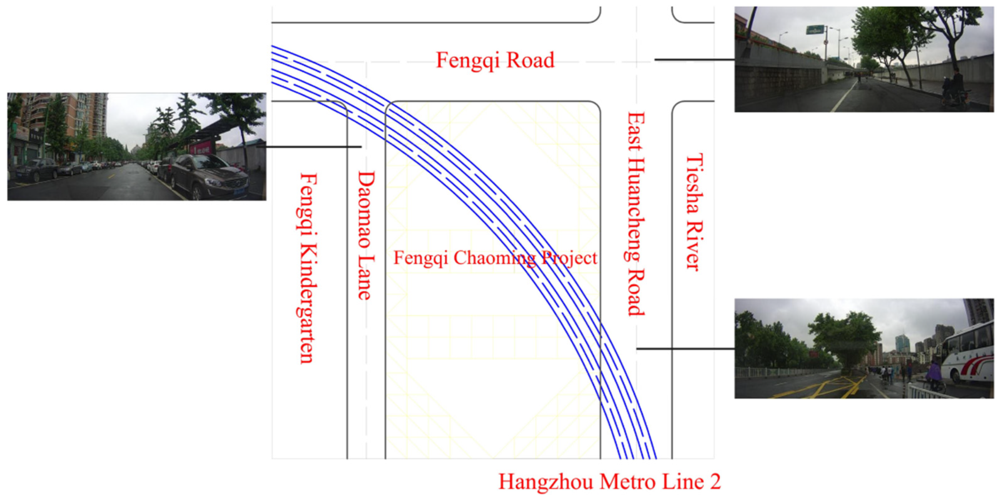
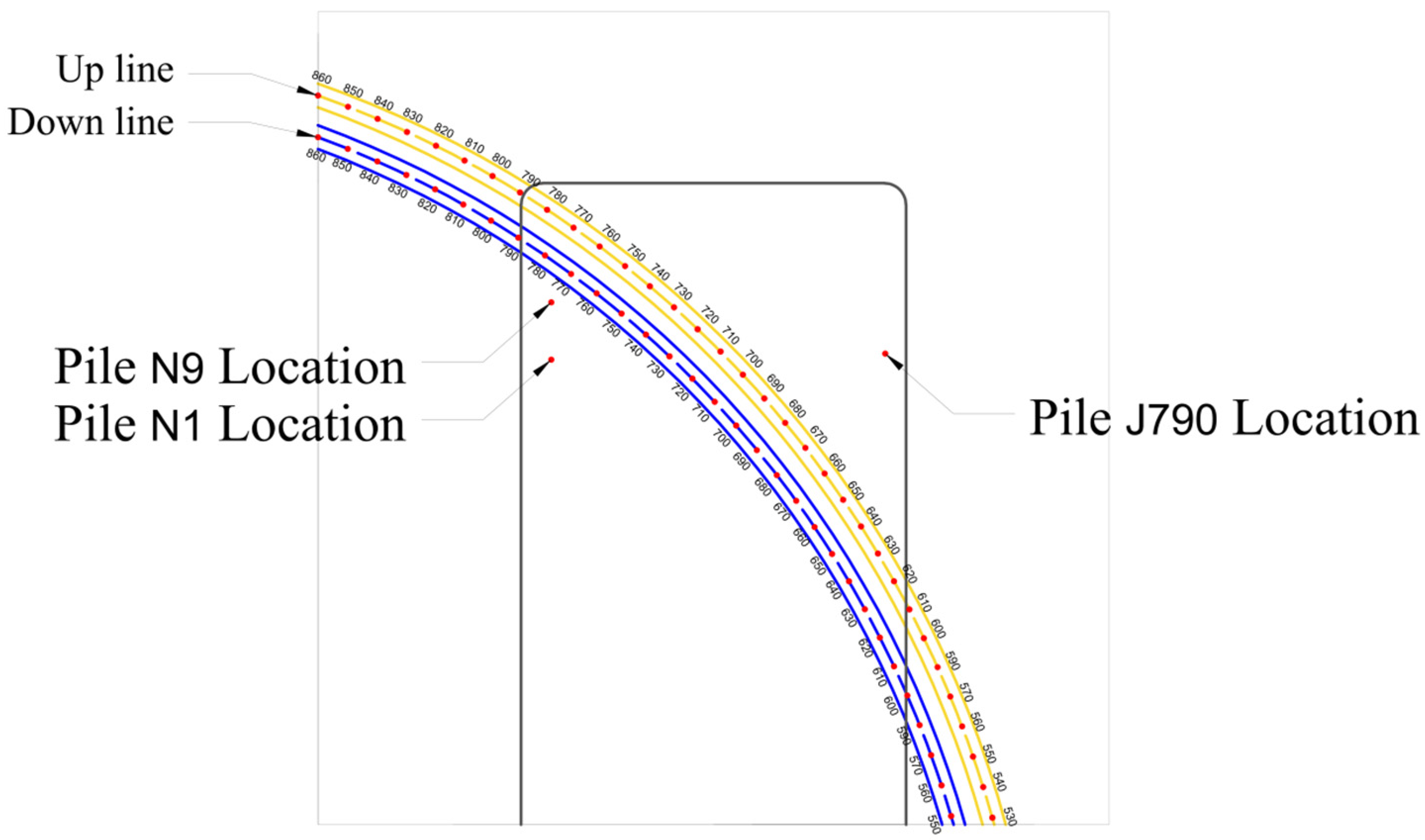
2. Engineering Background

The pile foundation and Fengqi Chaoming Project are located at the southeast corner of the intersection of Fengqi Road and Knife Mao Lane in the lower part of Hangzhou, which is bordered by the Fengqi Kindergarten on the west side and is adjacent to the East Huancheng Road, as well as the Paste Sha River, on the east side. The total land area of the project is 20,380 square meters. The relationship between the construction site of this project and the metro tunnels is shown in Figure 1.
The shield tunnel of the Hangzhou Metro Line 2 has a circular cross-section, its concrete grades are C50, with an outer diameter of 6.2 m and an inner diameter of 5.5 m. The lining is made of 0.35-metre-thick assembled segments. The Hangzhou Metro Line 2 traverses the construction site of the project, where the two metro shield tunnels are currently in operation. A number of pile foundation construction works are required between the upbound and downbound tunnels of the Hangzhou Metro Line 2. The metro shield tunnel is extremely sensitive to deformation, with millimeter-level deformation control indexes. Once the deformation exceeds the control index, it will definitely affect the operation safety and the planned opening time. Therefore, this project needs to take effective measures to control soil disturbance and minimize the influence of various factors on the metro shield structure during construction. The requirements for metro tunnel deformation are shown in Table 1.

3. In Situ Test

3.1. Test Method

In this paper, in situ pile tests are conducted to investigate the influence of pile foundation construction on the tunnels of the Hangzhou Metro Line 2 in the construction area of the Fengqi Chaoming project. The in situ tests in the metro protection area are conducted to monitor the settlements and convergence deformations of the metro shield tunnels after the test piles are driven into the design pile foundations. The monitoring data are used to assess the influence of each construction step on the metro shield tunnel to ensure a safe and controlled pile foundation construction process.

3.2. Geological Parameters of Test Pile Site

According to the drilling results, the thickness of the quaternary system is significant in the project area. Within the exploration depth of 50 m, seven engineering geological layers are identified based on the stratigraphic structure, lithological characteristics, burial conditions, and physical and mechanical properties exposed by the drill holes. The type of each engineering geological layer from top to bottom within the depth of pile construction and the soil parameters is shown in Table 2.
The in situ tests of test piles in this paper include two types of pile foundations: triaxial cement mixing (TCM) piles and hard-method occlusal (HMO) piles. The pile locations, as well as the selection and arrangement of monitoring points for TCM and HMO piles, are presented in Figure 2 and Figure 3.

3.3. Parameters and Detection of Test Piles

In this paper, three TCM piles are used for in situ pile tests. The parameters of the tested TCM piles are shown in Table 3. The in situ tests of the TCM piles are carried out at a sinking speed of 1.0 m/min for the drilling rod, a lifting speed of 1.3 m/min for the spouting, a mixing amount of 22% for the cement, and an air-stirring ratio of 11%.
In this paper, two HMO piles are used for in situ pile tests. The parameters of tested HMO piles are listed in Table 4. The drilling speed of this in situ pile test is about 5 m/h with dry soil extraction. The sinking depth of the 5-cm-thick steel shield is 3 m deeper than the drilling depth, and it is lifted when filling concrete. The construction duration of whole pile (plain pile, excluding cage lowering time) is 8 h.

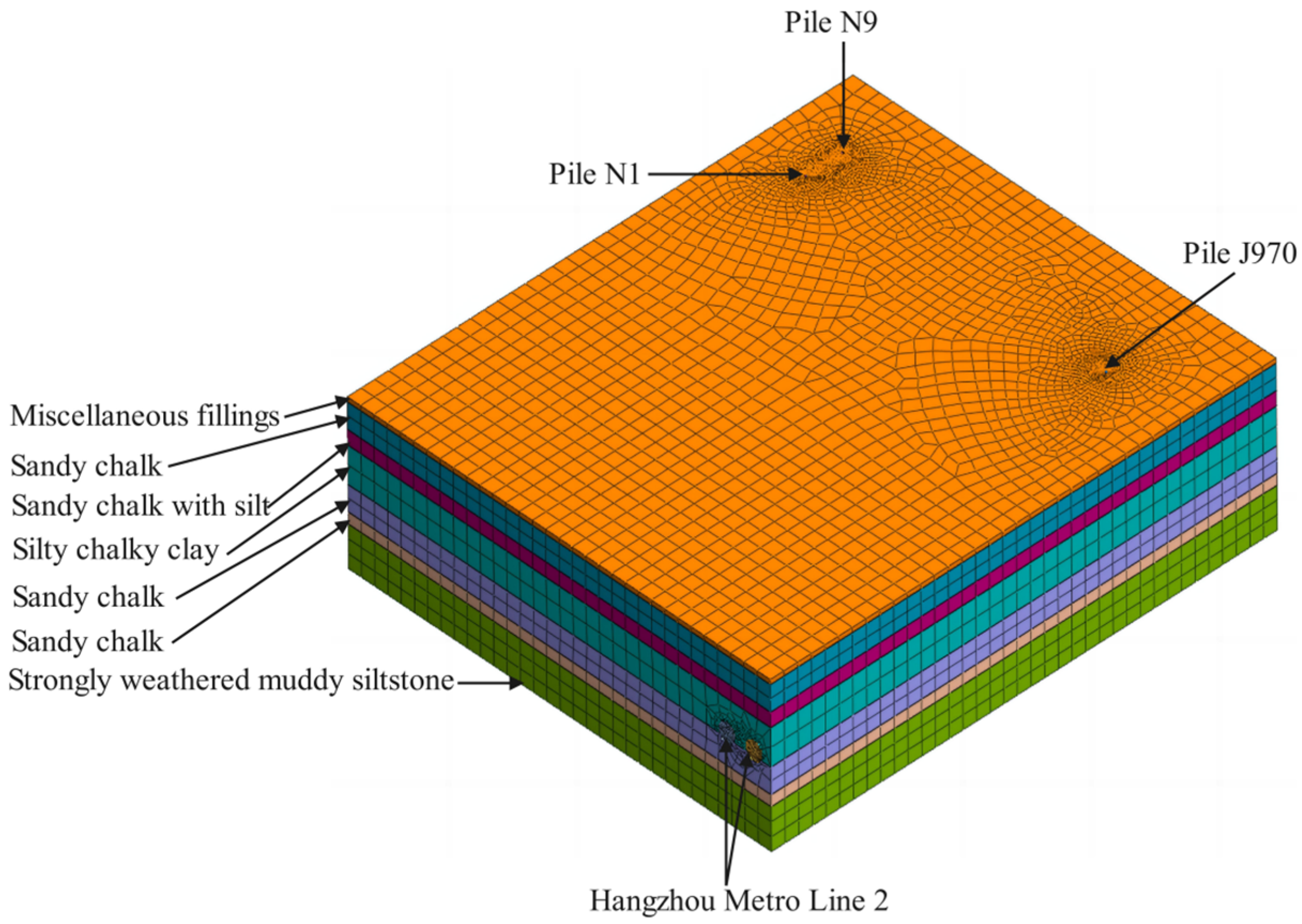
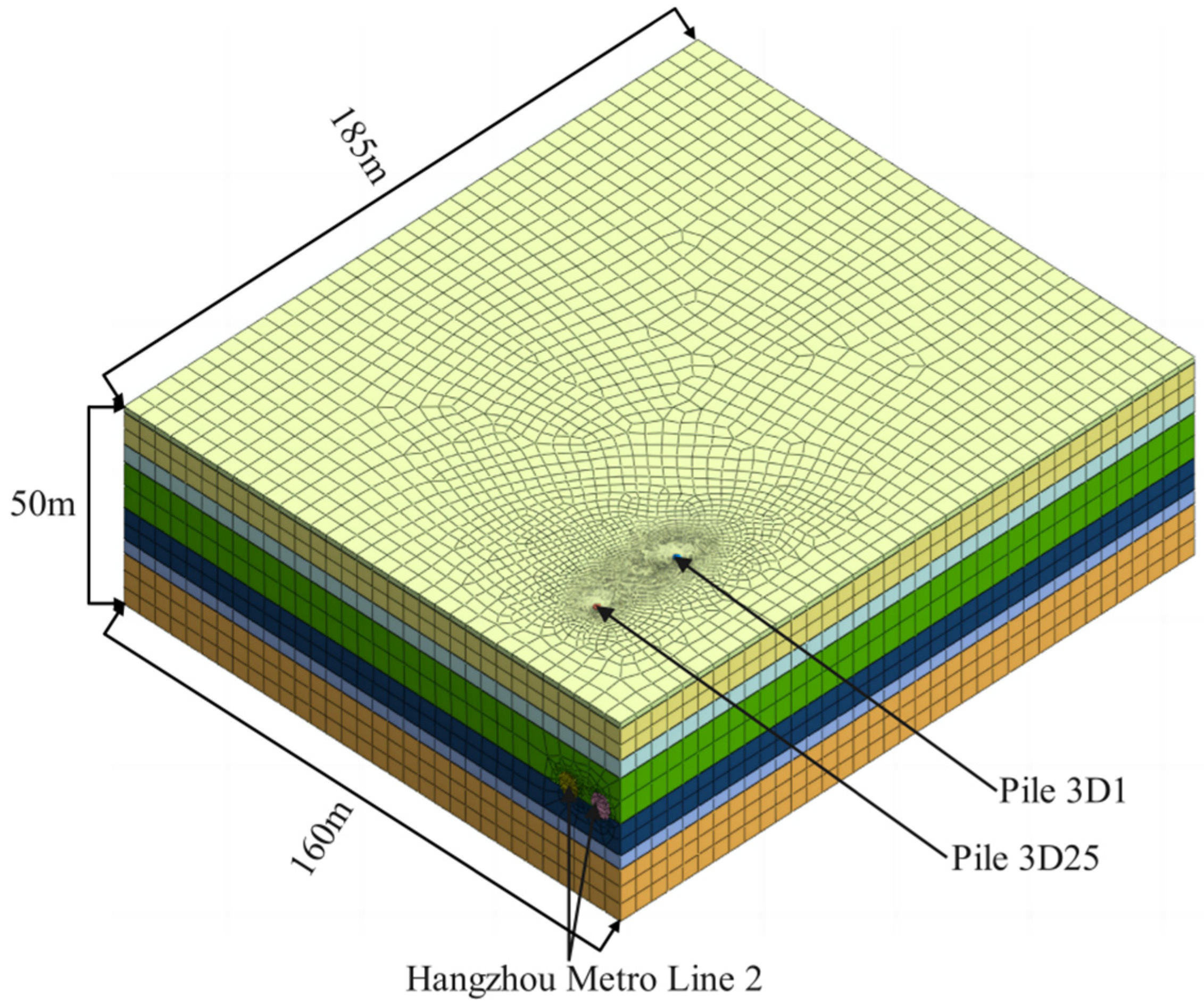
4. Three-Dimensional Finite Element Analysis

4.1. Model Parameter

The study aims to accurately analyze the influences of pile foundation construction on nearby existing metro tunnels, where the spatial effects of pile foundation construction are fully considered. For this purpose, Midas GTS, a general-purpose finite element analysis software, is used for 3D modeling.
According to the influence range of the pile foundation construction on the nearby existing metro tunnels, the dimension of the 3D finite element model is 160 m in the X direction, 185 m in the Y direction, and 50 m in the Z direction. The engineered geological layers were selected to be consistent with the geological parameters of the test pile site.
The test pile foundation consists of three TCM piles and two HMO piles. The diameters of the TCM piles are all 0.85 m, two of which are drilled to a depth of 15.5 m, with distances of 20.3 m and 8.4 m from the metro tunnels, and the other one is drilled to a depth of 20.5 m, with a distance of 40 m from the metro tunnels. The two HMO piles are both 1.0 m in diameter and drilled to a depth of 25 m, with distances of 12 m and 4.9 m from the metro tunnels. In this study, concrete grades for all piles are C40 with an elasticity modulus of 3.25 × 10⁴ MPa, a Poisson’s ratio of 0.2, and a volumetric weight of 24.39 kN/m3. The depth of the shield tunnel of the Hangzhou Metro Line 2 is 24 m. It adopts the 0.35-m-thick assembled segments as the lining. The strength grade of the lining concrete is C50, with an elasticity modulus of 3.55 × 10⁴ MPa, a Poisson’s ratio of 0.2, and a volumetric weight of 25 kN/m3. The model parameters of soil, pile foundation concrete, and metro tunnel lining are summarized in Table 5, Table 6 and Table 7.

4.2. Model Establishment

According to the model parameters, two 3D finite element models are established in this study to investigate the influences of pile foundation construction on existing metro tunnels by using the test pile foundations as TCM or HMO piles, respectively. In terms of meshing, to ensure the accuracy and reliability of the model, the seed spacing is set to 5 m for the soil body, 0.5 m for the existing metro tunnel lining, and 0.1 m for the pile foundation in both models. Specifically, the total number of elements in the 3D model of the TCM pile is 671,985, while that of the HMO pile is 917,808. The upper surface of the model is set as a free surface, while there are fixed constraints on the lower and lateral surfaces. The operation steps for establishment and calculation of the model are as follows: First, calculate the initial stress field to simulate the initial geo-stress and the initial equilibrium state of the soil body. Second, excavate the tunnel and activate the lining segment to simulate the constructed metro tunnel. Third, reset the displacement to 0 mm. Fourth, excavate the test pile and activate the pile foundation, and then calculate the deformation and internal force, etc., of existing metro tunnels. The 3D models for investigating the influences of the TCM and HMO piles on existing metro tunnels are displayed in Figure 4 and Figure 5, respectively.

5. Data Analysis and Discussion
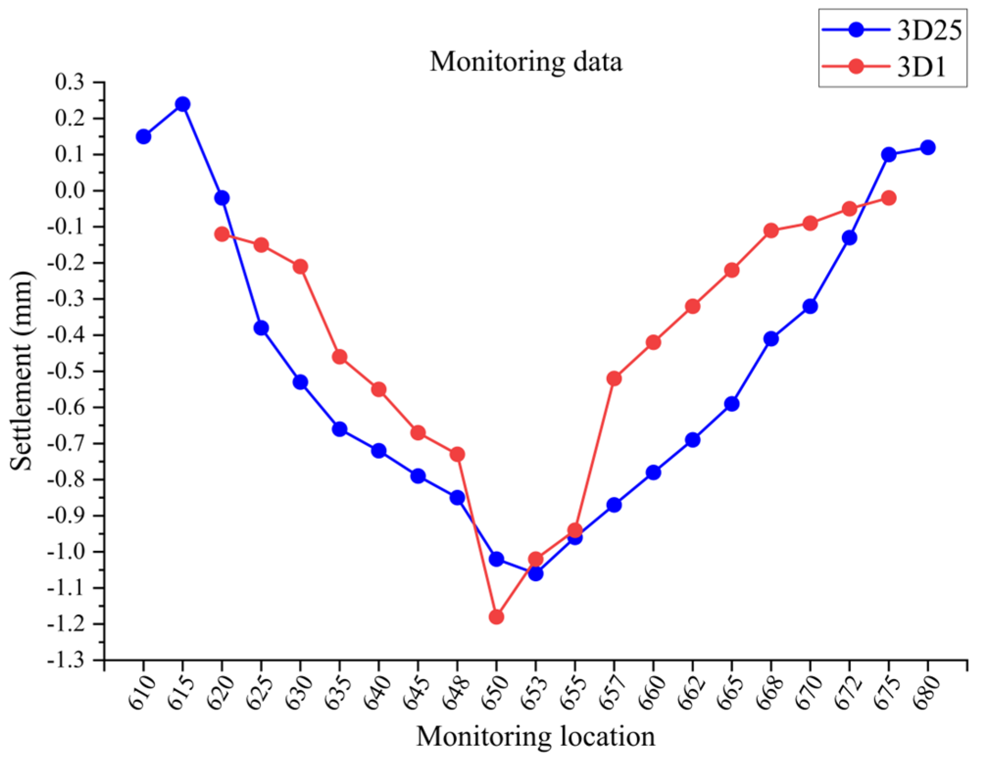
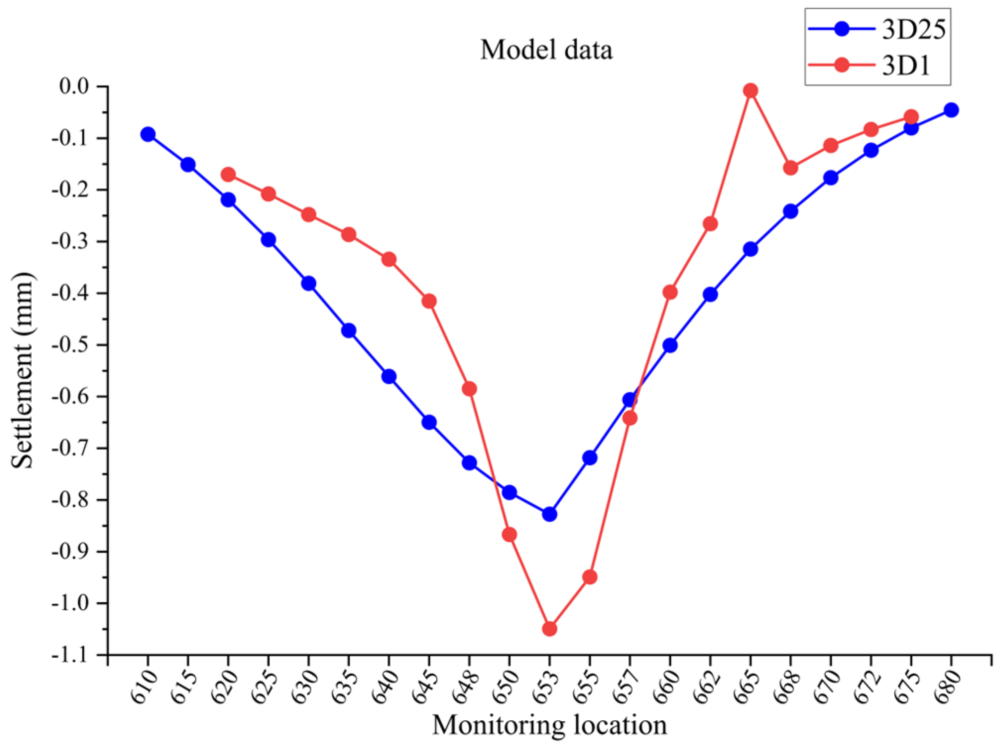
5.1. TCM Pile

The three TCM piles are numbered as J790, N1, and N9. The construction of the test pile J790 started on 20 July. Based on the influence area of pile foundation construction on the existing metro tunnel, the monitored settlement data of the upbound metro tunnel at the monitoring points 670–735 were selected for analysis. The results show that the maximum settlement of 1.22 mm occurs at the monitoring point SGCX695. The construction of test piles N1 and N9 started on 22 July, and monitored settlement data of the downbound metro tunnel at the monitoring points 750–800 were selected for analysis. The results reveal that the maximum settlement of 1.89 mm occurs at the monitoring point SGCX775.
Numerical analysis is performed to explore the influence of TCM piles on the existing metro tunnels. The numerical settlement data of the metro tunnel corresponding to test pile J790 are shown in Figure 6, in which the maximum settlement of 1.25125 mm occurs at the monitoring point SGCX700. The numerical settlement data of the metro tunnel corresponding to test piles N1 and N9 are shown in Figure 7, in which the maximum settlement of 1.89014 mm appears at the monitoring point SGCX778.
In situ monitoring data and numerical results of the TCM piles are further processed. Two sets of data for test pile J790 are integrated in the monitoring points 670–735 of the upbound metro tunnel, as shown in Figure 8. Two sets of data for test piles N1 and N9 are integrated in the monitoring points 750–800 of the downbound metro tunnel, as shown in Figure 9. In situ monitoring data of two groups of test piles are integrated within the monitoring points 670–800 of the upbound metro tunnel, as shown in Figure 10, and the numerical results of two groups of test piles are integrated, as shown in Figure 11.
It can be observed that the monitoring data all show a certain degree of fluctuation, but monitored and numerical results are still relatively close to each other with a similar overall trend. The monitored and numerical maximum settlements are very close to each other, and the monitoring locations with the maximum settlements are located in adjacent areas. The agreement between the monitoring data and numerical results verifies the reliability of in situ tests and three-dimensional finite element analysis applied in real construction projects. The overall trend of the two sets of data in Figure 8 and Figure 9 demonstrates that the closer to the monitoring point where the maximum settlement is located, the greater the settlement. The overall curve shows a trend of first decreasing and then increasing, indicating that in the case of the same type of pile foundation, the degree of influence of the pile construction on the existing tunnel decreases with the increasing distance between the pile foundation and the tunnel. Comparing the two sets of data of different test piles in Figure 10 and Figure 11, it is found that the monitored and numerical maximum settlements of the metro tunnel corresponding to test piles N1 and N9 are 1.89 mm and 1.89014 mm, respectively, which are larger than 1.22 mm and 1.25125 mm corresponding to test pile J790. The distances of test piles N1, N9, and J790 from the metro tunnel are 20.3 m, 8.4 m, and 40 m, respectively. This again shows that for the same type of pile foundation, the degree of influence of pile foundation construction on the existing tunnel decreases as the distance between the pile foundation and the tunnel increases, and that the maximum degree of influence also decreases as the distance increases.

5.2. HMO Pile

The two HMO piles are numbered as 3D25 and 3D1. The construction of test pile 3D25 started on 22 July. According to the influence area of the pile foundation construction, the monitoring points 610–680 at the downbound metro tunnel were selected for analysis, and the results show that the maximum settlement of 1.06 mm appears at the monitoring point SGCX653. The construction of test pile 3D1 started on 23 July, and the monitoring points 620–675 at the downbound metro tunnel were selected for analysis. The results show that the maximum settlement of 1.18 mm occurs at the monitoring point SGCX650.
Numerical analysis is performed to explore the influence of HMO piles on the existing metro tunnels. The numerical settlement data of the metro tunnel corresponding to test pile 3D25 are shown in Figure 12, in which the maximum settlement of 0.82763 mm occurs at the monitoring point SGCX653. The numerical settlement data of the metro tunnel corresponding to test pile 3D1 are shown in Figure 13, in which the maximum settlement of 1.04934 mm appears at the monitoring point SGCX653.
In situ monitoring data and numerical results of the HMO piles are further processed. Two sets of data for test pile 3D25 are integrated within the monitoring points 610–680 of the downbound metro tunnel, as shown in Figure 14. Two sets of data for test pile 3D1 are integrated within the monitoring points of 620–675 of the downbound metro tunnel, as shown in Figure 15. The in situ monitoring data of two groups of test piles are integrated within the monitoring points 610–680 of the downbound metro tunnel, as shown in Figure 16, and the numerical results of two groups of test piles are integrated, as shown in Figure 17.
A comparison of the monitored and numerical data of each test pile in Figure 14 and Figure 15 reveals that the monitored maximum settlements of in situ test piles are all slightly larger than maximum settlements from the three-dimensional finite element analysis. This discrepancy may be due to the fact that the in situ pile test is susceptible to environmental factors, resulting in a high settlement. Despite this discrepancy, the two sets of data are still relatively close to each other with a similar overall trend, and the monitoring points of maximum settlement are located in adjacent areas. The overall trend of the two sets of data in Figure 14 and Figure 15 depicts that the influence of the HMO pile foundation construction on the existing tunnels shows a similar data pattern and curve trend as that of the TCM pile. By comparing the two sets of data from different types of tests in Figure 16 and Figure 17, it can be observed that the monitored and numerical maximum settlements of the metro tunnel corresponding to test pile 3D1, located at a distance of 4.9 m from the tunnel, are 1.18 mm and 1.04934 mm, respectively, both of which exceed the 1.06 mm and 0.82763 mm of the metro tunnel corresponding to test pile 3D25. It is shown that the degree of influence of pile foundation construction on the existing tunnels, whether it is a TCM pile or a HMO pile, is governed by the distance of the pile foundations from the metro tunnels.

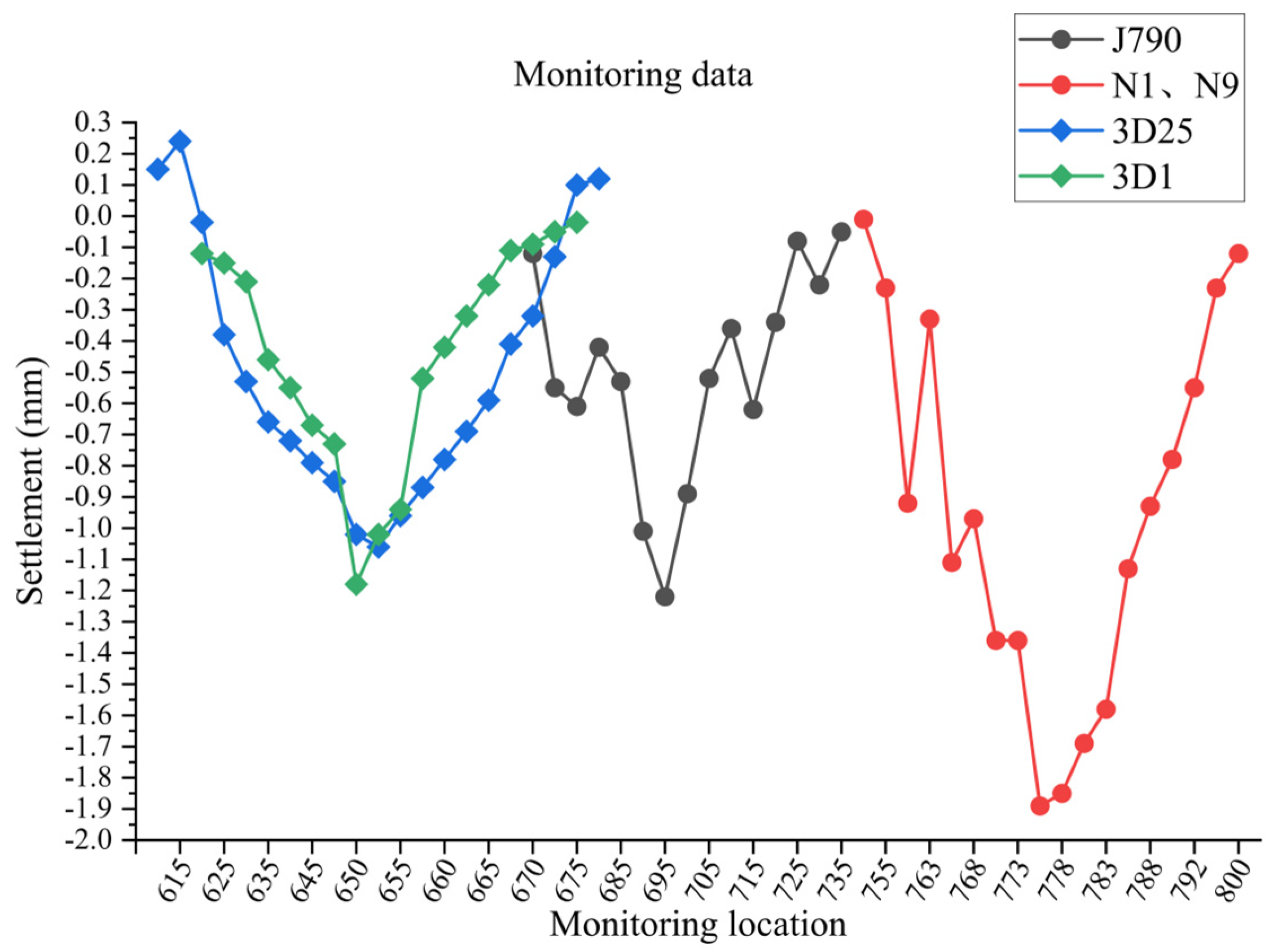
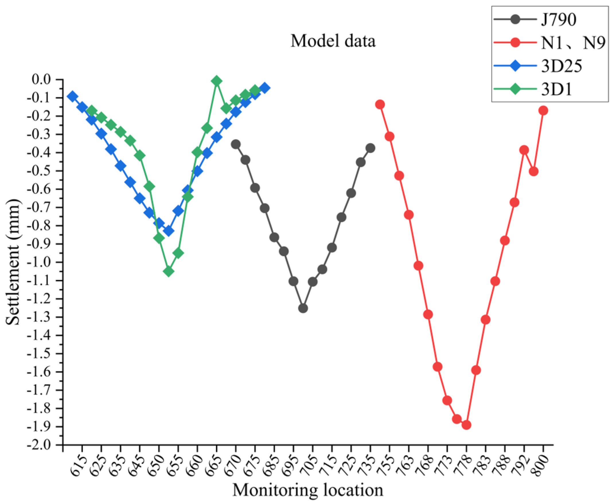
5.3. Overall Analysis

To comprehensively analyze the influences of construction of TCM and HMO pile foundations on the existing metro tunnels, the in situ monitoring data of the TCM and HMO piles are integrated, as shown in Figure 18. The numerical results are integrated in Figure 19. As indicated in Figure 18 and Figure 19, even in the case of TCM pile J790, which is 40 m away from the metro tunnel, both the monitored and numerical maximum settlements of the metro tunnel corresponding to the TCM piles are greater than those corresponding to the HMO piles. This confirms that the degree of influence of TCM pile construction on the existing metro tunnel is greater than that of the HMO pile construction.
Due to the limitations of the field tests, the in situ monitoring data of the test piles only include the settlement of the metro tunnels. Therefore, this paper simulates the in situ test using a three-dimensional finite element numerical simulation, where the missing influencing factors of the in situ test are considered. The numerical simulation not only acquires the settlement of the metro tunnel, but also deeply investigates the Z-axis strain of the metro tunnel. The Z-axis strains of the metro tunnel corresponding to the test piles J790, N1, N9, and 3D25, as well as 3D1, are illustrated in Figure 20, Figure 21, Figure 22 and Figure 23, respectively. It is observed that the Z-axis strain of the metro tunnel located in the area of the test pile locations is larger and decreases with an increase in distance from the test pile locations.

6. Conclusions

By conducting in situ pile tests in the metro protection area and obtaining real-time monitoring data from the metro tunnel, this paper examines the influence of pile foundation construction on neighboring metro tunnels in the context of the Fengqi Chaoming project in Hangzhou, Zhejiang Province, China. Meanwhile, a three-dimensional numerical simulation is carried out using the finite element analysis software Midas GTS. By comparing the numerical simulation results with the in situ monitoring data, the influence of the pile foundation construction in the metro protection area on the existing tunnels is analyzed in depth. The following conclusions can be drawn:
1.
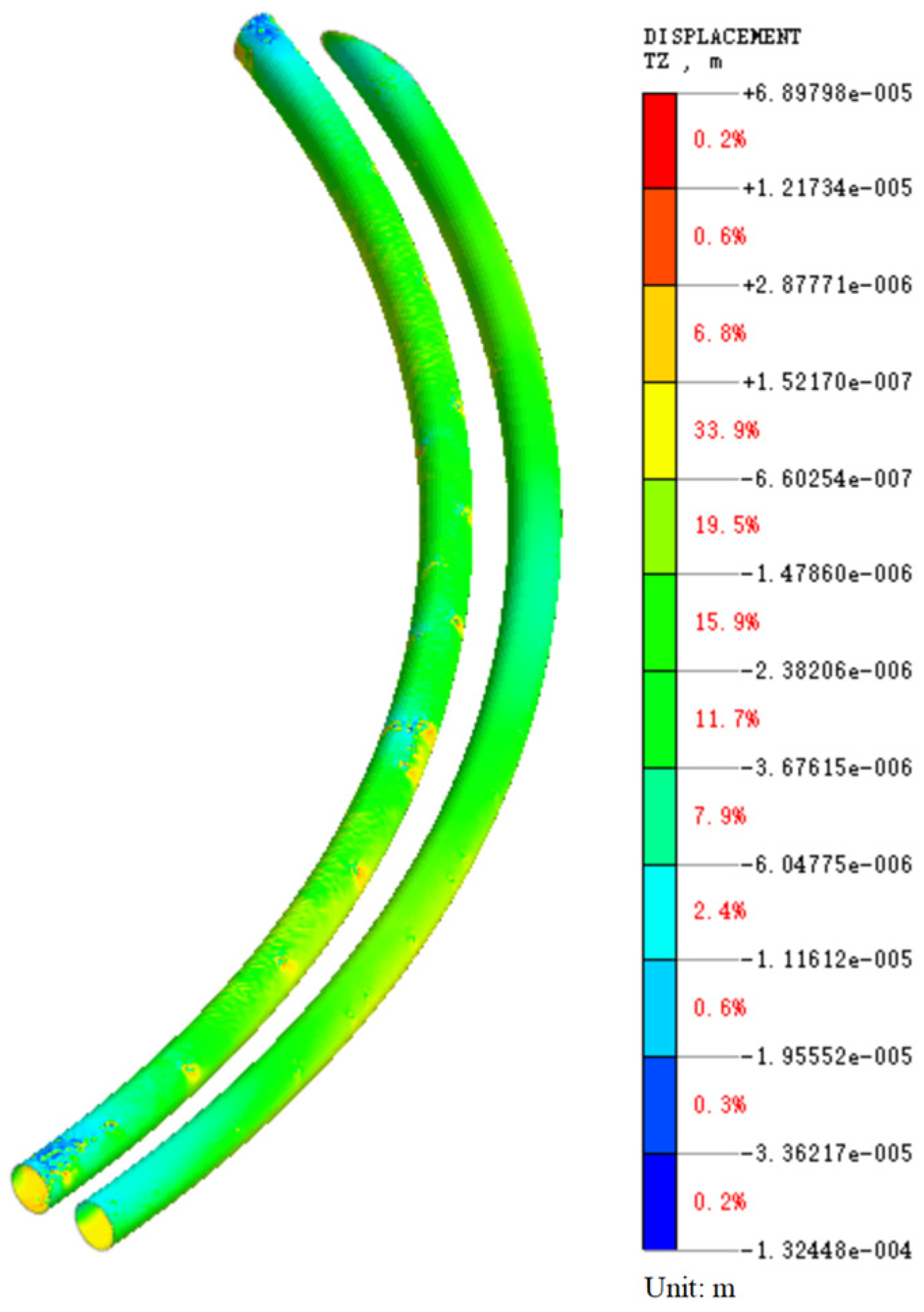
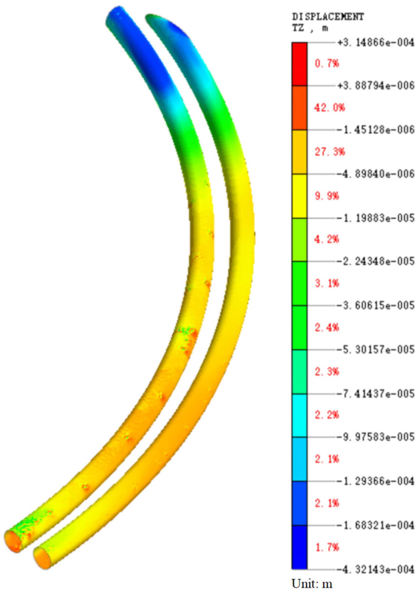
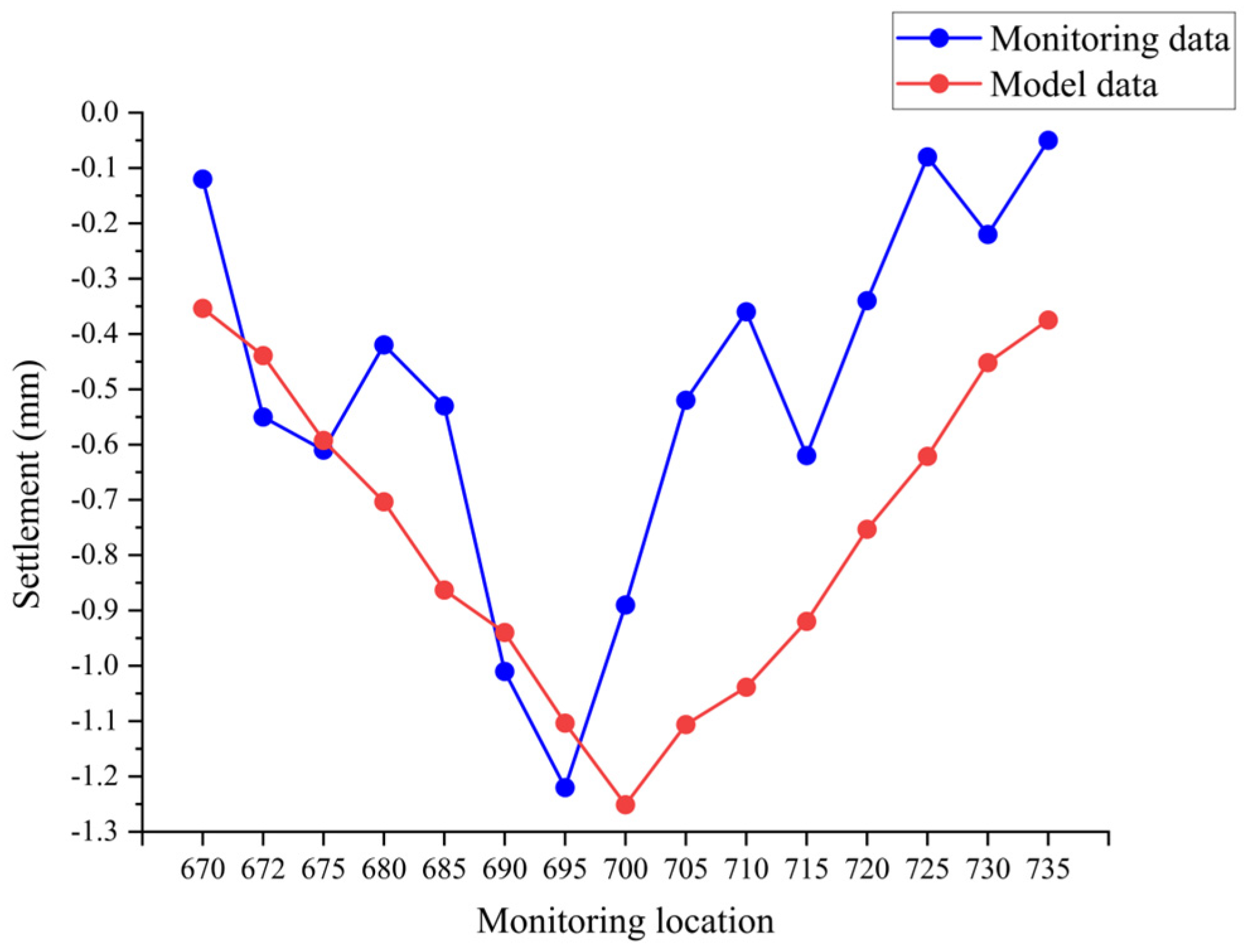
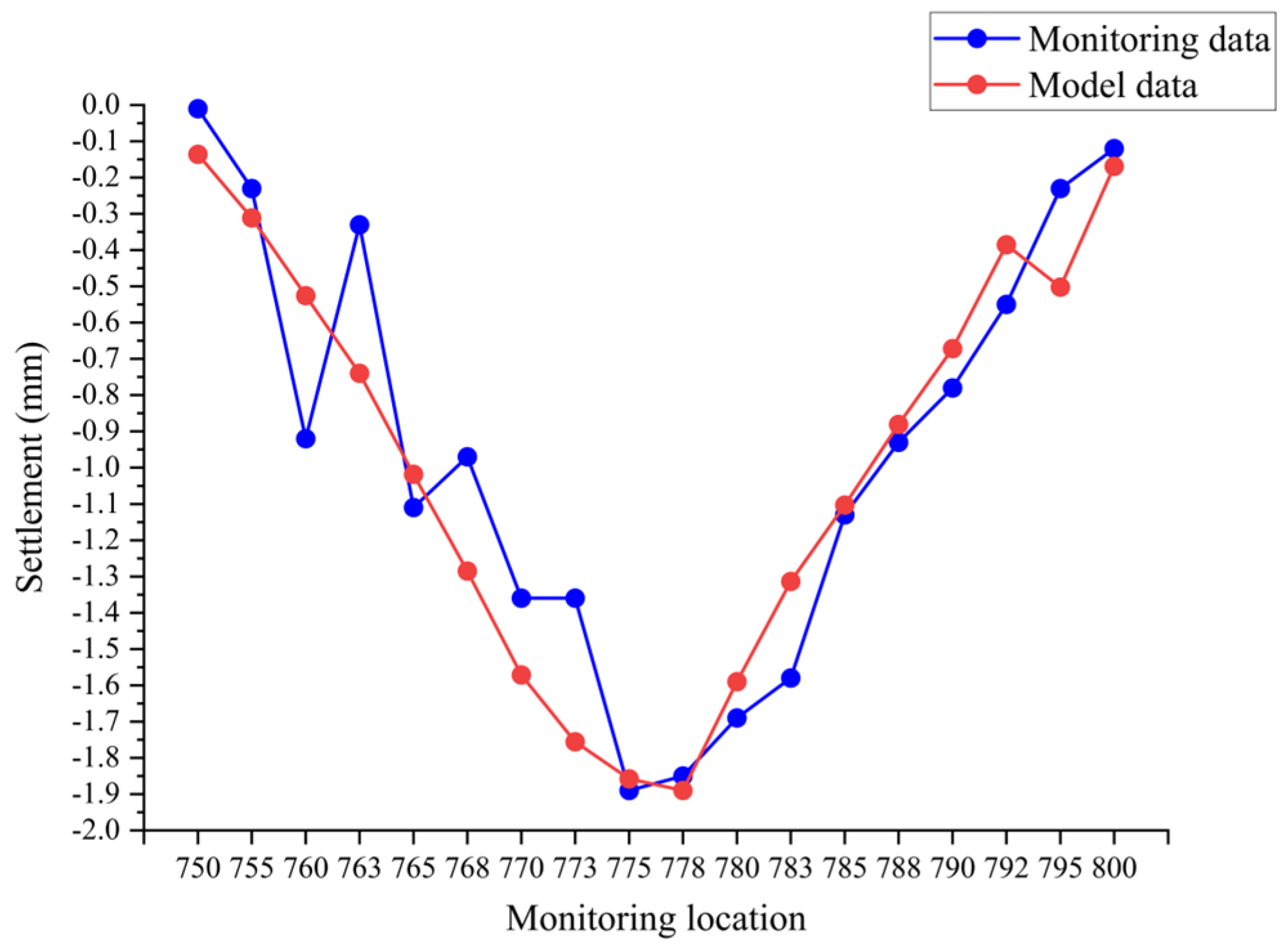
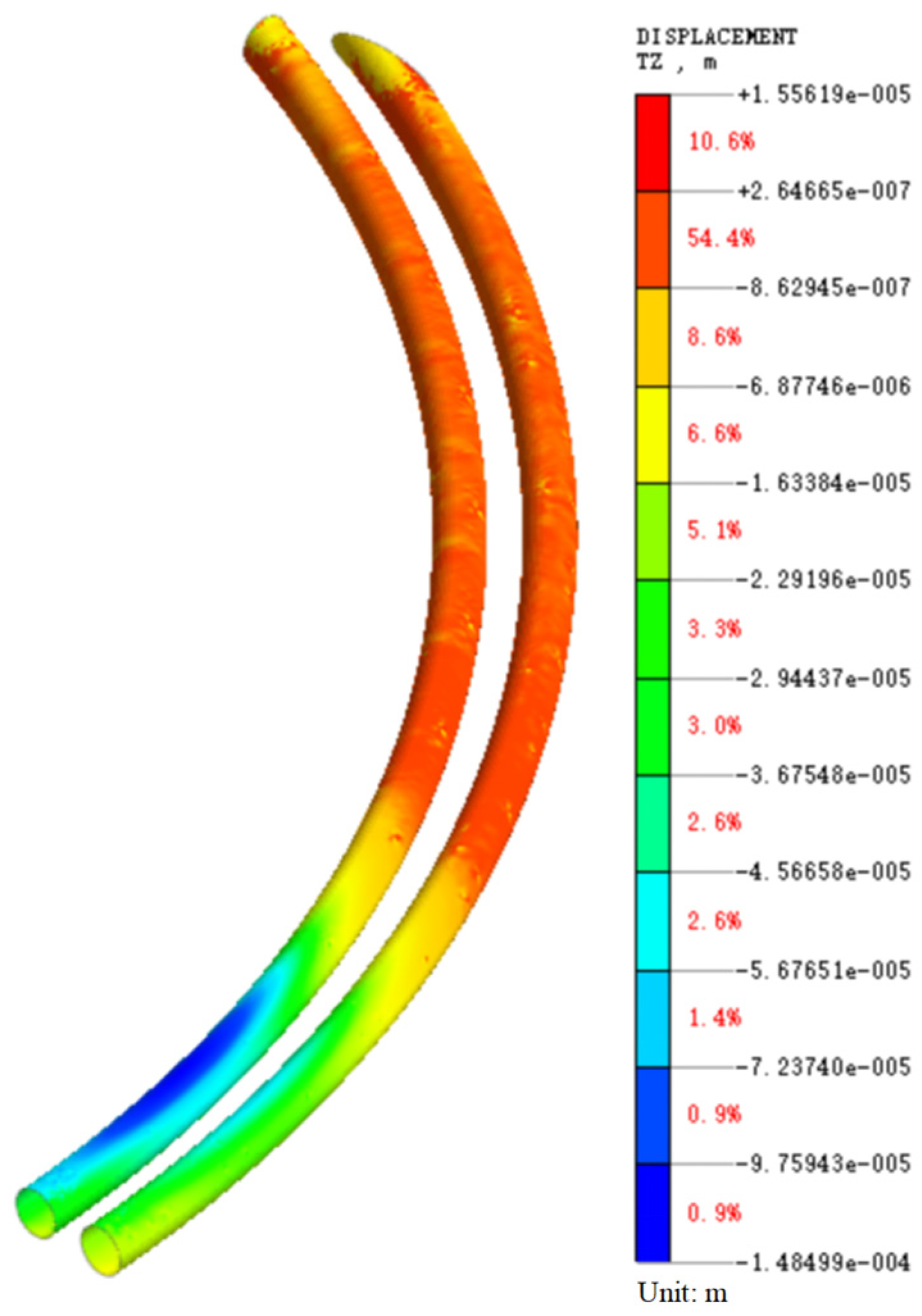
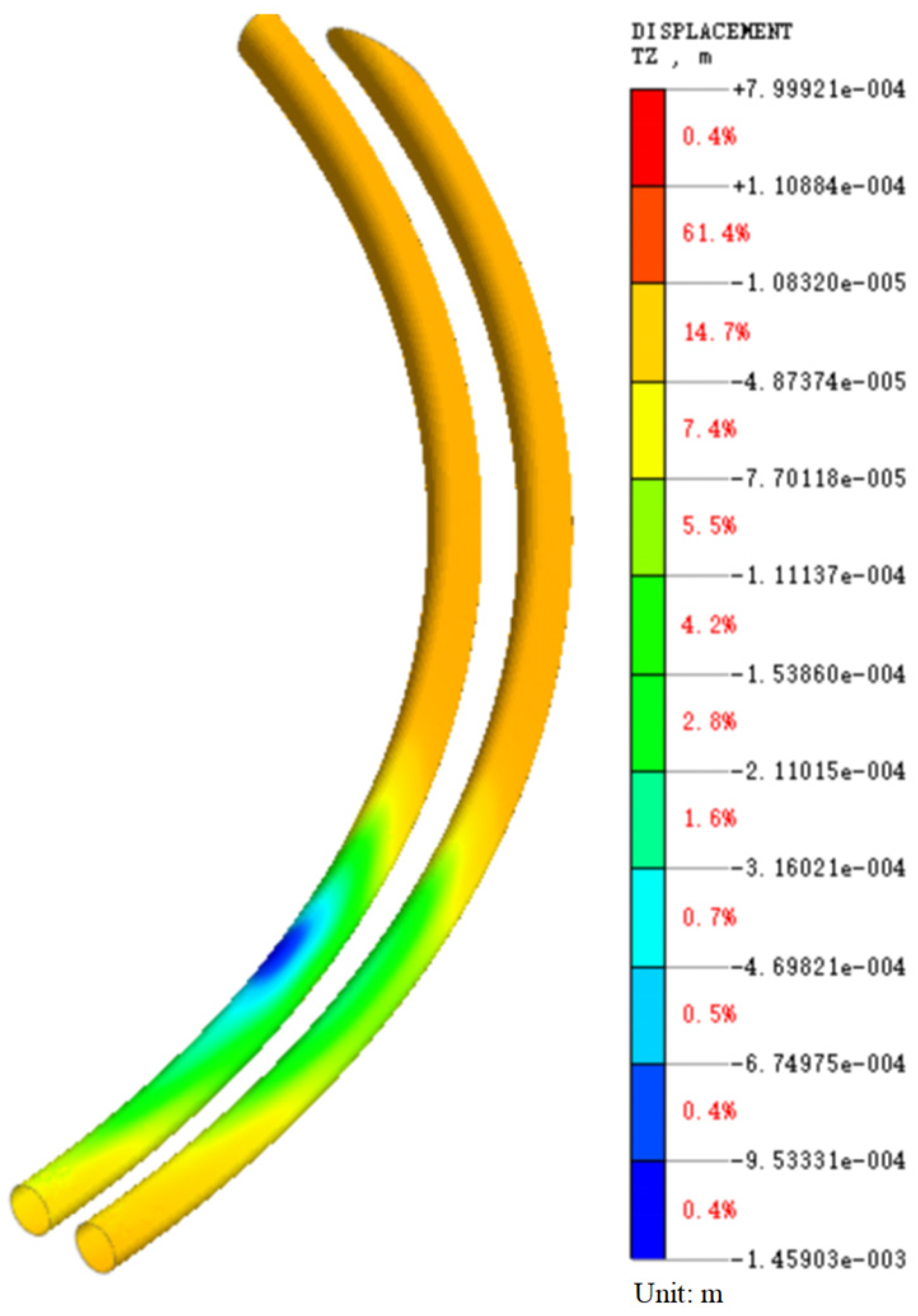
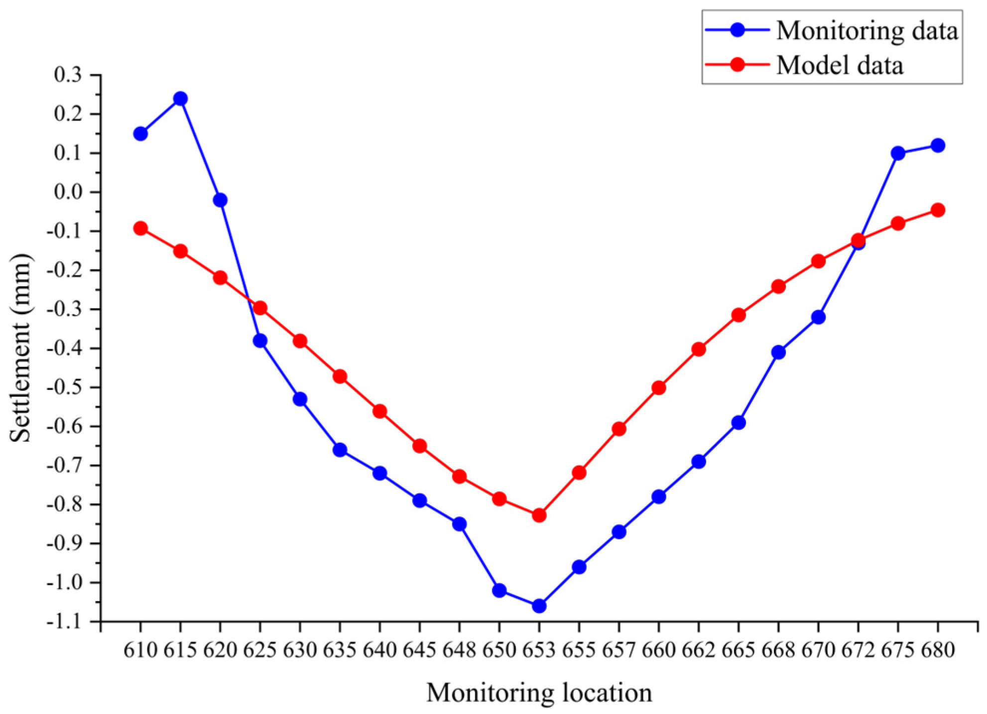
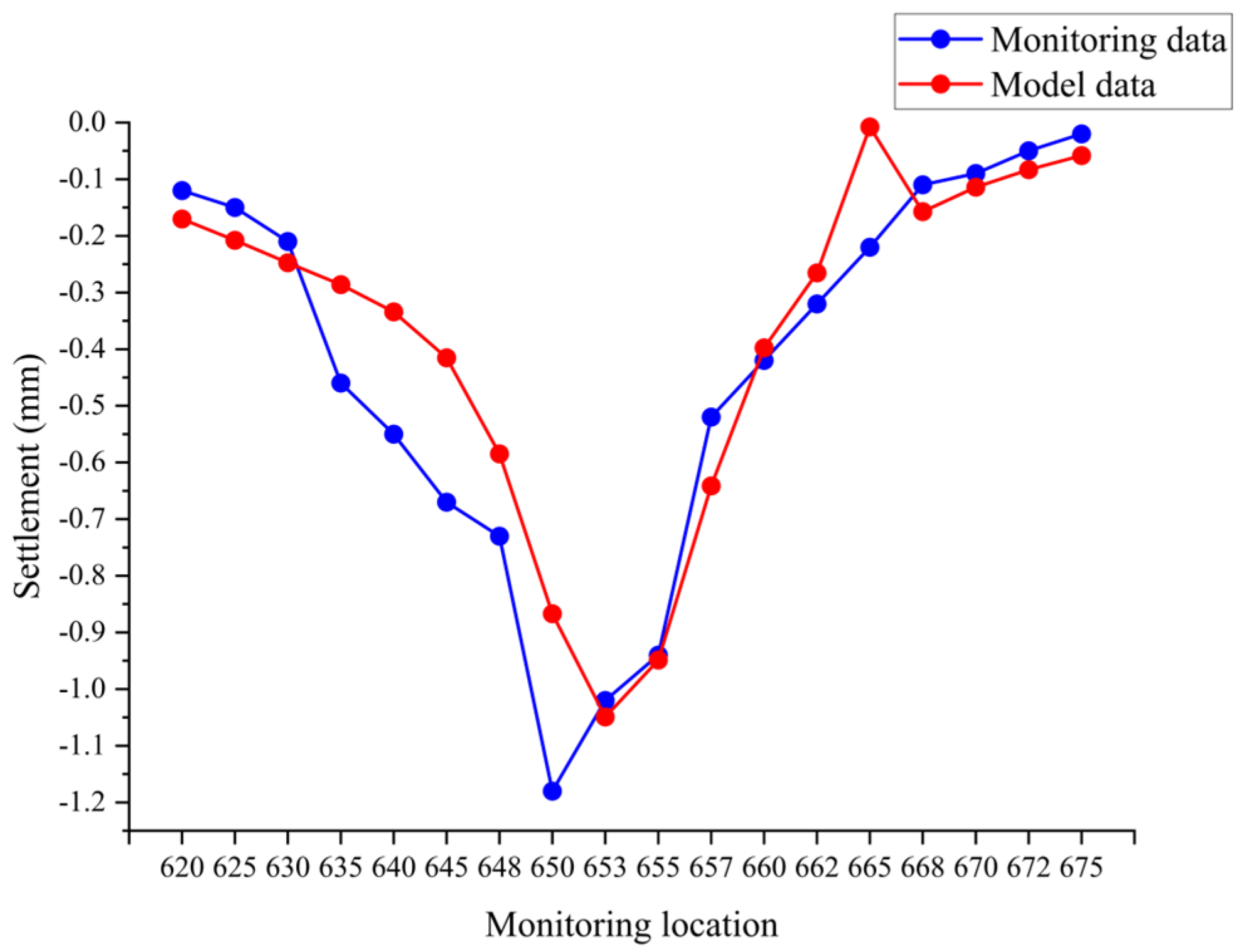
The project on which this study is based is located in the metro protection area, and the pile foundation construction is carried out between the upbound and downbound metro tunnels, so its construction will have a certain influence on the existing metro tunnels. The monitoring data of the in situ pile tests reveal that the maximum settlements of the two groups of TCM piles and the two groups of HMO piles are all within 15 mm of the structural deformation control index of the metro tunnels. The numerical simulation also shows that the maximum settlement of the test piles is within 15 mm. This indicates that the pile foundation construction of the project has less influence on the existing metro tunnels, and the construction process is safe and controllable for the metro shield tunnel.
2.
The monitoring results of both the TCM piles and HMO piles show that the settlement at different metro tunnel monitoring locations caused by the same test pile decreases with increasing distance, and that the maximum degree of influence at different distances from the metro tunnels caused by the same pile type also decreases with increasing distance. An increase in the distance between the pile foundation and the metro tunnel leads to a decrease in the degree of influence.
3.
The maximum settlement corresponding to TCM piles is larger than that corresponding to HMO piles. Different types of pile foundations lead to different degrees of influence, in which the TCM piles have a greater influence on the metro tunnels than the HMO piles.
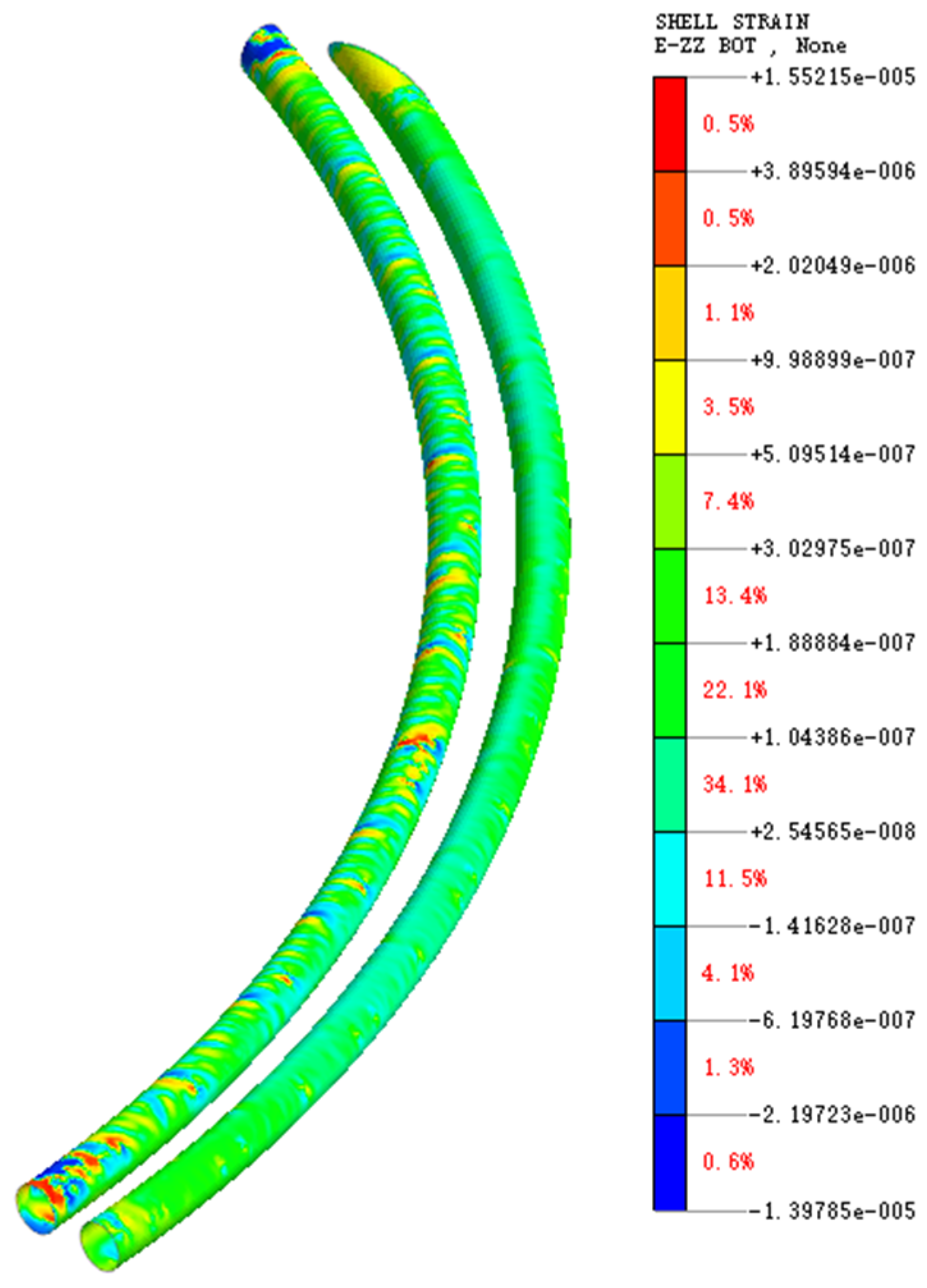
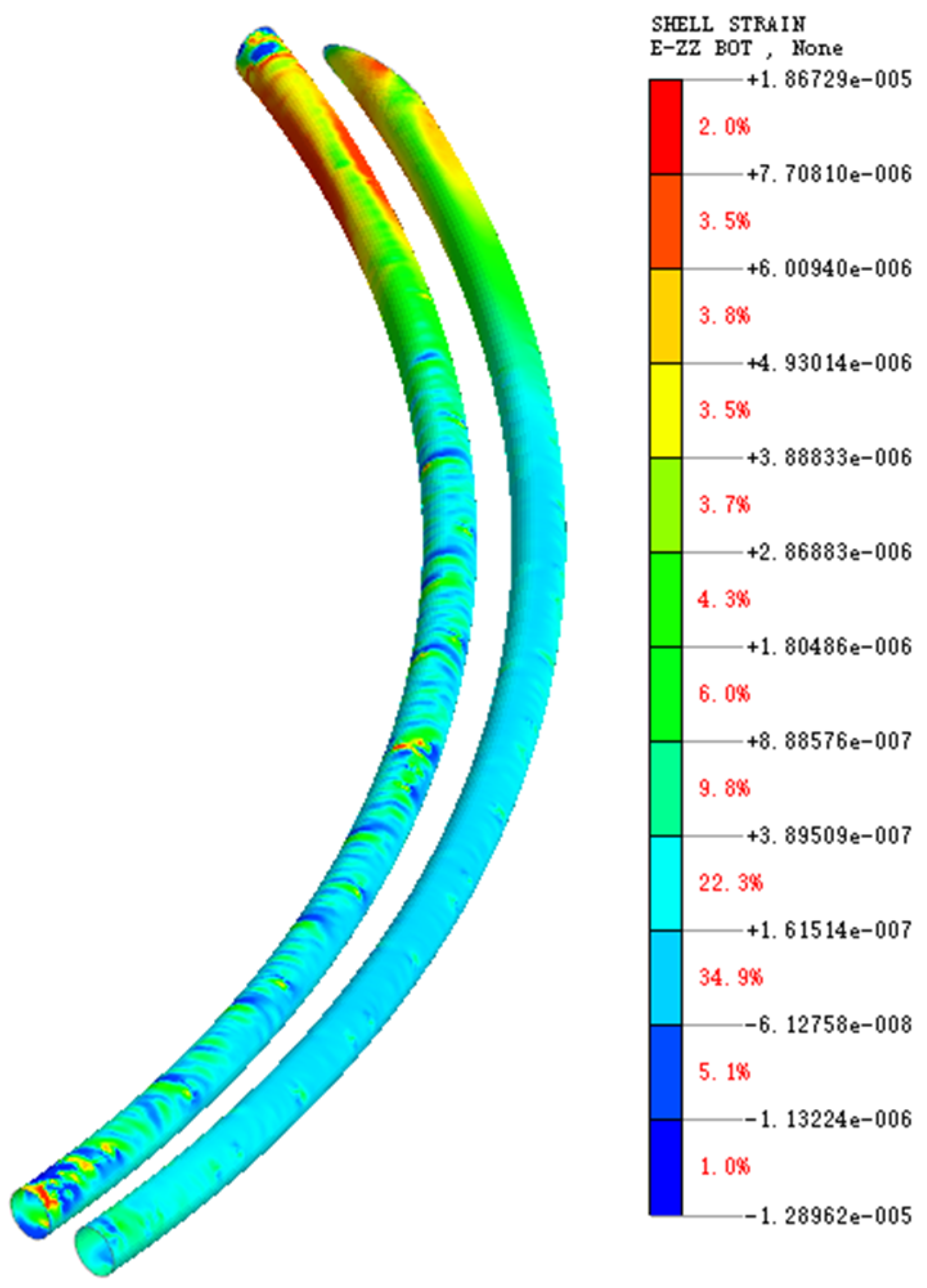
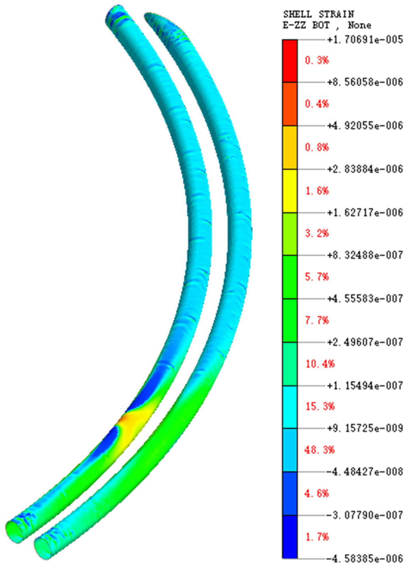
4.
Based on the in situ test, this paper establishes a three-dimensional finite element model to analyze the influences of each test pile on the existing metro tunnels. The reliability of the numerical simulation is verified by comparing the simulation results with the monitoring data of the in situ test piles. Considering the lack of influencing factors in the in situ pile test, the influence of each test pile on the Z-axis strain of the existing metro tunnel is investigated. It is found that the trend of the Z-axis strain is similar to that of the settlement, where the closer the test pile is to the test pile location, the greater the Z-axis strain.
The pile foundation construction of this project is close to the tunnel and the construction is difficult. This paper analyzes the influence of pile foundation construction on the existing tunnels using an in situ pile test and a 3D finite element numerical simulation. The research method and results provide an important reference value for the construction of similar projects in similar areas.

Author Contributions

Conceptualization, S.G.; Data curation, Z.L. and M.C.; Formal analysis, C.X. and Y.X.; Funding acquisition, C.X.; Investigation, W.K.; Methodology, G.L.; Project administration, S.G.; Resources, Z.L.; Software, G.L., C.X. and Y.X. Supervision, Y.X.; Validation, S.G., Z.L., M.C. and Y.X.; Visualization, M.C.; Writing—original draft, G.L. and W.K.; Writing—review & editing, W.K., Z.L. and C.X. All authors have read and agreed to the published version of the manuscript.

Funding

This research was funded by the National Key R&D Program of China, grant number 2023YFC3009400 and the National Natural Science Foundation of China, grant number 52238009.

Data Availability Statement

The data presented in this study are available on request from the corresponding author.

Conflicts of Interest

Authors Gang Lin and Shuaishuai Guo were employed by the company Zhejiang Province Geological & Mineral Engineering Investigation Institute Co., Ltd. The remaining authors declare that the research was conducted in the absence of any commercial or financial relationships that could be construed as a potential conflict of interest.

References

  1. Ren, Y.; Zhou, S.; Jia, J.; Yuan, Q.; Zhou, Z.; Liu, M.; He, H. Construction stability analysis of intersection tunnel in city under CRD method. Front. Earth Sci. 2023, 11, 1264140. [Google Scholar] [CrossRef]
  2. Ng, C.W.; Lee, K.M.; Tang, D.K. Three-dimensional numerical investigations of new Austrian tunnelling method (NATM) twin tunnel interactions. Can. Geotech. J. 2004, 41, 523–539. [Google Scholar] [CrossRef]
  3. Zheng, G.; Zhang, T.; Diao, Y. Mechanism and countermeasures of preceding tunnel distortion induced by succeeding EPBS tunnelling in close proximity. Comput. Geotech. 2015, 66, 53–65. [Google Scholar] [CrossRef]
  4. Chen, R.-P.; Li, J.; Kong, L.-G.; Tang, L.-J. Experimental study on face instability of shield tunnel in sand. Tunn. Undergr. Space Technol. 2013, 33, 12–21. [Google Scholar] [CrossRef]
  5. Yoo, C.; Kim, S.B. Three-dimensional numerical investigation of multifaced tunneling in water-bearing soft ground. Can. Geotech. J. 2008, 45, 1467–1486. [Google Scholar] [CrossRef]
  6. Liang, R.; Xia, T.; Hong, Y.; Yu, F. Effects of above-crossing tunnelling on the existing shield tunnels. Tunn. Undergr. Space Technol. 2016, 58, 159–176. [Google Scholar] [CrossRef]
  7. Islam, S.; Iskander, M. Twin tunnelling induced ground settlements: A review. Tunn. Undergr. Space Technol. 2021, 110, 103614. [Google Scholar] [CrossRef]
  8. Yoo, C. Three dimensional numerical investigation on the effect of bridge construction on existing tunnel. KSCE J. Civ. Eng. 2014, 18, 794–802. [Google Scholar] [CrossRef]
  9. Tao, W.; Le, W.; Nan, C.L. The Influence of Bridge Construction and Operation on Adjacent Nanjing Yangtze River Tunnels. Adv. Mater. Res. 2013, 838–841, 1018–1023. [Google Scholar]
  10. Chen, R.; Meng, F.; Li, Z.; Ye, Y.; Ye, J. Investigation of response of metro tunnels due to adjacent large excavation and protective measures in soft soils. Tunn. Undergr. Space Technol. 2016, 58, 224–235. [Google Scholar] [CrossRef]
  11. Sharma, J.; Hefny, A.; Zhao, J.; Chan, C. Effect of large excavation on deformation of adjacent MRT tunnels. Tunn. Undergr. Space Technol. 2001, 16, 93–98. [Google Scholar] [CrossRef]
  12. Doležalová, M. Tunnel complex unloaded by a deep excavation. Comput. Geotech. 2001, 28, 469–493. [Google Scholar] [CrossRef]
  13. Meguid, M.A.; Rowe, R.K.; Lo, K.Y. 3D effects of surface construction over existing subway tunnels. Int. J. Geomech. 2002, 2, 447–469. [Google Scholar] [CrossRef]
  14. Liang, R.; Xia, T.; Huang, M.; Lin, C. Simplified analytical method for evaluating the effects of adjacent excavation on shield tunnel considering the shearing effect. Comput. Geotech. 2017, 81, 167–187. [Google Scholar] [CrossRef]
  15. Veeraraghavan, S. Semi-analytical solution for the 3D response of tunnels subjected to seismic waves. Tunn. Undergr. Space Technol. 2024, 152, 105925. [Google Scholar] [CrossRef]
  16. Xu, C.; Chen, Q.; Luo, W.; Liang, L. Evaluation of permanent settlement in Hangzhou Qingchun road crossing-river tunnel under traffic loading. Int. J. Geomech. 2019, 19, 06018037. [Google Scholar] [CrossRef]
  17. Lee, Y.J.; Bassett, R.H. A model test and numerical investigation on the shear deformation patterns of deep wall–soil–tunnel interaction. Can. Geotech. J. 2006, 43, 1306–1323. [Google Scholar] [CrossRef]
  18. Franza, A.; Marshall, A.M.; Haji, T.; Abdelatif, A.O.; Carbonari, S.; Morici, M. A simplified elastic analysis of tunnel-piled structure interaction. Tunn. Undergr. Space Technol. 2017, 61, 104–121. [Google Scholar] [CrossRef]
  19. Schroeder, F.C. The Influence of Bored Piles on Existing Tunnels. Ph.D. Thesis, Imperial College London, London, UK, 2003. [Google Scholar]
  20. Arora, K.; Gutierrez, M. Viscous-elastic-plastic response of tunnels in squeezing ground conditions: Analytical modeling and experimental validation. Int. J. Rock Mech. Min. Sci. 2021, 146, 104888. [Google Scholar] [CrossRef]
  21. Liu, H.; Small, J.; Carter, J.; Williams, D. Effects of tunnelling on existing support systems of perpendicularly crossing tunnels. Comput. Geotech. 2009, 36, 880–894. [Google Scholar] [CrossRef]
  22. Saleh Asheghabadi, M.; Rahgozar, M.A. Finite element seismic analysis of soil–tunnel interactions in clay soils. Iran. J. Sci. Technol. Trans. Civ. Eng. 2019, 43, 835–849. [Google Scholar] [CrossRef]
  23. Liu, H.; Small, J.; Carter, J. Full 3D modelling for effects of tunnelling on existing support systems in the Sydney region. Tunn. Undergr. Space Technol. 2008, 23, 399–420. [Google Scholar] [CrossRef]
  24. Yoo, C. Interaction between tunneling and groundwater—Numerical investigation using three dimensional stress–pore pressure coupled analysis. J. Geotech. Geoenviron. Eng. 2005, 131, 240–250. [Google Scholar] [CrossRef]
  25. Shi, J.; Ng, C.W.W.; Chen, Y. Three-dimensional numerical parametric study of the influence of basement excavation on existing tunnel. Comput. Geotech. 2015, 63, 146–158. [Google Scholar] [CrossRef]
  26. Li, T.; Yang, M.; Chen, X. A Simplified Analytical Method for the Deformation of Pile Foundations Induced by Adjacent Excavation in Soft Clay. Buildings 2023, 13, 1919. [Google Scholar] [CrossRef]
  27. Zhang, Z.; Zhang, M.; Jiang, Y.; Bai, Q.; Zhao, Q. Analytical prediction for ground movements and liner internal forces induced by shallow tunnels considering non-uniform convergence pattern and ground-liner interaction mechanism. Soils Found. 2017, 57, 211–226. [Google Scholar] [CrossRef]
  28. Wei, G.; Zhang, X. Calculation of rotation and shearing dislocation deformation of underlying shield tunnels due to foundation pit excavation. J. Cent. South Univ. 2019, 50, 2273–2284. [Google Scholar]
  29. Zhou, P.; Liu, H.; Zhou, H.; Xu, C.; Cui, J.; Ding, X. Experimental study on the development of surrounding soil stress during XCC pile installation in sand. Acta Geotech. 2023, 19, 4017–4035. [Google Scholar] [CrossRef]
  30. Zhou, P.; Liu, H.; Zhou, H.; Cao, G.; Ding, X. A simplified analysis approach for the effect of the installation of adjacent XCC pile on the existing single XCC pile in undrained clay. Acta Geotech. 2022, 17, 5499–5519. [Google Scholar] [CrossRef]
  31. Zhou, P.; Zhou, H.; Liu, H.; Li, X.; Ding, X.; Wang, Z. Analysis of lateral response of existing single pile caused by penetration of adjacent pile in undrained clay. Comput. Geotech. 2020, 126, 103736. [Google Scholar] [CrossRef]
  32. Zhou, P.; Liu, H.; Zhou, H.; Cao, G.; Ding, X. A lateral soil resistance model for XCC pile in soft clay considering the effect of the geometry of cross section. Acta Geotech. 2022, 17, 4681–4697. [Google Scholar] [CrossRef]
  33. Alver, O.; Eseller-Bayat, E.E. A new p-y model for soil-pile interaction analyses in cohesionless soils under monotonic loading. Soils Found. 2024, 64, 101441. [Google Scholar] [CrossRef]
  34. Sakellariadis, L.; Anastasopoulos, I. Analytical 3D failure envelopes for RC pile groups under combined loading: A generalised design approach. Soil Dyn. Earthq. Eng. 2024, 181, 108570. [Google Scholar] [CrossRef]
  35. Lee, Y.J.; Bassett, R.H. Influence zones for 2D pile–soil-tunnelling interaction based on model test and numerical analysis. Tunn. Undergr. Space Technol. 2007, 22, 325–342. [Google Scholar] [CrossRef]
  36. Franza, A.; Marshall, A.M. Centrifuge modeling study of the response of piled structures to tunneling. J. Geotech. Geoenviron. Eng. 2018, 144, 04017109. [Google Scholar] [CrossRef]
  37. Zhang, Z.; Zhang, C.; Jiang, K.; Wang, Z.; Jiang, Y.; Zhao, Q.; Lu, M. Analytical prediction for tunnel-soil-pile interaction mechanics based on Kerr foundation model. KSCE J. Civ. Eng. 2019, 23, 2756–2771. [Google Scholar] [CrossRef]
  38. Zhang, Z.; Huang, M.; Xu, C.; Jiang, Y.; Wang, W. Simplified solution for tunnel-soil-pile interaction in Pasternak’s foundation model. Tunn. Undergr. Space Technol. 2018, 78, 146–158. [Google Scholar] [CrossRef]
  39. Dias, T.G.S.; Bezuijen, A. Data analysis of pile tunnel interaction. J. Geotech. Geoenviron. Eng. 2015, 141, 04015051. [Google Scholar] [CrossRef]
  40. Marshall, A.M.; Haji, T. An analytical study of tunnel–pile interaction. Tunn. Undergr. Space Technol. 2015, 45, 43–51. [Google Scholar] [CrossRef]
  41. Cheng, C.Y.; Dasari, G.R.; Chow, Y.K.; Leung, C.F. Finite element analysis of tunnel–soil–pile interaction using displacement controlled model. Tunn. Undergr. Space Technol. 2007, 22, 450–466. [Google Scholar] [CrossRef]
  42. Schroeder, F.C.; Potts, D.M.; Addenbrooke, T.I. The influence of pile group loading on existing tunnels. Geotechnique 2004, 54, 351–362. [Google Scholar] [CrossRef]
  43. Lin, Z.; Jiang, Y.; Xiong, Y.; Xu, C.; Guo, Y.; Wang, C.; Fang, T. Analytical solution for displacement-dependent active earth pressure considering the stiffness of cantilever retaining structure in cohesionless soil. Comput. Geotech. 2024, 170, 106258. [Google Scholar] [CrossRef]
  44. Lueprasert, P.; Jongpradist, P.; Jongpradist, P.; Schweiger, H.F. Structural responses of a tunnel lining due to an adjacent loaded pile. Int. J. Civ. Eng. 2023, 21, 1027–1043. [Google Scholar] [CrossRef]
  45. Lueprasert, P.; Jongpradist, P.; Jongpradist, P.; Suwansawat, S. Numerical investigation of tunnel deformation due to adjacent loaded pile and pile-soil-tunnel interaction. Tunn. Undergr. Space Technol. 2017, 70, 166–181. [Google Scholar] [CrossRef]
  46. Lueprasert, P.; Jongpradist, P.; Charoenpak, K.; Chaipanna, P.; Suwansawat, S. Three dimensional finite element analysis for preliminary establishment of tunnel influence zone subject to pile loading. Maejo Int. J. Sci. Technol. 2015, 9, 209–223. [Google Scholar]
  47. Mroueh, H.; Shahrour, I. Three-dimensional finite element analysis of the interaction between tunneling and pile foundations. Int. J. Numer. Anal. Methods Geomech. 2002, 26, 217–230. [Google Scholar] [CrossRef]
Figure 1. Plan of the metro tunnels in the construction area of the Fengqi Chaoming project.
Buildings 14 02280 g001
Figure 2. Pile locations for TCM pile test and layout of monitoring points.
Buildings 14 02280 g002
Figure 3. Pile locations for the HMO pile test and layout of monitoring points.
Buildings 14 02280 g003
Figure 4. Three-dimensional finite element model of TCM pile.
Buildings 14 02280 g004
Figure 5. Three-dimensional finite element model of HMO pile.
Buildings 14 02280 g005
Figure 6. Settlement of metro tunnel during construction of test pile J790.
Buildings 14 02280 g006
Figure 7. Settlement of metro tunnel during construction of test piles N1 and N9.
Buildings 14 02280 g007
Figure 8. Data for test pile J790.
Buildings 14 02280 g008
Figure 9. Data for test piles N1 and N9.
Buildings 14 02280 g009
Figure 10. Monitoring results of TCM pile.
Buildings 14 02280 g010
Figure 11. Numerical results of TCM pile.
Buildings 14 02280 g011
Figure 12. Settlement of metro tunnel during construction of test pile 3D25.
Buildings 14 02280 g012
Figure 13. Settlement of metro tunnel during construction of test pile 3D1.
Buildings 14 02280 g013
Figure 14. Data for test pile 3D25.
Buildings 14 02280 g014
Figure 15. Data for test pile 3D1.
Buildings 14 02280 g015
Figure 16. Monitoring results of HMO pile.
Buildings 14 02280 g016
Figure 17. Numerical results of HMO pile.
Buildings 14 02280 g017
Figure 18. In situ monitoring data of the test piles.
Buildings 14 02280 g018
Figure 19. Numerical results of the test piles.
Buildings 14 02280 g019
Figure 20. Plot of Z-axis strain data of metro tunnel for test pile J790.
Buildings 14 02280 g020
Figure 21. Plot of Z-axis strain data of metro tunnel for test piles N1 and N9.
Buildings 14 02280 g021
Figure 22. Plot of Z-axis strain data of metro tunnel for test pile 3D25.
Buildings 14 02280 g022
Figure 23. Plot of Z-axis strain data of metro tunnel for test pile 3D1.
Buildings 14 02280 g023
Table 1. Control indexes of structural deformation in metro tunnels.
Monitoring ProjectsControl ValueNote
Tunnel StructureShield tunnel uplift and subsidence≤15 mmMonitoring value ≥ daily monitoring indicators or monitoring value ≥ 1/2 of the total deformation control volume need to be alarmed, and shall not affect its safe and normal use.
Shield Tunnel Horizontal Displacement≤10 mm
Shield tunnel tube sheet lateral deformation≤5 mm
Maximum Horizontal Displacement of Enclosure Structure<20 mm
Table 2. Soil parameters.
Soil Layer NameGravity
(kN/m3)
Cohesion
(kPa)
Angle of Internal Friction
(°)
Compressed Modulus
ES MPa
Poisson’s Ratio
Miscellaneous fillings18.012.012.04.00.2
Sandy chalk18.14.023.510.00.2
Sandy chalk with silt19.23.029.59.00.2
Silty chalky clay18.012.09.53.00.2
Sandy chalk19.06.018.05.80.2
Sandy chalk18.518.011.94.00.2
Strongly weathered muddy siltstone20.0 0.3
Table 3. Parameters of TCM piles.
StakeBorehole Diameter
(mm)
Concrete GradeDrilling Dept
(m)
Construction DateDistance to Subway
(m)
Influence Ring Number
J790850@600C4020.57–2040.0Up line
670–730
N1850@600C4015.57–2220.3Down line 750–800
N9850@600C4015.57–228.4Down line 760–800
Table 4. Parameters of tested HMO piles.
StakeBorehole Diameter
(mm)
Concrete GradeDrilling Dept
(m)
Construction DateDistance to Subway
(m)
Influence Ring Number
3D251000C4025.07–2212.0Down line
610–670
3D11000C4025.07–254.9Down line 620–670
Table 5. Parameters of soil mode.
Soil Layer NameSoil Thickness
(m)
E50
(MPa)
Eoed
(MPa)
Eur
(MPa)
Gravity (kN/m3)Cohesion
(kPa)
Angle of Internal Friction
(°)
Poisson’s Ratio
Miscellaneous fillings1.54000400021,00018.012.012.00.2
Sandy chalk8.010,00010,00045,00018.14.023.50.2
Sandy chalk with silt4.59000900040,00019.23.029.50.2
Silty chalky clay11.53000300020,00018.012.09.50.2
Sandy chalk8.05800580040,00019.06.0180.2
Sandy chalk3.54000400035,00018.518.011.90.2
Strongly weathered Muddy siltstone13.0 20.0 0.3
Table 6. Parameters of concrete model for pile foundation.
StakeBorehole Diameter
(mm)
Concrete GradeDrilling Dept
(m)
Modulus of Elasticity
ES MPa
Gravity
(kN/m3)
Poisson’s Ratio
J790850@600C4020.53.25 × 10424.390.2
N1850@600C4015.53.25 × 10424.390.2
N9850@600C4015.53.25 × 10424.390.2
3D251000C4025.03.25 × 10424.390.2
3D11000C4025.03.25 × 10424.390.2
Table 7. Parameters of metro tunnel lining model.
Concrete GradeModulus of Elasticity
ES MPa
Gravity
(kN/m3)
Poisson’s RatioTunnel Depth
(m)
C503.55 × 10425.00.224.0
Disclaimer/Publisher’s Note: The statements, opinions and data contained in all publications are solely those of the individual author(s) and contributor(s) and not of MDPI and/or the editor(s). MDPI and/or the editor(s) disclaim responsibility for any injury to people or property resulting from any ideas, methods, instructions or products referred to in the content.

