Abstract
Alkali-activated materials (AAMs) are favoured for their low carbon emissions, excellent mechanical properties, and excellent chemical resistance. In this paper, ternary alkali-activated cementitious materials were prepared from slag, steel slag, and lithium slag to investigate their strength and resistance to sulphate attack. A series of experiments were conducted using a variety of material combinations, alkali activator combinations, water–binder ratios, and exposure environments. These experiments employed both macro and micro comparative analyses. The hydration reaction products, physical phase composition, and microstructure of the ground granulated furnace slag, lithium slag, and steel slag (GLS) ternary AAMs were analysed using x-ray diffraction (XRD), Fourier-transform infrared spectroscopy (FTIR), scanning electron microscopy (SEM), and energy dispersive spectroscopy (EDS). It was experimentally demonstrated that the GLS ternary AAMs had excellent compressive strength, good resistance to sodium sulphate erosion, and that resistance to magnesium sulphate erosion decreased with time. This study contributes to the advancement of knowledge regarding the utilisation of lithium slag and steel slag, and offers new insights into the field of alkali-activated cementitious materials and their resistance to sulphate erosion.
1. Introduction
Portland cement is one of the most widely used cementitious materials in the construction industry, with annual global production reaching 4.3 billion tons by 2021. Its production process is responsible for around 8% of global greenhouse gas emissions, and the high energy consumption of the production process is also a concern [1,2]. To address this challenge, researchers are actively looking for alternatives, and alkali-activated materials (AAMs) are a high-profile option, favoured for their low carbon emissions, excellent mechanical properties, and excellent chemical resistance [3,4,5,6]. Common solid wastes used for the preparation of AAMs are ground granulated blast furnace slag (GGBFS), fly ash (FA), silica fume (SF), steel slag (SS), and lithium slag (LS). Nevertheless, the low early reactivity of SS and LS restricts their widespread utilization, necessitating their combination with other solid wastes. In contrast, extensive research has been conducted on the utilization of slag in AAMs production [7,8], demonstrating its positive influence on early strength development and microstructural evolution [9,10].
SS is an industrial solid waste produced in the steel-making process, and SS emissions account for about 15% of crude steel [11], but its comprehensive utilization rate is only about 30%. The main chemical compositions of SS are CaO, SiO2, Fe2O3, Al2O3, and MgO, and its composition is similar to that of cement, but the content of CaO and SiO2 is lower than that of silicate cement [12]. The mineral constituent phases C2S and C3S in steel slag have a certain activity, which can be hydrated to generate hydrated calcium silicate and calcium hydroxide [13]. The weak water absorption of SS can improve the fluidity of composite cementitious materials. However, due to the special physicochemical properties in SS and the differences brought about by different smelting processes and treatments, SS has problems such as low early activity and long coagulation time, which lead to the limitation of the utilisation of SS [14].
LS is a residue discharged after leaching, filtration, and washing during the production of lithium salts from lithium ores [15]. LS has a high content of amorphous SiO2 and Al2O3, which can be used as a preparation for AAMs [16,17]. The content of reactive silica-aluminate phases in LS is relatively low, and a large amount of LS is detrimental to the early strength of the material [18]. LS contains a high amount of SO42− and has to be used in conjunction with other gelling, cementitious materials with low SO3 content. LS has a porous structure, its specific surface area is large, and adsorbs a large amount of water and water-reducing agent. In order to make lithium slag achieve a certain degree of plasticity, the amount of water or water-reducing agent must be increased, which is not conducive to cost control.
Sulphate attack represents a significant durability challenge for cementitious materials. Over the past few decades, numerous structural elements worldwide have experienced severe deterioration as a consequence of sulphate attack [19,20,21]. Although this is not a new problem, our understanding of sulphate attack is still confusing, and there are still no clear conclusions about its attack mechanism [22,23]. Sulphate erosion is a complex physico–chemical process. In cementitious materials, sulphate erosion damage manifests in a series of chemical and physical forms. These include Ettringite swelling damage, Gypsum swelling damage, thaumasite swelling damage, as well as Na2SO4 crystallisation damage [24,25]. (1) Physical erosion: Na2SO4 crystallisationn mainly occurs in locations with frequent alternation between wet and dry periods. The resulting expansion pressure on the pore wall from Na2SO4 crystallisation or crystalline transformation can lead to cracking and damage of the material when the magnitude of this stress exceeds the tensile strength of the cementitious material [26]. (2) Chemical erosion: Ettringite expansion damage is caused by SO42− first generating Ca2SO4 with Ca(OH)2, a hydration product in the cement, and then Ca2SO4 generating Aft with aluminates in the cement, resulting in a 2.2-fold expansion of the matrix volume, which in turn causes damage through expansion [27]. When the SO42− concentration is greater than a certain value, and at the same time the capillary pores of the cement are filled with saturated Ca(OH)2 solution, not only is ettringite generated but gypsum crystals are also precipitated, which contributes to the volume increase by a factor of 1.24, leading to matrix destruction [25]. Thaumasite is formed from Ca(OH)2, CaCO3, silicates, and gypsum at low temperatures, which causes the surface of the cementitious material to become limp and reduce its strength [28].
AAMs are chemically more stable than ordinary Portland cement. Many researchers have investigated the sulphate-induced degradation of AAMs [29,30,31,32]. While numerous studies have focused on the macroscopic results of sulphate erosion [33,34], fewer have delved into the qualitative and quantitative analyses of the erosion products and the microscopic erosion mechanisms of AAMs after sulphate damage.This paper makes three original contributions to the field. Firstly, the study focuses on alkali-activated materials comprising three types of materials, which is a less common focus in previous studies, which have primarily concentrated on slag-based AAMs. Secondly, the research considers a variety of materials and environmental exposure conditions in its mix ratios. Thirdly, the macroscopic degradation mechanisms are elucidated through microscopic analysis. This study aims to fill these gaps to better understand the performance of AAMs in practical applications.
In this study, GGBFS, LS, and SS were used to produce ground granulated furnace slag, lithium slag, and steel slag (GLS) ternary AAMS with varying modulus of alkali activator (SiO2/Na2O molar ratio), alkali activator content (based on Na2O equivalent), water–binder (w/b) ratios, and mineral mixing ratios as the variables. The specimens were immersed in a sulphate solution after maintenance to investigate the deterioration mechanism of GLS ternary AAMs under sulphate erosion. The study aimed to reveal the deterioration process of GLS ternary AAMs from both macroscopic and microscopic perspectives.
2. Experimental Methodology
2.1. Materials
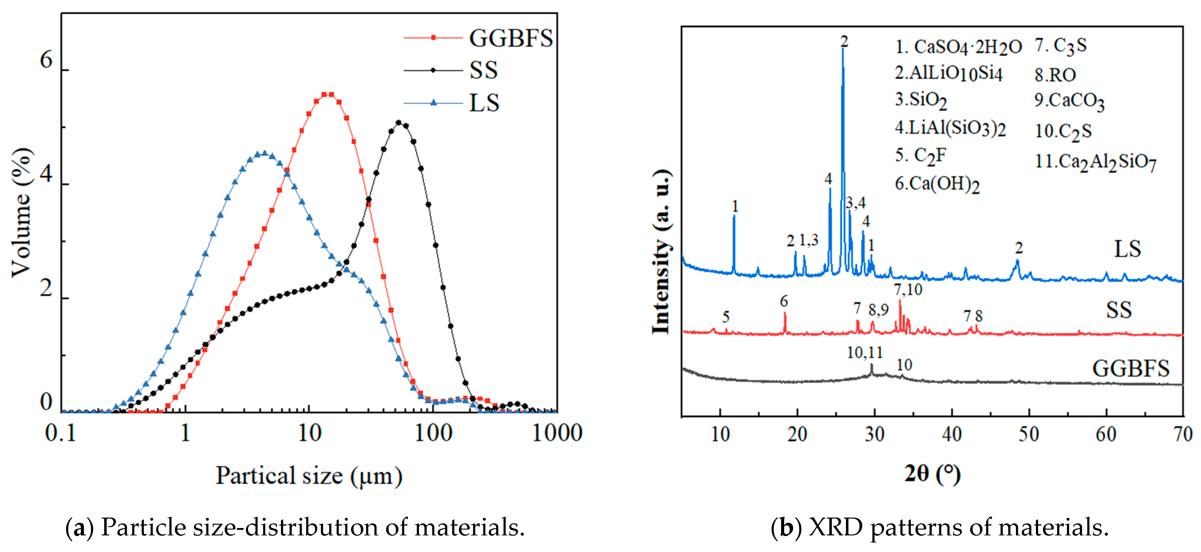
The raw materials used to develop GLS ternary AAMS precursors were GGBFS, LS, and SS. GGBFS (S105), with a milky white appearance, was obtained from a building materials company (Zhengzhou, Henan province, China). SS was provided by Hebei Jingye Steel Plant (Shijiazhuang, Hebei Province, China). LS was provided by Guangxi Tianyuan New Energy Material Co. Ltd. (Beihai, Guangxi Province, China). The main chemical composition of the raw materials is shown in Table 1, and the particle size-distribution and mineral phase-composition are shown in Figure 1. The main crystalline phase of GGBFS was calcium silicate, calcium–aluminium yellow feldspar, and calcite. The main crystalline phase of LS was lithium pyroxene, RO phase, tricalcium silicate, and dicalcium silicate. The main crystalline phase of SS was composed of minerals including calcium carbonate, calcium hydroxide, tricalcium silicate, and dicalcium silicate. The LS and SS were dried in a drying oven (105 °C ± 5 °C) until the moisture content was less than 1%. Subsequently, this was ground in an XQM-4 vertical planetary ball mill at 300 r/min for 15 min.

Table 1.
Chemical and physical properties of raw materials.
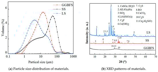
Figure 1.
Particle size-distribution and XRD patterns of the materials.
The specific surface areas of GGBFS, LS, and SS were 2525 m2/kg, 7623.6 m2/kg, and 10,128 m2/kg, respectively. The median particle sizes (D50) of GGBFS, LS, and SS were 10.68 μm, 6.368 μm, and 25.738 μm, respectively.
The sodium silicate was provided by Henan Gongyi Platinum Run Refractories Co. Ltd. (Zhengzhou, Henan province, China) with a purity of more than 98.5% and a modulus of 2.3 (SiO2/Na2O molar ratio). The NaOH was provided by Tianjin Kemao Co (Tianjing, China). The erosion solution utilised in the experiment was prepared using anhydrous sodium sulphate and anhydrous magnesium sulphate, both with a minimum content of 99.0%, provided by Tianjin Zhiyuan Chemical Reagent Co (Tianjing, China).
2.2. Preparation of Specimens
According to GB/T1346-2011 [35], 40 mm × 40 mm × 40 mm specimens were prepared. After moulding, the specimens were left to stand for 24 h before being demoulded and numbered. The specimens were placed in the standard curing room for curing (20 ± 2 °C, RH ≥ 95%). The details of mix proportions are shown in Table 2. The test was divided into five series. The effects of alkali activator content (A), modulus of alkali activator (B), w/b ratios (C), and mineral mixing ratios (D) on the compressive strength of GLS ternary AAMs and on the erosion of GLS ternary AAMs by magnesium sulphate and sodium sulphate solutions of different concentrations were investigated (E). Macroscopic performance tests were conducted after 3, 7, and 28 days. For the specimens subjected to sulphate erosion, they were immersed in water containing 5%, 10%, and 15% sodium sulphate solutions. The immersed specimens were photographed for appearance, analyzed for microstructure, and tested for strength at 28 days and 56 days.
Table 2.
Mix proportion (by wt.%).
2.3. Testing Procedure
2.3.1. Apparent Analysis
To evaluate visible signs of surface damage, such as swelling, cracking, and spalling, changes in apparent morphology were recorded at 28 days and 56 days for specimens immersed in 5%, 10%, and 15% sodium sulphate solutions.
2.3.2. Compressive Strength Analysis
After moulding, the specimen was left to stand for 24 h before being demoulded and numbered. It was then placed in a standard curing room for curing. Strength tests were carried out at 3, 7, 28, and 56 days of curing, following the Chinese standard GB/T17671-2021 [36].
2.3.3. Mass Loss and Corrosion Resistance
The rate of mass loss and the factor of corrosion resistance were calculated using the following formula:
Mass loss
where, ω is the rate of mass loss, mo is the mass of the specimen before immersion, and mi is the mass of the specimen after immersion in sulphate solution for i days.
Corrosion resistance
where, Kf is the corrosion resistance coefficient, fsi is the compressive strength of the specimen immersed in sulphate solution for i days, and fwi is the compressive strength of the specimen immersed in water for i days.
2.3.4. Microstructural Analysis
SEM (ZEISS GeminiSEM 300, Jena, Germany) and EDS (ZEISS GeminiSEM 300, Jena, Germany) were carried out to observe the microstructure and elemental content of the specimens. Following drying, the hydrated hardened body slurry was removed from the specimens. The specimens in the central region were then extracted and transformed into cubic blocks with side lengths of less than 5 mm. The specimens were soaked in anhydrous ethanol for seven days to terminate hydration, and dried in an oven (50 ± 2 °C). Subsequently, energy spectrum spot scanning was conducted to analyse the chemical composition of the products and to determine the changes in the elemental distribution of the calcium–silicon ratio and silicon–aluminium ratio. This provided a reference basis for the composition and strength change mechanism of the subsequent hydration products.
Following the condensation of cementitious materials into a specimen, soaked for seven days in anhydrous ethanol to terminate hydration, the specimens were removed from the vacuum drying oven and dried to a constant weight. The specimens were then ground to powder, with the objective of achieving a uniform particle size (particle size of approximately 45 μm or greater than a 200 mesh sieve) to enssure that the resulting powder had no particles that could be felt by the human hand. A total of 10 mg of powder was taken from each sample and subjected to XRD (Bruker D8 Advance, Bremen, Germany) and FTIR (Thermo Scientific Nicolet iS20, Madison, WI, USA), respectively.
3. Results and Discussion
3.1. Compressive Strength of GLS Ternary AAMs
3.1.1. Effect of Chemical Activators on Compressive Strength
Figure 2a illustrates the impact of alkali equivalence on the compressive strength of GLS ternary AAMs at a modulus of 1.3 M. The results indicate that the compressive strength of the cementitious materials increases and then decreases with an increase in alkali activator content. The compressive strength of each age reaches its highest point when the alkali activator content is 5%, with the compressive strength at 28 days of age being 72.58 MPa. Increasing the alkali activator content from 4% to 5% leads to a continuous rise in the alkali concentration in the GLS ternary AAMs. This increase in concentration results in a higher solubility of alumina and silica, leading to the generation of more dense hydration products, such as calcium silicate hydrate (C-S-H) and calcium aluminosilicate hydrate (C-A-S-H) gel, which in turn increases the compressive strength. When the alkali activator content exceeds 5%, the alkali concentration is too high, beyond the limit at which hydration products can be fixed, and a large number of dissolved Ca2+ in GGBFS and SS react rapidly with the silicate in sodium silicate [37]. This can cause a large number of hydration products to attach to the surface of the precursor and produce a precipitation. The presence of excess alkali ions in the GLS ternary AAMs system can cause damage to the hydration products after polymerisation, leading to a continuous decrease in compressive strength. At the same time, when the alkalinity is high, sodium ions attach to the surface of the solid and react with Al-OH or Si-OH, reducing the bonding of the C-S-H and C-A-S-H gels to the solid insoluble particles in the system. This results in a decrease in compressive strength [38]. Deviations from the optimal alkali activator content, either too high or too low, can negatively impact the reaction. Therefore, it is crucial to maintain the appropriate level of alkali activator content.
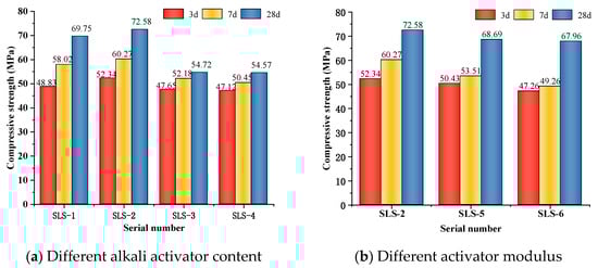
Figure 2.
Compressive strength under different alkali activator content and activator modulus.
The effect of the activator modulus on the compressive strength of the hardened body of GLS ternary AAMs at 5% alkali activator content is shown in Figure 2b. As can be seen from Figure 2b, the compressive strength of the GLS ternary AAMs decreases as the modulus increases. As the modulus increases from 1.3 to 1.5, the alkalinity of the solution decreases, the dissolution rate of ions in GGBFS, LS, and SS precursor decreases, the content of SiO2 in the solution gradually increases, and the number of hydration products generated decreases. At the same time, too much SiO2 will be precipitated in the form of amorphous silicate, and eventually a very low-strength, hardened body will exist in the cementitious material, causing the compressive strength of the cementitious material to decrease.
3.1.2. Effect of Water/Bender Ratio on Strength
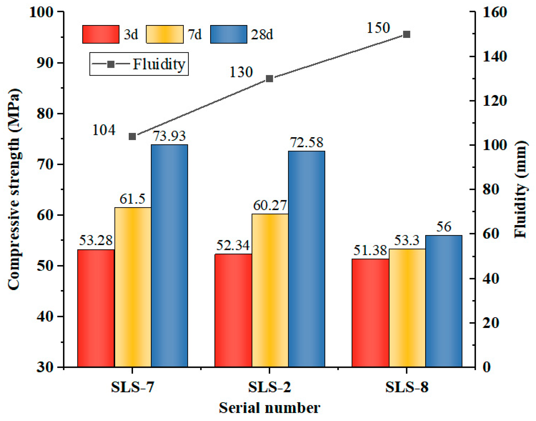
As illustrated in Figure 3, an inverse relationship was observed between the w/b ratio and the compressive strength of GLS ternary AAMs. This was accompanied by an increase in fluidity. Flash-setting phenomenon was observed in the GLS ternary AAMs when the w/b ratio was 0.38, making specimen casting and moulding difficult. The influence of w/b ratio on the fluidity of GLS ternary AAMs is evident from the increase in fluidity from 104 mm to 150 mm when w/b ratio increased from 0.38 to 0.42. The water absorption of S and SS was low. Although the incorporation of SS had a certain improvement effect on the fluidity of the GLS ternary AAMs, due to the porous structure of LS with large specific surface area and strong water absorption, it had a strong adsorption effect on water without the addition of water-reducing agent. This leads to the poor fluidity of the GLS ternary AAMs when the w/b ratio is low.
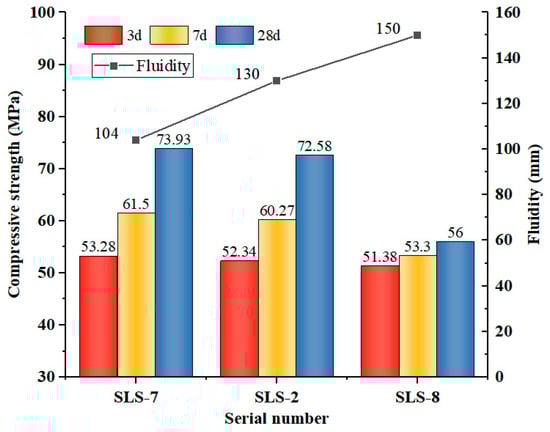
Figure 3.
Compressive strength and fluidity under different water/bender ratio.
The change in compressive strength was minimal when the w/b ratio was increased from 0.38 to 0.40. However, when the w/b ratio was increased to 0.42, the compressive strength at all ages decreased significantly. Excessive water diluted the alkali concentration of the activator, which affected its excitation effect on the raw material. At a w/b ratio of 0.42, the solubility of alumina and silica in GGBFS, LS, and SS decreased. Despite the increase in reaction time, the concentration of OH− in the GLS ternary AAMs remained low, generating a reduced content of hydration products. This resulted in a reduction in the concentration of hydration products, which in turn diminished the compressive strength. Furthermore, it was determined that during the initial stages (specifically on days 3 and 7), the influence of the w/b ratio on the material’s strength was not statistically significant. This is due to the fact that the early reaction rate was slow, the water mainly facilitated the contact of the reactants, the pore structure had not yet undergone a notable alteration, and the generation of hydration products was minimal. Consequently, the impact of varying w/b ratios on the early strength was insignificant. However, as time progressed, the modification of the w/b ratio exerted a considerable influence on the late strength and fluidity.
3.1.3. Effect of Mineral Mix Ratio on Strength
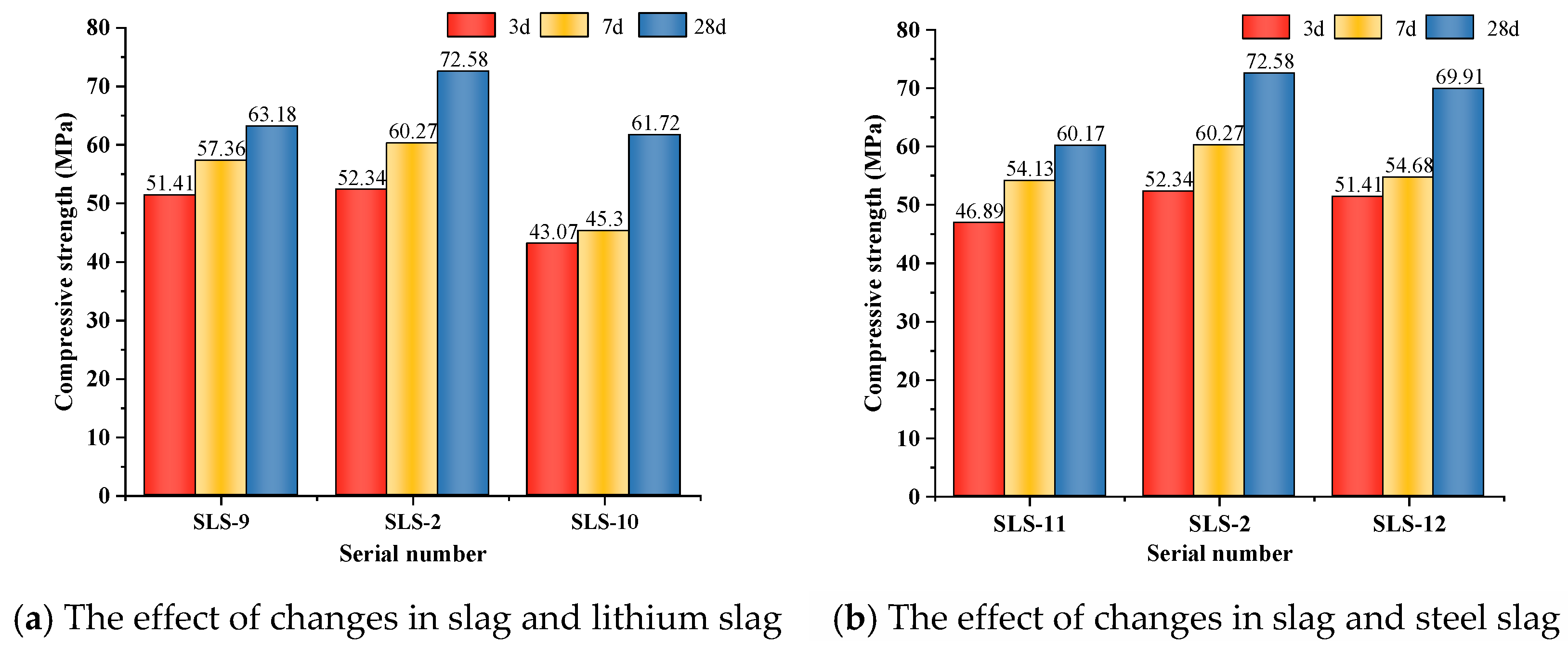
Figure 4a illustrates that, as the GGBFS/LS ratio increased, the compressive strength of GLS ternary AAMs initially increased and then decreased, while keeping the SS dosage constant at all ages. When the GGBFS/LS ratio was 3:1, the compressive strength at 28 days reached its highest value of 72.58 MPa. This suggests that, in the GLS ternary AAMs, higher slag dosage does not necessarily result in higher compressive strength. In fact, excessive GGBFS dosage can lead to a decrease in compressive strength. The low compressive strength is caused by the high GGBFS content of CaO, which exceeds 50%. Under alkali excitation, a large amount of Ca2+ dissociates and reacts rapidly with water glass in the silicate, producing numerous hydration products that attach to the precursor’s surface. This prevents further ion dissociation, which affects the formation of hydration products and the densification of the cementitious system, ultimately leading to reduced compressive strength.
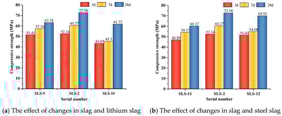
Figure 4.
Effect of compressive strength under different mating ratios.
Figure 4b illustrates that, when LS doping is constant, the compressive strength initially increases and then decreases with an increase in GGBFS/SS ratio. The highest compressive strength is achieved when the GGBFS/SS is 3:1, with a compressive strength of 72.58 MPa at 28 days. When the SS doping accounts for 30% of the gelling material, the compressive strength of the GLS ternary AAMs at each age is the lowest, especially with more obvious early strength reduction. The low activity of SS reduces the hydration reaction rate of the GLS ternary AAMs, resulting in a large number of pores in the cementitious material due to insufficient reaction, which reduces the structural densification. However, the large particle size of SS can cause non-uniform dispersion in cementitious materials, which can negatively impact the formation of hydration products and the densification of the cementitious system. Therefore, it is important to avoid excessive SS dosage as it can lead to significant early strength reduction.
3.2. Apparent Morphology Changes under Sulphate Attack
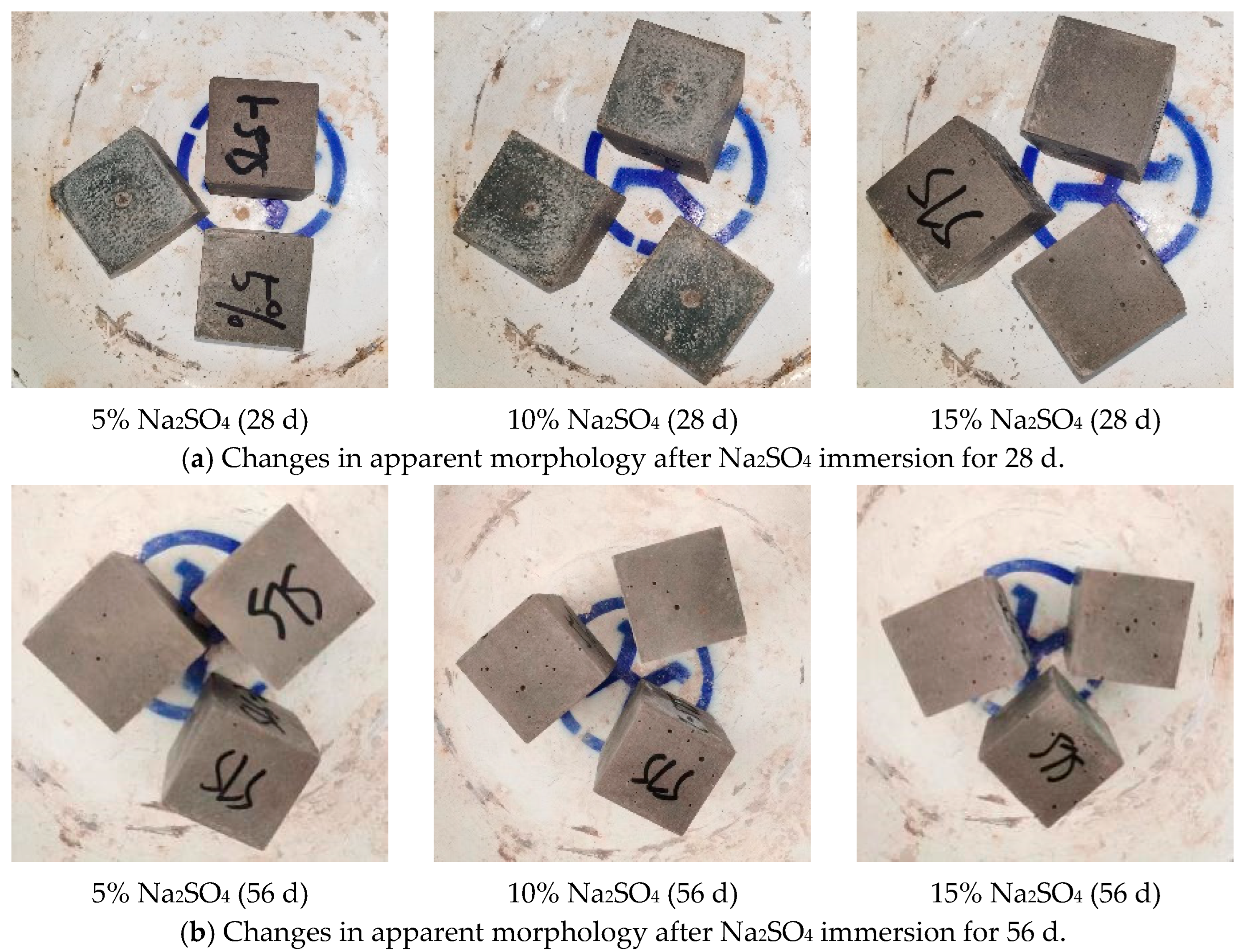
Figure 5 shows the apparent morphology changes of the GLS ternary AAMs in different concentrations of sodium sulphate erosion specimens. After 28 days of erosion in sodium sulphate solution, no changes were observed on the surface of the specimens when the concentration of the solution was increased from 5% to 10%. However, when the sodium sulphate solution was further increased to 15%, a small number of microscopic holes appeared on the surface of the specimens. After 56 days of erosion, eroded micropores appeared on the surface of all specimens. The number and size of micropores increased significantly with the concentration of the erosion solution. In the sodium sulphate erosion solution, only small holes appeared on the specimen’s surface, and no other apparent morphological changes occurred. The surface of the test specimens contained small holes that may be attributed to the presence of calcium oxide (CaO) in the raw material. This compound reacts with water to form calcium hydroxide (Ca(OH)2). When the specimen is immersed in a sodium sulphate solution, the sodium sulphate reacts with the calcium hydroxide to produce calcium sulphate (CaSO4), which is a water-insoluble precipitate. The reaction forms small pores on the surface of the gelling material. As the concentration of the sodium sulphate solution increases, the rate of reaction may also increase, resulting in an increase in the number and size of the pores.
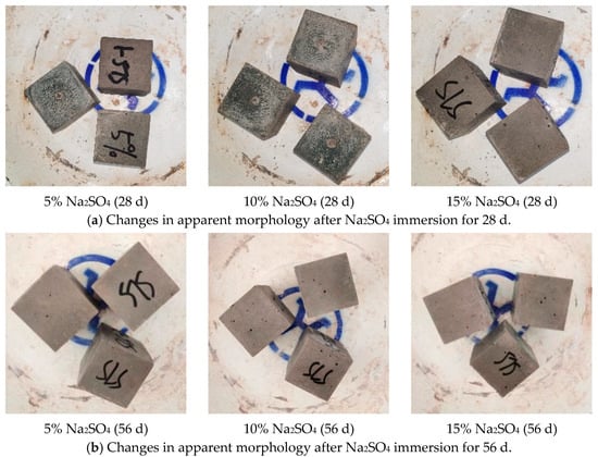
Figure 5.
Changes in apparent morphology after Na2SO4 immersion.
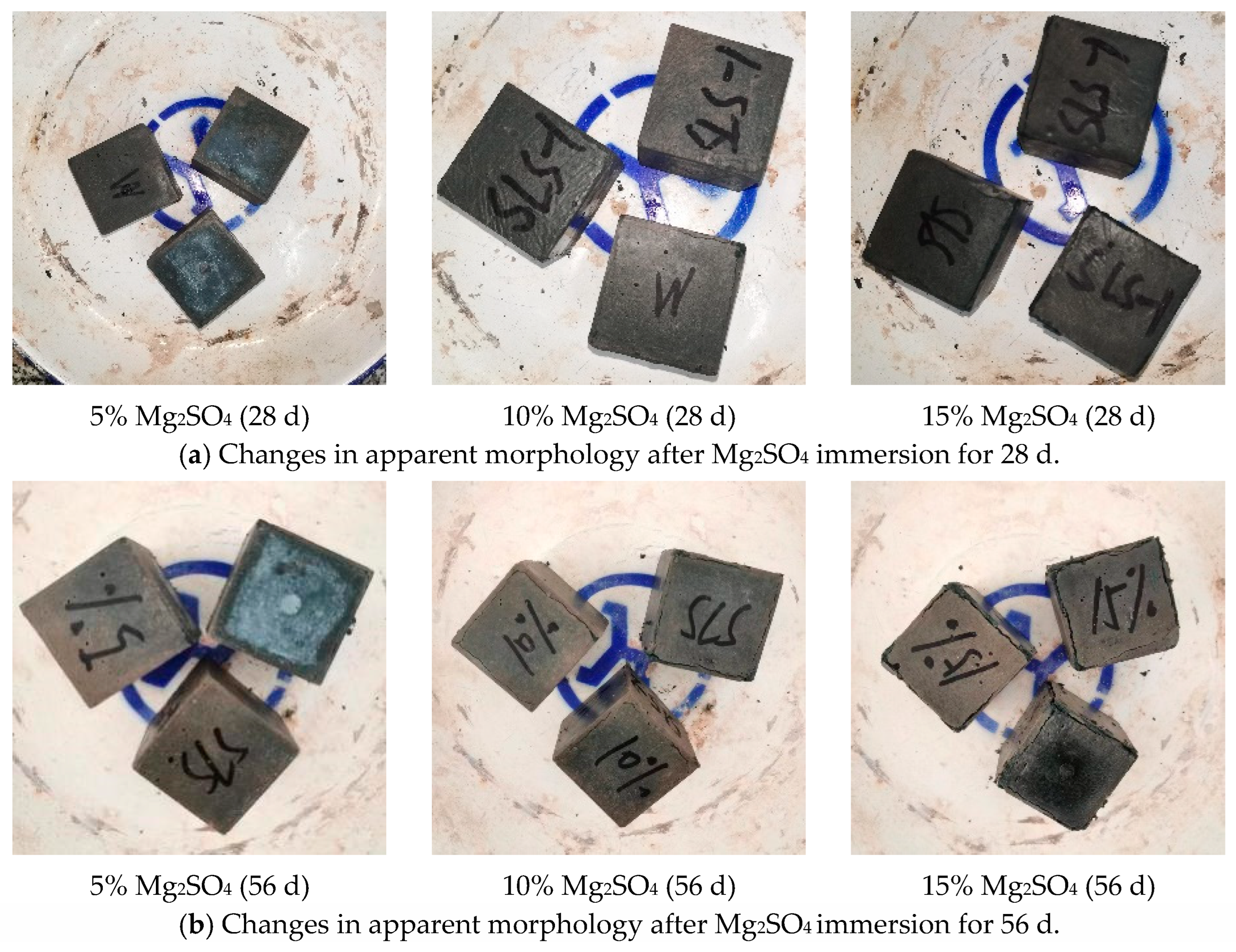
Figure 6 shows the changes in the apparent morphology of the eroded magnesium sulphate specimens. After 28 days of erosion in magnesium sulphate solution, the specimens appeared darker compared to those in sodium sulphate solution. Furthermore, as the concentration of magnesium sulphate solution increased, the specimens became progressively darker. When immersed in a 5% magnesium sulphate erosion solution, the specimen surface exhibited a light green colour. However, when the concentration was increased to 10%, the light green colour disappeared and there was no cracking or dissecting on the surface, edges, or corners of the specimen. At a concentration of 15%, tiny slurry dislodgment began to appear on the surface and at the ribs of the specimens. After 56 days of erosion, the green colour on the surface of the specimen was more extensive in the 5% solution and deeper within the specimen than at 28 days. Increasing the concentration from 5% to 10% caused the green colour on the surface of the specimen to start fading, but it also resulted in the specimen developing cracks at the ribs. When the concentration was increased to 15%, the cracks on the ribs of the test pieces became more apparent, and the corners of the test pieces began to break off. However, the surface of the test pieces did not show any significant damage.
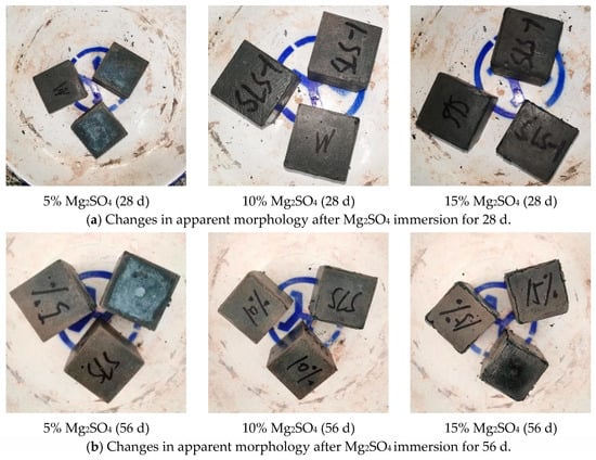
Figure 6.
Changes in apparent morphology after Mg2SO4 immersion.
3.3. Mass Loss Rates Changes under Sulphate Attack
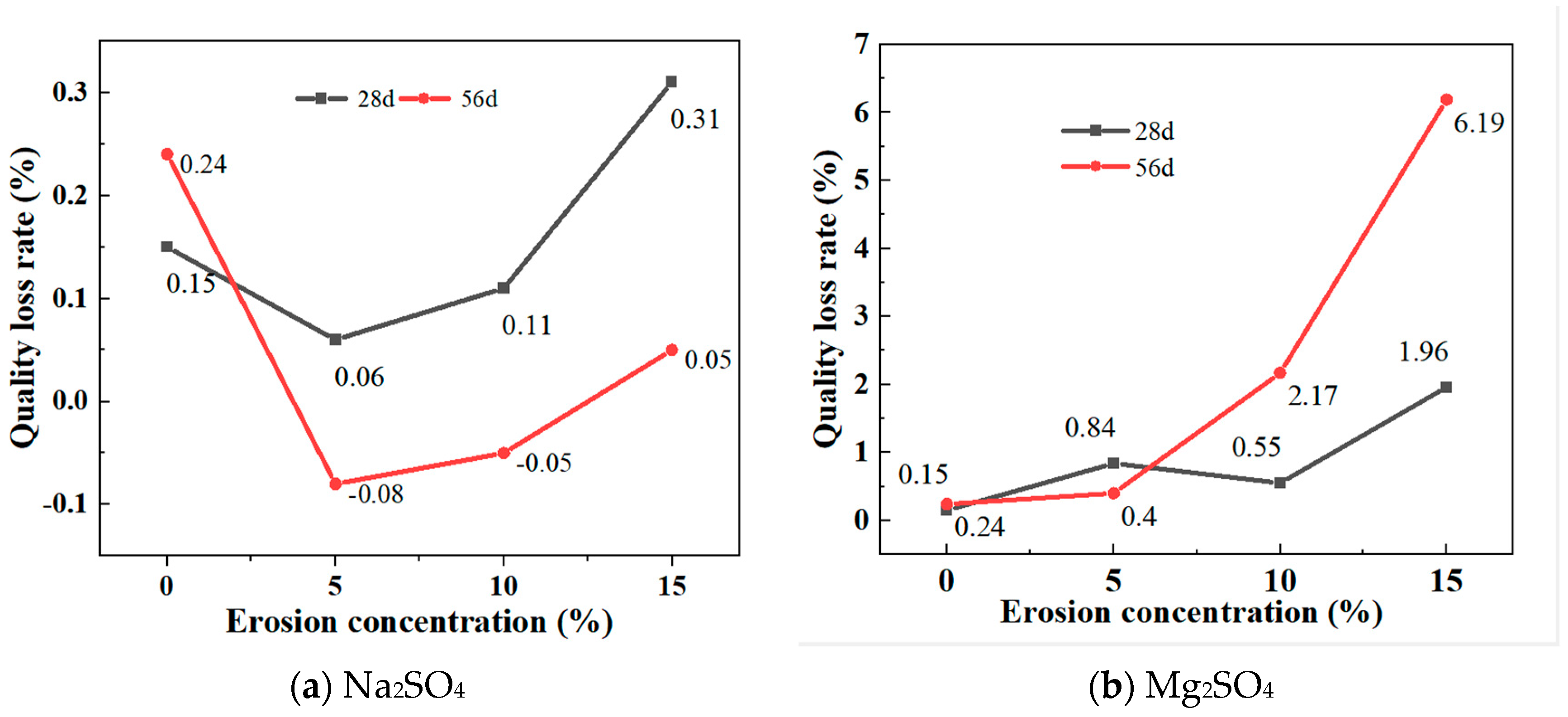
Figure 7a shows the mass change of GLS ternary AAMs after being immersed in different concentrations of sodium sulphate solution for 28 days and 56 days, respectively. After 28 days and 56 days of erosion, the specimen showed the same trend of change in different sodium sulphate solutions, and the mass decreased and then increased with an increase in solution concentration. After 28 days of immersion, the masses all increased and with the increase in solution concentration, the mass of the specimen increased significantly. When the concentration of the sodium sulphate solution was 15%, the increase in mass of the specimen was greater than the increase in mass in water, probably because at a higher sodium sulphate solution, Na2SO4 entered the inner part of the specimen through the pores on the surface of the specimen and reacted chemically with the material of the specimen, leading to a more significant change in the mass of the specimen. After 56 days of immersion, the mass of the specimens in 5% and 10% sodium sulphate solutions decreased, which may be due to the gradual dissolution of the material inside the specimens as a result of prolonged erosion. In the 15% sodium sulphate solution, the mass of the specimens increased, which may be due to the formation of a layer of gypsum on the surface of the specimens and the faster rate of hydration reaction in the high concentration solution, leading to an increase in the mass of the specimens.
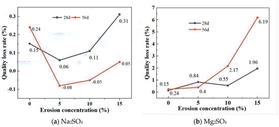
Figure 7.
Mass loss rates at different sulphate concentrations.
Figure 7b depicts the mass changes of GLS ternary AAMs following immersion in varying concentrations of magnesium sulphate solutions for 28 days and 56 days, respectively. It can be seen that the mass of the specimens increased after 28 days and 56 days of erosion in magnesium sulphate solution and, unlike erosion in the Na2SO4 solution, the mass increase after 56 days of erosion in 10% and 15% magnesium sulphate solution was much greater than that of the specimens eroded after 28 days. The greatest increase in mass occurred when the magnesium sulphate concentration was 15%, with a 1.96% increase in mass after 28 days and a 6.19% increase in mass after 56 days. Although prolonged magnesium sulphate erosion cracked the corners of the specimen, this was due to the reaction between MgSO4 and NaOH to produce Mg(OH)2 precipitation, and the higher the concentration, the more Mg(OH)2 was produced, and the greater the increase in mass.
3.4. Compressive Strength and Corrosion Resistance Coefficient Changes under Sulphate Attack
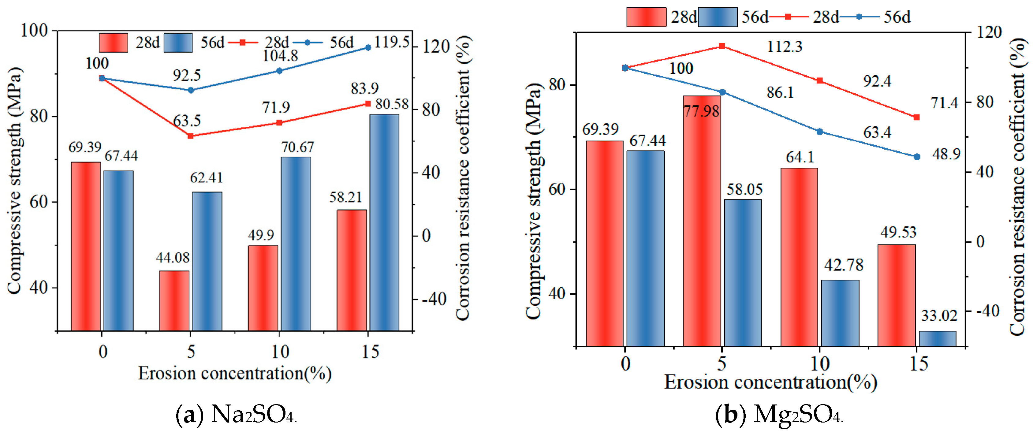
Figure 8a shows the changes in compressive strength of GLS ternary AAMs immersed in different time and sodium sulphate solution concentrations. It can be seen that the compressive strength of GLS ternary AAMs had the same trend of change after 28 days and 56 days of immersion, and the compressive strength increased with the increase in sodium sulphate solution concentration, and the compressive strength at 56 days was higher than that at 28 days at the same concentration. This indicates that GLS ternary AAMs displayed robust resistance to sodium sulphate erosion. Despite the initial inhibitory effect of sodium sulphate on specimen strength, it was observed that this effect was reversed in the long term, resulting in enhanced strength. As an external salt activator [39], sodium sulphate had a better excitation effect on GLS ternary AAMs as the concentration of the solution increased, resulting in an increase in the compressive strength of the specimens. As the specimens were immersed in the sulphate solution, the formation of calcium sulphate precipitate on the surface was relatively dense, which hindered ion exchange, resulting in lower hydration of the specimen, and the compressive strength was lower than that of the specimen immersed in the clear water solution. After 56 days of erosion, the presence of Na⁺ in the sodium sulphate solution was observed to act as an alkaline exciter, thereby promoting the formation of hydration products, including silicates and aluminates, within steel and lithium slags. The sodium ions and the alkaline exciter worked in concert over time to accelerate the hydration reaction within the material, forming additional gelling substances such as C-S-H and C-A-S-H gel. These hydration products filled the pore space within the material, resulting in a denser and stronger structure, which improved the compressive strength and durability of the material.
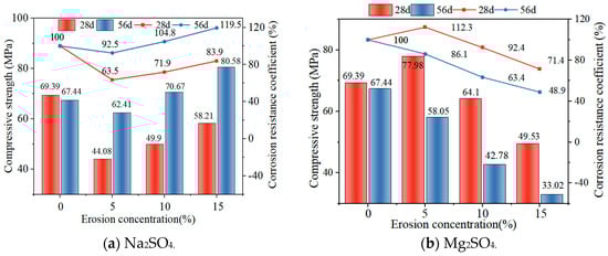
Figure 8.
Compressive strength at different sulphate concentrations.
Figure 8b illustrates the alterations in compressive strength and corrosion resistance coefficient of GLS ternary AAMs subjected to immersion for varying durations and concentrations of magnesium sulphate solution. Following immersion for distinct periods, the GLS ternary AAMs in magnesium sulphate solution exhibited a consistent pattern of change, with a decline in compressive strength observed as the concentration of magnesium sulphate solution increased. After 28 days of immersion, the compressive strength of the specimen in a 5% magnesium sulphate solution was 77.98 MPa, which was higher than the compressive strength of the specimen in clear water. This was due to the lower concentration of magnesium sulphate solution, which resulted in a greater excitation effect. The effect of the specimen was stronger than the destruction of the specimen. In the early stages of erosion, chemical reactions produced CaSO4 and Mg(OH)2, which filled the internal pores of the specimen or covered the surface of the specimen. This prevented erosive ions from entering the specimen. As the concentration of the magnesium sulphate solution increased, the quantity of SO42− and Mg2+ entering the specimen also increased. This resulted in a decalcification reaction between Mg2+ and the C-(A)-S-H gel formed, which in turn led to a decrease in the compressive strength of the specimen. Following 56 days of immersion in a 10% and 15% solution, the compressive strength of the specimen was found to be 42.78 MPa and 33.02 MPa, respectively. This was attributed to the prolonged erosion observed, which resulted in the formation of visible cracks at the points and corners of the specimen. Furthermore, the SO42− and Mg2+ were able to enter the inner part of the specimen more easily through the cracks, which resulted in a decrease in the number of C-S-H and C-A-S-H gels, and the replacement of calcium and magnesium silicate hydrates. This ultimately led to a significant decrease in the compressive strength of the specimen [40]. The corrosion resistance coefficient of GLS ternary AAMs immersed in magnesium sulphate solution decreased with an increase in erosion solution concentration. GLS ternary AAMs had a good resistance to magnesium sulphate erosion in the early stages, but the resistance of specimens to magnesium sulphate erosion deteriorated with an increase in erosion time.
3.5. X-ray Diffraction Analysis
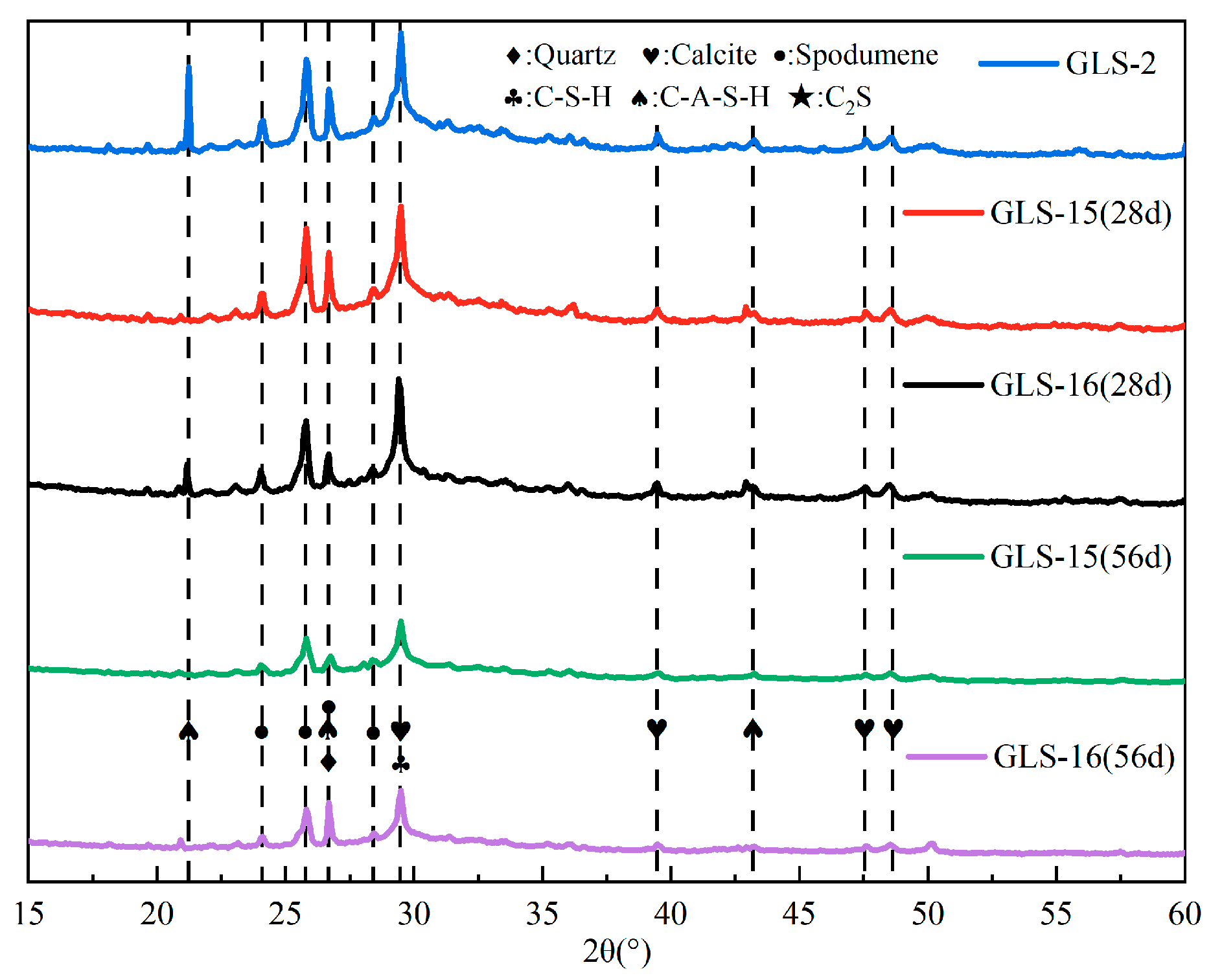
As can be seen in Figure 9, the main hydration products of the specimen under standard conservation conditions and those immersed in the sulphate solution were calcium silicate-aluminate hydrate (C-A-S-H) and calcium silicate hydrate (C-S-H). After immersion in sodium sulphate, the XRD results did not show any new diffraction peaks, such as gypsum or calcium vanadate. This indicates that the SO42− in the solution did not react with the products of the GLS ternary AAMs under sulphate erosion and still maintained good chemical stability, even under the high concentration of sulphate erosion. When the immersion time was 28 days, the presence of spodumene could be detected in the XRD results, indicating the presence of lithium slag that did not undergo hydration. When the soaking time was further increased, it could be seen that the diffraction peaks of spodumene decreased significantly. The spodumene in the specimen could continue to participate in the hydration reaction with an increase in time, which was also the main reason for the gradual increase in the compressive strength of the specimen under the condition of sodium sulphate erosion. There were also weak diffraction peaks of CaCO3 in the XRD pattern, which were due to the unreacted raw materials in the slag and steel slag, and the hydration products were carbonised by CO2 in the air [41]. There were no other Al-containing crystalline products in the XRD patterns, so it was assumed that the hydration reaction of Al2O3 produced a gel product.
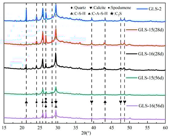
Figure 9.
XRD pattern of GLS ternary AAMs.
The destruction of materials caused by sulphate erosion is primarily due to the ingress of SO42− into the interior of materials through fine pores, where it reacts with calcium hydroxide (Ca(OH)2), hydrated calcium aluminates (C-A-H), and other components, generating gypsum, calcium alumina, and other expansive products. These expansive products cause the expansion and cracking of materials. By adjusting the ratio of solid waste and activator, the content of hydration products (e.g., Ca(OH)2 and C-A-H) that can react with SO42− to generate expansion products, such as gypsum and calcium alumina, can be reduced, thus inhibiting the generation of expansion products and limiting the volume expansion of materials.
3.6. Fourier Infrared Spectroscopy Analysis
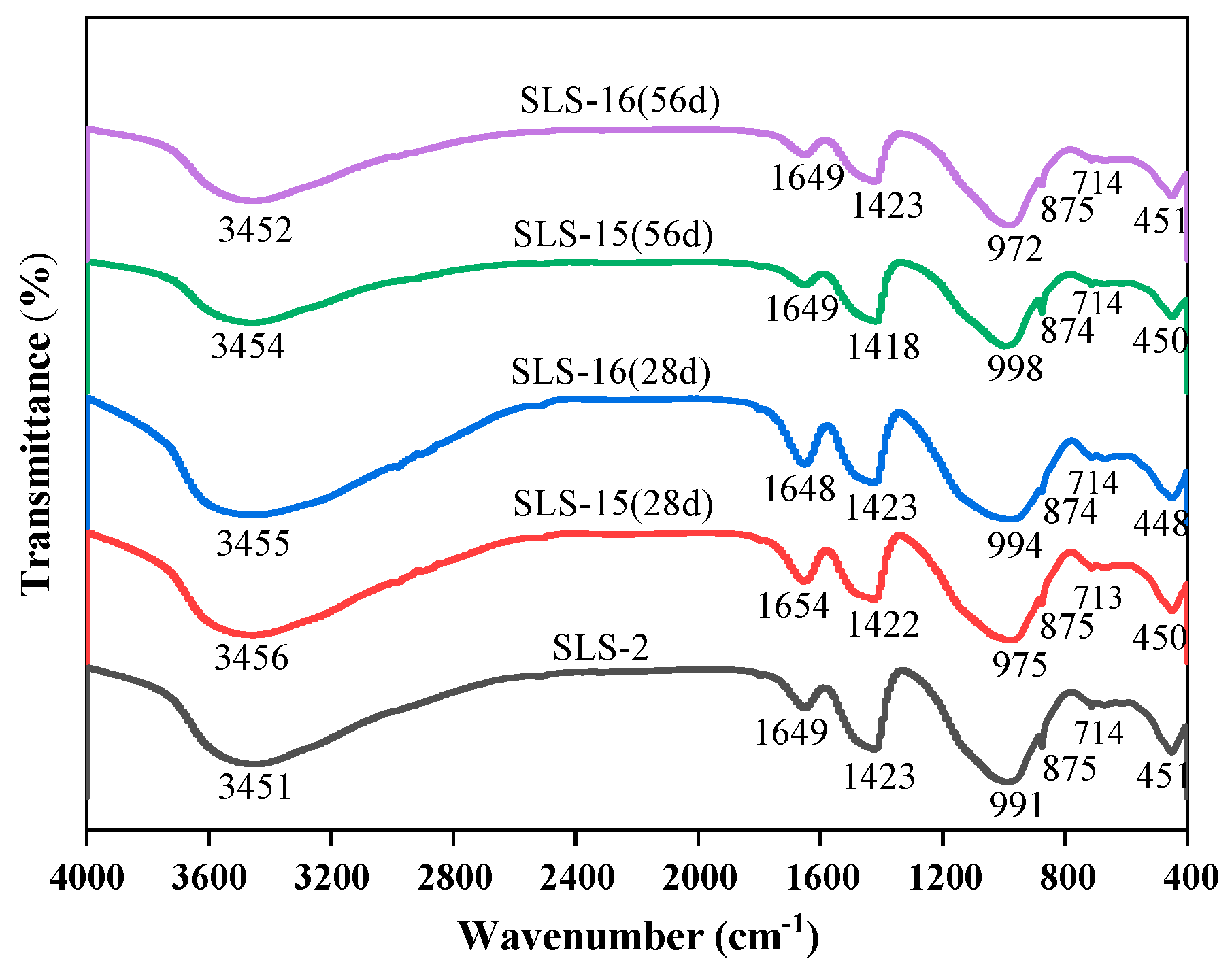
FTIR spectroscopy was employed to analyse the net mortar specimens of group GLS-2 following 28 days of maintenance in the standard maintenance room. The net mortar specimens of groups GLS-15 and GLS-16 were also analysed after 28 days. After 56 days of erosion in the erosion solution, the chemical bonding of each net mortar specimen was observed, as well as that of the uneroded specimen. The changes in the FTIR curves of each specimen are shown in Figure 10 and Table 3. The main band of the spectra of all the specimens was concentrated around 978 cm−1, which represents the formation of the silicate network structure [42]. The vibrational peaks were relatively sharp, which were asymmetric telescopic vibrational peaks of the Si-O bonds of the Q2 structure. The wave numbers at the main band were, in descending order, GLS-15 (56 d) with a wave number of 998 cm−1, followed by GLS-2 with a wave number of 991 cm−1, and lastly GLS-15 (28 d) with a wave number of 975 cm−1. From the trend of change, it could be seen that, as the time of sodium sulphate immersion increased, the stretching vibrational peaks of the Si-O bonds of the Q2 structure moved in the direction of a higher wave number, which led to the formation of C-A-S-H in [SiO4]4− tetrahedral polymerisation, thereby increasing the compressive strength of the specimen. In contrast, the opposite result was observed for magnesium sulphate. This is consistent with the results of the strength tests, which demonstrated that the specimens exhibited increased strength when immersed in a sodium sulphate solution and decreased strength when immersed in a magnesium sulphate solution.
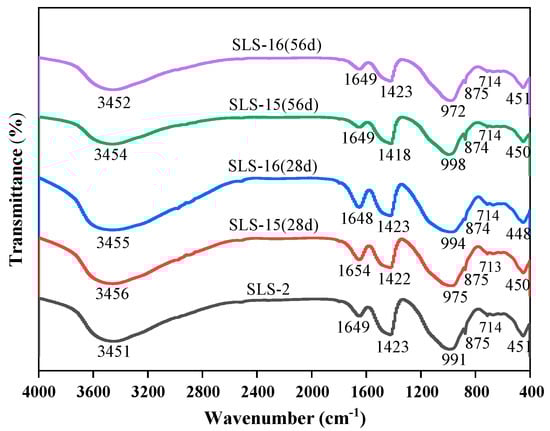
Figure 10.
FTIR spectra changes in GLS ternary AAMs.
Table 3.
Assignments of the bands in the FTIR spectra of GLS ternary AAMs.
The absorption peak near 450 cm−1 is primarily attributed to the bending vibration of O-Si-O bonds in the silica–oxygen tetrahedra. The peaks of the GLS-16(28 d) specimen exhibited greater sharpness and strength in this region, which suggests that the short-term erosion in magnesium sulphate solution mitigated the damage to the specimen, preserving a relatively intact silicate network structure within the specimen’s interior. A minor absorption peak was observed at approximately 715 cm−1, which was attributed to the deformation vibration peak of the Si-O-Al bond. This indicates that a small amount of Si-O-Al was present in the gel structure. Concomitantly, the peak near 875 cm−1 of the specimen that was immersed in sodium sulphate solution for an extended period of time became sharp, indicating that the intensity of the peak at that location increased significantly. This suggests that the content of the Si-O bond inside the specimen increased, which may be indicative of enhanced aggregation of the gel structure within the specimen. This, in turn, could potentially lead to an improvement in the specimen’s compressive strength. This can be observed in the peak at that location of GLS-15 (56 d) peak intensity, which also verifies that it had the highest compressive strength. It has been demonstrated that SO42− antisymmetric tensile vibration occurs at approximately 1120 cm−1 and bending vibration at 610 cm−1 [43]. One of these vibrations was present in the ettringite structure at 610 cm−1, while the other was present in the molecular structure of gypsum at 1120 cm−1. The absence of absorption peaks at either location in the figure was consistent with the absence of diffraction peaks for gypsum and calcovanillite in XRD. The band near 1650 cm−1 was attributed to O-H bending vibrations. The absorption band of H2O shifted towards higher wave numbers with increasing immersion time, indicating the conversion of adsorbed water to water of crystallisation.
In conclusion, the structures of C-A-S-H gels in all groups of specimens were comparable, with all of them exhibiting a preponderance of Si-O bonds belonging to the Q2 structure, accompanied by a minor presence of Si-O-Al bonds. The GLS ternary AAMs were soaked in a sodium sulphate solution, which shifted the main bands at the higher wave number, accelerating the polymerisation of [SiO4]4− tetrahedra in the C-A-S-H gels and enhancing the compressive strength of the specimens. In contrast, magnesium sulphate solutions yielded the opposite result. Furthermore, no new absorption peaks were observed in the GLS ternary AAMs following soaking in the sulphate solution for different times. This was consistent with the absence of new diffraction peaks in the XRD results, indicating that the GLS ternary AAMs exhibited good chemical stability in the sulphate solution.
3.7. Scanning Electron Microscopy and Energy Dispersive Spectroscope Analysis
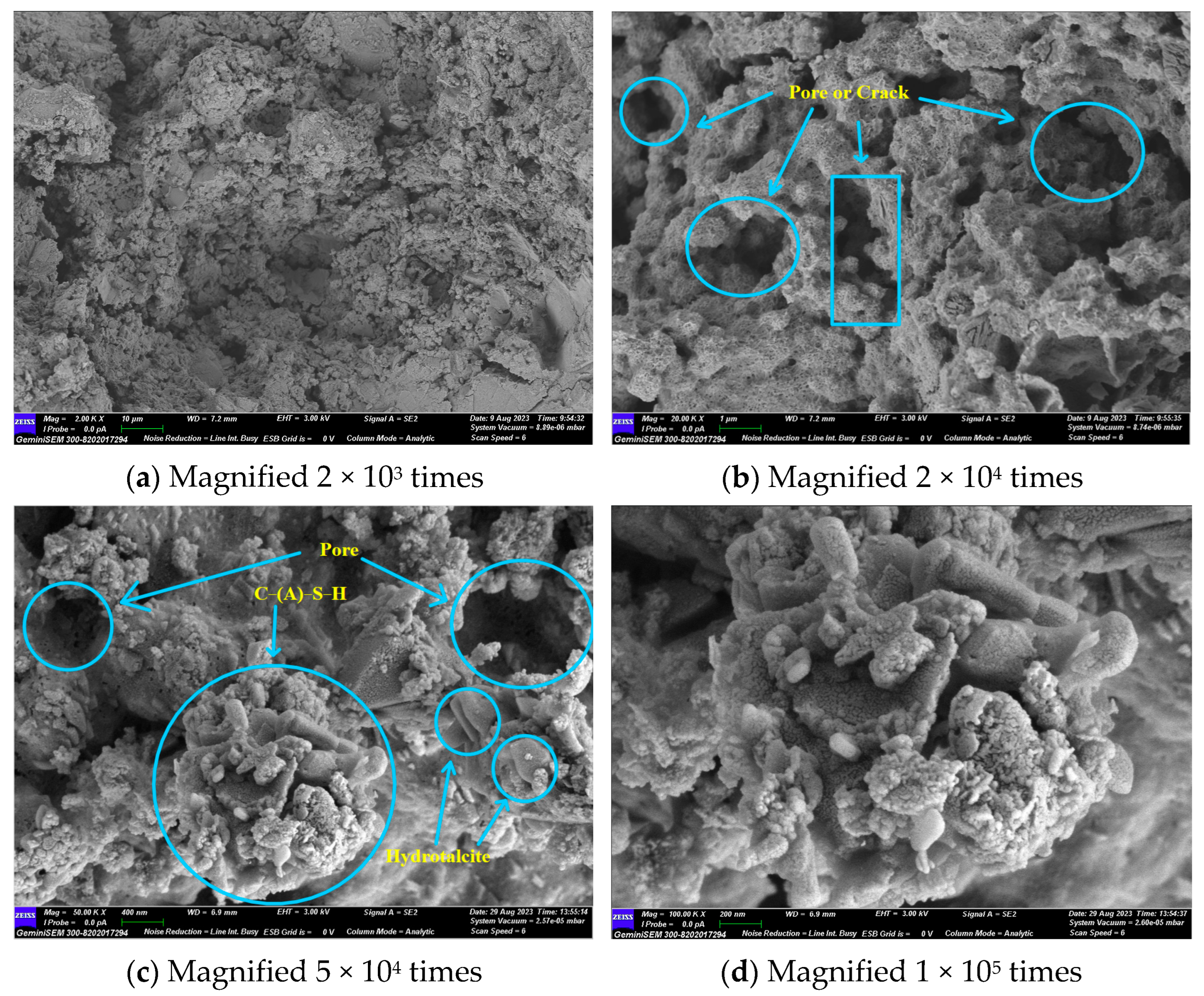
Figure 11 illustrates that the primary hydration products are C-(A)-S-H gel and hydrotalcite. No hydration products such as calcium hydroxide and calcium aluminate hydrate, which are highly susceptible to erosion, were observed. Ca(OH)2, as an intermediate product of the hydration reaction, was consumed by the secondary volcanic ash reaction with SiO2 and Al2O3 to produce C-(A)-S-H gel. It is evident that the material exhibited clear fissures and voids, and that unhydrated particles were present. In light of the lithium pyroxene observed in the XRD results, it can be postulated that the unhydrated particulate matter was lithium slag.
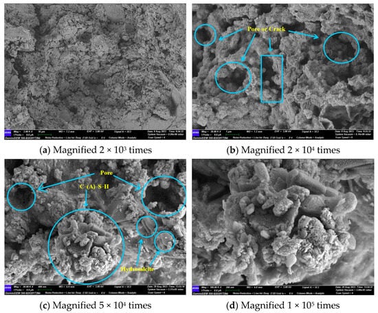
Figure 11.
GLS−2 group SEM diagram.
Upon magnification to 50,000 times, it could be observed that the stacked sheets of hydrotalcite were attached to the gel, and a small amount of C-(A)-S-H gel was attached to the hydrotalcite. The two interlaced with each other, reducing the pores in the material’s structure. However, a considerable number of pores and cracks still remained. The C-(A)-S-H gel and the unhydrated particles formed a network structure, which improved the compressive strength of the GLS ternary AAMs.
Hydrotalcite is a layered double hydroxide whose unique anion exchange properties allow it to remove anions from the surrounding solution. Sulphate ions (SO42−) have the second highest affinity for the interlayer of hydrotalcite, after carbonate (CO32−), and this property has been successfully used to remove sulphate ions from different solutions [44]. Therefore, the formation of hydrotalcite may be responsible for the enhanced sulphate resistance provided by GLS ternary AAMs
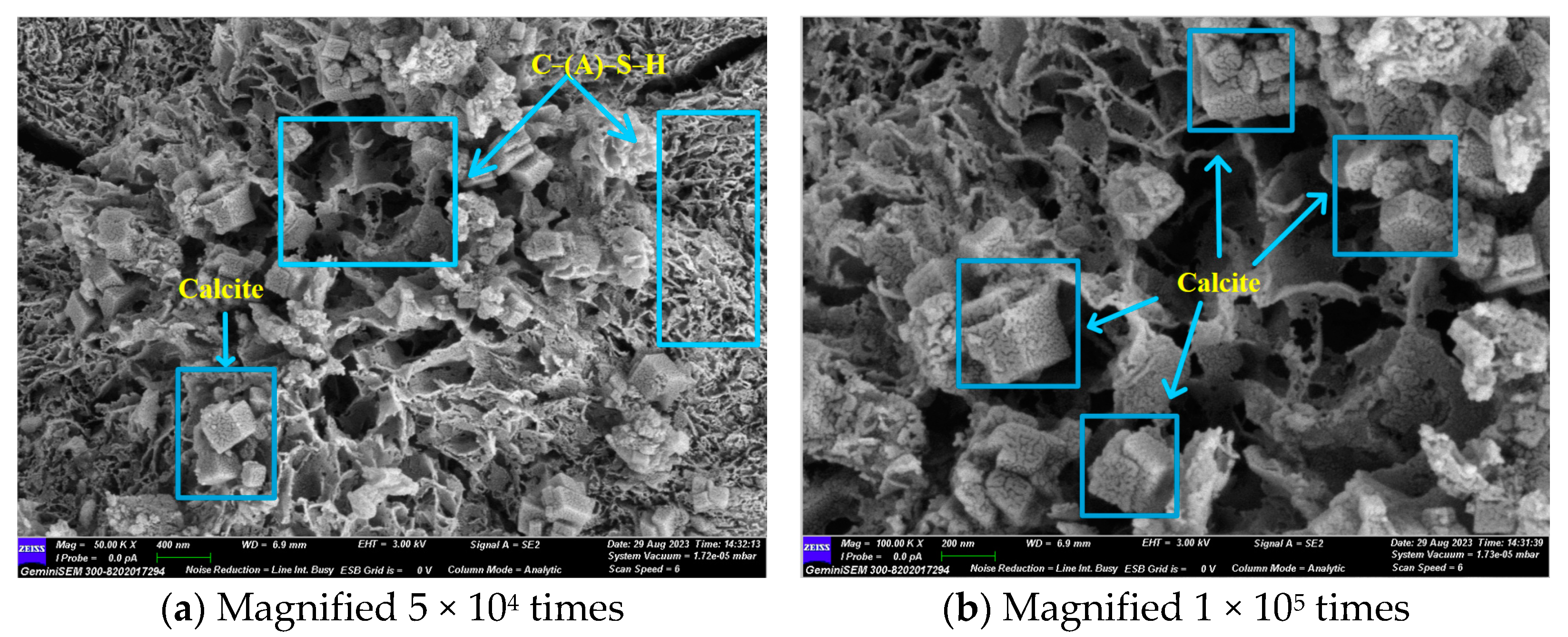
In Figure 12a, a significant cleavage can be observed, and the C-A-S-H gel morphology is predominantly granular. Combined with FTIR analysis, it can be seen that, at that time, the gel polymerisation was low, which indicates that the densification inside the specimen was low. Upon magnification to 100,000 times, the lithium slag and steel slag exhibited minimal activity, resulting in the presence of numerous unreacted particles within the system. As the specimen was immersed in a sodium sulphate solution, sodium ions and hydroxide ions combined to form sodium hydroxide (NaOH). The alkali concentration in the system was too high, exceeding the limit of the hydration products that could be fixed. This resulted in a large number of hydration products attaching to the surface of the precursor, which in turn produced precipitation. This affects the further dissolution of ions, preventing them from diffusing into the solution. Consequently, the further occurrence of hydrolysis and gel polymerisation was prevented, resulting in a lower compressive strength of the specimen.
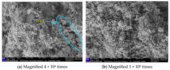
Figure 12.
GLS−15 (28 d) group SEM diagram.
At 56 days, with the extension of the reaction age, it can be observed in Figure 13a that the morphology of the C-(A)-S-H gel underwent a transformation from the initial granular shape to a more compact foil-like structure. This change was accompanied by an increase in the polymerisation of the gel structure and the appearance of hexagonal lumps of calcite. The hexagonal lumps of calcite were attached to the foil gel, indicating that they were not unreacted from the raw material but had been formed by a carbonation reaction with CO2 in the air. The newly generated calcite in the form of hexagonal specimens provided a new nucleation point for the gel, and could reduce the internal voids of the material, making the internal structure of the material denser. Consequently, the compressive strength of the GLS ternary AAMs was enhanced from 58.21 MPa at 28 days to 80.58 MPa at 56 days.
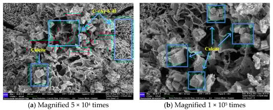
Figure 13.
GLS−15 (56 d) group SEM diagram.
Following the dissolution of the GLS ternary AAMs in sodium sulphate, no expansive hydration products such as gypsum and ettringite were generated, and no sodium sulphate crystals were observed. This indicates that no physical or chemical erosion of the specimen occurred. Consequently, after GLS ternary AAMs were eroded by sulphate, GLS ternary AAMs demonstrated good resistance to Na2SO4 erosion, and the compressive strength was not only not reduced, but also improved.
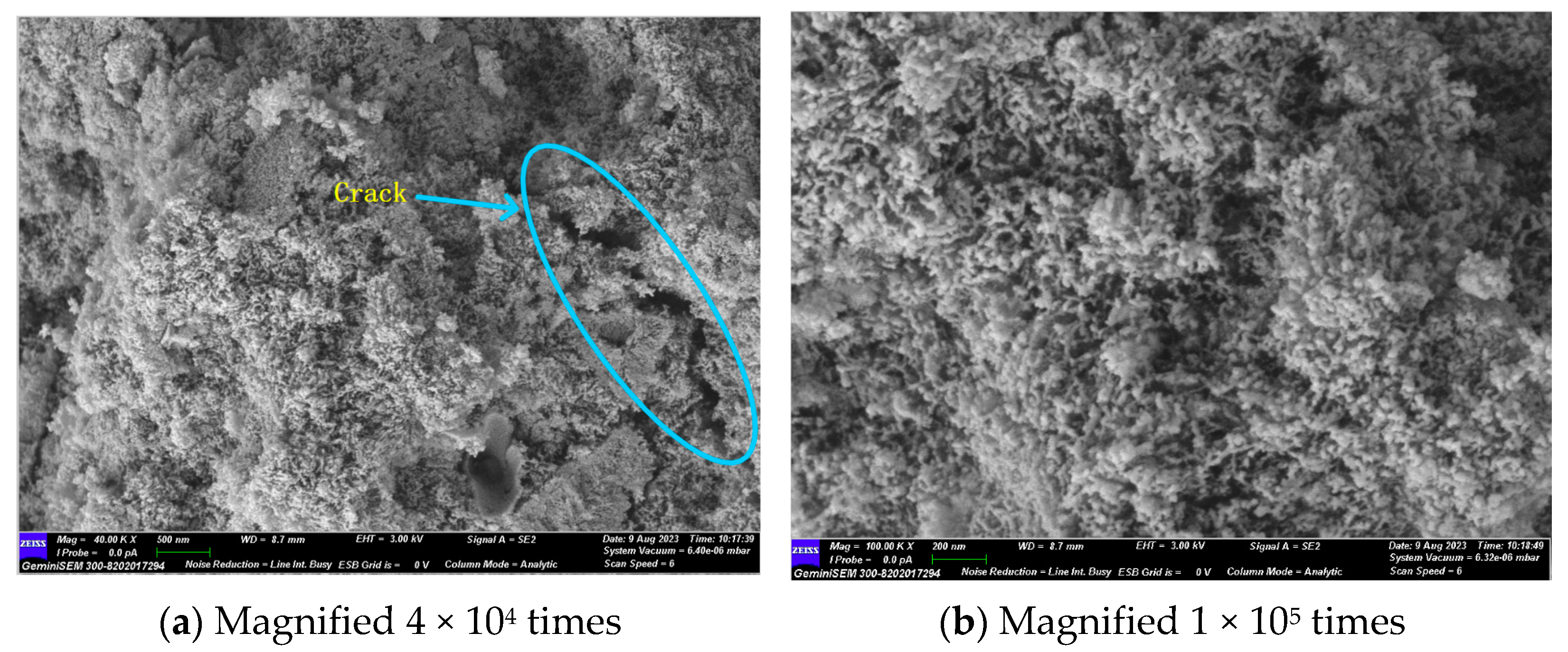
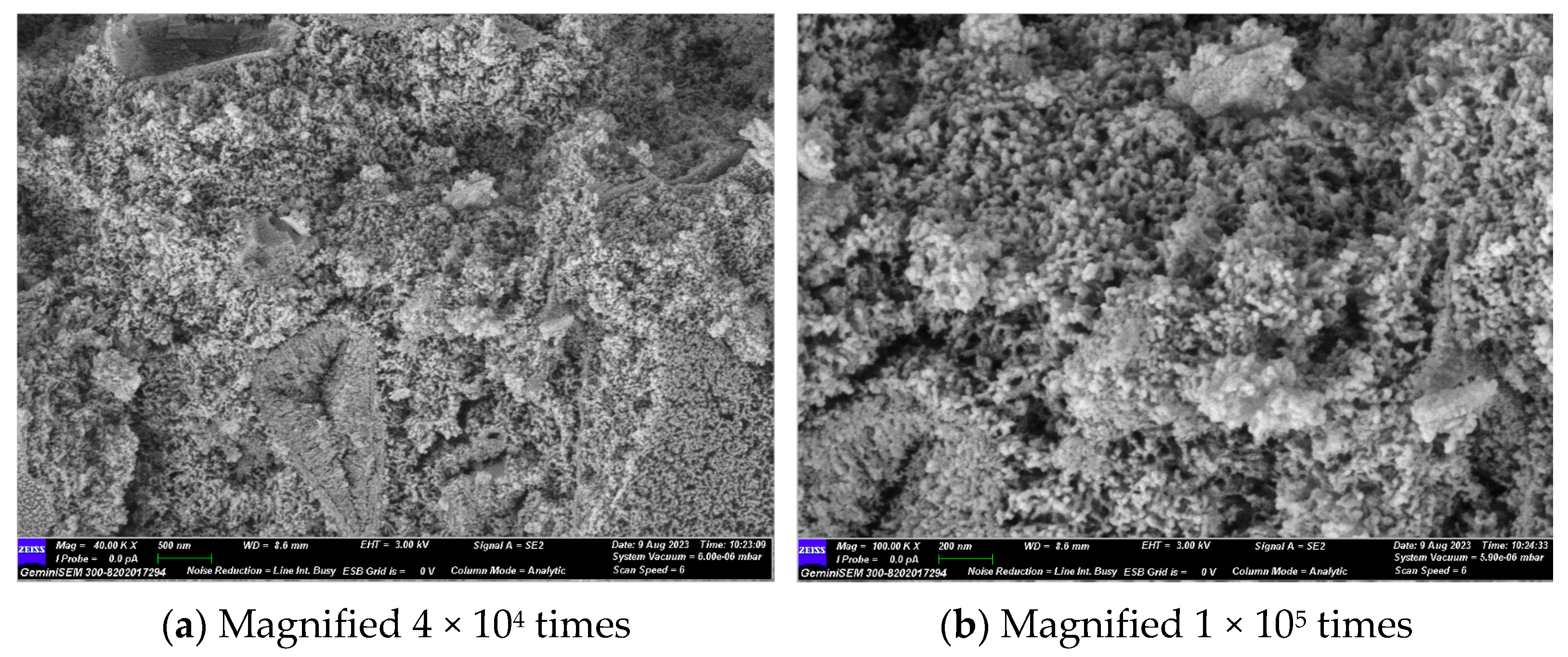
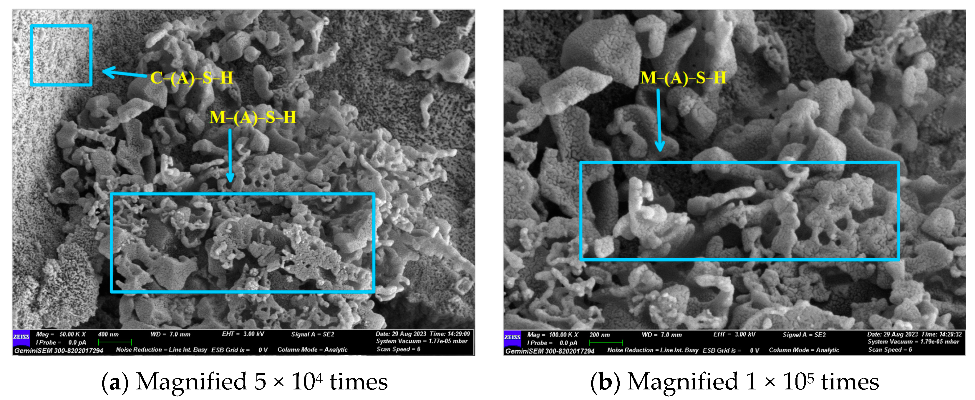
Figure 14 and Figure 15 illustrate the microscopic morphology of the GLS ternary AAMs immersed in magnesium sulphate solution for different times. After 28 days of immersion in magnesium sulphate solution, no large cracks were produced inside the specimen, as shown in Figure 14, which is similar to the microscopic morphology when immersed in sodium sulphate solution for 28 days. The overall degree of hydration reaction inside the specimen was low. It is evident that the overall microscopic structure of the GLS ternary AAMs is complex and inhomogeneous, comprising a variety of unreacted particles of different sizes connected by the products of incomplete hydration. Additionally, some heterogeneous hydration products were connected with each other and densely piled up together. After 28 days of soaking and erosion in magnesium sulphate solution, no new types of hydration products were observed. As the soaking time increased, the Mg2+ ions began to decalcify the C-(A)-S-H gel at 56 days, resulting in the formation of a new type of uncemented M-(A)-S-H gel within the specimen. As illustrated in Figure 15, the hydration products exhibit diverse morphologies, yet they fail to form a compact structure. Instead, they appear to be loosely associated, akin to a “skeleton” of interconnecting elements. This lack of cohesion is evident in the specimen, which exhibits a low compressive strength. The damage caused by magnesium sulphate to GLS ternary AAMs is primarily attributed to the presence of Mg2+, rather than sulphate. In the context of sulphate erosion, it is essential to consider the impact of cations on cementitious materials.
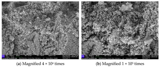
Figure 14.
GLS−16 (28 d) group SEM diagram.

Figure 15.
GLS−16 (56 d) group SEM diagram.
Figure 16 and Figure 17 illustrate the EDS test curves of the hydration products of specimens GLS-2 and GLS-15 (56 d), respectively. The chemical element analyses at the location of the hitting point are presented in Table 4. Table 4 indicates that the chemical element composition of the hydration products of GLS ternary AAMs was dominated by O, Si, Ca, and Na, followed by Al and Mg. This suggests that the gel products of the two groups of specimens are C-A-S-H. For cementitious materials, the Ca/Si ratio exhibited a linear and positive correlation with compressive strength. The Ca/Si ratio of specimens in the GLS-15 group was 1.54, which was higher than that of the GLS-2 group (0.74). This is consistent with the compressive strength test results.
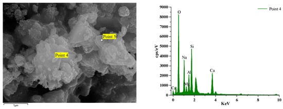
Figure 16.
GLS-2 group EDS diagram.
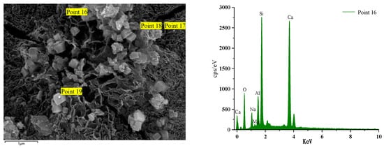
Figure 17.
GLS-15(56 d) group EDS diagram.
Table 4.
Element composition of reaction products of GLS ternary AAMs cementitious material system/at%.
GLS-2 is the specimens under standard maintenance conditions. Point 4 is the hit point on the specimens. It can be observed that the content of Mg was higher at the hit point position. This was due to the fact that the slag contained more than 5% MgO, which was hardly involved in the reaction. Consequently, it did not exist in the gel. In contrast, the Al element existed in the Al₂O₃, which was involved in the hydration reaction, and will therefore be present in the gel. At the same time, it can be seen that the content of the hydration product element Na+ at Point 4 was also very high, reaching 7.63%. The combination of XRD analysis demonstrated that Na+ was not involved in the formation of crystals, indicating that it was present in the gel. Although XRD analysis did not identify the presence of the N-A-S-H gel, this does not preclude its possible presence. The high sodium content and lack of involvement in crystal formation indicate that the N-A-S-H gel may be present in the sample.
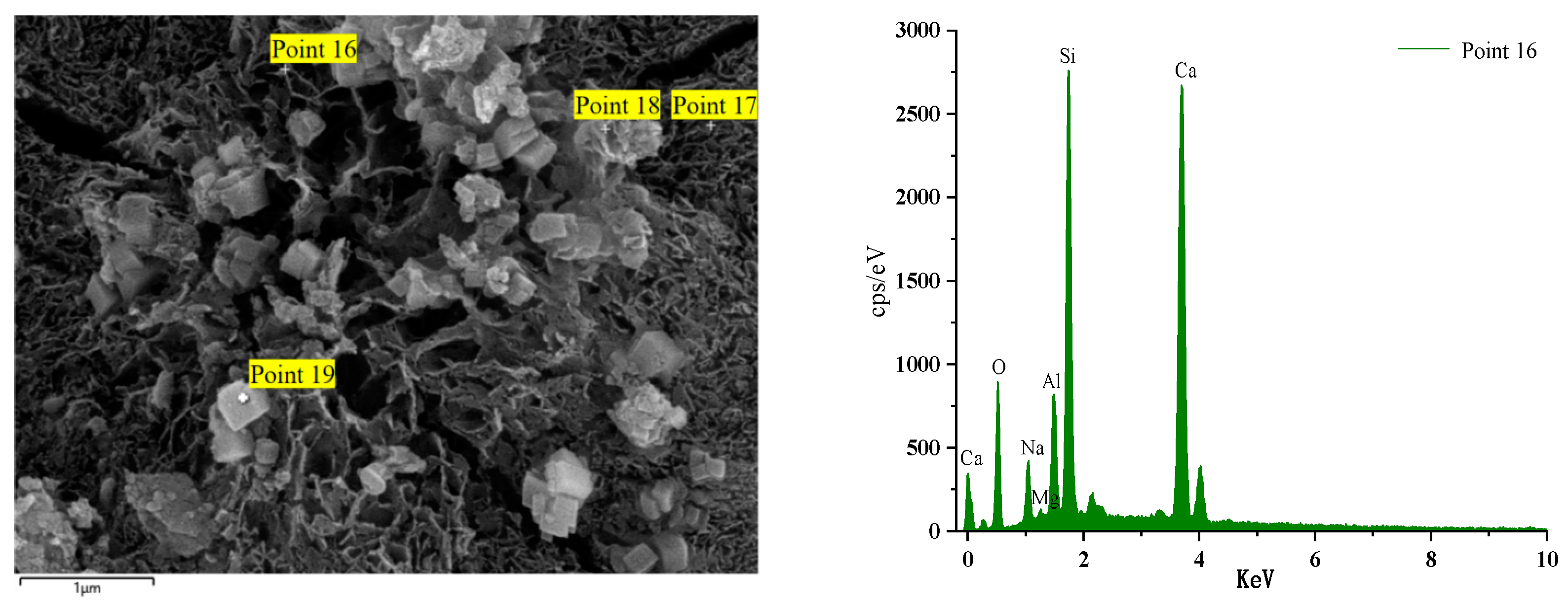
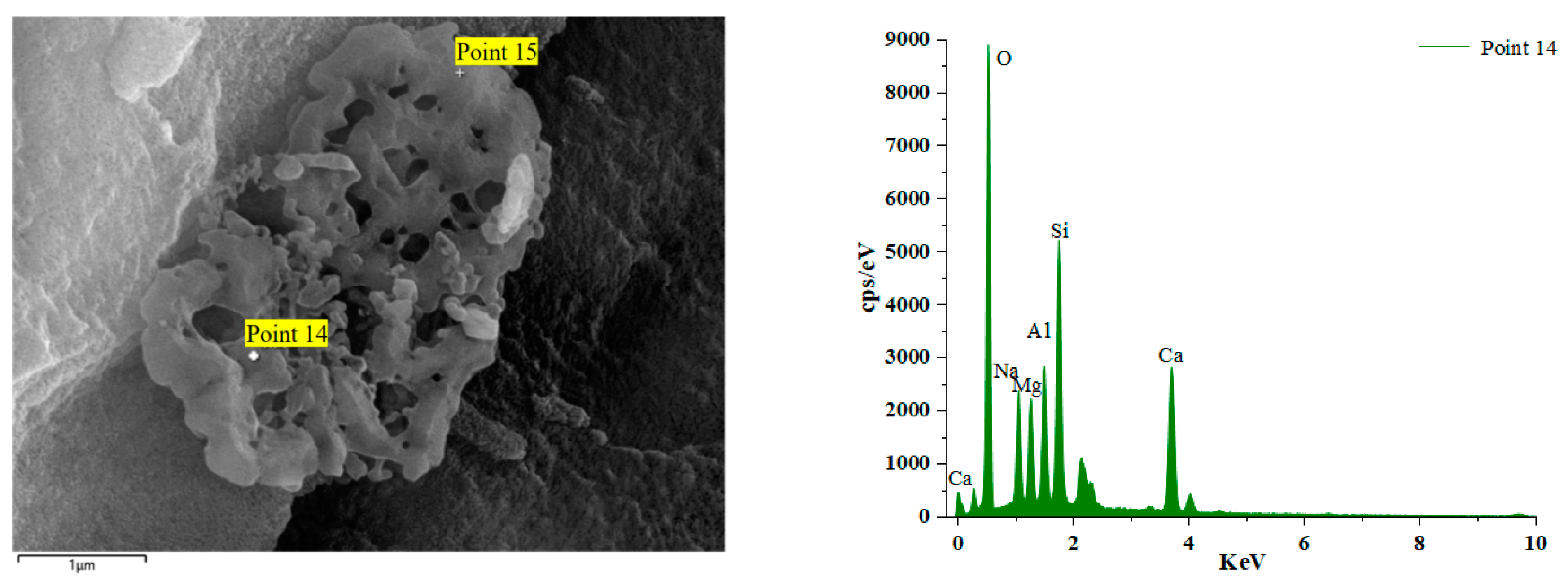
Figure 18 illustrates the EDS spectrum of a specimen after 56 days of immersion in a sodium sulphate solution. The elemental analysis of the hydration products at the position of Point 16 reveals a significant increase in the content of the Ca element. The other dominant elements are Si, O, and Al. The primary reason for this phenomenon is the admixture of steel slag. During the late hydration reaction of alkali activator components and co-stimulation, steel slag activity is activated to the maximum extent. Over an extended period of maintenance, the products intertwine with each other, resulting in an increased density within the structure, enhanced compressive strength, and a GLS specimen with excellent chemical stability under the erosion of sodium sulphate solution. Point 14 is the GLS net specimen block in magnesium sulphate solution after soaking for 56 days. Table 4 shows that the content of the Mg element increased significantly. The Mg2+ ion decalcified the C-(A)-S-H gel, resulting in the formation of the M-(A)-S-H gel within the specimen. This was corroborated by the SEM images of the new type of gel, which exhibited no cementation force. The erosion of magnesium sulphate solution by GLS specimens produced M-(A)-S-H gel, which resulted in a decrease in the strength of the cemented material.
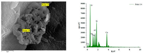
Figure 18.
GLS-16(56 d) group EDS diagram.
4. Conclusions
In this study, GGBFS, LS, and SS were used to prepare AAMs with different modulus of alkali activator, alkali activator content, w/b ratios, and mineral mixing ratios as the variables. Changes in the appearance of the test specimens were observed, the rate of mass loss was measured, and a compressive strength test was carried out to calculate the corrosion resistance coefficient. The hydration reaction products, the composition of the physical phases, and the microstructure of the GLS ternary AAMs were analysed using microscopic testing methods to assess the sulphate resistance of the GLS ternary AAMs. Based on these test results, the following conclusions can be drawn:
(1) The main hydration products of GLS ternary AAMs were C-(A)-S-H and hydrotalcite at the age of 28 days. There were no hydration products such as calcium hydroxide and hydrated calcium aluminate, which are very susceptible to erosion, etc. Ca(OH)2, as an intermediate product of the hydration reaction, was consumed with SiO2 and Al2O3 in a secondary volcanic ash reaction to form C-(A)-S-H gel.
(2) In the microstructure of the GLS ternary AAMs at 28 days, the hydrotalcite and the flocculent C-(A)-S-H gel were interspersed with each other, which reduced the pores in the structure, but there were still more pores and cracks. The C-(A)-S-H gel and the unhydrated steel slag and lithium slag particles formed a network structure, which improved the compressive strength of the GLS ternary AAMs, which was 69.39 MPa at 28 days.
(3) When soaked in sodium sulphate solution for 28 days, the degree of hydration reaction was low and there were cracks, and the generated C-(A)-S-H gel was granular with a low degree of polymerisation. At 56 days, with the prolongation of the reaction age, the morphology of the C-(A)-S-H gel was changed from granular to compact film, with a higher degree of polymerisation, and there were hexagonal calcite specimens which provided nucleation points for the generation of the gel and increased the internal compactness of the structure, so that the compressive strength of the GLS ternary AAMs was improved. The compressive strength of the GLS ternary AAMs was improved due to the internal compactness, and the GLS ternary AAMs did not produce expansion hydration products such as gypsum and ettringite, and no sodium sulphate crystals were detected after sodium sulphate soaking and erosion. This shows that the GLS ternary AAMs had no physical or chemical erosion, and had a good resistance to sodium sulphate erosion.
(4) After magnesium sulphate erosion, the GLS ternary AAMs will not change in the short term, but over time Mg2+ will cause decalcification of the C-(A)-S-H gel, resulting in M-(A)-S-H gel with no binding force. The gel is loose, like a “skeleton” piled up, resulting in a decrease in the compressive strength of the specimen. The resistance to magnesium sulphate erosion of the GLS ternary AAMs decreased over time.
(5) To improve the sulphate resistance of cementitious materials, the formation of expansion products such as gypsum and ettringite can be inhibited by adjusting the type and proportion of solid waste and reducing the content of hydration products (e.g., Ca(OH)2 and C-A-H) that can react with SO42− to form expansion products such as gypsum and ettringite. Also, when considering sulphate erosion, special attention must be paid to the cations in the sulphate, which can be more damaging than the sulphate itself.
Author Contributions
S.Z.: data curation, formal analysis, investigation, methodology, visualisation, writing—original draft. Y.Z.: data curation, formal analysis, investigation, methodology, funding acquisition, writing—original draft. J.Z.: investigation, supervision, review and editing. Y.L.: investigation, supervision, review and editing. All authors have read and agreed to the published version of the manuscript.
Funding
This research was funded by the Key Project of the National Natural Science Foundation of China, grant number 52234004.
Data Availability Statement
All necessary data are provided in the article.
Conflicts of Interest
The authors declare no conflicts of interest.
References
- Nunes, V.A.; Borges, P.H.R. Recent advances in the reuse of steel slags and future perspectives as binder and aggregate for alkali-activated materials. Constr. Build. Mater. 2021, 281, 122605. [Google Scholar] [CrossRef]
- Pierrehumbert, R. There is no Plan B for dealing with the climate crisis. Bull. At. Sci. 2019, 75, 215–221. [Google Scholar] [CrossRef]
- He, X.; Zheng, Z.; Yang, J.; Su, Y.; Wang, T.; Strnadel, B. Feasibility of incorporating autoclaved aerated concrete waste for cement replacement in sustainable building materials. J. Clean. Prod. 2020, 250, 119455. [Google Scholar] [CrossRef]
- Hou, D.; Zhang, J.; Pan, W.; Zhang, Y.; Zhang, Z. Nanoscale mechanism of ions immobilized by the geopolymer: A molecular dynamics study. J. Nucl. Mater. 2020, 528, 151841. [Google Scholar] [CrossRef]
- Li, Q.; Zhang, L.; Gao, X.; Zhang, J. Effect of pulverized fuel ash, ground granulated blast-furnace slag and CO2 curing on performance of magnesium oxysulfate cement. Constr. Build. Mater. 2020, 230, 116990. [Google Scholar] [CrossRef]
- Wei, H.; Zhou, A.; Liu, T.; Zou, D.; Jian, H. Dynamic and environmental performance of eco-friendly ultra-high performance concrete containing waste cathode ray tube glass as a substitution of river sand. Resour. Conserv. Recycl. 2020, 162, 105021. [Google Scholar] [CrossRef]
- Myers, R.J.; Bernal, S.A.; Provis, J.L. Phase diagrams for alkali-activated slag binders. Cem. Concr. Res. 2017, 95, 30–38. [Google Scholar] [CrossRef]
- Nath, P.; Sarker, P.K. Effect of GGBFS on setting, workability and early strength properties of fly ash geopolymer concrete cured in ambient condition. Constr. Build. Mater. 2014, 66, 163–171. [Google Scholar] [CrossRef]
- Lothenbach, B.; Scrivener, K.; Hooton, R.D. Supplementary cementitious materials. Cem. Concr. Res. 2011, 41, 1244–1256. [Google Scholar] [CrossRef]
- Whittaker, M.; Zajac, M.; Ben Haha, M.; Bullerjahn, F.; Black, L. The role of the alumina content of slag, plus the presence of additional sulfate on the hydration and microstructure of Portland cement-slag blends. Cem. Concr. Res. 2014, 66, 91–101. [Google Scholar] [CrossRef]
- Jiang, Y.; Ling, T.-C.; Shi, C.; Pan, S.-Y. Characteristics of steel slags and their use in cement and concrete—A review. Resour. Conserv. Recycl. 2018, 136, 187–197. [Google Scholar] [CrossRef]
- Zhao, J.; Yan, P.; Wang, D. Research on mineral characteristics of converter steel slag and its comprehensive utilization of internal and external recycle. J. Clean. Prod. 2017, 156, 50–61. [Google Scholar] [CrossRef]
- Gu, X.; Wang, H.; Zhu, Z.; Liu, J.; Xu, X.; Wang, Q. Synergistic effect and mechanism of lithium slag on mechanical properties and microstructure of steel slag-cement system. Constr. Build. Mater. 2023, 396, 131768. [Google Scholar] [CrossRef]
- Zhuang, S.; Wang, Q. Inhibition mechanisms of steel slag on the early-age hydration of cement. Cem. Concr. Res. 2021, 140, 106283. [Google Scholar] [CrossRef]
- Yiren, W.; Dongmin, W.; Yong, C.; Dapeng, Z.; Ze, L. Micro-morphology and phase composition of lithium slag from lithium carbonate production by sulphuric acid process. Constr. Build. Mater. 2019, 203, 304–313. [Google Scholar] [CrossRef]
- Li, B.; Cao, R.; You, N.; Chen, C.; Zhang, Y. Products and properties of steam cured cement mortar containing lithium slag under partial immersion in sulfate solution. Constr. Build. Mater. 2019, 220, 596–606. [Google Scholar] [CrossRef]
- He, Y.; Zhang, Q.; Chen, Q.; Bian, J.; Qi, C.; Kang, Q.; Feng, Y. Mechanical and environmental characteristics of cemented paste backfill containing lithium slag-blended binder. Constr. Build. Mater. 2021, 271, 121567. [Google Scholar] [CrossRef]
- Liu, Z.; Wang, J.; Jiang, Q.; Cheng, G.; Li, L.; Kang, Y.; Wang, D. A green route to sustainable alkali-activated materials by heat and chemical activation of lithium slag. J. Clean. Prod. 2019, 225, 1184–1193. [Google Scholar] [CrossRef]
- Lee, H.; Cody, R.D.; Cody, A.M.; Spry, P.G. The formation and role of ettringite in Iowa highway concrete deterioration. Cem. Concr. Res. 2005, 35, 332–343. [Google Scholar] [CrossRef]
- Ma, B.; Gao, X.; Byars, E.A.; Zhou, Q. Thaumasite formation in a tunnel of Bapanxia Dam in Western China. Cem. Concr. Res. 2006, 36, 716–722. [Google Scholar] [CrossRef]
- Mingyu, H.; Fumei, L.; Mingshu, T. The thaumasite form of sulfate attack in concrete of Yongan Dam. Cem. Concr. Res. 2006, 36, 2006–2008. [Google Scholar] [CrossRef]
- Rahman, M.M.; Bassuoni, M.T. Thaumasite sulfate attack on concrete: Mechanisms, influential factors and mitigation. Constr. Build. Mater. 2014, 73, 652–662. [Google Scholar] [CrossRef]
- Sahu, S.; Thaulow, N. Delayed ettringite formation in Swedish concrete railroad ties. Cem. Concr. Res. 2004, 34, 1675–1681. [Google Scholar] [CrossRef]
- Scrivener, K.L.; Taylor, H.F.W. Delayed ettringite formation: A microstructural and microanalytical study. Adv. Cem. Res. 1993, 5, 139–146. [Google Scholar] [CrossRef]
- Chen, J.-k.; Jiang, M.-q. Long-term evolution of delayed ettringite and gypsum in Portland cement mortars under sulfate erosion. Constr. Build. Mater. 2009, 23, 812–816. [Google Scholar] [CrossRef]
- Bonen, D.; Cohen, M.D. Magnesium sulfate attack on portland cement paste-I. Microstructural analysis. Cem. Concr. Res. 1992, 22, 169–180. [Google Scholar] [CrossRef]
- Tian, B.; Cohen, M.D. Does gypsum formation during sulfate attack on concrete lead to expansion? Cem. Concr. Res. 2000, 30, 117–123. [Google Scholar] [CrossRef]
- Zeng, H.; Li, Y.; Zhang, J.; Chong, P.; Zhang, K. Effect of limestone powder and fly ash on the pH evolution coefficient of concrete in a sulfate-freeze–thaw environment. J. Mater. Res. Technol. 2022, 16, 1889–1903. [Google Scholar] [CrossRef]
- Shi, C.; Roy, D.; Krivenko, P. Alkali-Activated Cements and Concretes; CRC Press: Boca Raton, FL, USA, 2003. [Google Scholar]
- Palomo, A.; Grutzeck, M.W.; Blanco, M.T. Alkali-activated fly ashes. Cem. Concr. Res. 1999, 29, 1323–1329. [Google Scholar] [CrossRef]
- Wang, A.; Zheng, Y.; Zhang, Z.; Liu, K.; Li, Y.; Shi, L.; Sun, D. The Durability of Alkali-Activated Materials in Comparison with Ordinary Portland Cements and Concretes: A Review. Engineering 2020, 6, 695–706. [Google Scholar] [CrossRef]
- Coppola, L.; Coffetti, D.; Crotti, E.; Gazzaniga, G.; Pastore, T. The Durability of One-Part Alkali-Activated Slag-Based Mortars in Different Environments. Sustainability 2020, 12, 3561. [Google Scholar] [CrossRef]
- Alcamand, H.A.; Borges, P.H.R.; Silva, F.A.; Trindade, A.C.C. The effect of matrix composition and calcium content on the sulfate durability of metakaolin and metakaolin/slag alkali-activated mortars. Ceram. Int. 2018, 44, 5037–5044. [Google Scholar] [CrossRef]
- Karakoç, M.B.; Türkmen, İ.; Maraş, M.M.; Kantarci, F.; Demirboğa, R. Sulfate resistance of ferrochrome slag based geopolymer concrete. Ceram. Int. 2016, 42, 1254–1260. [Google Scholar] [CrossRef]
- GB/T 17671-2021; Test Method of Cement Mortar Strength. China General Research Institute of Building Materials: Beijing, China, 2022.
- GB/T 1346-2011; Test Methods for Water Requirement of Normal Consistency, Setting Time and Soundness of the Portland Cement. China General Research Institute of Building Materials: Beijing, China, 2012.
- Zuo, Y.; Ye, G. Lattice Boltzmann simulation of the dissolution of slag in alkaline solution using real-shape particles. Cem. Concr. Res. 2021, 140, 106313. [Google Scholar] [CrossRef]
- Gao, L.; Ren, L.; Wan, X.; Jin, Z.; Wang, H. Effects of Sodium Silicate Alkali Sludge on the Rheological and Mechanical Properties of an Alkali-Activated Slag System. Sustainability 2023, 16, 90. [Google Scholar] [CrossRef]
- Mei, J.; Tan, H.; Li, H.; Ma, B.; Liu, X.; Jiang, W.; Zhang, T.; Li, X. Effect of sodium sulfate and nano-SiO2 on hydration and microstructure of cementitious materials containing high volume fly ash under steam curing. Constr. Build. Mater. 2018, 163, 812–825. [Google Scholar] [CrossRef]
- Wang, Z.; Shui, Z.; Li, Z.; Sun, T.; Ye, Z. Hydration characterization of Mg2+ blended excess-sulphate phosphogypsum slag cement system during early age. Constr. Build. Mater. 2022, 345, 128191. [Google Scholar] [CrossRef]
- Yang, G.; Zhao, J.; Wang, Y. Durability properties of sustainable alkali-activated cementitious materials as marine engineering material: A review. Mater. Today Sustain. 2022, 17, 100099. [Google Scholar] [CrossRef]
- Sivasakthi, M.; Jeyalakshmi, R.; Rajamane, N.P. Effect of change in the silica modulus of sodium silicate solution on the microstructure of fly ash geopolymers. J. Build. Eng. 2021, 44, 102939. [Google Scholar] [CrossRef]
- Chang, J.; Gu, Y.; Ansari, W.S. Mechanism of blended steel slag mortar with CO2 curing exposed to sulfate attack. Constr. Build. Mater. 2020, 251, 118880. [Google Scholar] [CrossRef]
- Bernard, E.; Zucha, W.J.; Lothenbach, B.; Mäder, U. Stability of hydrotalcite (Mg-Al layered double hydroxide) in presence of different anions. Cem. Concr. Res. 2022, 152, 106674. [Google Scholar] [CrossRef]


Disclaimer/Publisher’s Note: The statements, opinions and data contained in all publications are solely those of the individual author(s) and contributor(s) and not of MDPI and/or the editor(s). MDPI and/or the editor(s) disclaim responsibility for any injury to people or property resulting from any ideas, methods, instructions or products referred to in the content. |
© 2024 by the authors. Licensee MDPI, Basel, Switzerland. This article is an open access article distributed under the terms and conditions of the Creative Commons Attribution (CC BY) license (https://creativecommons.org/licenses/by/4.0/).