Abstract
A Hanok is a representative wooden structure in Korea and is recognized for its environmentally friendly architecture. Since the 2010s, the demand for Hanoks has increased significantly, but new Hanoks tend to be built with only numerical changes to existing plans or only imitate the shape. This is due to the fact that architectural designers do not have systematic training in Hanoks, so they rely on carpenters with extensive experience in Hanok construction. As designers reconfigure Hanok’s floor plan space using existing drawings to accommodate modernization, the building’s form changes as spatial reduction and expansion occur. This change in form creates problems with the proportions of the elements that make up a Hanok, such as the roof being smaller than the body or the building being taller than the scale of the floor plan. A more significant issue is the lack of recognition of the proportion problem. Therefore, this study has a direct role in the systematic design and construction of Hanoks by deriving objective proportions of Hanoks. To increase the objectivity of the data, numerical data of floor plans, cross-sections, and front elevations of national heritage Hanoks with well-preserved traditional shapes were extracted and analyzed for patterns. Subsequently, similar forms were categorized, and ultimately, the plan, section, and elevation proportions were quantified. The results indicated that the plan was characterized by spatial expansion in the X-axis direction more than the Y-axis while maintaining rectangular proportions. The cross-sectional structure showed a change in height depending on the width of the plan, and it was found that the larger the width of the plan, the lower the height ratio of the cross-section. Of particular interest was the analysis of the ratio of exposed area in the elevation, divided into three areas: roof, Gongpo, and the frame, and the interaction between the roof and Gongpo was confirmed within 63.7% of the total exposed area ratio. This result suggests that the proportion of Hanoks exists despite the different scales, times, and locations of Hanoks. This study can serve as a reference for designers in the process of verifying and modifying design drawings, and it is significant in providing a method and direction for building a new dataset for Hanok design.
1. Introduction
The Hanok, a traditional Korean architecture, is categorized by its purpose, materials, forms, built region, and floor plan. It is an eco-friendly building primarily constructed with a wooden framework, earth, and stones. As it gains recognition as an eco-friendly structure, there is an increasing demand to enhance efficiency in its construction process without compromising its traditional approach [1].
In 2007, the Korean government established the Comprehensive Plan for Fostering Korean Style (2007–2011), and in 2010, the New Hanok Plan for Enhancing National Character was promoted. In 2011, the Ministry of Land, Infrastructure and Transport initiated the Hanok Specialist Training Program, and in 2014, the Act on the Promotion of Architectural Assets such as Hanoks was enacted, thereby establishing a legal foundation for the preservation and promotion of Hanoks (Figure 1).
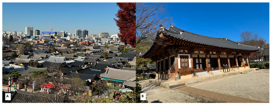
Figure 1.
Views of a Hanok village and a Hanok: (A) Jeonju Hanok Village, the city’s center; (B) Jeonju Dongheon, located within Jeonju Hanok Village, a restored building that served as the local government office during the Joseon Dynasty.
The central government and local authorities are devising various strategies to establish large-scale Hanok complexes, including initiatives to expand the Hanok supply. The number of professionals qualified to construct Hanoks is restricted. Moreover, the quality of construction varies considerably depending on the expertise and qualifications of the construction carpenter [2].
The construction systems and specialized workforce are not adequately prepared for Hanoks, but rather, they conform to existing systems for modern architecture. Due to the historical upheaval since the modern era, architectural education has been centered on Western architecture, and Hanok education is also absent in university architecture departments. Graduates of architecture universities do not understand the Hanok physically, and engineers do not understand the Hanok holistically, resulting in inconsistencies in design and construction [3].
Although architects are exposed to the design market related to Hanoks, they lack basic knowledge about the design and construction of Hanoks, so they excessively rely on the opinions of construction carpenters for planning and constructing the actual wooden parts. Even if architects try to find data on the design of Hanoks, most of them have either anecdotal experiences of building Hanoks or detailed plans of a few Hanok buildings, so the amount of data for designing rather than learning history is insufficient [4]. Rather than faithfully following the format of a ‘heritage Hanok’, modern architects are trying to make modern changes and transformations to it (Figure 2).
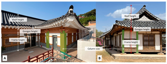
Figure 2.
Comparison of the proportions of Hanoks: (A) Hanok-style concrete building; (B) Traditional Hanok made mainly of wood. Although (A,B) are made of different materials, the column section in (A) is disproportionately larger than (B)’s. In this case, the structural forms are similar, but the proportional parts are not reflected at all. In proportion to the height of the frame and the roof in (A), the roof is designed to be relatively low compared to the height of the frame.
Hanok experts conduct research from various perspectives; studies explore Hanok history and ethos, present comprehensive overviews and construction methods of Hanoks, categorize and explain Hanok-related information through databases, and present Hanok Building Information Modeling (BIM) for design, construction feasibility, and component production. However, no research offers immediate support when designers specializing in modern architecture, lacking knowledge of traditional Hanoks, attempt to design Hanoks [5].
Various local governments have provided standard design drawings for Hanoks by the policy. In the case of Hanok design in Jeollanam-do Province, the utilization of the drawings was very low because the formats of the Hanoks and the standard design drawings were quite different, and there were no guidelines. There must have been a set of proportional systems for Hanoks, but none were institutionalized. In Hanok design, the dimensions of the member sections were still based on experience. Even carpenters have been given the responsibility of section design, rationalizing that it is the carpenters’ conceptual dimensions, but their experience is not uniformly applied [6]. New construction methods suitable for modern life are being developed and popularized. However, from the point of view of the traditional Hanoks, they are different in appearance, and some people believe that they undermine their dignity and value.
The objective of this study is to derive the objective plan, cross-section, and elevation proportions of Hanoks, which will contribute directly to the systematic design and construction of Hanoks. The objective data provide a basis for understanding the traditional Hanoks that are not reliant on subjective experience. The initial data set was analyzed based on the figures of cultural heritage Hanoks that retain traditional features. The data were analyzed by identifying common patterns among the selected Hanoks, categorizing them, and deriving numerical values as ratio values. The study results overcome the limitations of the standard design drawings of Hanoks, typically created with a fixed framework. Additionally, the findings can be utilized as a guideline for systematic Hanok design, allowing designers to exercise creativity and flexibility.
2. Materials and Methods
2.1. Structural Characteristics of Hanoks
Hanoks can be classified based on building composition and structural methods. Fundamentally, a Hanok can be divided into (1) the roof, which constitutes the upper structure and includes linked roof tiles or thatch connected to rafters on the top of Dori; (2) the Gongpo, which is located between the column and the roof and serves a structural function by transferring the roof load received through beams to the columns; and (3) the structural framework, which determines the overall type of Hanok and transfers the upper structure load that is received through the Gongpo to the columns and down to the foundation stone [7] (Figure 3).
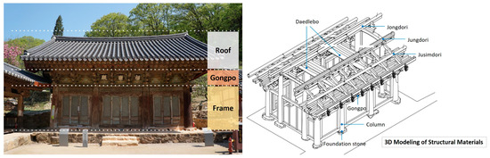
Figure 3.
Structural area of a Hanok (National Treasure Geungnakjeon Hall of Hwaamsa Temple, Wanju) [8]. A Hanok can be classified into a roof, Gongpo, and structural framework. This study used terms based on this classification.
A Kan is a basic Hanok unit that encompasses distance and area concepts. A Kan is the distance between two columns and a space surrounded by four columns. During the Joseon Dynasty, only the number of Kans was initially regulated. However, the size of building components eventually became regulated as house dimensions grew excessively large due to wide column spacing [9]. The distances between columns and the spaces they enclose are inconsistent. This phenomenon is attributable to the proportions of the floor plan being applied to the entire building (Figure 4).
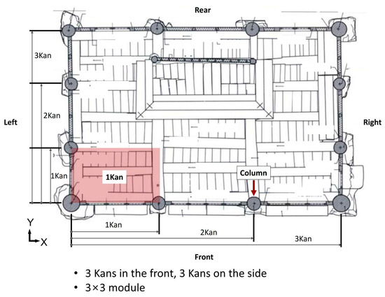
Figure 4.
Attributes of a Hanok floor plan [10]. A Kan is a unit that is used to indicate the dimensions of a floor plan, with its area delineated by columns. It is commonly expressed as 3 Kans in the front and 3 Kans on the side or simply as 3 × 3 when specifying dimensions. In this configuration, the total number of Kans is 9.
Influenced by various factors, such as adapting to modern culture, accommodating regional climate characteristics, and varying floor plan types, distances among primary Kans in Hanoks have evolved. Modernization, driven by changing times, stands out as a critical factor and impacts the dimensions and layout methods of spaces due to shifts in furniture use, fuel methods, and facility systems [9]. In the case of Hanok villages, which are made up of a cluster of old Hanoks, they are designated as a preservation district and are required to maintain the form of the Hanok. However, there are numerous instances of expanding space to adapt to the modern way of life. Focusing on space modules alone can result in an overall loss of balance and disparate proportions in the Hanok’s overall appearance (Figure 5).
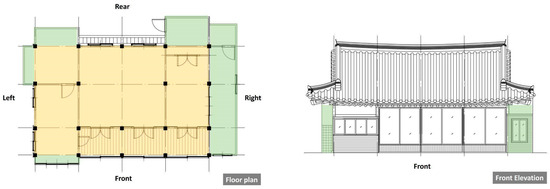
Figure 5.
Space changes in a Hanok [11]. A floor plan and façade of a Hanok. The yellow area represents the originally planned space, whereas the green area indicates the expanded space.
In the spatial composition of a floor plan, its dimensions and distances among columns can vary to suit modern lifestyles. As the floor plan expands, the Hanok’s overall form, which is externally visible, should be considered. There are no fixed values for these proportions because they are based on decisions made by carpenters (Figure 6).
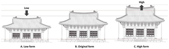
Figure 6.
Hanoks’ façade proportions [12]. These façades compare the proportion of Hanoks. (B) depicts the current façade, whereas (A) shows a form lowered from the original, and (C) illustrates a form heightened from the original.
As the floor plan area of a Hanok expands, its dimensions vary based on the column span distances, which is evident in its cross-sectional structure. Buildings A and B share a comparable structural type with a 5-Ryang. However, they exhibit variances in column span distances. When building A’s proportions are increased to match building B’s maximum height, they exhibit similar forms. This indicates that Hanoks follow certain proportions, and objective data gathered through research are necessary (Figure 7).
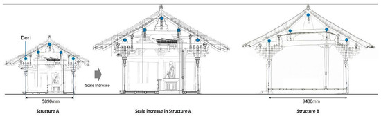
Figure 7.
The ratio of a Hanok’s cross-section [13,14]. The figure compares cross-sectional drawings of Hanoks of varying scales. Structure A and Structure B are constructed in different periods and regions. Despite differences in size, they exhibit a similar ratio in their overall forms. Structure A is the Daegwangjeon Hall of Sinheungsa Temple in Yangsan (Joseon Dynasty; Yangsan, Gyeongsangnam-do), whereas Structure B is the Jeokgwangjeon Hall of Bogyeongsa Temple in Pohang (Silla Dynasty; Pohang, Gyeongsangbuk-do).
2.2. Planning and Design Considerations for Hanok Architecture
Currently, it has become a prevailing practice for clients to initially engage an architect when building a Hanok. Based on their preferences and tastes, clients have diverse desires and often select traditional Hanok exterior designs according to their individual choices. Consequently, contemporary Hanok construction approaches vary, with some seeking to deviate from traditional forms beyond modifying them. Most Hanoks focus on construction methods and the materials that are visible. The central government and local authorities have established Hanok standards that are centered on exterior appearances, with financial support to promote Hanok proliferation. Consequently, the form of Hanoks has been overemphasized [15].
The Act on the Promotion of Hanok and Other Architectural Assets, implemented by the Ministry of Land, Infrastructure and Transport, states that “Hanok refers to wooden structures with columns, beams, and Hanok roof frames, which reflect Korea’s traditional style, including any related buildings.” Further, “Hanok architectural style refers to structures with the form and structure of a Hanok, or those built using its form-related materials and techniques.” However, within these, detailed definitions of what constitutes a Hanok with traditional style are absent.
Architects are the professionals who are tasked with Hanok design and the process of obtaining permissions. Among them, cultural heritage measurement experts specialize in traditional Hanoks; thus, they are the most qualified for new Hanoks. However, these experts focus on preserving the original forms of existing cultural heritage and lack training in integrating modern living facilities and installations such as bathrooms or kitchens into Hanok spaces. Additionally, although general architects are adept at utilizing contemporary construction systems, they are frequently limited when designing Hanoks with in-depth understanding [3].
For traditional Hanoks, construction workforces are vertical and hierarchical, structured around a master builder with subordinates and technicians beneath them. Technicians handle simple construction tasks under the guidance of subordinates, who coordinate the construction under the master builder’s supervision. Master builders oversee technicians and subordinates, with training conducted hierarchically. In contrast, modern architectural production features a horizontal and parallel structure that involves architects, engineers, and technicians. In this system, design and construction are entirely separated, i.e., architects oversee design, whereas engineers oversee construction, and education is conducted individually [16].
The Hanok design process is similar to that of modern architecture, which involves preliminary research, basic planning, basic design, and working drawing planning. However, due to the lack of information on Hanok design, general designers find it challenging to approach Hanok projects. Consequently, Hanok design frequently relies on builders with extensive experience in Hanok construction [17]. In particular, the basic planning stage is challenging because designers struggle to determine the appropriate ratios for changes in cross-sections and façades based on floor plan dimensions (Figure 8).
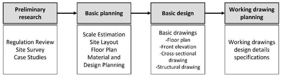
Figure 8.
Current Hanok design process [17]. The figure depicts the Hanok design process, which is similar to the modern architecture process.
In establishing the scale of a Hanok, Kan, the basic unit for a floor plan, is also the basic unit for a cross-section and elevation. The setting of the Kan becomes the concept of setting the position of the columns and composing the space. Moreover, the composition of the Kan depends on the roof type. Moreover, because the Kan is associated with column height, it determines façade proportions. As such, the Kan is a fundamental unit that defines the entire Hanok structure, establishing organic relationships between a floor plan, cross-section, elevation, and roof type [18].
Due to connecting components through cross- and uni-directional joint techniques, a Hanok, as a frame structure, demands that a designer invest a significantly longer amount of time in comprehending the specific parts of a Hanok compared to the time required to create a new building. Documents prepared by carpenters are more akin to the construction process because they emphasize construction-related details such as joints and connections rather than design methodologies.
For architects, accommodating a client’s demands within Hanok architecture is the most challenging aspect. Considering construction costs, collecting examples categorized by dimensions, floor plan types, primary materials, and roof forms is necessary to address this issue. Moreover, detailed construction information is needed during the spatial composition and form planning stages, including structural systems, façades and roof forms, floor and ceiling heights, and electrical and equipment systems planning [17].
2.3. Research Methods
The study flowchart is shown as follows (Figure 9). The research process involved the following stages: selecting research subjects, deriving floor plan ratios and types, deriving cross-sectional structure ratios and types, deriving façade ratios and types, and comprehensive analysis. In the first stage, Hanoks were selected as national treasures or treasure grades from national cultural heritage Hanoks that preserve traditional appearances. At a higher level, these Hanoks are categorized as wooden cultural heritages, and 61 research subjects were chosen based on the criteria relating to their usage, function, and form. From the second to fourth stages, actual measurement drawings maintained by the Cultural Heritage Administration were scrutinized. During the second stage, modules, dimensions, and patterns within Hanok floor plans were analyzed to derive floor plan ratios and types. The third stage involved analyzing modules, dimensions, and patterns within the building framework’s cross-sectional structures and deriving cross-sectional structure ratios and types. During the fourth stage, façade areas were categorized into frame structure, Gongpo, and roof sections, and façade ratios were derived based on categorized roof types. Based on the findings from the second, third, and fourth stages, the fifth stage involved the comprehensive analysis of the relationships between floor plan, cross-sectional structure, and façade ratios.
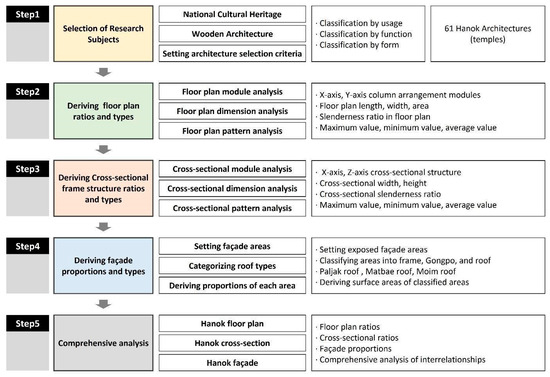
Figure 9.
Research flowchart comprising five stages, detailing the analysis process and specifying the data extracted at individual stages.
Figure 10 presents the detailed experimental methodology of Steps 2 through 4 of the research methodology. The data collection for analysis was based on the measurement and repair reports published by the Cultural Heritage Administration. These documents record specific measurements for columns, beams, and roofs. Attributes typical of Hanoks, such as modules, Gongpo forms, frame structures, and roof types, are extracted for the studied buildings. The floor plan extracts the horizontal and vertical dimensions, column spacing, and column arrangement to show the total area. The column height, Gongpo height, and roof height dimensions are extracted from the sectional plan. Elevations extract frame, Gongpo, and roof surface area figures by identifying areas exposed to the outside. Comparing the extracted numerical data with attributes allowed for looking for regularities to derive a type. The floor plan ratio, section ratio, and elevation ratio are derived for each figure, and the average ratio of the studied Hanoks is derived. The process was repeated by synthesizing the attribute, type, and proportion data, reviewing which data influences the proportions of Hanoks, and extracting the necessary data through the feedback stage. The final step is to optimize the data derived from the comprehensive analysis stage to produce the final result.
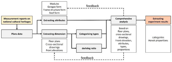
Figure 10.
Experiment method. Each experimental stage is comprehensively demonstrated.
2.4. Study Subjects
Hanoks that are classified as national treasures or treasures from among national cultural heritage that preserve traditional appearances were selected as study subjects. These Hanoks are broadly categorized as wooden cultural heritages. Further, they are classified into historic houses, government offices, palaces, pavilions, temples, Confucian academies, fortresses, and Confucian schools. As of 17 April 2023, there were 256 cultural heritages designated as treasures or national treasures. Out of this number, temples comprised 115, thus accounting for 45% of the total. The study focused on temples because of their significant representation in the classification by purpose. A total of 61 structures were selected as study subjects, considering the feasibility of extracting drawing data and excluding cases with low similarity in building purpose and form, such as structures used as gates, towers, or two-story buildings (Table 1).

Table 1.
List of the studied Hanoks.
2.5. Analysis of Hanok Floor Plans
Hanoks are characterized by their floor plan modules, which have columns positioned at their centers to transmit roof loads to the ground. A Daedlebo, a horizontal structural component, connects above columns and typically spans between the front and rear columns of a Hanok. If a Daedlebo has an extensive y-axis length or a small cross-sectional area, then additional columns are placed inside the floor plan to support it. Data on column positions, arrangements, floor plan modules, and measurements were extracted and diagrammed for each of the 61 Hanok floor plans studied (Figure 11).
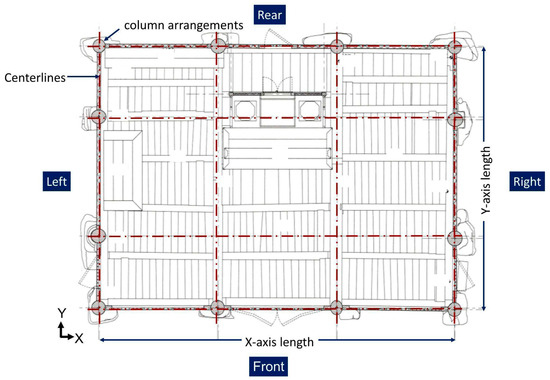
Figure 11.
Extracting floor plan data [19]. A floor plan of one studied Hanok. The circular shapes along the perimeter represent column sections, while the red lines indicate the central axes of the floor plan.
The analysis of column arrangements along the exterior walls in the floor plans demonstrated that the investigated 61 Hanoks comprised six types of modules: 3 × 2, 3 × 3, 3 × 4, 4 × 3, 5 × 3, and 7 × 3. By maintaining a uniform grid module size and aligning the columns along the exterior walls, an expansion of space was observed in the x-axis direction (Figure 12).
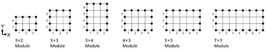
Figure 12.
Hanok module composition based on column arrangements. The grid depicts a module of a Hanok floor plan, with each black dot indicating the position of a column along an exterior wall. The numbers between each column indicate the number of Hanok Kans.
According to the analysis of the Hanok floor plan modules, the 3 × 3 module was the most common at 47.5%, followed by the 3 × 2 module at 24.6% and the 5 × 3 module at 16.4%. Regarding regularities in the floor plan modules, the x-axis ranged from 3 to 7 Kans, whereas the y-axis ranged from 2 to 4 Kans, indicating relatively fewer units than the x-axis (Table 2).
Table 2.
Floor plan modules of the investigated Hanoks (width × length).
Based on the Hanok Kan standard, the 3 × 2 module is relatively small, with 6 Kans. In contrast, the 7 × 3 module is the largest scale with 21 Kans. However, regarding the area, the 4 × 3 module, despite having 12 Kans, exhibited the smallest scale in the average area. Additionally, the 3 × 3 module had a larger maximum area than the 3 × 4 module. No significant differences were observed in the average area, implying that module size and area are not absolute values (Figure 13).
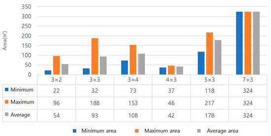
Figure 13.
Comparing the areas (m2) of the investigated Hanok. The floor plan modules are indicated by 3 × 2, 3 × 3, 3 × 4, 4 × 3, 5 × 3, and 7 × 3, and the graphs compare the minimum, maximum, and average area of the Hanoks that belong to each module.
The floor plan modules and their actual measurements were compared. The average length in the x-axis direction ranged from 8980 mm to 11,658 mm for the 3 × 2, 3 × 3, and 3 × 4 modules. The average length of the 5 × 3 and 7 × 3 modules increased with the increase in Kans along the x-axis. In contrast, despite having more columns along the x-axis, the average length of the 4 × 3 module was smaller than those of the 3 × 3 and 3 × 4 modules. This suggests that the number of modules cannot solely determine floor plan areas. Furthermore, the average length along the y-axis shows that the 3 × 4 module is smaller than the 5 × 3 and 7 × 3 modules, despite it having one additional Kan. These measurements indicate that consistent slenderness ratios are evident in floor plans (Table 3).
Table 3.
Average length of the investigated Hanoks (x-axis × y-axis).
2.6. Analysis of Hanok Frame Structures
As Daedlebos span between the front and rear columns, the frame structures of Hanoks can be observed in longitudinal cross-sections. The number of Doris was measured and diagrammed to extract modules for these frame structures. The overall building widths along the y-axis were derived, and the heights were measured and divided into three components: the columns, Gongpos, and the roof. In the roof frame structure, which forms the framework of a Hanok, Doris are the most crucial. Thus, the height of the fifth Dori in Figure 14 is measured. Measuring the height of the Jongdori, the top Dori of the building, is typically measured for documentation purposes.
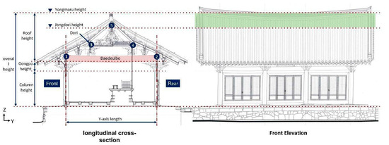
Figure 14.
Hanok cross-section measurement locations [20]. The figure depicts the longitudinal cross-section and façade of a Hanok, with measurement locations indicated. The numbers within the circles in the cross-section represent the numbers of Dori, while the green area on the façade represents the visible area based on the measurement locations in the cross-section.
This study measured the Hanok proportion based on the entire building height from a different perspective. The gap between the Jongdori height and the Yongmaru height within the roof structure can vary when forming and completing the framework. This variation is presumed to be an adjustment to match the roof height to the overall proportions of the Hanok using roofing materials. Therefore, proportions in front elevation drawings were also analyzed (Figure 14).
The longitudinal cross-sections of the studied Hanoks were all diagrammed and categorized. Consequently, they were classified into structures with five, six, seven, and nine Doris, with larger Hanoks tending to have nine Doris. Generally, due to the symmetrical nature of Hanoks, the number of Doris is odd. There are Hanoks with an even number of Doris, specifically six, but these are rare (Figure 15).
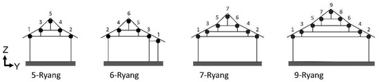
Figure 15.
Cross-sectional frame structures. The figures are cross-sectional drawings. The black dots represent the cross-sections of the Dori, and the numbers above them indicate the numbers of Dori. Based on these numbers, the structures are categorized as 5-, 6-, 7-, or 9-Ryang structures.
Among the 61 Hanoks, the 5-Ryang and 7-Ryang structures were the most common: 44 were 5-Ryang, one was 6-Ryang, 14 were 7-Ryang, and 2 were 9-Ryang. This suggests that 5-Ryang structures are most prevalent in Hanoks, whereas 7-Ryang structures are used for larger buildings (Table 4).
Table 4.
Numbers of Hanoks by frame structure types.
As the side width of a Hanok increases, its Daedlebo’s length and cross-sectional area are affected. The floor plan analysis revealed that the increase in the side width was insignificant, indicating that as the side width increases, the space enlarges, and so does the cross-sectional area of the Daedlebo. Because an extensive cross-sectional area of the Daedlebo can create a sense of oppression in the interior space, certain structures compensate by reducing the Daedlebo’s cross-sectional area and adding additional columns. Examining the average side widths, they increase progressively from 5-Ryang, 6-Ryang, 7-Ryang, to 9-Ryang. However, the maximum side widths demonstrate that the 5-Ryang structures can be comparable in size to the 9-Ryang structures. This indicates that a 9-Ryang structure is not always necessary when increasing the side width (Figure 16).
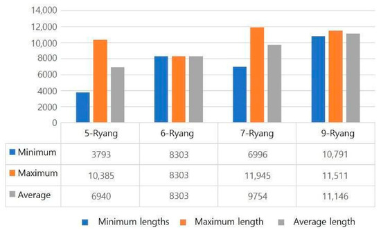
Figure 16.
Side widths of frame structures. These are the measured side widths of the Hanoks, categorized into 5-Ryang, 6-Ryang, 7-Ryang, and 9-Ryang. The minimum, maximum, and average lengths were calculated.
Roof forms and sizes vary among 5-Ryang, 6-Ryang, 7-Ryang, and 9-Ryang structures. The studied Hanoks share similar functions, and the aim was to establish proportional relationships for individual structures. Measurements were categorized based on side width, overall height, and heights of the frame structure, Gongpo, and roof (Figure 17).
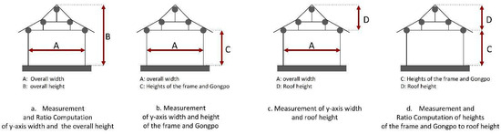
Figure 17.
Locations where Hanok frame structure widths and heights were measured: (a) Measuring the overall proportions in the Hanok; (b) computing the proportions of the body part; (c) identifying the relationship between the side width and the roof height; and (d) computing the proportion between the body part and the roof height.
The side widths and overall heights of the Hanoks were used to calculate slenderness ratios. Based on the A width, the average slenderness ratios were 1:1.20 for 5-Ryang structures, 1:0.89 for 6-Ryang structures, 1:1.08 for 7-Ryang structures, and 1:0.87 for 9-Ryang structures. Although the average width of 9-Ryang structures was the greatest, the maximum heights were smaller than those of 5-Ryang structures (Table 5).
Table 5.
Widths (A) and heights (B) of the overall Hanok cross-sections.
Although 5-Ryang structures exhibited varied ratios ranging between 1:0.9 and 1:1.7, larger structures, such as 7-Ryang or 9-Ryang, had lower slenderness ratios (see Table 6).
Table 6.
Ratios of overall widths and heights of cross-sections based on frame structure classification.
Average slenderness ratios based on A widths and C heights were 1:0.63 for 5-Ryang, 1:0.46 for 6-Ryang, 1:0.56 for 7-Ryang, and 1:0.43 for 9-Ryang structures. The slenderness ratio was lower for 9-Ryang structures (see Table 7).
Table 7.
Hanok cross-sectional widths (A) and heights of frame structures and Gongpos combined (C) of Hanoks.
The slenderness ratios for the 5-Ryang structures varied from 1:0.4 to 1:1.0. In contrast, those for the 7-Ryang structures ranged between 1:0.4 and 1:0.7. The 9-Ryang structures had a slenderness ratio of 1:0.4. The most common slenderness ratios observed were in the order of 1:0.6, 1:0.7, and 1:0.5, in that order (Table 8).
Table 8.
Ratios of cross-sectional widths and the combined heights of frames and Gongpos by frame structures.
The average slenderness ratios of the A widths and the D heights were 1:0.56 for 5-Ryang, 1:0.43 for 6-Ryang, 1:0.53 for 7-Ryang, and 1:0.43 for 9-Ryang. For 6-Ryang and 9-Ryang structures, these ratios were comparable to the ratios of A and D (Table 9).
Table 9.
Cross-section widths (A) and roof heights (D) of the Hanoks.
Slenderness ratios ranged from 1:0.4 to 1:0.8 for the 5-Ryang structures, from 1:0.5 to 1:0.7 for the 7-Ryang structures, and 1:0.4 for the 9-Ryang structures. The most common range for slenderness ratios in the 5-Ryang and 7-Ryang structures was from 1:0.5 to 1:0.6 (see Table 10).
Table 10.
Ratios of frame parts and roof heights by frame structures.
Average slenderness ratios for C and D heights were 1:0.89 for 5-Ryang, 1:0.93 for 6-Ryang, 1:0.95 for 7-Ryang, and 1:1 for 9-Ryang. In 5-Ryang structures, D heights were proportionally lower than C heights, whereas as structures approached 9-Ryang, they showed proportional similarities (see Table 11).
Table 11.
Heights of the frame and Gongpo combined(C) and heights of the roof(D) of Hanoks.
The slenderness ratios ranged from 1:0.4 to 1:1.3 for 5-Ryang structures, 1:0.8 to 1:1.2 for 7-Ryang structures, and 1:1.0 for 9-Ryang structures. In particular, most Hanoks exhibited slenderness ratios between 1:0.8 and 1:1.0 for 5-Ryang and 7-Ryang structures. Across all types of frame structures, the ratio of 1:1 was the most common (Table 12).
Table 12.
Height ratios of frame components and roof components by frame structures.
2.7. Analysis of the Elevation Exposure Area
The roofs are the most prominent components of Hanoks, visually occupying the largest area in their overall appearance. In this study, measured data were obtained through experiments. The exposed areas of individual elements were measured, and their proportions were graphically represented (Figure 18).
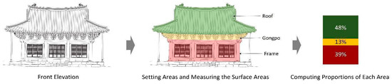
Figure 18.
Dividing the façade into three elements and measuring their surface areas. Individual areas in the front elevation views were assigned specific colors, and their respective surface areas were calculated and graphically represented. This elevation of the data extraction process is Daeungjeon Hall of Daegoksa Temple, Uiseong [12].
Proportions of frames, Gongpo, and roof areas were calculated based on Hanok facades. Similar average proportions were observed between frames, Gongpo, and roof areas in 5-Ryang and 7-Ryang structures, whereas the roof accounted for approximately 58% of the total surface area in 9-Ryang structures. On average, the roof occupied 52.8% of the total surface area, while the frame accounted for 36.3% and the Gongpo for 10.9% (Figure 19 and Figure 20).
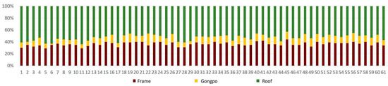
Figure 19.
Surface area proportions of the investigated Hanoks. The figure illustrates the proportional surface areas of frames, Gongpos, and roofs among the 61 studied Hanoks. In the figure, red represents frames, yellow indicates Gongpos, and green denotes roof areas.
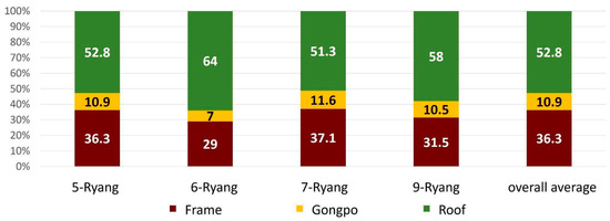
Figure 20.
Surface area proportions of frames, Gongpos, and roofs by frame structures. Average surface area proportions for the 5-Ryang, 6-Ryang, 7-Ryang, and 9-Ryang structures are depicted, with the overall average representing the combined area proportions of all these structures.
3. Results
3.1. Result of Hanok Floor Plan
Based on the floor plan modules, slenderness ratios of the x and y-axes were derived. The y-axis ratio was calculated based on the x-axis value and vice versa, and the values were averaged. Regarding the x-axis width, the average ratios for the 3 × 2, 3 × 3, and 3 × 4 modules ranged from 1:0.64 to 1:0.77, indicating the ratios that were square or did not exceed square. Furthermore, despite an increase of one Kan per side, the increase was not substantial. The ratio of the rise from the 3 × 2 to 3 × 3 modules was +0.09 and +0.04 for the 3 × 3 to 3 × 4 modules. The average ratios for the 4 × 3, 5 × 3, and 7 × 3 modules ranged from 1:0.3 to 1:0.57, indicating a rectangular shape. For these modules, changes in the increase on the sides were calculated based on the y-axis width. The average ratios for the 3 × 2, 3 × 3, and 3 × 4 modules ranged from 1.3:1 to 1.6:1, whereas for the 4 × 3 and 5 × 3 modules, with the increase in front Kans, ranged from 1.8:1 to 2.1:1. In terms of the 7 × 3 module, the ratio was 3.0:1, indicating a rise of 1.5 to 2 times compared to the 3 × 2, 3 × 3, and 3 × 4 modules (Figure 21).
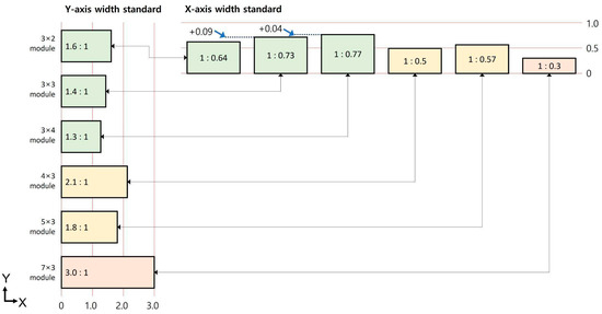
Figure 21.
Floor plan ratios based on the x and y-axes. The y-axis width standard represents the average ratio of the front length based on the side length. In contrast, the x-axis width standard represents the average side length ratio based on the front width.
The increase in the ratios of the Hanok floor plans revealed that the number of Kans increases along the y-axis direction as the floor plan area expands. Sixty-one Hanoks were diagrammed based on a standardized floor plan module arrangement. The arrangements were classified into two main types, Type A and Type B, and a combined type, Type AB. Further, these three basic modules were categorized into structures with and without internal columns and structures that expand along the x-axis direction. Type B was the most common, with 42 Hanoks, followed by Type A with 15, and Type AB with 4. Among these, 20 Hanoks were classified as Type B1 (Figure 22).
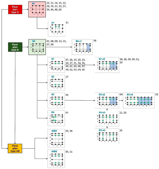
Figure 22.
Categorization of Hanok floor plans. Each black dot indicates a column along a Hanok’s exterior wall, while each green dot represents an internal column. The blue backgrounds in the indicated floor plan demonstrate the form where the number of Kans has increased. A0 and A1 in blue font indicate floor plan categorization, whereas x1 and x2 following them represent the number of Kans added in the x-axis direction. The numbers on the right side of the figure correspond to the investigated Hanoks’ identifiable numbers.
3.2. Result of Hanok Frame Structures
The cross-sections of the investigated Hanoks were categorized into three types: Type A, Type B, and Type C. Typically, these cross-sections exhibit symmetrical characteristics, although asymmetrical 6-Ryang structures were occasionally identified. The 6-Ryang structures have columns on the expanded side lowered while maintaining the 5-Ryang structure format with expanded spatial dimensions. Section Type A0 was the most prevalent, with 23 instances featuring an additional internal column compared to the original format. Section Types A and C included one or two interior columns with wider span spacing. Section Type C featured an internal column close to the structure center for enhanced structural stability (Figure 23).
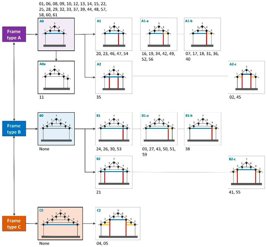
Figure 23.
Categorizing cross-sectional structures (frame types). Hanoks’ cross-sectional structures (frame types) were synthesized and categorized. Blue lines represent the Daedlebos, while yellow lines denote Toetbo, where two beams are connected rather than one beam spanning. Red lines indicate internal columns.
In A1-a, A1-b, B1-a, and B1-b of Figure 23, the Daedlebos are not continuous but are connected by two beams. Vulnerability at the joints in these structures has been identified [21]. Potential future issues should be identified in advance and incorporated into the planning for structural stability [22] (see Figure 24 and Figure 25).
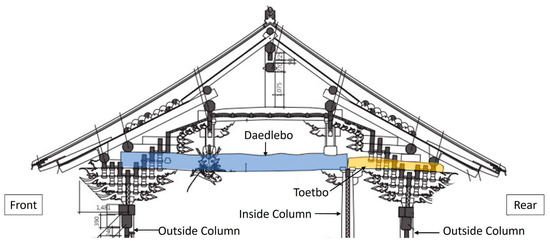
Figure 24.
Cross-sectional view of a Hanok roof component [23]. The figure depicts a cross-sectional view of a Hanok; blue is the Daedlebo, and yellow is the Toetbo.
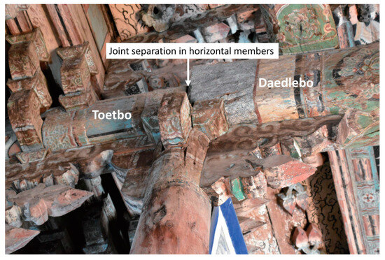
Figure 25.
Joint of a Daedlebo and Toetbo [24]. The figure illustrates a separated joint between a Daedlebo and Toetbo; areas where potential future issues may arise should be identified and incorporated into Hanok planning.
3.3. Façade Result
Gongpo and roof areas had greater variability than frame area changes. Analysis of these areas revealed that Gongpo areas tended to decrease slightly as roof areas increased. Conversely, as roof areas decreased, exposed Gongpo areas increased. Moreover, the combined surface areas of Gongpos and roofs maintained a balanced façade distribution averaging 63.7%. This resulted in a frame-to-roof + Gongpo ratio of 1:1.75 in the area exposed in the studied Hanok façades (Figure 26).
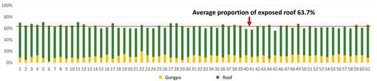
Figure 26.
Proportions of exposed roofs and Gongpos in the studied 61 Hanoks. The figure illustrates the proportional surface areas of Gongpos and roofs across the 61 investigated Hanoks. Yellow represents Gongpo areas, whereas green indicates roof areas.
3.4. Comprehensive Analysis
The initial stage in planning and designing a Hanok involves modularly configuring the floor space. Through analysis of floor plan modules, categories of Plan Types A, B, and AB were identified. Hanoks expand spatially by adding columns along the x-axis rather than the y-axis, resulting in a rectangular shape.
The second stage involves the cross-sectional structure, categorized into 5-Ryang, 6-Ryang, 7-Ryang, and 9-Ryang types, with 5-Ryang and 7-Ryang being the most common. As structures approach 9-Ryang, roof structures become increasingly dense, and the floor plan widens in the y-axis direction. However, widening the floor plan in the y-axis makes it challenging for the Daedlebo to support the structure, necessitating the addition of an interior column to support the Daedlebo. Section types are classified based on whether one or two columns are added. However, adding a column can impose spatial limitations. To avoid adding a column, the cross-sectional area of the Daedlebo needs to be increased. Section Type C2 provides a more stable structure compared to Section Type C0 in Figure 27.
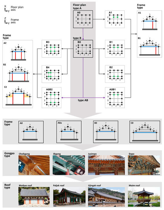
Figure 27.
Comprehensive Hanok floor plan, cross-section, and façade planning. The figure depicts the results of investigating types in floor plans, cross-sections, and façades (Gongpos and roofs).
The third stage involves the configuration of Gongpos. Gongpos not only transmit the roof load to columns but also contribute to the aesthetic appearance of the external structure. Gongpos can be categorized into Choikgong, Iikgong, Jusimpo, and Dapo, which are the most elaborate. When selecting a Gongpo style, its proportionate height, in relation to the overall building height, should be considered.
The fourth stage involves achieving an optimized ratio for Hanoks. While the floor plan and cross-sectional structures may be similar, the choice of roof shape significantly alters the appearance of a Hanok. Balancing the ratio between the roof and Gongpo areas is crucial, and this balance should be adjusted while maintaining the cross-sectional ratio. Particularly, the interdependent changes in the exposed roof and Gongpo areas indicate that when the exposed roof area is extensive, the overall façade proportion should be adjusted by reducing the exposed Gongpo area (Figure 27).
4. Discussion and Conclusions
With growing interest in Hanoks, an eco-friendly architecture, due to environmental concerns, there has been a sudden surge in demand for them. However, The most common type of modern residential architecture comprises uniform concrete apartments, which also raises the proportion of contemporary architects. The lack of systematic education on Hanoks prompted government-led initiatives to promote Hanok education. Due to the time needed to acquire skills, there is a heavy reliance on craftsmen’s (carpenters’) opinions in Hanok construction. One of the major challenges arises from planning and constructing Hanoks when their traditional practices are yet unconsolidated, leading to compromised structural quality. To improve subsequent constructions, craftsmen draw upon their previous experiences from Hanoks. However, these insights often rely on subjective rather than objective data.
Structures can resemble traditional Hanoks by using similar materials, but they can fail to capture the inherent beauty of the original Hanoks. Both modern and traditional architectures have their beauty, which includes specific ratios. Objective data were obtained by analyzing the types and ratios in traditional Hanoks, which are the buildings built in the traditional Korean styles according to the official definitions. Although the Hanoks that were studied varied in terms of their construction period, scale, designer, and constructor, the analysis of their floor plans, cross-sections, and façades revealed the existence of consistent ratios.
The analysis of 61 Hanok floor plan modules revealed similarities stemming from two basic modules, Plan Type A and Plan Type B. Variations in floor plans arise due to internal columns and spatial expansion. Internal columns are placed considering the length or cross-sectional area of the Daedlebo, which connects the front and rear columns. While spatial usage can increase when internal columns are absent, these columns can also serve as benchmarks for distinguishing spaces. Additionally, spatial expansion typically involves adding Kans along the x-axis direction.
Furthermore, the analysis of the floor plan ratios revealed that the 3 × 2, 3 × 3, and 3 × 4 modules had ratios ranging from 1:0.64 to 1:0.77 based on the widths along the x-axis. While the y-axis increased by one Kan, the rate of increase was lower, at +0.09 and +0.04. Although the floor plans appeared almost square, they maintained rectangular shapes. The 4 × 3 and 5 × 3 modules had ratios of 1.8:1 to 2.1:1, and the 7 × 3 module resulted in a ratio of 3:1 based on the width along the y-axis.
Moreover, after analyzing 61 Hanoks, the cross-sectional modules were categorized into three types: Section Type A, Section Type B, and Section Type C. These types are referred to as 5-Ryang, 6-Ryang, 7-Ryang, and 9-Ryang Hanok structures, with 6-Ryang structures derived from 5-Ryang structures. The cross-sectional structure varies slightly when internal columns are placed based on the front and rear span lengths. However, the 5-Ryang, 6-Ryang, 7-Ryang, and 9-Ryang structures share similar structural patterns, enabling the categorization of cross-sections.
In addition, the analysis of cross-sectional ratios revealed that the average slenderness ratios of the overall height to the front and rear span distances were 1:1.2, 1:1.08, and 1:0.87 for 5-Ryang, 7-Ryang, and 9-Ryang structures, respectively, indicating a decrease in overall height with the increase in scale. Moreover, the average slenderness ratios of the roof height to the combined height of the frame and Gongpo, measured from where the roof was composed, were 1:0.89, 1:0.95, and 1:1 for 5-Ryang, 7-Ryang, and 9-Ryang, respectively, showing minimal variations in these ratios.
Fifth, the façade completes the final form derived from the cross-sectional structure. The average exposed surface area proportions of the frame, Gongpo, and roof were 36.3%, 10.9%, and 52.8%, respectively. Roofs are visually prominent in Hanoks due to their high proportions, which was confirmed with objective data in this study.
Finally, it was discovered that Gongpos, which enhance the beauty of Hanoks, were found to have a strong relationship with roof ratio. An increase in the exposed surface area of roofs led to a decrease in Gongpos’ exposed surface area ratio, and vice versa. The combined proportion of their exposed surface areas fell within 63.7%. Consequently, the ratio of the frame area to the sum of the roof and Gongpo areas exposed in façades was 1:1.75.
The results of this study provide a basis for maintaining the proportions of traditional Hanoks even when changes in space and height occur in Hanok design. As this study confirms that the proportional system of Hanoks exists even if the buildings under study are different in time and place, it can be a new research method to derive the proportional system of Hanoks. In addition, it can be a reference for designers in the process of verifying and modifying design drawings, and it is significant in providing a method and direction for building a new dataset for Hanok design.
However, there are limitations in applying the results to Hanoks with different uses and the cross-sectional area ratio of members of Hanoks with changes in scale, as the results were derived from the temple architecture scope. In future research, it is necessary to apply the change in the cross-sectional area of Hanok members according to the increase and decrease of the overall proportion of the Hanok. The characteristic of Hanoks is that small members are gathered and joined together, and as the scale of the building increases, the cross-sectional area of structural members, such as columns and beams, changes. If the floor span is adjusted to be unreasonably large, the cross-sectional area of the beam increases, which may provide structural stability but creates a sense of visual imposition. It is necessary to derive a correlation between the dimensions of Hanok members and apply it to Hanok design and the existing BIM Hanok system.
Funding
This research received no external funding.
Data Availability Statement
The data presented in this study are available in this article.
Conflicts of Interest
The author declares no conflicts of interest.
References
- Ahn, E.Y. Intelligent architectural design module for process automation of Hanok constructions. J. Korea Multimed. Soc. 2012, 15, 1156–1164. [Google Scholar] [CrossRef][Green Version]
- Lim, S.H. Modular Hanok HARU. J. Archit. Inst. Korea 2016, 60, 57–60. [Google Scholar]
- Chang, M.H. A Study on the Educational System for the Professional Manpower Training of Traditional Housing, Hanok; The Graduate School Yonsei University: Seoul, Republic of Korea, 2013; pp. 1–230. [Google Scholar]
- Jeon, B.H.; Kim, H.N. Building a Comprehensive Database for the Popularization of Hanok; The Korean Housing Association: Seoul, Republic of Korea, 2011; Volume 6, pp. 6–14. [Google Scholar]
- Ma, S.B. A study on design standards of Hanok design. J. Archit. Inst. Korea 2013, 29, 183–194. [Google Scholar]
- Kim, J.U. A Study on the Han-Ok Standard Drawing and it’s Improvement. J. Archit. Inst. Korea 2012, 28, 219–228. [Google Scholar]
- Park, B.K. A Study on Plants for Improving the Utilization of BIM in the Early Stage of Han-Ok Design; The Graduate School Kangwon National University: Chuncheon, Republic of Korea, 2013; p. 22. [Google Scholar]
- Korea Heritage Service. Precision Measurement Report on Geungnakjeon Hall of Hwaamsa Temple, Wanju; Korea Heritage Service: Daejeon, Republic of Korea, 2004; p. 339.
- Cho, Y.M.; Kim, W.J. A study on modular coordination about the new Korea traditional housing. J. Archit. Inst. Korea 2012, 28, 183–190. [Google Scholar]
- Korea Heritage Service. Disassembly and Repair Report on Daeungjeon Hall of Yulgoksa Temple, Sancheong; Korea Heritage Service: Daejeon, Republic of Korea, 2003; p. 321.
- Jeonju City. Jeonju Hanok Village Database (DB) Construction Project; Jeonju City: Jeonju, Republic of Korea, 2008; pp. 186–188. [Google Scholar]
- Korea Heritage Service. Precision Measurement Report on Daeungjeon Hall of Daegoksa Temple, Uiseong; Korea Heritage Service: Daejeon, Republic of Korea, 2014; pp. 324–325.
- Korea Heritage Service. Precision Measurement Report on Jeokgwangjeon Hall of Bogyeongsa Temple, Pohang; Korea Heritage Service: Daejeon, Republic of Korea, 2017; p. 328.
- Korea Heritage Service. Precision Measurement Report on Daegwangjeon Hall of Sinheungsa Temple, Yangsan; Korea Heritage Service: Daejeon, Republic of Korea, 2012; p. 281.
- Kim, W.C. The accumulation of experience ‘Hanok’s conceptual design. J. Archit. Inst. Korea 2016, 60, 65–67. [Google Scholar] [CrossRef]
- Lee, K.M.; Shin, C.H.; Choi, E.S. Study on Education and Certification System for Hanok Construction Professionals; Architecture & Urban Research Institute: Sejong, Republic of Korea, 2013; pp. 1–240. [Google Scholar]
- Lee, J.O.; Han, J.A.; Han, P.W. Study on defining the Hanok design process and required design information. J. Archit. Hist. 2013, 22, 34–42. [Google Scholar]
- Kim, D.K. A study on technique and application of Hanok design and construction. J. Archit. Hist. 2008, 17, 13565–13572. [Google Scholar]
- Korea Heritage Service. Measurement Report on Daeungjeon Hall of Gaesimsa Temple, Seosan; Korea Heritage Service: Daejeon, Republic of Korea, 2001; p. 364.
- Korea Heritage Service. Measurement Report on Geungnakjeon Hall of Muwisa Temple, Gangjin (Illustration); Korea Heritage Service: Daejeon, Republic of Korea, 2004; pp. 15–19.
- Shin, B.U. Development of YOLOv8 and segment anything model algorithm-based Hanok object detection model for sustainable maintenance of Hanok architecture. Sustainability 2024, 16, 3775. [Google Scholar] [CrossRef]
- Shin, B.U. A study on predicting the movement of columns in Hanok architecture using the UMAP and DBSCAN algorithms. Buildings 2024, 14, 277. [Google Scholar] [CrossRef]
- Korea Heritage Service. Precision Measurement Report on Daeungbojeon Hall of Naesosa Temple, Buan; Korea Heritage Service: Daejeon, Republic of Korea, 2012; pp. 338–339.
- National Research Institute of Cultural Heritage. Periodic Survey Report of National Architectural Heritage; National Research Institute of Cultural Heritage: Daejeon, Republic of Korea, 2021; Volume 3, p. 150. [Google Scholar]


Disclaimer/Publisher’s Note: The statements, opinions and data contained in all publications are solely those of the individual author(s) and contributor(s) and not of MDPI and/or the editor(s). MDPI and/or the editor(s) disclaim responsibility for any injury to people or property resulting from any ideas, methods, instructions or products referred to in the content. |
© 2024 by the author. Licensee MDPI, Basel, Switzerland. This article is an open access article distributed under the terms and conditions of the Creative Commons Attribution (CC BY) license (https://creativecommons.org/licenses/by/4.0/).