Article

Research on Monitoring Technology for Frame Piers of Continuous Box-Girder Bridges Constructed by the Cantilever Method

1
Guangzhou Highway Co., Ltd., Guangzhou 510000, China
2
Department of Civil Engineering, Faculty of Civil Engineering and Transport, South China University of Technology, Guangzhou 510000, China
3
Guangzhou Yuedong Country Garden Investment Co., Ltd., Meizhou 514000, China
*
Author to whom correspondence should be addressed.
Buildings 2024, 14(8), 2409; https://doi.org/10.3390/buildings14082409
Submission received: 10 April 2024 / Revised: 9 July 2024 / Accepted: 27 July 2024 / Published: 4 August 2024
(This article belongs to the Section Building Structures)

Abstract

:
This paper focuses on the analysis of the stress state of a large-span frame pier-continuous box girder bridge with pier crossbeams anchored by pier crossbeams on the main pier of the Guangfo-Zhao Expressway. The bridge is constructed by the cantilever method, and a refined finite element model of the entire bridge is established using the finite element software Midas/FEA to analyze the stress state of the frame pier during the cantilever construction process. It is found that under the possible combined action of an unbalanced load during construction, the torsional resistance of the frame pier crossbeam does not meet the requirements of the design code. In order to eliminate the torsion of the frame piers, counterweights were used to monitor the frame piers during the construction of the box girders. In this paper, the theoretical calculation formula of the inclination angle of the end section of the frame pier crossbeam with the change of unbalanced bending moment, the calculation formula of the relationship between the horizontal displacement of the frame pier and the unbalanced bending moment, and the calculation formula corresponding to the relationship with the water tank counterweight are derived using the structural mechanics method. Two monitoring methods for the frame pier are proposed. In the construction monitoring of the bridge, the numerical fitting formula obtained by finite element numerical analysis calculation is compared with the calculated formula obtained by substituting the design parameters of the frame pier into the theoretical formula. The basic constants in both formulas are basically equal, verifying the correctness of the monitoring calculation formula proposed in this paper for the torsional resistance of the frame pier crossbeam. The applicability of the two monitoring methods is also compared and analyzed. This paper takes the main pier of Chaoyang overpass’s mainline bridge as the engineering background, which adopts the framework pier with a large-span prestressed concrete continuous box girder bridge. It analyzes the torsional state of the beam of the framework pier during the bridge construction process and conducts research on the construction monitoring of the framework pier crossbeam, providing valuable references for the construction monitoring of framework pier crossbeams in the construction of large-span framework pier continuous bridges in the future. The research results of this paper can provide assistance for the construction monitoring of similar projects. This paper’s innovation primarily resides in employing structural mechanics methods to compute the torsion of frame piers. On this basis, a simplified beam torsion calculation formula is proposed to strengthen its practical application in construction monitoring. The findings of this paper can help in the construction monitoring of similar projects.

1. Introduction

In recent years, to alleviate urban traffic congestion problems, numerous viaducts, crossings, and overpasses have been constructed [1,2,3]. These bridges are often built on existing urban road arteries, and the piers should be placed on both sides of the road or on the barrier to meet the needs of the road traffic under the bridge [4,5,6]. Traditional bridge piers have been modified to form frame piers. The current form of frame piers for bridges can be broadly classified into two types, i.e., independent frame piers and frame piers where the main girder is cemented to the abutment cross girder (i.e., pier-beam cementation). Independent frame piers are typically used for small to medium-span bridges and are not limited by bridge deck elevation, commonly found on elevated bridges. The frame pier with pier-beam consolidation is used for large and medium-span bridges with limited deck elevation and is generally used more often in cross-line bridges. With the development of economic construction, smooth urban traffic has become increasingly important, leading to an increase in road improvement and expansion projects. To obtain more space under bridges, the construction of large-span frame piers for continuous box girder bridges crossing intersections is expected to grow.
Large-span continuous box girder bridges with frame piers are a recently developed novel bridge type. There is relatively little research on the construction monitoring technology for frame piers and continuous box girders, but there is more research on the construction monitoring technology for large-span continuous box girder bridges domestically [7,8,9]. This paper takes the large-span prestressed concrete continuous box girder bridge with frame piers as the engineering background of the Chaoyang overpass mainline bridge. It analyzes the torsional state of the frame pier crossbeam during the bridge construction process and conducts research on the construction monitoring of the frame pier crossbeam, providing valuable reference for the construction and monitoring of frame pier crossbeams in future large-span frame pier continuous bridge projects.
The innovation of this paper mainly lies in the utilization of structural mechanics methods to calculate the torsion of frame piers. Based on this, a simplified calculation formula for beam torsion is proposed, facilitating its application in construction monitoring. Additionally, two methods for monitoring frame piers are introduced. The article verifies that the theoretical formula derived for monitoring calculations of the framework pier crossbeam is correct, easy to use, requires minimal computational effort, and holds value for widespread application.

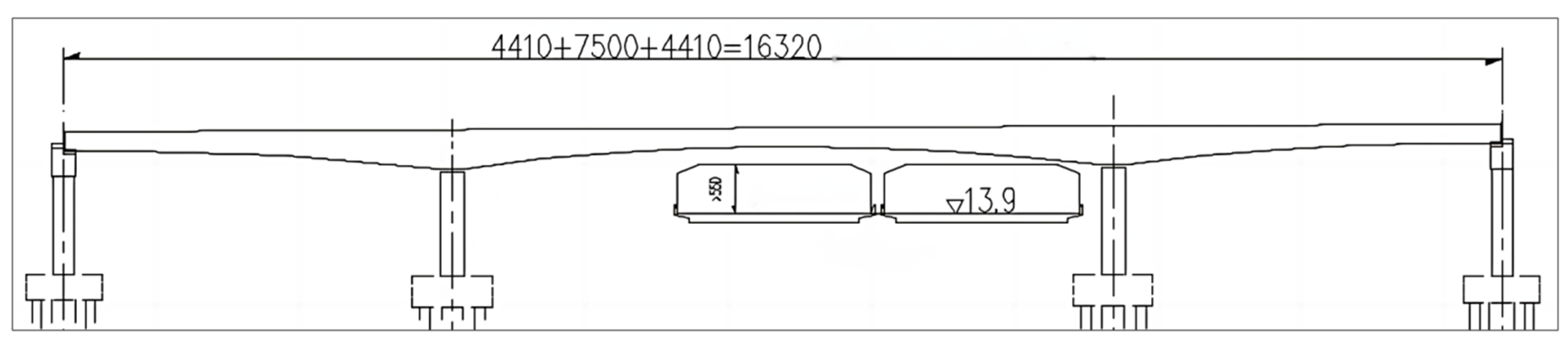
2. Overview of the Project

Chaoyang overpass mainline bridge is a prestressed concrete continuous box girder bridge with a total length of 163.2 m and a span combination of (44.1 + 75 + 44.1) m. The superstructure box girder is a single box with two chambers. The height of the midspan section beam is 2.2 m, and the height of the fulcrum section beam is 4.7 m. Variable section beam height varies by quadratic parabola. The roof of the box girder is 16.25 m wide, with the chamber width at 9.25 m and a cantilever length of 3.5 m for both flanges. The roof’s thickness is 30 cm, and the girder’s thickness varies in three sections: beams 0# to 5# have a thickness of 65 cm, beams 6# to 7# undergo a linear transition, and beams 8# to 9# have a thickness of 45 cm, with the cast-in-place beam ranging from 45 cm to 65 cm. The middle floor thickness of the box girder span is 30 cm, the root floor thickness is 120 cm, and the thickness of the base plate varies according to a quadratic parabola. The concrete grade is C50.The bridge layout is shown in Figure 1, the length unit is ‘cm’, and the unit of the water surface elevation is ‘m’.
The main pier adopts a frame pier design, with the beam being a prestressed concrete rectangular beam measuring 4.7 m in height, 3.0 m in width, and 25.0 m in length. The pier is of rectangular section, with a transverse width of 2.0 m and varying linearly, a pier top width of 3.0 m, a pier bottom width of 3.5 m, and a pier height of 14.6 m. Basin rubber support is provided between the beam and the pier.
The box girder beam and the frame pier crossbeam are consolidated into one. One end beam of the frame pier crossbeam is 10.6 m long, and the other end beam is 5.15 m long.
Two bored piles with a diameter of 2.0 m are used, and the distance between piles is 4.0 m.
The bridge is constructed using the symmetrical cantilever casting method. The whole bridge is divided into 12 kinds of beam sections, which are 5.6 m (side span cast-in-place section) + 2.0 m (side span closure section) + 3 × 4 m + 3 × 3.5 m + 33 m (9 suspended cast sections) + 10.0 m (0# block) + 3 × 4 m + 3 × 3.5 m + 33 m (9 suspended cast sections) + 2.0 m (midspan closure section). The 0# block beam section is constructed by cast-in-place support; the 1 #–9 # beam section is constructed by hanging basket cantilevers; the closed section is constructed by hangers; and the cast-in-place section is constructed by brackets.
During the construction process of cantilever pouring, the frame beams and the piers are temporarily consolidated in the longitudinal direction. The form of temporary consolidation is to set temporary support piers on both sides of the permanent support between the pier crossbeam and the pier. Each temporary support pier adopts 32 finely rolled thread steel bars of 32 mm diameter to anchor into the pier and the beam, respectively.

3. Analysis of Pier and Beam Torsion during Cantilever Construction

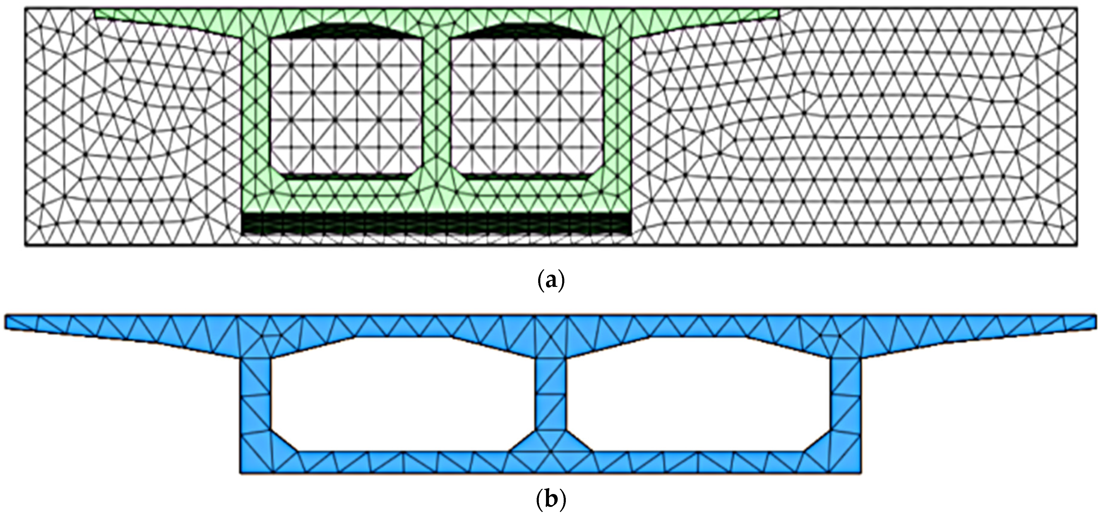
3.1. Refinement of Finite Element Model Establishment [10]

Using Midas/FEA finite element software, the solid structure of the bridge was modeled by meshing solid cells. Mesh delineation using automatic generation of tetrahedral solid meshes of smoothly varying dimensions, with a mesh size selected as 0.5 m. In Midas/FEA, an implantation method was adopted for the treatment of prestressed tendons. Instead of modeling the reinforcement with a specific cell, this method uses the addition of the stiffness of the reinforcement to the parent cell and is able to take into account the various prestressing losses. Therefore, the linear conductor coordinates of each prestressing steel bundle are connected according to the position given in the design drawings, and then the prestressing steel bundles are embedded in the solid cell model. The refined simulation finite element overall computational model is depicted in Figure 2, and the mesh division of key sections is shown in Figure 3. And more details are shown in Table 1.
In the analysis and calculation, according to the construction technology, construction process, and construction progress of the bridge, the whole bridge is divided into 39 construction stages. The construction days and work contents of each construction stage are shown in Table 2.

3.2. Analysis of Torsion of Pier Crossbeam during Construction of Symmetrical Cantilever of Box Girder

When constructing to the maximum cantilever state, various combinations of unbalanced load effects may occur, making the pier girder experience the most unfavorable loading conditions. It is necessary to refine the finite element model of this construction stage of the pier crossbeam under torsion analysis and calculation. In the condition of the maximum cantilever construction stage, the unbalanced loads include:
(1)
A deviation in the self-weight of the box girder sections on both sides of the cantilever, with a deviation range of ±4%;
(2)
Placement of tools and materials on the beam, with an evenly distributed load of 8 kN/m acting on one side of the cantilever;
(3)
Deviation in the weight of the hanging basket and formwork, with a deviation coefficient of 1.2 on one end and 0.8 on the other;
(4)
Unsynchronized removal of hanging baskets, with one end completely dismantled and the other end dismantled by 50%;
(5)
Unsynchronized construction of the last cast box girder section, with concrete poured 100% on one side and 50% on the other side;
(6)
Vertical wind load: considering the asymmetric static wind load acting on both sides of the cantilever of the T-girder, with an asymmetry coefficient of 0.5. Calculate the equivalent static wind load on the main girder according to the “Code for Wind Resistance Design of Highway Bridges”.
The maximum unbalanced bending moment resulting from the above unbalanced loads is calculated to be 48,515.2 kN·m.
The effect of unbalanced loads is realized in the finite element calculation model in the following way. The simulation of the deviation of the self-weight of the beam sections on both sides is achieved by modifying the material capacity on both sides; the stacking of the tool material on one side of the cantilever is achieved by applying a face pressure of 0.49 kPa on one side; the deviation of the hanging basket and formwork is achieved by applying a concentrated force of 840 kN on one side of the cantilever end and 560 kN on the other side of the cantilever end; and the unsynchronized construction of the last overhanging block is achieved by modeling only half a section on one side to participate in the calculation. The asymmetric vertical wind load was achieved by applying a surface pressure of 0.23 kPa on one side.
Under the action of an unbalanced load combination, the main tensile stress cloud of the pier transverse beam obtained from the computational analysis is shown in Figure 4.
As can be seen from the stress cloud diagram of Figure 3, the frame pier crossbeam is twisted under the action of the unbalanced bending moment, and the maximum main tensile stress value appears on the sides of both ends of the pier crossbeam. In Figure 3b, the maximum main tensile stress near the consolidation area of the beam and the box girder is 1.91 MPa, and the main tensile stress value in other positions is small, all within 0.6 MPa. In Figure 3c, the main tensile stress in the region close to the temporary consolidation piers at both ends is a maximum of 5.13 MPa, which has exceeded the designed tensile strength value of C50 concrete. It can be seen that the torsion resistance of the frame pier cross beam does not meet the requirements of the design specification during the construction process.

4. Research on Torsion Monitoring Technology of Pier Crossbeam during Cantilever Construction

To address the issue of potential torsional stress on the girder due to unbalanced loads during construction, two approaches can be taken: modifying the design of the pier girder to enhance its torsional resistance, or applying balancing counterweights during construction and monitoring pier girder deformation to eliminate unbalanced bending moments. Modifying the design of the pier girder would result in project changes and increased costs, which is not desirable. Therefore, it is necessary to study the torsion monitoring technology during the construction of frame pier crossbeams to eliminate the effect of unbalanced loads by means of construction monitoring.
Construction monitoring techniques generally involve both monitoring calculations and monitoring methods. Typically, for complex bridge structures, finite element models are used in monitoring calculations to analyze the structural stress state and obtain corresponding monitoring control parameters. Therefore, finding a simple calculation method or formula for monitoring the calculations of the pier girder is the focus of this study.

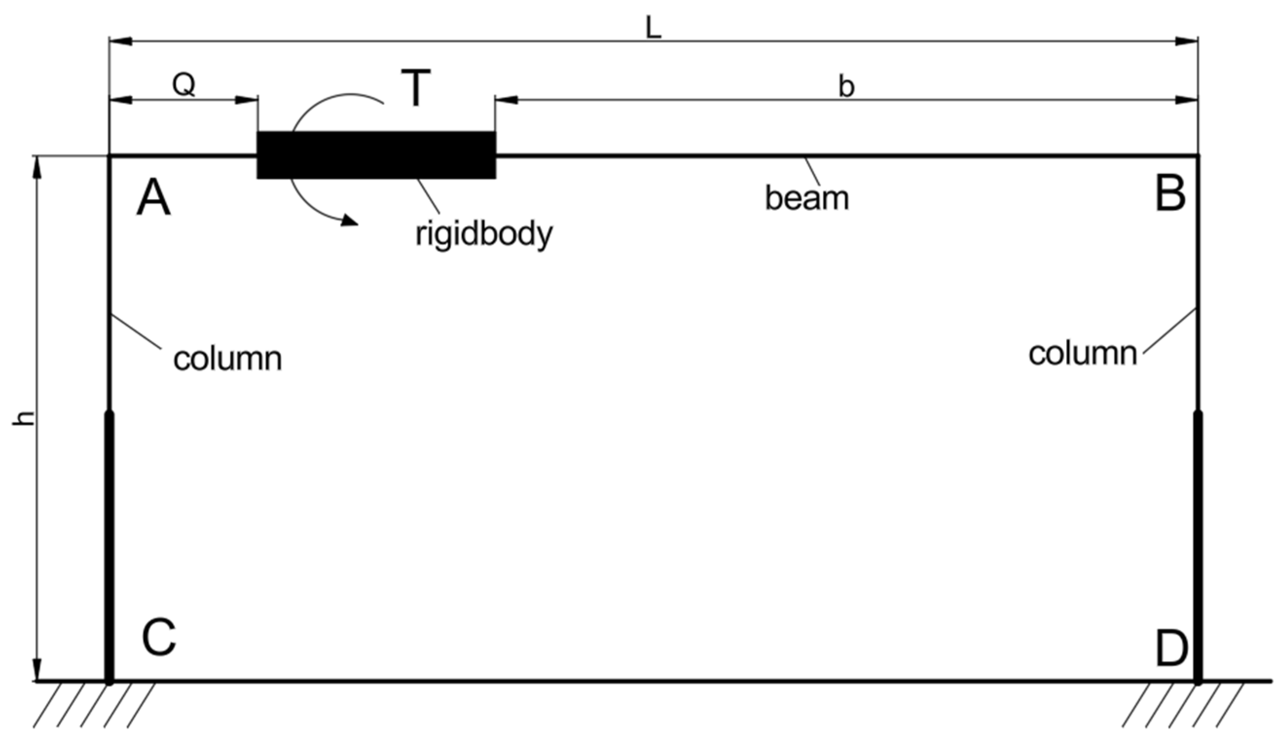
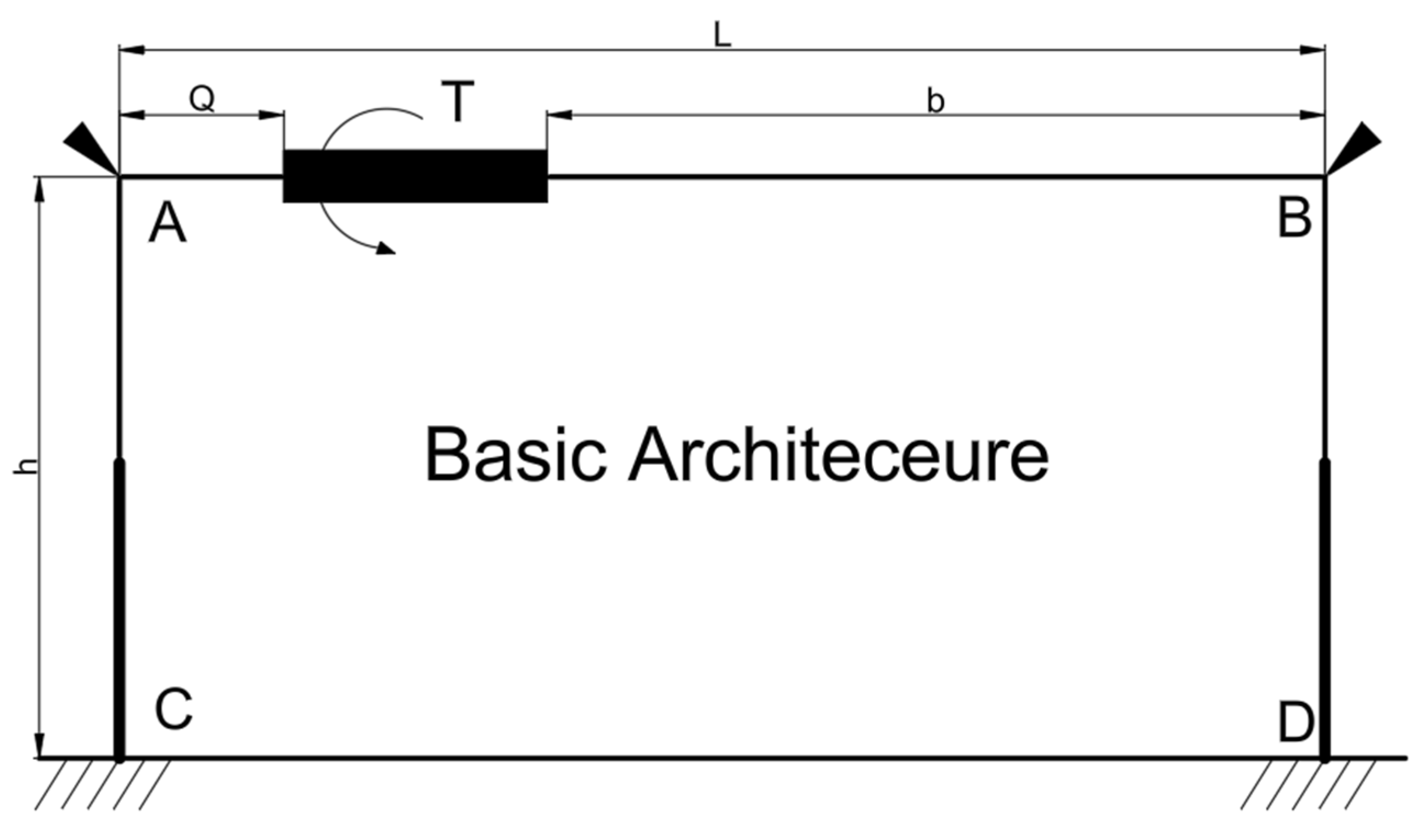
4.1. Theoretical Formula for Torsion Monitoring Calculation of Pier Crossbeam

During the construction process of bridge cantilever symmetrical construction, there may be asymmetric loads acting (such as asynchronous concrete pouring on both sides of the cantilever), which results in unbalanced bending moments on the sections of the box beams at the fulcrum on the pier. Since the frame pier of the frame pier bridge is fixed to the box girder, the action of this unbalanced bending moment will cause torsional stress on the pier girder, leading to lateral tilting of the pier girder and bending deformation of the frame piers. Therefore, the monitoring calculation of the pier girder aims to establish the relationship between the monitoring control parameters corresponding to the torsional stress state of the girder under the action of unbalanced bending moments.
The unbalanced bending moments that may exist during bridge construction cause torsional stress on the pier girder. Therefore, the action of this unbalanced bending moment is equivalent to applying a torque to the pier girder. In order to derive the theoretical formula for the relationship between the unbalanced bending moment (i.e., torque) and the deformation of the pier girder, this paper separates the frame pier from the continuous box girder bridge, treating the fixed area of the box girder and girder under the action of the unbalanced bending moment (i.e., torque) T as a rigid body, forming the following theoretical calculation schematic (see Figure 5).
In Figure 4, l is the span of the beam, h is the height of the pier, a is the distance between the rigid body of the beam and the end A, and b is the distance from the rigid body of the beam to the end B.
Using the theoretical calculation method of structural mechanics [11] for solving the superstatic structure, the consolidated stiffening arms are applied to the nodes of the frame piers to form the basic system of the structure, as shown in Figure 6.
First, calculate the torques Ta and Tb at both ends of the fixed beam. From the static equilibrium equation:
T a + T b = T
Then use the deformation co-ordination condition, where the sum of the rotation angles produced by the B end at T and Ta is zero, then:
ψ b = T b G J T a a + b G J = 0
Ta is solved, then substituted into the equilibrium equation to obtain Tb:
T a = T b a + b                         T b = T a ( a + b )
Under the action of T, the corresponding torsion angles generated at the A and B ends ψa, ψb for:
ψ a = T a G J                           ψ b = T b G J
There, GJ is the torsional stiffness of the cross beam.
Release the consolidated rigid arm to replace the torques Ta and Tb at the tip of the pier, and then the deflection fa and inclination βa of the A end of the variable section pier can be obtained, as can the deflection fb and inclination βb of the B end [12,13,14,15,16,17,18].
The transverse width of the AC variable section pier is unchanged, and the variable width of the longitudinal width is linear. The transverse width of the AC pier should be set as bz, the longitudinal width at A end hz1, and the longitudinal width at C end hz2. Remove the AC pier from the frame pier with the top consolidated rigid arm release for torque Ta, the calculation diagram for the pier is shown in Figure 7 [19,20,21,22,23].
Considering that the widening of the longitudinal width of the pier is linear, the linear function of the longitudinal width is:
h z x = ( h z 2 h z 1 ) x h + h z 1
According to the diagram multiplication of structural mechanics, the displacement and inclination of the end of the cantilever are:
f a = 0 h M M ¯ E I d x = 0 h T a x E I x d x  
β a = 0 h M M ¯ E I d x = 0 h T a E I ( x ) d x
To integrate and simplify the above formula, which can be obtained:
f a = 6 T a h 2 E b z h z 1 h z 2 2
β a = 6 T a h ( h z 1 + h z 2 ) E b z h z 1 2 h z 2 2
In the above equation, E is the elastic modulus of the pier.
If the pier is of equal section, set hz1 = hz2, Formulas (8) and (9) can be obtained:
f a = 6 T a h 2 E b z h z 2 3 = T a h 2 2 E I z                                   β a = 12 T a h E b z h z 2 3 = T a h E I z
EIz is the bending stiffness of the pier.
Considering the torsional effect on the pier girder, it will cause the pier girder to undergo torsional lateral tilting, which in turn leads to bending deformation of the piers. Therefore, the angle of inclination of the frame pier crossbeam is the superposition of the angle of inclination of the frame pier at the top, where bending occurs, and the angle of twist at the end of the frame pier crossbeam [24,25,26,27,28]. Thus, the inclination angle φa on the A-end pier girder is the superposition of the girder’s rotation angle and the pier’s inclination angle, that is:
φ a = ψ a + β a = C a T
In the formula, Ca is the inclination angle flexibility coefficient of the beam. The calculation formula is:
C a = 6 b h ( h z 1 + h z 2 ) E b z h z 1 2 h z 2 2 ( a + b ) + a G J
Similarly, the deflection fb and the inclination βb of the B end pier can be obtained. The inclination angle φb on the cross beam of the frame pier is:
φ b = ψ b + β b = C b T
C b = 6 a h ( h z 1 + h z 2 ) E b z h z 1 2 h z 2 2 ( a + b ) + b G J
Equations (11)–(14) are the calculation formulas for the unbalanced bending moment and tilt angle of the end of the frame pier crossbeam.
Put the end torque of Formula (3) directly into Formula (7) with:
f a = 6 b h 2 E ( a + b ) b z h z 1 h z 2 2 T = K a T
f b = 6 a h 2 E ( a + b ) b z h z 1 h z 2 2 T = K b T
The constant coefficients Ka and Kb are the flexibility coefficients of the horizontal change.
K a = 6 b h 2 E ( a + b ) b z h z 1 h z 2 2                                 K b = 6 a h 2 E ( a + b ) b z h z 1 h z 2 2
Then Formulas (15) and (16) are the calculation formulas for the relationship between the unbalanced bending moment and the horizontal displacement of the top of the frame pier.
If, in practice, there are difficulties in monitoring the horizontal displacement at the top of the column, the horizontal displacement observation point can be moved to a part of the pier. Assuming that c is the distance from the position of the site to the top of the pier, the relationship between the unbalanced bending moment and the horizontal displacement of the pier body can be obtained:
f a c = 6 b ( h c ) 2 E ( a + b ) b z h z c h z 2 2 T = K a c T
In formula, the fac is the horizontal displacement of the AC pier from the top of the pier.
The hzc is the longitudinal width of the AC pier from the pier top to c, namely:
h z c ( h z 2 h z 1 ) c h + h z 1
Kac is the horizontal displacement flexibility coefficient of the pier part, namely:
K a c = 6 b ( h c ) 2 E ( a + b ) b z h z c h z 2 2
Theoretical research on the monitoring calculation of the pier girder construction has resulted in formulas for the relationship between the unbalanced bending moment and the inclination angle of the pier girder end, as well as the relationship between the unbalanced bending moment and the horizontal displacement of the piers. Therefore, there are two methods for monitoring the construction of the pier girder: one is the monitoring method combining water tank counterweight control with monitoring the inclination angle of the pier girder end, and the other is the monitoring method combining water tank counterweight control with monitoring the horizontal displacement of the piers.

4.2. Finite Element Method for Monitoring and Calculation of Pier Crossbeam Torsion

In the refined finite element model, the unbalanced bending moment is realized by applying a concentrated force at the cantilever end of one side of the T-shaped structure. Firstly, let the pier girder bear an unbalanced bending moment of 2000 kN·m with a lever arm of 35 m: then the applied concentrated force would be 2000/35 = 57.14 kN. Under the action of the 2000 kN·m unbalanced bending moment, the deformation cloud map of the pier girder relative to its pre-deformed state is shown in Figure 8.
The corresponding inclination angle of the pier girder in the bridge direction can be obtained through the horizontal displacements of points A and B on the left end of the girder [29]. The calculation formula is as follows:
θ left = arctan x A x B H = arctan 1.095 0.569 4700 = 0 . 0064 °
In formula: x A x B —horizontal displacement of points A, B; H—height of pier crossbeam;
Similarly, within the range of 2000 kN·m to 24,000 kN·m, inclination angles are calculated every 2000 kN·m and summarized in Table 3.
The unbalanced bending moment in Table 3 makes a scatter diagram with the beam inclination and a linear fit as shown in Figure 9.
Figure 8 shows that the linear fitting equation is y = 3.2 × 1 0−6x, and the regression coefficient is 0.99, indicating a strong linear correlation. Thus, the relationship between the angle of inclination of the left end of the frame pier crossbeam θleft and the unbalanced bending moment can be obtained by the equation, namely:
θ l e f t = 3.2 × 10 6 T
The calculation parameters of the frame pier crossbeam of the main bridge of the Chaoyang overpass on the Guangfo-Zhao Expressway are added to Formula (12) to obtain:
φ a = 3.175 × 10 6 T
This numerical fitting Equation (22) is in general agreement with the constant coefficients obtained from the theoretical formulation of Equation (23) in this paper, validating the correctness of the theoretical calculation formula derived in this paper.
In practical engineering applications, establishing a refined finite element model of the bridge’s overall structure to establish a numerical fitting formula for the relationship between the unbalanced bending moment and the girder inclination angle involves a significant amount of modeling and computational effort. In contrast, the theoretical calculation formula derived in this paper is simple to use and requires minimal computational effort.
The method presented in this paper has been applied to the construction monitoring of the Chaoyang Bridge with good results, and it can provide valuable references for the construction monitoring of large-span frame pier continuous bridges.

4.3. Comparative Study of Construction Monitoring Methods

Taking the construction monitoring of the beam of the frame pier on the main bridge as the engineering background, the monitoring method of combining water tank weight control and monitoring the deformation of the frame pier is proposed to eliminate the influence of an unbalanced bending moment.
The counterweight water tank of the continuous box girder bridge constructed by the bridge cantilever method is placed on the section of the 4# block, and the distance between the center of gravity of the counterweight and the fulcrum is 14.25 m. Then the offset unbalanced bending moment generated by the counterweight G of the water tank is T’ = 14.25 G, substituting the upper Formula (11) to obtain the relationship between the counterweight of the water tank and the inclination angle Φa measured by the A-end beam:
G = Φ a 14.25 C a
Similarly, the relationship between the counterweight of the water tank and the B-end beam inclination Φb is:
G = Φ b 14.25 C b
The calculation parameters of the frame pier crossbeam of the main line bridge of the Guangfo-Zhao Expressway are inserted into Formulas (12) and (14), and the tilt angle flexibility coefficient of the beam is obtained:
C a = 3.175 × 10 6                               C b = 2.334 × 10 6
Putting in Formulas (17) and (18), there is
G = Φ a 14.25 C a = 2.2096 Φ a × 10 4                           G = Φ b 14.25 C b = 2.9945 Φ b × 10 4
In the above formula, the units of the beam inclination Φa and Φb are degrees, and the unit of the counterweight G is kN.
Similarly, the calculation parameters of the frame beam are inserted into formula (17) to obtain the horizontal variable flexibility coefficient K of the pier top:
K a = 3.39 × 10 4                                     K b = 1.65 × 10 4
The offset unbalanced bending moment T’ = 14.25 G generated by the water tank weight G in Formulas (15) and (16) is obtained:
G = f a 14.25 K a = 207.0 f a                           G = f b 14.25 C b = 425.3 f b
In the above formula, the top of the pier is horizontally shifted fa and fb in mm, and the unit of counterweight G is kN.
Further analyze the accuracy of the unbalanced bending moment measurement of both monitoring methods:
(1)
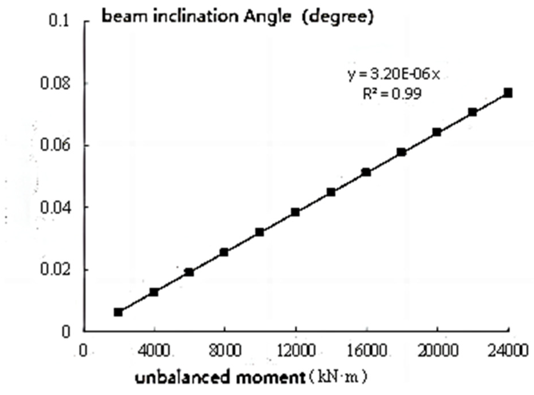
The precision of high-accuracy electronic inclinometers used in engineering inspections domestically can reach 0.001 degrees. Therefore, by using the previously obtained Ca girder inclination flexibility coefficient and substituting the measurement precision of the inclinometer into calculation Formula (11), the measurement precision of an unbalanced bending moment using such precision electronic inclinometers can be calculated as 315 kN·m.
(2)
Domestic displacement sensors (such as dial gauges) can achieve a measurement accuracy of 0.001 mm. Similarly, according to the calculation Formula (15) provided in this paper, the pier top horizontal displacement flexibility Ka = 3.39   ×   10 4 can be obtained. Thus, using this sensor (dial gauge) for measuring unbalanced bending moments yields a precision of 2.95 kN·m. Additionally, the horizontal displacement flexibility coefficient in the middle of the pier is represented as Kac = 7.83 × 10 5 . Therefore, the measurement precision of an unbalanced bending moment using this sensor (dial gauge) is 12.77 kN·m.
A comparison of the two monitoring methods indicates that, under conditions permitting the erection of fixed brackets at the construction site, the method of installing displacement sensors (dial gauges) at the top or middle of frame piers for monitoring achieves higher accuracy in measuring unbalanced bending moments. Although the method of installing electronic inclinometers on the top surface of beams does not achieve high precision in measuring unbalanced bending moments, it is convenient for instrument installation and does not require the erection of fixed brackets.
Considering that unbalanced bending moments only affect frame pier crossbeams when they exceed 1000 kN·m, it is preferable to use the convenient electronic inclinometer observation method for monitoring beam inclination in the construction monitoring of frame pier crossbeams on the Guang-Fo-Zhao Expressway.
During the construction monitoring of the frame pier crossbeams of the bridge, two high-precision electronic inclinometers are placed on the top surface of pier A to monitor the variation in the beam inclination Φ. Then, the counterweight is calculated using Formula (26), and its average value is taken as the applied counterweight. Starting from the fourth segment, after completing the concrete pouring of each segment, the inclination angle of the beam is monitored to determine the counterweight until closure. By observing the changes in the inclination of the frame pier crossbeams during construction, if significant unbalanced bending moments are detected, water tank counterweights are promptly applied to eliminate the effects of unbalanced loads.

5. Conclusions

This study investigates the monitoring technology for frame pier crossbeams during the cantilever construction of prestressed concrete box girders, and the conclusions are as follows:
  • By establishing a refined finite element model of the entire bridge using Midas/FEA, an analysis of potential unbalanced load combinations during symmetrical cantilever construction was conducted. The results indicate that the torsional resistance of frame pier crossbeams does not meet design specifications during construction.
  • By separating the frame pier from the box girder and employing structural mechanics methods to analyze the deformation of frame piers under torsional loads, this paper derived theoretical calculation formulas for the relationship between unbalanced bending moments and pier crossbeam inclination, as well as the relationship between unbalanced bending moments and horizontal displacement of variable section piers. These formulas provide convenient theoretical calculations for monitoring the torsion of frame pier crossbeams during construction.
  • Building upon the theoretical formulas for calculating frame pier crossbeam monitoring, two methods for monitoring the torsion of frame pier crossbeams during construction were proposed: a method combining water tank counterweight control with monitoring of pier crossbeam end inclination, and a method combining water tank counterweight control with monitoring of pier horizontal displacement.
  • In practical engineering construction monitoring, using a refined finite element bridge model to establish numerical fitting formulas for the relationship between unbalanced bending moments and pier crossbeam inclination yields results consistent with the theoretical formulas derived in this paper. This validates the correctness of the theoretical calculation formulas obtained in this study. Moreover, these theoretical formulas for frame pier crossbeam monitoring are convenient to use, require minimal computational effort, and hold significant value for widespread application.
  • Through practical engineering application and comparative analysis, it was found that the method combining water tank counterweight control with monitoring of pier horizontal displacement achieves higher accuracy in unbalanced bending moment monitoring. However, difficulties may arise in implementing fixed bracket installation for sensor placement. On the other hand, the method combining water tank counterweight control with monitoring of pier crossbeam end inclination is operationally convenient and provides sufficient accuracy for unbalanced bending moment monitoring to meet engineering requirements.
The method presented in this paper has been applied to the construction monitoring of the Chaoyang Bridge with good results, and it can provide valuable references for the construction monitoring of large-span frame pier continuous bridges.

Author Contributions

Conceptualization, H.F.; methodology, X.L.; software, F.L.; validation, X.Z.; investigation, S.L.; resources, N.M.; writing—original draft preparation, F.L.; writing—review and editing, L.G.; funding acquisition, L.G. All authors have read and agreed to the published version of the manuscript.

Funding

This research received no external funding.

Data Availability Statement

Data generated or analyzed during this study are provided in full within the published article.

Conflicts of Interest

Author Fanggang Liu and Haishan Fu was employed by the company Guangzhou Highway Co., Ltd., author Xiaolong Zhao was employed by the company Guangzhou Yuedong Country Garden Investment Co., Ltd. The remaining authors declare that the research was conducted in the absence of any commercial or financial relationships that could be construed as a potential conflict of interest.

References

  1. Zhang, H.; Li, Y.; Wang, X.; Chang, Z. Study on the mechanical properties of the prestressed concrete cover beam for the frame pier. Concrete 2023, 33, 146–148. (In Chinese) [Google Scholar]
  2. Song, Z.; Li, Z. Discussion on the space analysis and design and calculation method of large cantilever and wide box beam. Highw. Eng. 2022, 47, 9–12. (In Chinese) [Google Scholar]
  3. Li, F. Study on the design of long-span steel beam frame pier of high-speed railway high pier. China Railw. 2020, 10, 94–102. (In Chinese) [Google Scholar]
  4. Wang, J. Analysis of influence factors of railway steel beam frame pier design. Shanxi Archit. 2020, 36, 132–134. (In Chinese) [Google Scholar]
  5. Zhang, M. Application of large-span frame pier in the span bridge. Highway 2009, 99–101. (In Chinese) [Google Scholar]
  6. Du, Z.; Zhao, W.; Chen, J.; Liu, G. Local force analysis of the box beam. Highw. Eng. 2022, 45, 30–35. (In Chinese) [Google Scholar]
  7. Xu, Y.; Sun, T. Research on automatic monitoring technology of single-box three-room suspended cast girder bridge construction. Highway 2023, 142–148. (In Chinese) [Google Scholar]
  8. Jin, Y.; Zhu, Q.; Xu, W.; Wang, J.; Han, F. Construction control technology for multi-span corrugated steel web continuous beam bridge. Highway 2023, 163–165. (In Chinese) [Google Scholar]
  9. Liu, Y. Research on Construction Monitoring Technology of Yanshi Railway. Master’s Thesis, Beijing University of Technology, Beijing, China, 2023. (In Chinese). [Google Scholar]
  10. Beijing Midas Technology Co., Ltd. MIDAS/FEA User Manual Book 2-Analysis and Computing Tational Principles; Beijing Midas Technology Co., Ltd.: Beijing, China, 2013. (In Chinese) [Google Scholar]
  11. Yang, F.; Li, J. Structural Mechanics; Higher Education Press: Beijing, China, 1998. (In Chinese) [Google Scholar]
  12. Hong, Y. Experimental Study of Reinforced Concrete Beams Strengthened with CFRP. In Proceedings of the 8th International Conference on Civil Engineering. ICCE 2021, Nanchang, China, 4–5 December 2021; Feng, G., Ed.; Lecture Notes in Civil Engineering; Springer: Singapore, 2022; Volume 213. [Google Scholar] [CrossRef]
  13. Fan, K. Comparative Analysis of the Displacement Dynamic Load Allowance and Bending Moment Dynamic Load Allowance of Highway Continuous Girder Bridge. In Proceedings of the 8th International Conference on Civil Engineering. ICCE 2021, Nanchang, China, 4–5 December 2021; Feng, G., Ed.; Lecture Notes in Civil Engineering; Springer: Singapore, 2022; Volume 213. [Google Scholar] [CrossRef]
  14. Jiang, Z.; Zhang, Y.; Liu, H.; Li, X. Symplectic Elastic Solution of Multi-layer Thick-Walled Cylinder Under Different Interlayer Constraints. In Proceedings of the 8th International Conference on Civil Engineering. ICCE 2021, Nanchang, China, 4–5 December 2021; Feng, G., Ed.; Lecture Notes in Civil Engineering; Springer: Singapore, 2022; Volume 213. [Google Scholar] [CrossRef]
  15. Xiao, Y.; Fu, K.; Li, Z.; Zeng, Z.; Bai, J.; Huang, Z.; Huang, X.; Yuan, Y. Research on Construction Process of Steel Beam Incremental Launching Based on Finite Element Method. In Proceedings of the 8th International Conference on Civil Engineering. ICCE 2021, Nanchang, China, 4–5 December 2021; Feng, G., Ed.; Lecture Notes in Civil Engineering; Springer: Singapore, 2022; Volume 213. [Google Scholar] [CrossRef]
  16. Jiang, Y.; Long, P. Parameter Sensitivity Analysis of Long Span PC Continuous Beam Bridge with Corrugated Steel Webs. In Proceedings of the 8th International Conference on Civil Engineering. ICCE 2021, Nanchang, China, 4–5 December 2021; Feng, G., Ed.; Lecture Notes in Civil Engineering; Springer: Singapore, 2022; Volume 213. [Google Scholar] [CrossRef]
  17. The finite element software Midas/FEA.
  18. Belwal, A.; Thapliyal, S.; Jhinkwan, V.S. Construction Stage Analysis of Continuous Box Girder Bridge Constructed via Full Staging and Balance Cantilever Method. In Recent Advances in Structural Engineering and Construction Management; Lecture Notes in Civil Engineering; Springer: Berlin/Heidelberg, Germany, 2023; Volume 277, pp. 89–99. Available online: https://www.engineeringvillage.com/app/doc/?docid=cpx_M4cb62b1842f969ae4M65f21017816355 (accessed on 10 June 2024). [CrossRef]
  19. Farré-Checa, J.; Komarizadehasl, S.; Ma, H.; Lozano-Galant, J.A.; Turmo, J. Direct simulation of the tensioning process of cable-stayed bridge cantilever construction. Autom. Constr. 2022, 137, 104197. Available online: https://www.engineeringvillage.com/app/doc/?docid=cpx_2e3e64ee187d8e1af9bM71a010178165143&pageSize=25&index=1&searchId=4bd5dcf1fed44e568a22ac3fd7bc40bd&resultsCount=24&usageZone=resultslist&usageOrigin=searchresults&searchType=Quick (accessed on 10 June 2024). [CrossRef]
  20. Rashed, M.; Mehanny, S.S.F. Simulating creep induced moment redistribution in prestressed concrete bridges constructed by the balanced cantilever method: Ad hoc traditional formulae versus real time-dependent analysis. J. Eng. Appl. Sci. 2023, 70, 28. Available online: https://www.engineeringvillage.com/app/doc/?docid=cpx_2e3e64ee187d8e1af9bM71a010178165143&pageSize=25&index=2&searchId=5f271ece67bc4190a5cb20df770c204d&resultsCount=26933&usageZone=resultslist&usageOrigin=searchresults&searchType=Quick (accessed on 10 June 2024). [CrossRef]
  21. Dias Filho, J.L.E.; de Almeida Maia, P.C. A Non-conventional Durability Test for Simulating Creep of Geosynthetics Under Accelerated Degradation. Int. J. Geosynth. Ground Eng. 2021, 7. Available online: https://www.engineeringvillage.com/app/doc/?docid=cpx_Ma74c417bdf9d9ca5M6ebf1017816328&pageSize=25&index=3&searchId=4bd5dcf1fed44e568a22ac3fd7bc40bd&resultsCount=24&usageZone=resultslist&usageOrigin=searchresults&searchType=Quick (accessed on 10 June 2024). [CrossRef]
  22. Musarat, M.A.; Khan, A.M.; Alaloul, W.S.; Blas, N.; Ayub, S. Automated monitoring innovations for efficient and safe construction practices. Results Eng. 2024, 22, 102057. Available online: https://www.engineeringvillage.com/app/doc/?docid=cpx_6179457f18ee12b5cb4M635a1017816523&pageSize=25&index=4&searchId=800c9673907c4cc695c858c4f987be74&resultsCount=116857&usageZone=resultslist&usageOrigin=searchresults&searchType=Quick (accessed on 10 June 2024). [CrossRef]
  23. Gong, B.; Feng, L.; Liu, J.; Liu, S.; Wang, Z.; Liu, Y. Finite-Element Analysis of Temperature Field and Effect on Steel-Concrete Composite Pylon of Cable-Stayed Bridge without Backstays. Buildings 2024, 14, 1731. [Google Scholar] [CrossRef]
  24. Liu, F.; Gu, L.; Fu, H.; Li, X.; Zhao, X.; Ma, N.; Guo, Z. Research on the Method of Prestressing Tendon Layout for Large-Span Prestressed Components Continuous Rigid Frame Bridge Based on “Zero Bending Moment Dead Load Theory”. Buildings 2024, 14, 1588. [Google Scholar] [CrossRef]
  25. Zhou, H.; Qi, X.; Liu, Z.; Xue, W.; Sun, J.; Liu, J.; Gui, S.; Yang, X. Asymmetric Cantilever Construction Control of a U-Shaped Box Concrete Continuous Bridge in Complex Environment. Buildings 2023, 13, 591. [Google Scholar] [CrossRef]
  26. Xu, F.; Cheng, Y.; Wang, K.; Zhou, M. Transverse Analysis of Box Girders with Corrugated Steel Webs. Buildings 2024, 14, 574. [Google Scholar] [CrossRef]
  27. He, X.; Wang, Z.; Li, C.; Gao, C.; Liu, Y.; Li, C.; Liu, B. Experimental Test and Finite Element Analysis on a Concrete Box Girder of a Cable-Stayed Bridge with W-Shaped Prestressed Concrete Diagonal Braces. Buildings 2024, 14, 506. [Google Scholar] [CrossRef]
  28. Chen, Y.; Zhang, Y.; Yu, M.; Hu, X.; He, W.; Qin, K.; Zhu, Y.; Wei, X. Structural Design and Mechanical Behavior Investigation of Steel–Concrete Composite Decks of Narrow-Width Steel Box Composite Bridge. Buildings 2024, 14, 912. [Google Scholar] [CrossRef]
  29. Peng, W.; Lu, W.; Liu, S.; Liu, Y.; Xu, L.; Li, F. Experimental and Numerical Study on the Seismic Performances of Reinforcement-Embedded RC Column-to-Precast Cap Beams with Socket Connections. Buildings 2023, 13, 2367. [Google Scholar] [CrossRef]
Figure 1. The layout of bridge (cm).
Buildings 14 02409 g001
Figure 2. Refined finite element model.
Buildings 14 02409 g002
Figure 3. Grid division of key sections of the main girder. (a) Section of pier top. (b) Midspan section.
Buildings 14 02409 g003
Figure 4. Main tensile stress cloud map of frame pier crossbeam. (a) Axonometric drawing(N, mm). (b) Left side plot(N, mm). (c) right hand view(N, mm).
Buildings 14 02409 g004aBuildings 14 02409 g004b
Figure 5. Simplified diagram of frame pier calculation.
Buildings 14 02409 g005
Figure 6. The Basic System of Frame Pier Calculation.
Buildings 14 02409 g006
Figure 7. Calculation diagram of variable section pier.
Buildings 14 02409 g007
Figure 8. Deformation cloud map of frame pier crossbeam.
Buildings 14 02409 g008
Figure 9. Fitting diagram of beam inclination angle and unbalanced bending moment.
Buildings 14 02409 g009
Table 1. Details of the model.
Details of the Model
Model compositionSolid elements
Meshing methodUsing automatically generated tetrahedral solid meshes with smooth variation in size.
Grids size0.5 m
Types of loadsUnbalanced loads
Specific methods of applying loadsThe specific method of applying loads involves applying a surface pressure of 0.49 kPa on one side to support materials for cantilever stacking tools. Deviations in the basket and template are addressed by applying a concentrated force of 840 kN on one side of the cantilever end and 560 kN on the other side. For the final cantilever block, asynchronous construction is achieved by only modeling half of the segment on one side for calculation purposes. Asymmetric vertical wind loads are addressed by applying a surface pressure of 0.23 kPa on one side.
Table 2. Division of construction stages.
NumberDaysDescription of Construction Content
145Main pier and foundation
230Pour 0# segments
31Pull T1 and F1
420Hang the basket assembly, pre-press
58Pouring section 1#
61Pull T2 and F2
71Hang the basket forward
8~3079Past and tension the 2#–9# section
318Side across the pouring
3210The edge across the close
332Tension side across the steel beam
340Remove the side span bracket and make temporary consolidation
3510In the cross close
362Tension in the span steel beam
378Remove the whole bridge hanging basket
3810The second phase of paving
393650Operating for ten years
Table 3. The inclination angle of the crossbeam corresponding to the unbalanced bending moment.
Unbalanced Moment
(kN·m)
Cross am Inclination (degree)Unbalanced Moment
(kN·m)
Cross am Inclination (degree)
20000.006414,0000.0448
40000.012816,0000.0513
60000.019218,0000.0577
80000.025620,0000.0641
10,0000.032022,0000.0705
12,0000.038424,0000.0769
Disclaimer/Publisher’s Note: The statements, opinions and data contained in all publications are solely those of the individual author(s) and contributor(s) and not of MDPI and/or the editor(s). MDPI and/or the editor(s) disclaim responsibility for any injury to people or property resulting from any ideas, methods, instructions or products referred to in the content.

