

Assessment of the Compound Damping of a System with Parallelly Coupled Anti-Seismic Devices


Abstract
:1. Introduction
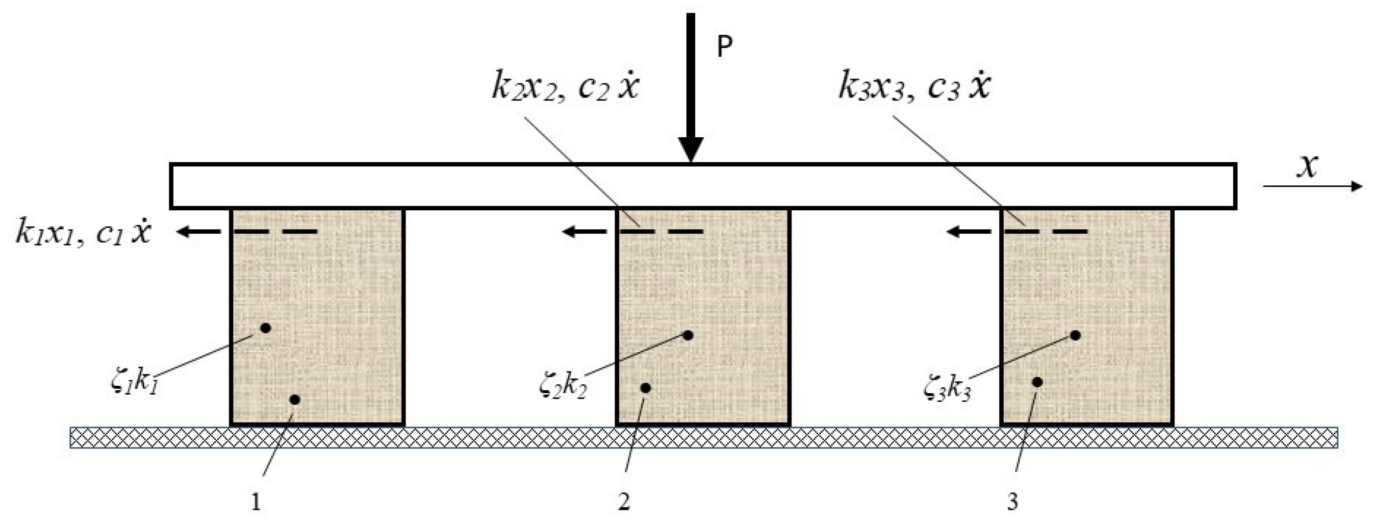
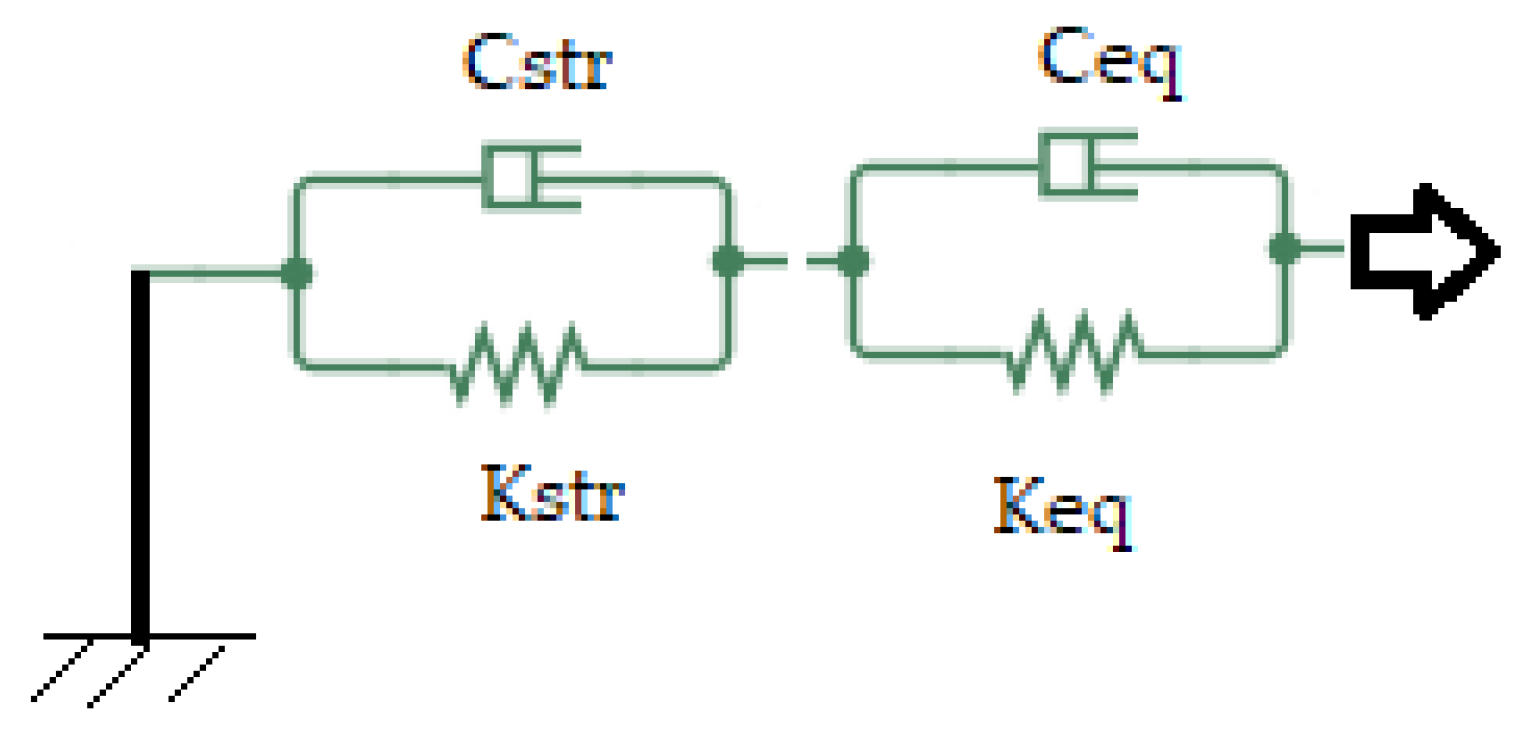
2. Analytical Assessment of Compound Modal Amortization/Damping
- (a)
- The energy dissipated on mode r, for a complete cycle, corresponding to device i, is
- (b)
- The maximum elastic energy (of deformation) on r mode, for device i, can be written down as
3. Results
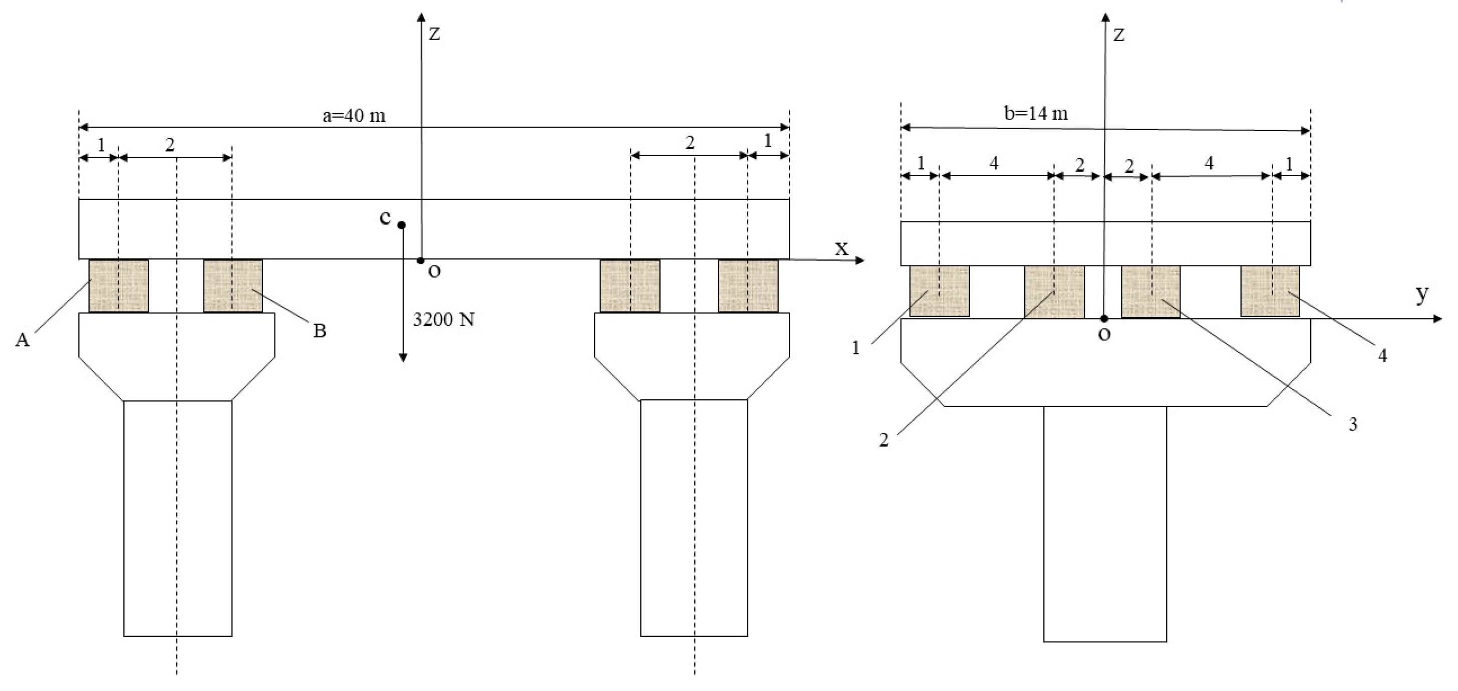
3.1. Case Study
3.2. Specific Results
4. Conclusions
- (a)
- For a structural system containing several anti-seismic or anti-vibratile devices distinct from one another, with elastic characteristics and damping ratios , where i is the order index, i = 1…n, based on Relation (6), the (effective) equivalent amortization/damping rate can be determined for each r vibration mode;
- (b)
- If the structural system has a dominant displacement in the instantaneous alternative translation in a certain direction and elastic devices and/or the devices are different, with parameters ki,, as a result of the parallel connection, then the calculation for at a fundamental mode with can be performed using Relations (9) or (10);
- (c)
- This case study shows that natural modal amortizations , i = 1…4, are significantly influenced by the stiffness ratios as with j = 2…4;
- (d)
- can be obtained from permutations in the − relationship for a specific situation;
- (e)
- For large constructions, the use of only one type of seismic isolation device is not the optimal economical solution, and using more than one type could be more acceptable with a certain combination of technical characteristics;
- (f)
- Some estimative values for the equivalent circular frequency are determined considering the existing correlations between the defining quantities (mass, stiffness, and damping), and are of interest, especially in the case of eccentricities between the center of mass and center of rigidity;
- (g)
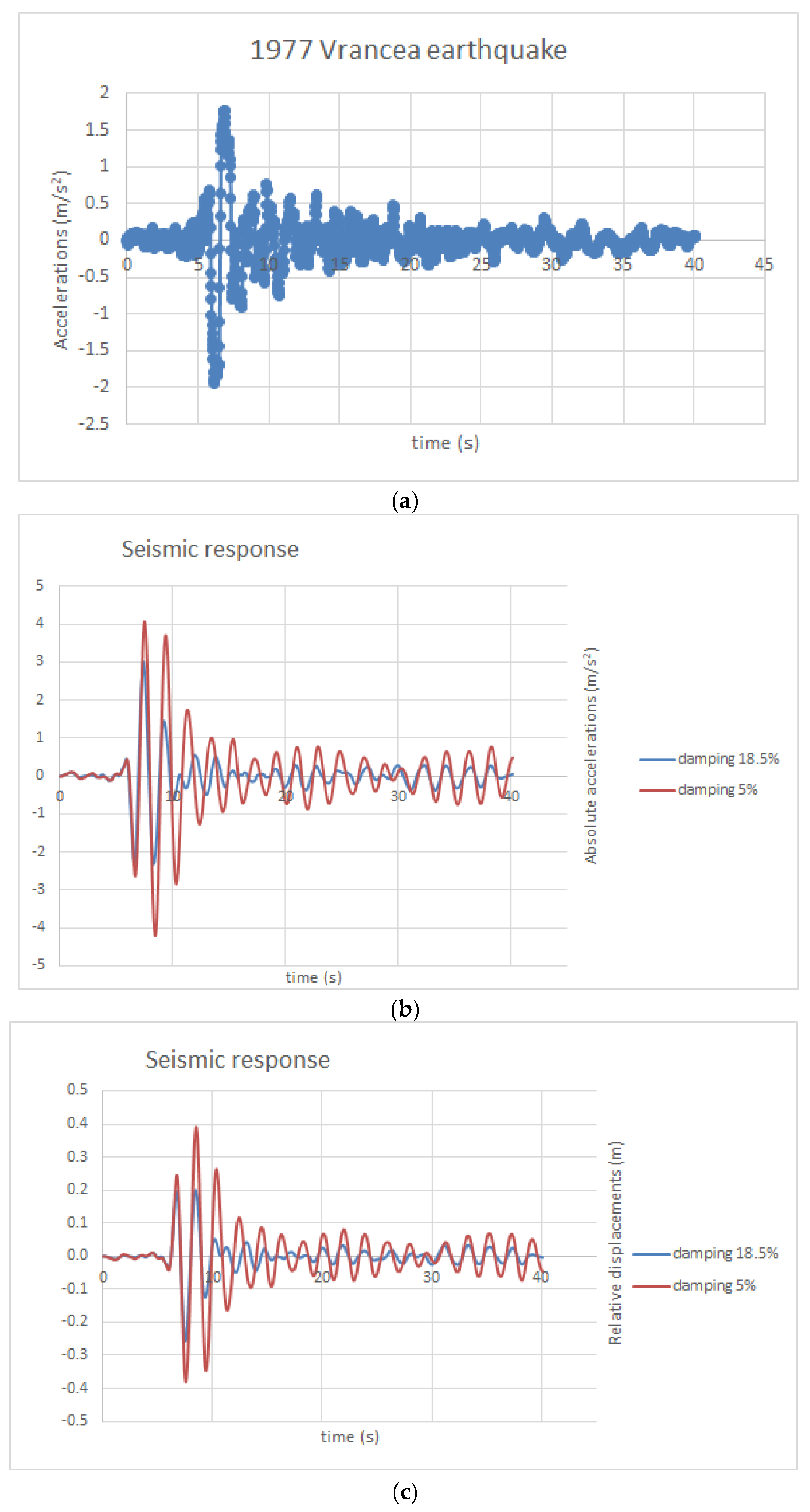
- We determined the seismic response considering the Vrancea 1977 accelerogram for the critical damping ratios of 5% and 18.5%, and the results highlight a different dynamic behavior of the system with its natural vibration frequency of 0.52 Hz, in terms of absolute accelerations and relative displacements;
- (h)
- The maximum value of the elastic horizontal displacement d = 0.25 m is smaller than , but larger than the maximum displacement equal to 0.20 m, considering a 0.185 value for damping;
- (i)
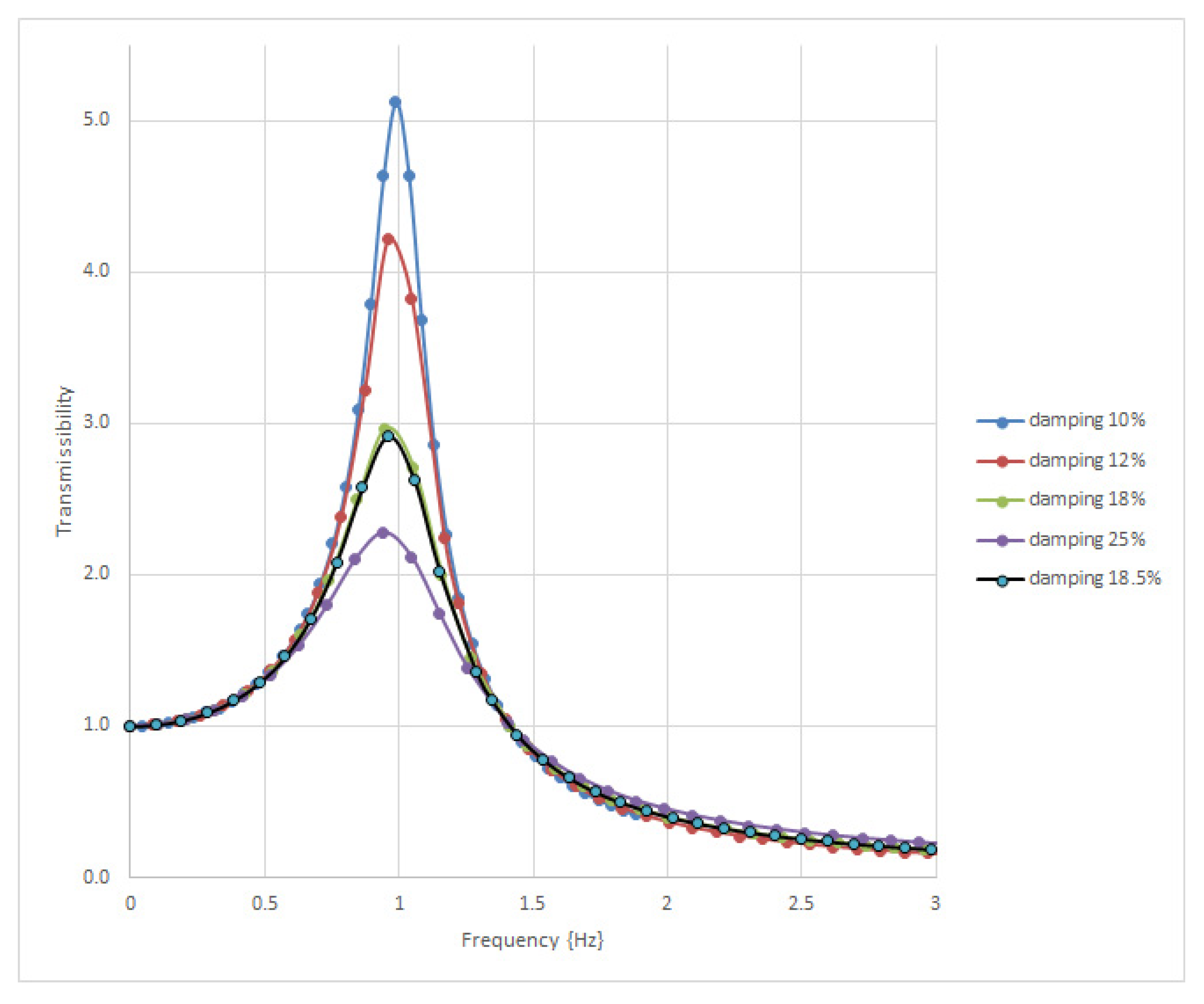
- The performance of an isolation system was determined by the transmissibility factor of the system so that the variation in the factor was found to be in correlation with the determined equivalent amortization.
Author Contributions
Funding
Data Availability Statement
Conflicts of Interest
References
- Pavel, F.; Vacareanu, R.; Radulian, M.; Cioflan, C. Investigation on directional effects of Vrancea subcrustal earthquakes. Earthq. Eng. Eng. Vib. 2015, 14, 399–410. [Google Scholar] [CrossRef]
- Pavel, F. An updated perspective of the impact of the 1940 Vrancea earthquake on design and construction practices in Romania. Buildings 2024, 14, 1152. [Google Scholar] [CrossRef]
- Fujino, Y.; Siringoringo, D.; Kikuchi, M.; Kasai, K.; Kashima, T. Seismic Monitoring of Seismically Isolated Bridges and Buildings in Japan—Case Studies and Lessons Learned. In Genetic Enhancement of Crops for Tolerance to a Biotic Stress: Mechanisms and Approaches; Springer Tracts in Civil Engineering; Springer: Cham, Switzerland, 2019; Volume 1, pp. 407–447. [Google Scholar] [CrossRef]
- Montes, K.; Dang, J. Seismic isolated bridge performance evaluation and design proposal using artificial neural network. Earthq. Eng. Resil. 2023, 2, 364–378. [Google Scholar] [CrossRef]
- Makris, N.; Chang, S.P. Effect of Damping Mechanisms on the Response of Seismically Isolated Structures; Pacific Earthquake Engineering Research Center: Berkeley, CA, USA, 1998. [Google Scholar]
- Makris, N.; Zhang, J. Structural Characterization and Seismic Response Analysis of a Highway Overcrossing Equipped with Elastomeric Bearings and Fluid Dampers: A Case Study; Pacific Earthquake Engineering Research Center: Berkeley, CA, USA, 2002. [Google Scholar]
- Simionescu, C.S.; Leopa, A. The seismic response evaluation of a bridge deck, isolated by rubber bearings. Acta Tech. Napoc. Ser. Appl. Math. Mech. Eng. 2020, 63, 51–60. [Google Scholar]
- Pastia, C.; Luca, S.G. Seismic Protection of a Realistic Bridge Structure Using Passive Friction Devices. Bull. Polytech. Inst. Jassy Constr. Archit. Sect. 2012, 58, 77–84. [Google Scholar]
- Paulet-Crainiceanu, F.; Florea, V.; Luca, S.G.; Pastia, C.; Rosca, O.V. Analysis of practical application aspects for an active control strategy to civil engineering structures. In Perspectives in Dynamical Systems II—Numerical and Analytical Approaches; Awrejcewicz, J., Ed.; Springer Proceedings in Mathematics & Statistics; Springer: Cham, Switzerland, 2024; Volume 454. [Google Scholar] [CrossRef]
- Zhou, X.Y.; Han, M.; Yang, L. Study on protection measures for seismic isolation rubber bearings. ISET J. Earthq. Technol. 2003, 40, 137–160. [Google Scholar]
- Tonciu, O.; Bratu, P. Evaluation of the energetic parameters of viscous dissipation for dynamic systems excited in harmonic regime. Acta Tech. Napoc.-Ser. Appl. Math. Mech. Eng. 2023, 66, 367–374. [Google Scholar]
- Lee, S.; Feng, M.Q.; Kwon, S.J.; Hong, S.H. Equivalent Modal Damping of Short-Span Bridges Subjected to Strong Motion. J. Bridge Eng. 2011, 16, 316–323. [Google Scholar] [CrossRef]
- Bratu, P. Dynamic Rigidity of The Linear Voigt—Kelvin Viscoelastic Systems. Rom. J. Acoust. Vib. 2019, 16, 184–188. [Google Scholar]
- Bratu, P. Modal Amortization Rate Equivalent to a Structural System with Elastomer Insulators. Rom. J. Acoust. Vib. 2020, 17, 27–31. [Google Scholar]
- Potirniche, A. Assessments regarding effective configurations of vibration isolators based on displacements analysis. Rom. J. Acoust. Vib. 2015, 12, 126–131. [Google Scholar]
- Sireteanu, T. Smart suspension systems. Rom. J. Acoust. Vib. 2016, 13, 2. [Google Scholar]
- SR EN 15129; Anti-Seismic Devices. National Organization for Standardization—ASRO: Bucharest, Romania, 2018.
- SR EN 1337; Support Devices for Structures. Part 3: Elastomer Bearing Devices. National Organization for Standardization—ASRO: Bucharest, Romania, 2005.
- Technical Solutions for Isolating the Viaducts for the “Transilvania” Highway in Romania; Evaluation and Test Report; ICECON: Bucharest, Romania, 2021.
- Chopra, A.K. Dynamics of Structures: Theory and Applications to Earthquake Engineering; Prentice Hall: Upper Saddle River, NJ, USA, 2012. [Google Scholar]
- Tsai, H.C.; Kelly, J.M. Seismic response of heavily damped base isolation systems. Earthq. Eng. Struct. Dyn. 1993, 22, 633–645. [Google Scholar] [CrossRef]
- Kelly, J.M.; Tsai, H.C. Seismic response of light internal equipment in base-isolated structures. Earthq. Eng. Struct. Dyn. 1985, 13, 711–712. [Google Scholar] [CrossRef]
- Anajafi, H.; Medina, R.A.; Santini-Bell, E. Effects of the improper modeling of viscous amortization on the first-mode and higher-mode dominated responses of base-isolated buildings. Earthq. Eng. Struct. Dyn. 2020, 49, 51–73. [Google Scholar] [CrossRef]
- Scutaru, M.L.; Vlase, S.; Marin, M.; Modrea, A. New analytical method based on dynamic response of planar mechanical elastic systems. Bound. Value Probl. 2020, 2020, 104. [Google Scholar] [CrossRef]
- Hu, X.; Chen, Q.; Weng, D.; Zhang, R.; Ren, X. Estimation of Additional Equivalent Amortization Ratio of the Damped Structure Based on Energy Dissipation. Adv. Civ. Eng. 2019, 2019, 8052413. [Google Scholar] [CrossRef]
- Suarez, L.E.; Gaviria, C.A. Equivalent frequencies and amortization ratios of buildings with viscous fluid dampers: A closed form formulation. In Proceedings of the 10 NCEE-Frontiers of Earthquake Engineering, Anchorage, AK, USA, 21–25 July 2014. [Google Scholar]
- Bratu, P. Compound Amortization for Coupled Dynamic Systems. Acta Tech. Napoc. Ser. Appl. Math. Mech. Eng. 2020, 63, 239–242. [Google Scholar]
- Bratu, P.; Mitu, A.M.; Vasile, O. Dissipation Capacity Evaluation for Neoprene Anti-Seismic Isolators Under Harmonic Dynamic Excitations. Rom. J. Acoust. Vib. 2011, 8, 67–71. [Google Scholar]
- Murzea, P. Alternative Kinematic Assumptions for the Motions of Structures with Multiple Dynamic Degrees of Freedom Subjected to Seismic Actions. Rom. J. Acoust. Vib. 2014, 11, 53–58. [Google Scholar]
- Radeș, M. Resonance Methods for the Dynamic Analysis of deformable structures. St. Cerc. Mec. Apl. 1993, 32, 607–633. [Google Scholar]
- Meirovitch, L. Principles and Techniques of Vibrations, 1st ed.; Prentice Hall International Editions Series; Pearson: Piscataway, NJ, USA, 1996. [Google Scholar]
- Integrative Concept of Digital Analysis of Data from Large-Scale Seismic Monitoring of the National Territory and the Built Environment, Intended for the Rapid Identification of the Destructive Potential Of Seismic Events Produced in Romania and in the Adjacent Regions Nucleus Programme PN23350101. Available online: https://incd.ro/proiecte-nationale/ (accessed on 30 July 2024).

| i-Type Elastomeric Device | [MPa] | [105 N/m] | [104 Ns/m] | [%] |
|---|---|---|---|---|
| 1 | 0.15 | 1 | 0.3 | 10 |
| 2 | 0.25 | 1.5 | 1 | 12 |
| 3 | 0.40 | 2.5 | 3 | 18 |
| 4 | 0.55 | 3 | 5 | 25 |
| 1 | 2.5 | 3 | 1.5 | 0.25 | 0.12 | 0.1 | 0.18 | 0.14 |
| 1 | 3 | 2.5 | 1.5 | 0.25 | 0.12 | 0.1 | 0.18 | 0.141 |
| 1 | 3 | 2.5 | 1.5 | 0.18 | 0.12 | 0.1 | 0.25 | 0.145 |
| 1 | 1.5 | 2.5 | 3 | 0.25 | 0.12 | 0.18 | 0.1 | 0.147 |
| 1 | 2.5 | 3 | 1.5 | 0.25 | 0.18 | 0.12 | 0.1 | 0.151 |
| 1 | 1.5 | 3 | 2.5 | 0.25 | 0.12 | 0.18 | 0.1 | 0.152 |
| 1 | 2.5 | 3 | 1.5 | 0.25 | 0.12 | 0.18 | 0.1 | 0.155 |
| 1 | 1.5 | 2.5 | 3 | 0.12 | 0.25 | 0.18 | 0.1 | 0.155 |
| 1 | 2.5 | 1.5 | 3 | 0.1 | 0.18 | 0.25 | 0.12 | 0.160 |
| 1 | 1.5 | 3 | 2.5 | 0.18 | 0.1 | 0.12 | 0.25 | 0.164 |
| 1 | 2.5 | 3 | 1.5 | 0.1 | 0.25 | 0.12 | 0.18 | 0.169 |
| 1 | 3 | 1.5 | 2.5 | 0.18 | 0.25 | 0.12 | 0.1 | 0.17 |
| 1 | 2.5 | 3 | 1.5 | 0.12 | 0.1 | 0.25 | 0.18 | 0.173 |
| 1 | 2.5 | 3 | 1.5 | 0.1 | 0.12 | 0.25 | 0.18 | 0.177 |
| 1 | 2.5 | 3 | 1.5 | 0.12 | 0.25 | 0.18 | 0.1 | 0.179 |
| 1 | 3 | 2.5 | 1.5 | 0.1 | 0.18 | 0.25 | 0.12 | 0.180 |
| 1 | 2.5 | 3 | 1.5 | 0.12 | 0.18 | 0.25 | 0.1 | 0.183 |
| 1 | 1.5 | 3 | 2.5 | 0.1 | 0.12 | 0.25 | 0.18 | 0.185 |
| ωeq | ||||
|---|---|---|---|---|
| [rad/s] | 3.27 | 3.67 | 3.57 | 3.18 |
| estimated value/ exact value | 1 | 1.12 | 1.09 | 0.97 |
| fvibr [Hz] | Tω1, ζ1 | Tω2, ζ2 | Tω3, ζ3 | Tω4, ζ4 | Tωsystem, ζeq |
|---|---|---|---|---|---|
| 0 | 1 | 1 | 1 | 1 | 1 |
| 0.05 | 1.002 | 1.007 | 1.011 | 1.011 | 1.009 |
| 0.1 | 1.008 | 1.031 | 1.046 | 1.045 | 1.038 |
| 0.15 | 1.020 | 1.073 | 1.109 | 1.106 | 1.089 |
| 0.2 | 1.036 | 1.137 | 1.209 | 1.200 | 1.168 |
| 0.25 | 1.058 | 1.231 | 1.363 | 1.339 | 1.286 |
| 0.3 | 1.086 | 1.368 | 1.598 | 1.537 | 1.458 |
| 0.35 | 1.121 | 1.569 | 1.962 | 1.804 | 1.712 |
| 0.4 | 1.164 | 1.880 | 2.494 | 2.108 | 2.086 |
| 0.45 | 1.216 | 2.383 | 2.969 | 2.282 | 2.576 |
| 0.5 | 1.281 | 3.219 | 2.704 | 2.120 | 2.917 |
| 0.55 | 1.360 | 4.216 | 2.001 | 1.742 | 2.631 |
| 0.6 | 1.458 | 3.829 | 1.458 | 1.382 | 2.017 |
| 0.67 | 1.639 | 2.246 | 1.003 | 1.021 | 1.364 |
| 0.7 | 1.737 | 1.817 | 0.876 | 0.909 | 1.175 |
| 0.75 | 1.940 | 1.344 | 0.716 | 0.763 | 0.943 |
| 0.8 | 2.209 | 1.047 | 0.602 | 0.654 | 0.778 |
| 0.85 | 2.577 | 0.847 | 0.516 | 0.570 | 0.658 |
| 0.9 | 3.088 | 0.705 | 0.450 | 0.504 | 0.567 |
| 0.95 | 3.794 | 0.599 | 0.398 | 0.451 | 0.497 |
| 1 | 4.636 | 0.519 | 0.355 | 0.408 | 0.440 |
| 1.05 | 5.122 | 0.455 | 0.321 | 0.372 | 0.394 |
| 1.1 | 4.642 | 0.404 | 0.292 | 0.342 | 0.357 |
| 1.15 | 3.685 | 0.361 | 0.267 | 0.316 | 0.325 |
| 1.2 | 2.862 | 0.326 | 0.246 | 0.293 | 0.298 |
| 1.25 | 2.269 | 0.297 | 0.228 | 0.274 | 0.275 |
| 1.3 | 1.850 | 0.272 | 0.213 | 0.257 | 0.255 |
| 1.35 | 1.545 | 0.250 | 0.199 | 0.242 | 0.238 |
| 1.4 | 1.317 | 0.231 | 0.187 | 0.229 | 0.223 |
| 1.45 | 1.141 | 0.215 | 0.176 | 0.217 | 0.209 |
| 1.5 | 1.003 | 0.200 | 0.166 | 0.206 | 0.197 |
| 1.55 | 0.891 | 0.187 | 0.158 | 0.197 | 0.187 |
| 1.6 | 0.799 | 0.176 | 0.150 | 0.188 | 0.177 |
| 1.65 | 0.722 | 0.165 | 0.143 | 0.180 | 0.168 |
| 1.7 | 0.657 | 0.156 | 0.136 | 0.172 | 0.160 |
| 1.75 | 0.602 | 0.148 | 0.131 | 0.166 | 0.153 |
| 1.8 | 0.554 | 0.140 | 0.125 | 0.159 | 0.147 |
| 1.85 | 0.512 | 0.133 | 0.120 | 0.154 | 0.141 |
| 1.9 | 0.475 | 0.127 | 0.116 | 0.148 | 0.135 |
| 1.95 | 0.443 | 0.121 | 0.111 | 0.143 | 0.130 |
| 2 | 0.414 | 0.116 | 0.107 | 0.139 | 0.125 |
Disclaimer/Publisher’s Note: The statements, opinions and data contained in all publications are solely those of the individual author(s) and contributor(s) and not of MDPI and/or the editor(s). MDPI and/or the editor(s) disclaim responsibility for any injury to people or property resulting from any ideas, methods, instructions or products referred to in the content. |
© 2024 by the authors. Licensee MDPI, Basel, Switzerland. This article is an open access article distributed under the terms and conditions of the Creative Commons Attribution (CC BY) license (https://creativecommons.org/licenses/by/4.0/).
Share and Cite
Bratu, P.; Dragomir, C.-S.; Dobre, D. Assessment of the Compound Damping of a System with Parallelly Coupled Anti-Seismic Devices. Buildings 2024, 14, 2422. https://doi.org/10.3390/buildings14082422
Bratu P, Dragomir C-S, Dobre D. Assessment of the Compound Damping of a System with Parallelly Coupled Anti-Seismic Devices. Buildings. 2024; 14(8):2422. https://doi.org/10.3390/buildings14082422
Chicago/Turabian StyleBratu, Polidor, Claudiu-Sorin Dragomir, and Daniela Dobre. 2024. "Assessment of the Compound Damping of a System with Parallelly Coupled Anti-Seismic Devices" Buildings 14, no. 8: 2422. https://doi.org/10.3390/buildings14082422