
Glass-Aluminium Partition Walls with High-Damping Rubber Devices: Seismic Design and Numerical Analyses


Abstract
:1. Introduction
2. Development of the Design Concept
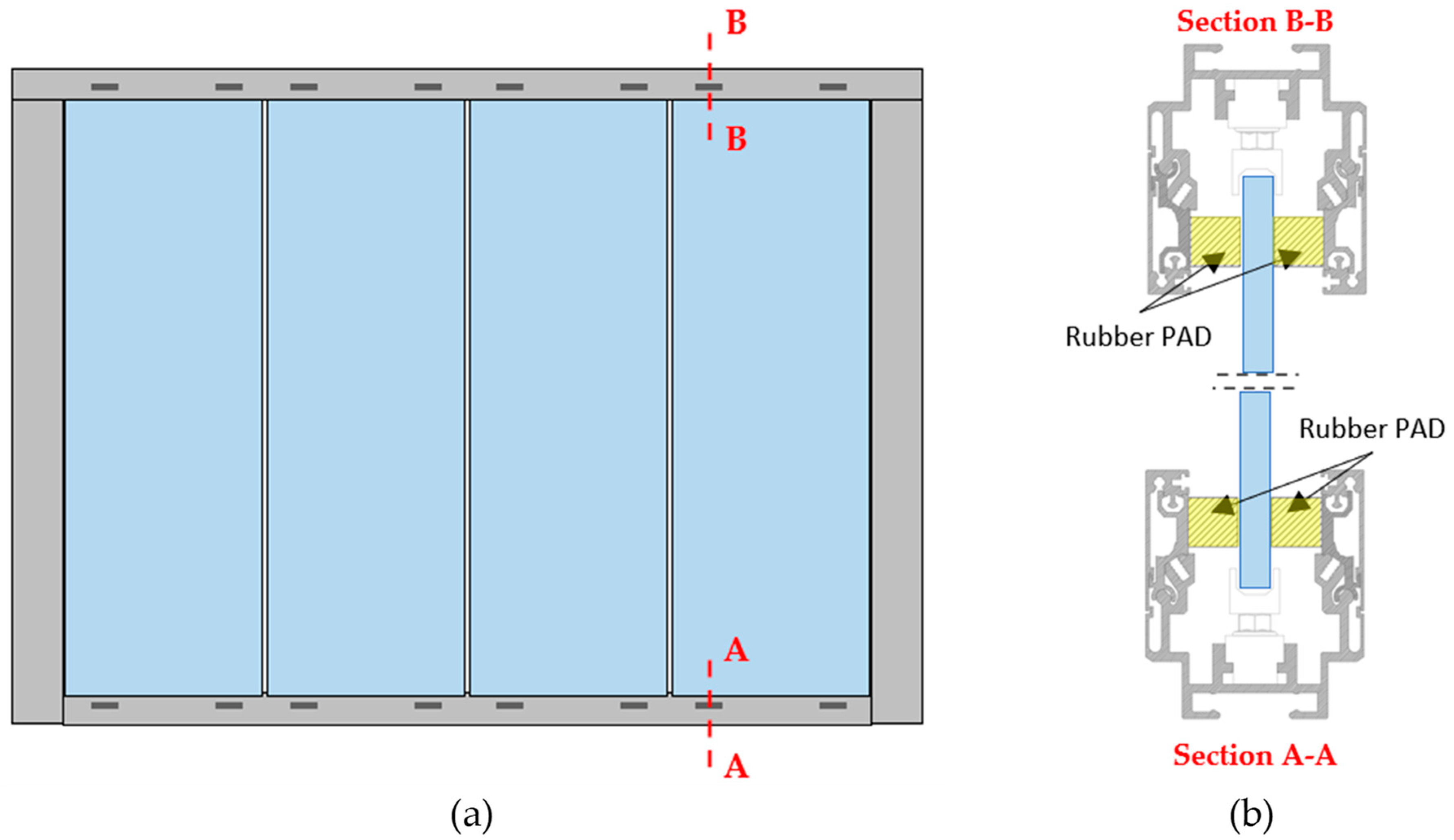
2.1. Partition Wall Concept “A”
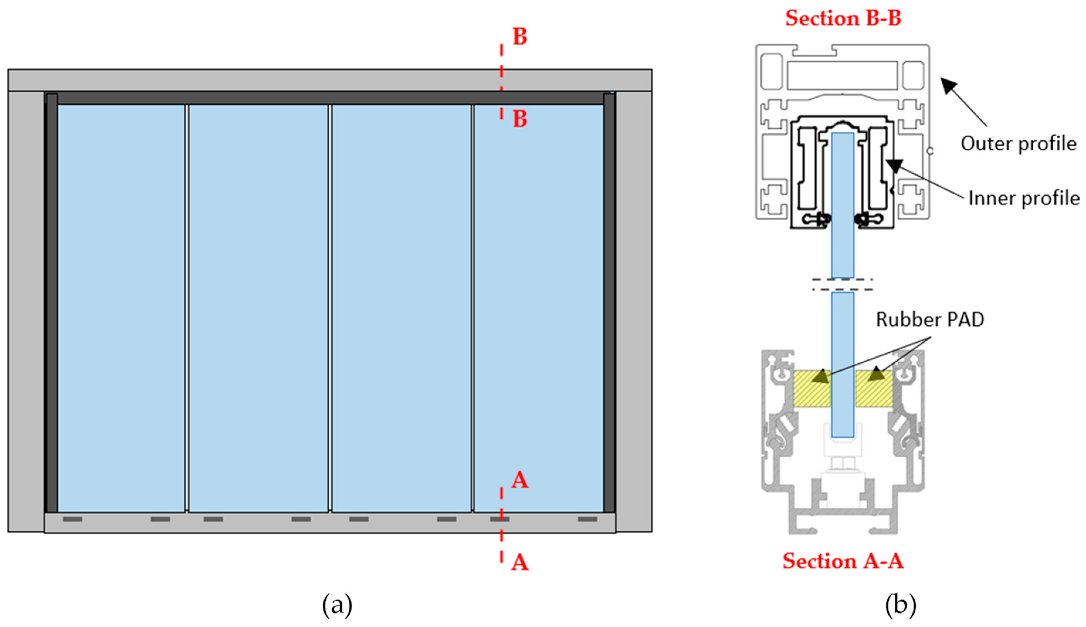
2.2. Partition Wall Concept “B”
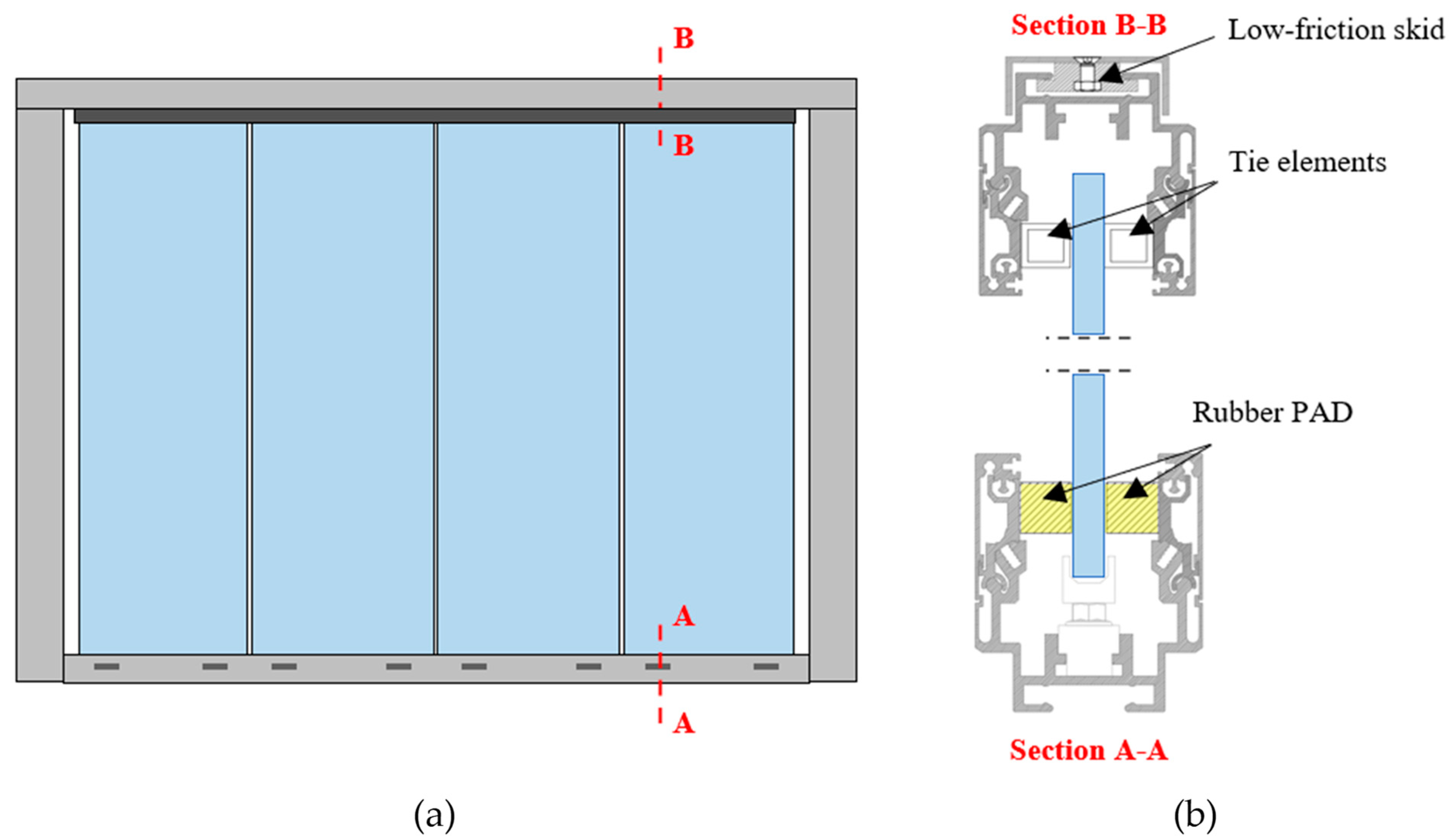
2.3. Partition Wall Concept “C” (Final)
3. Seismic Design and Detailing
3.1. Analysis of the Dissipative Mechanisms
3.2. Detailing of Partition Components
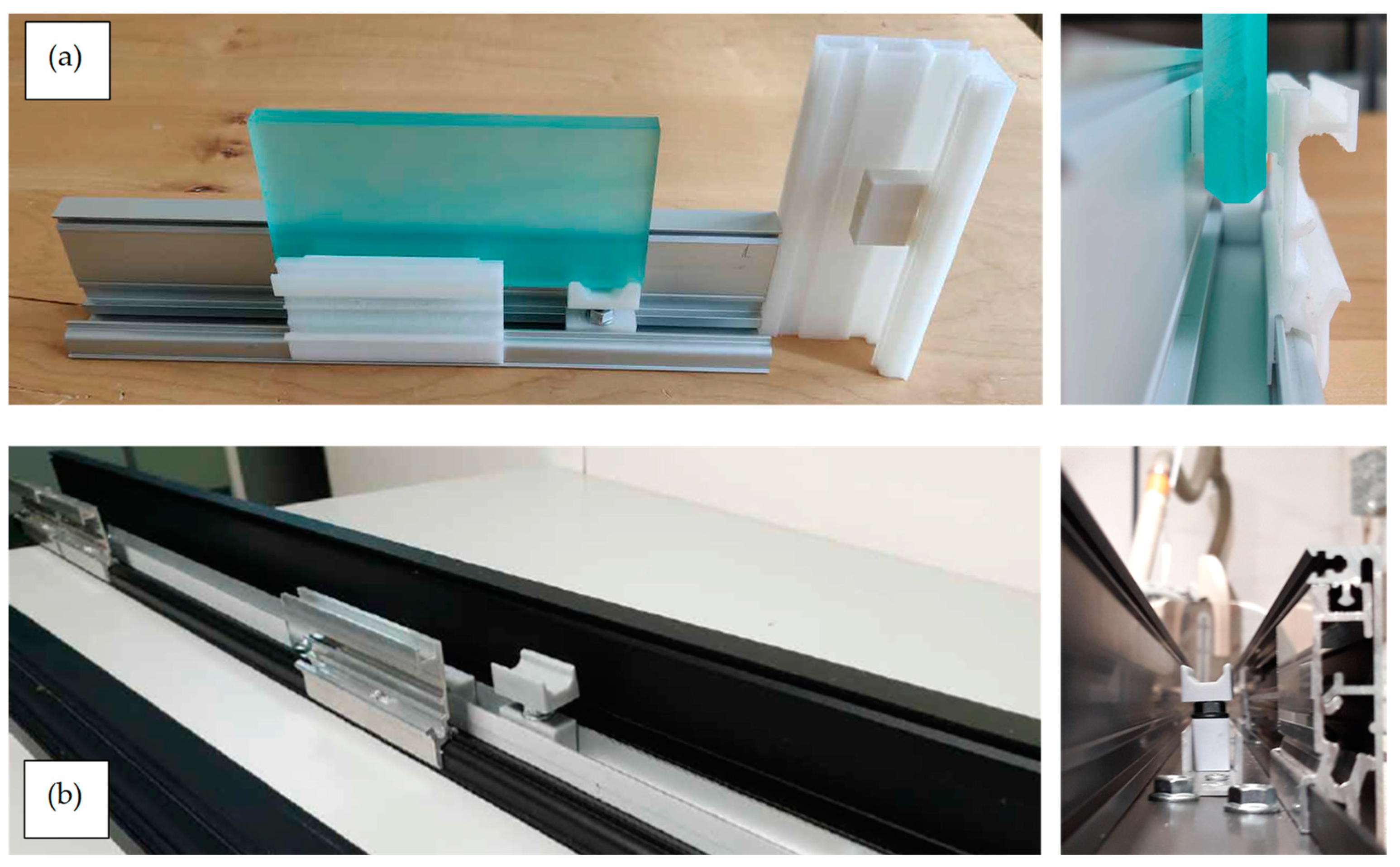
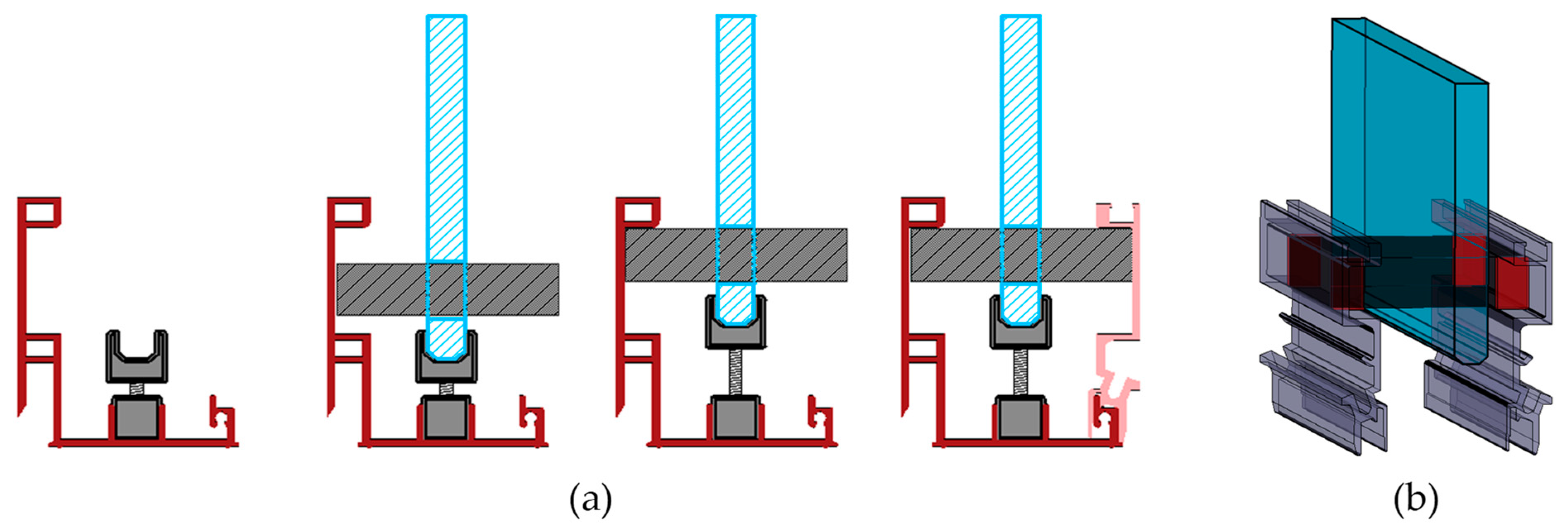
3.2.1. Sliding Supports
3.2.2. Rubber Compounds for the Dissipative Pads
- Premature crisis of the pads was observed at maximum shear strain, γ, equal to 0.7–0.8, i.e., displacement equal to 70–80% of the rubber thickness.
- Impossibility to reduce the thickness of the pads below 15 mm, with repercussions on the dimensions of the profiles that would negatively impact the aesthetic value.
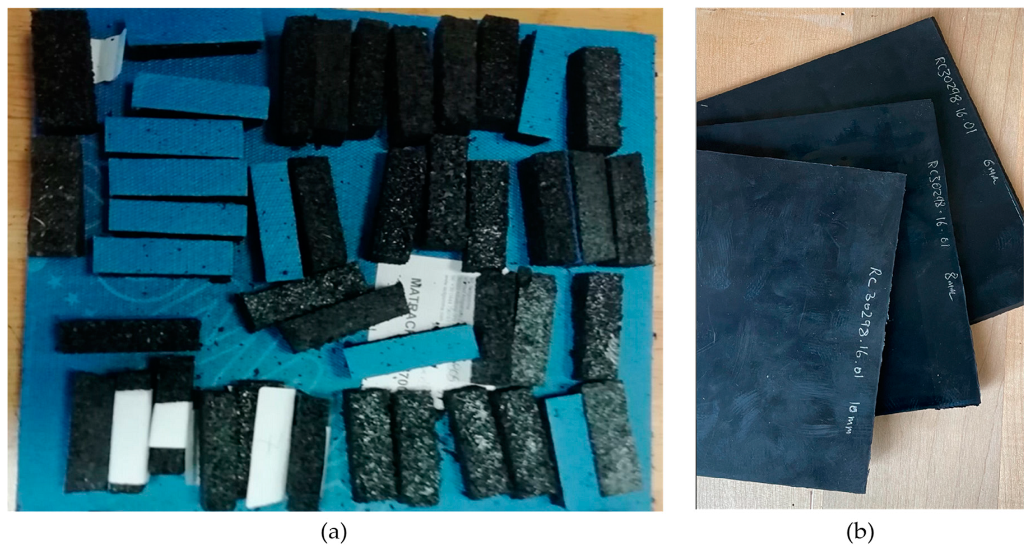
- From visual comparison (Figure 11), it can be noticed how the HDR compound is homogeneous, while the recycled rubber not (larger grain).
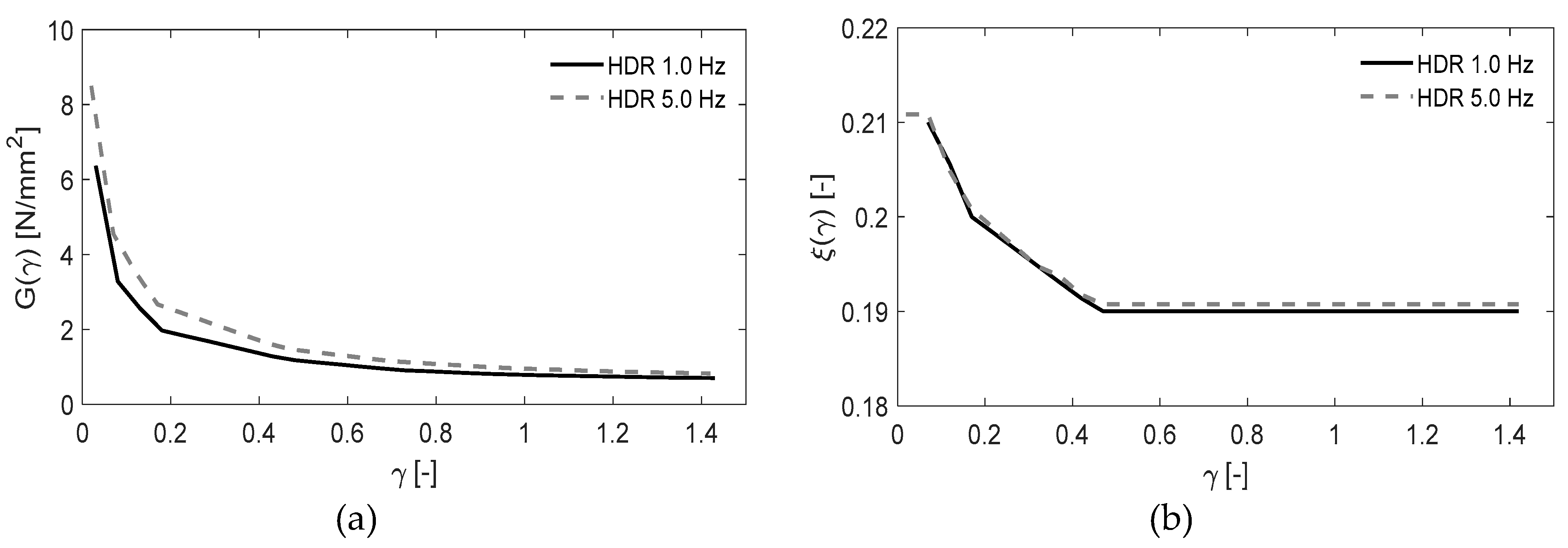
- The HDR compound is considerably stiffer than the recycled rubber, as illustrated in Figure 12a, where the shear modulus function, G(γ), is reported, and this allowed to notably reduce the thickness of the pads below 10 mm, leading to benefits in terms of aluminium profile dimensions.
- Figure 12b shows a comparison between the damping properties of the recycled rubber compound and the HDR compound. It is worth noting that the recycled rubber has negligible dissipative properties for shear strain lower than 0.5, while a larger dissipation was observed for shear strain γ > 0.5 as a consequence of the progressive damage and relevant post-failure friction mechanisms. The damping ratios of the HDR compound are almost two times higher than those of the recycled rubber, and the values remain roughly constant with γ (see ξ(γ) in Figure 12b), with major gains in terms of seismic energy dissipation.
- The strain capacity of the HDR compound is notably greater than the recycled rubber capacity (γ < 0.8). This provided prominent advantages from the point of view of the system safety in case of future extreme events larger than the design ones.
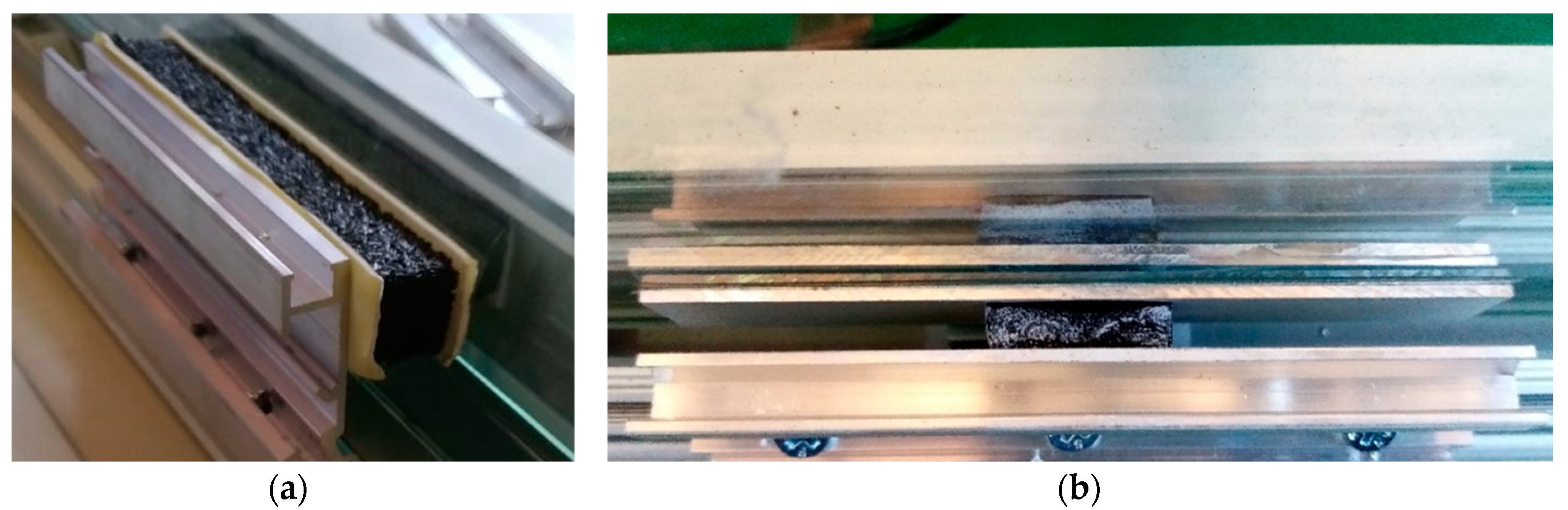
3.2.3. Panel–Pad–Frame Connections
- Adhesive connection via Tesa 64,958 double-sided tape, which revealed poor results in connecting rubber interfaces (surface was too small) but turned out to be good for aluminium–aluminium and aluminium–glass connections.
- Glued connection, where the use of universal glue (Bostik) and cyanoacrylate super-glue (Loctite 480) was investigated. The cyanoacrylate super-glue proved to have very high adhesive performances to connect aluminium–rubber interfaces, while performance notably reduced on rubber–glass interfaces.
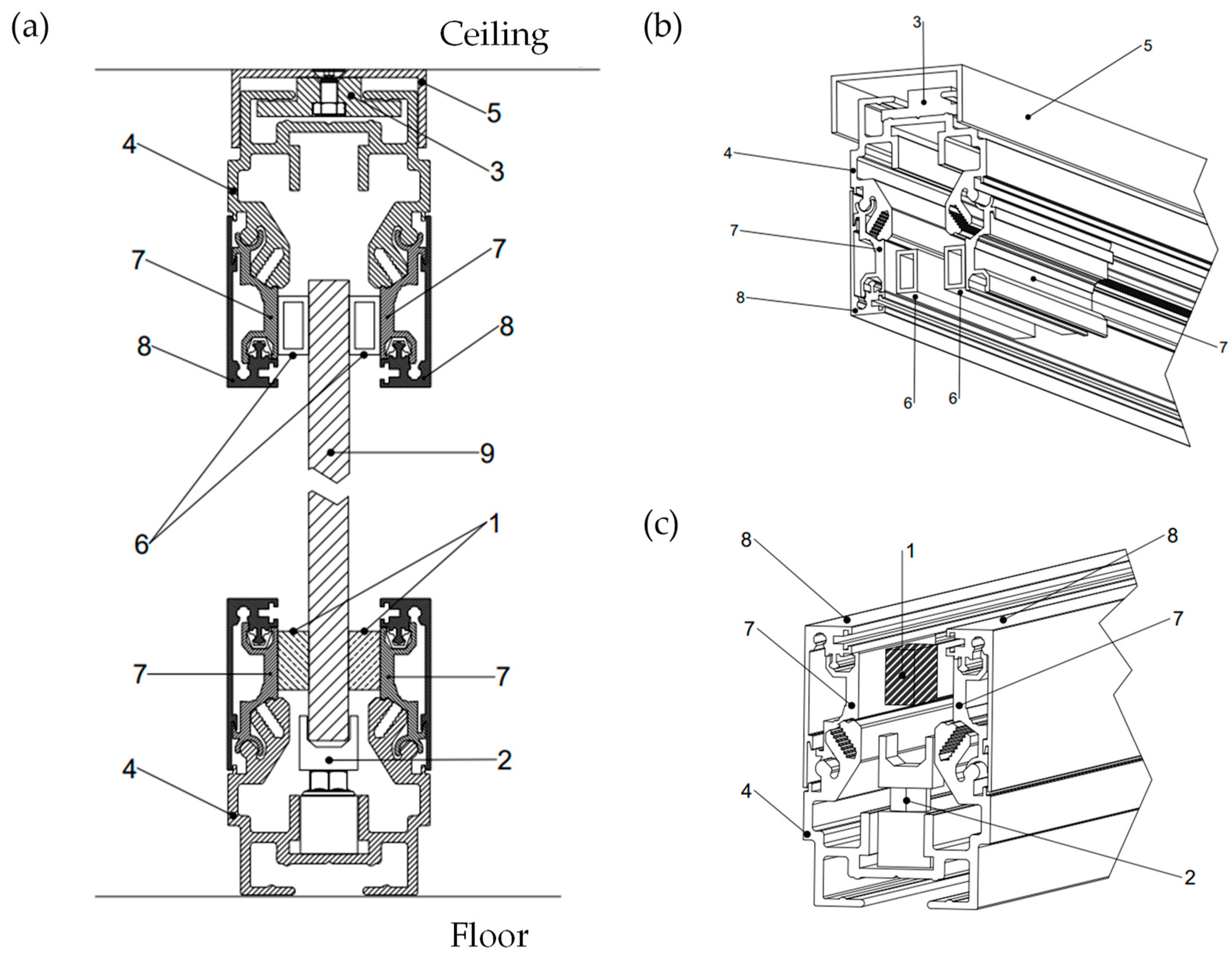
- Accordingly, the following mixed connection was proposed (Figure 13b): a small rectangular aluminium plate was interposed between the glass panel and the rubber pad; the glass-to-aluminium interface was connected via double-sided adhesive tape; the rubber-to-aluminium interface was glued via cyanoacrylate super-glue; on the external side of the profile, i.e., between the pad and aluminium arms (see element 7 in Figure 5), a glued connection was adopted.
- Among the connections that were conceptualised but not tested, one with a potential practical interest is reported in Figure 15, which consisted of an ad-hoc opening on the glass panel, realised to house the rubber pads within it. This solution would eliminate the need for a glued interface between HDR and glass; however, it requires further work on the glass panels to make the necessary holes.
4. Numerical Model Definition and Calibration
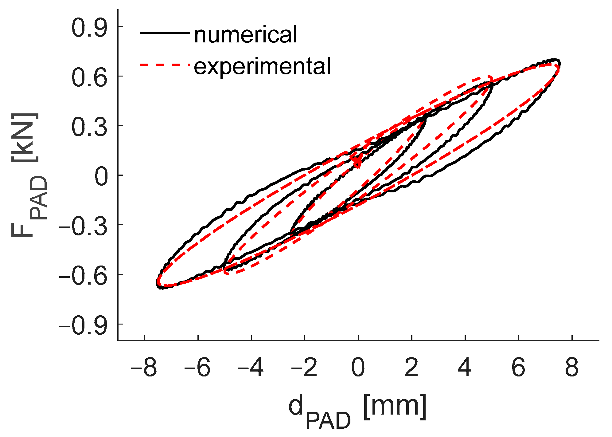
4.1. Rubber Pad Modelling
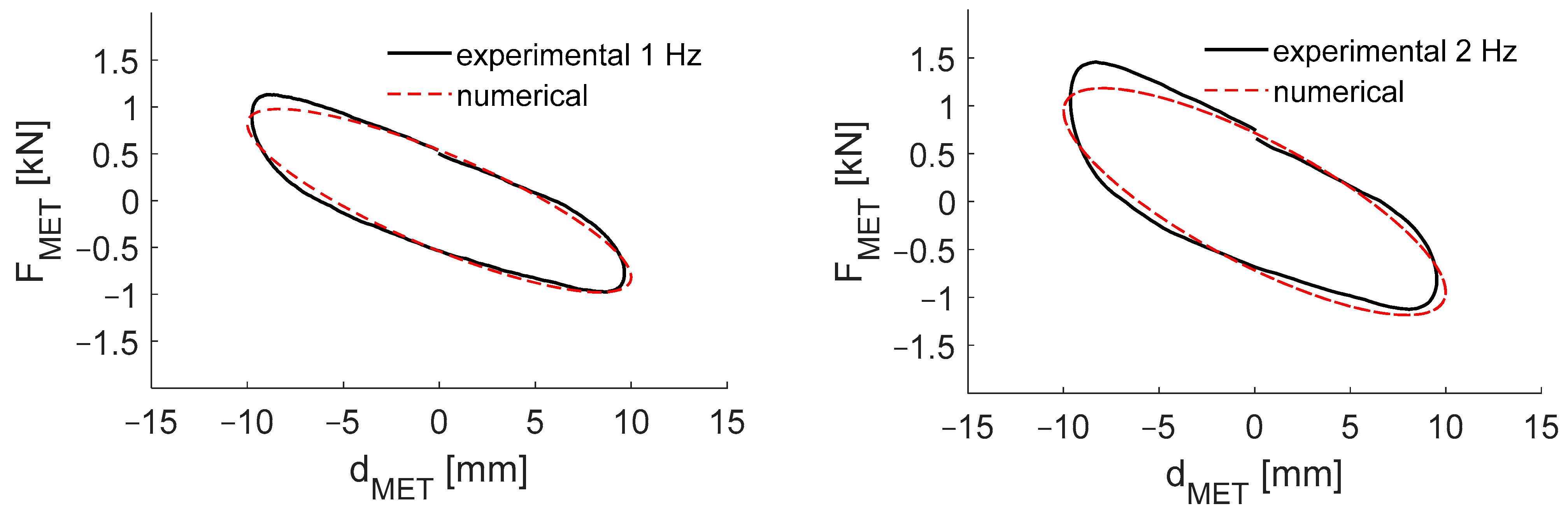
4.2. Methacrylate Joint Modelling
4.3. Small-Scale Experimental Test Modelling
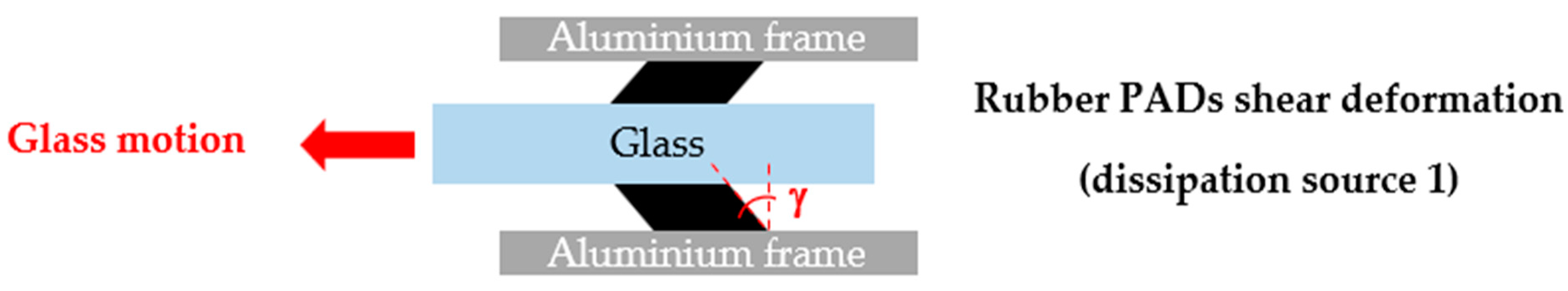
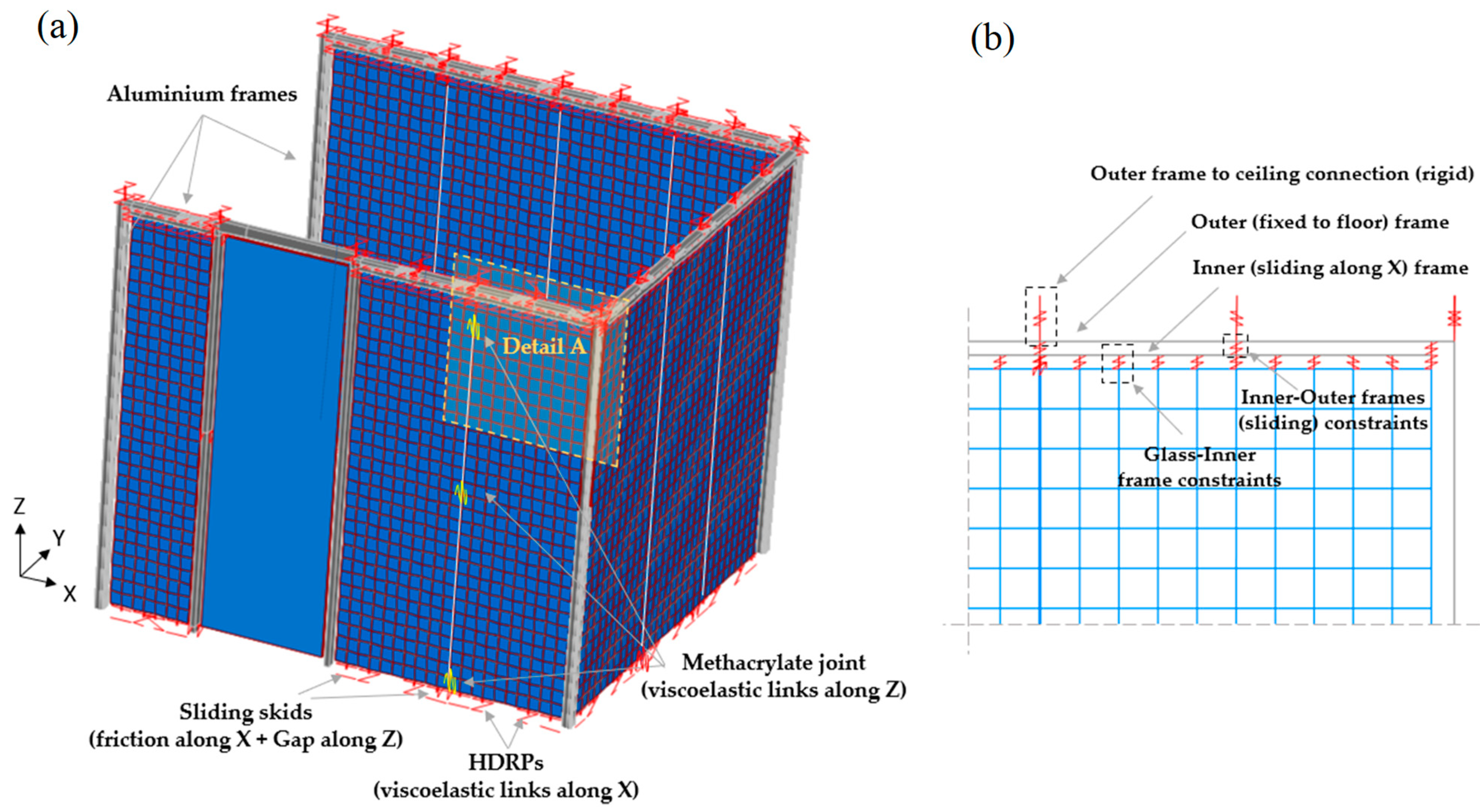
- Rubber pads at the wall base were modelled as viscoelastic links, with equivalent properties calibrated, at proper shear strain levels, γ, based on the results of the mechanical laboratory characterisation.
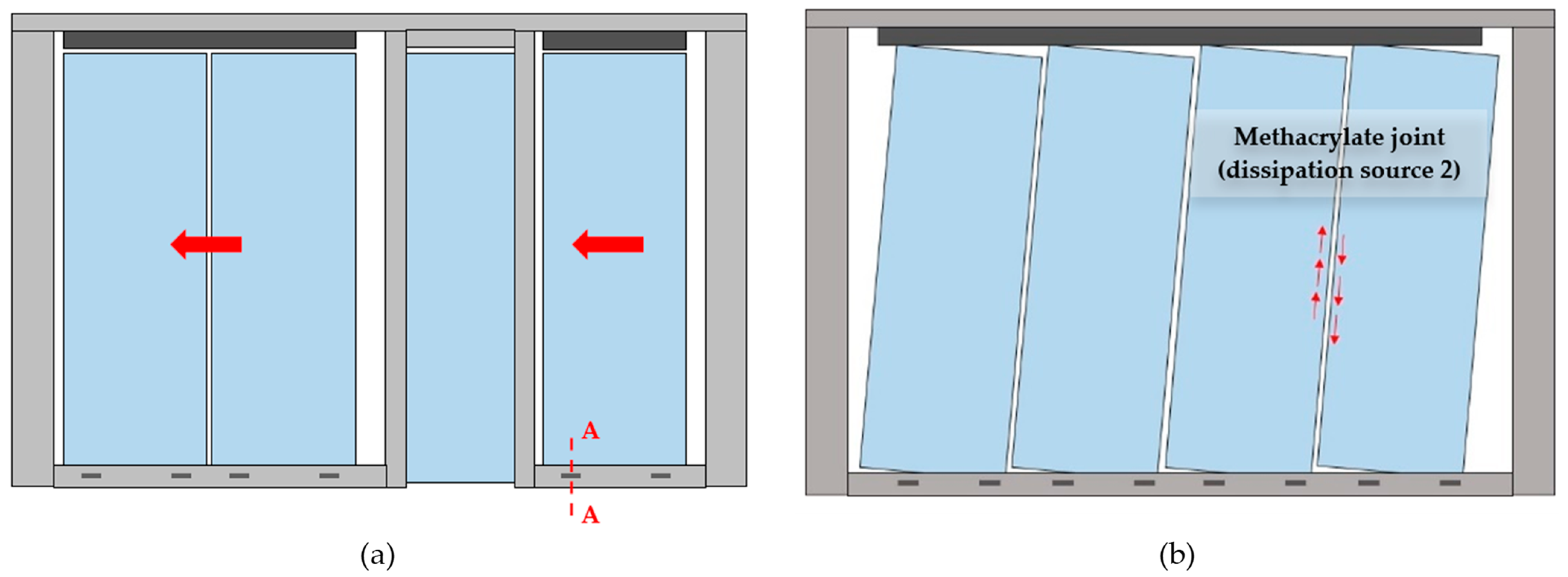
- The methacrylate joint response was modelled by a set of viscoelastic links connecting the adjacent panels and activated by their relative sliding motion (properties derived from experimental tests).
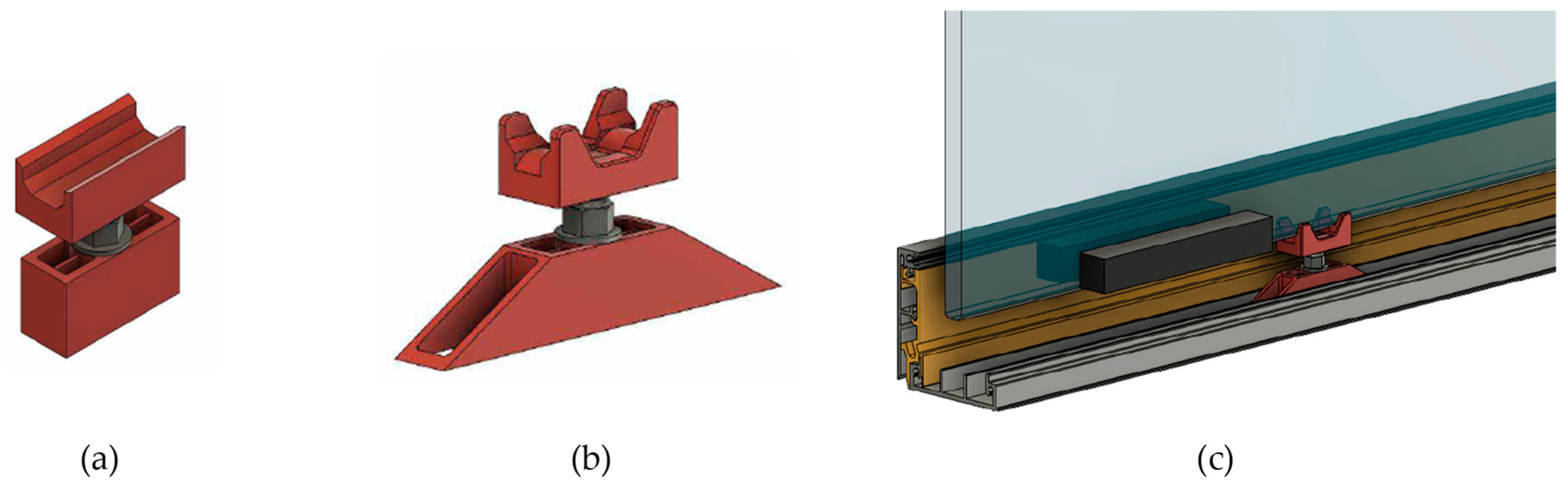
- Sliding skids were inserted at the base of each panel and modelled through link elements (two links per glass panel) with elastoplastic behaviour along the horizontal direction, accounting for the low-friction property (Fmax = 50 N) and having a unilateral constraint property along the vertical direction, i.e., a gap element was adopted to allow contact in compression only, with the possibility of traction detachment of panels from the base supports.
- Each glass plate was individually modelled as an elastic thin shell (10 mm thick) with a distributed mass of 25 kg/m2.
5. Seismic Performances of the Proposed Dissipative Partition Wall within a Building
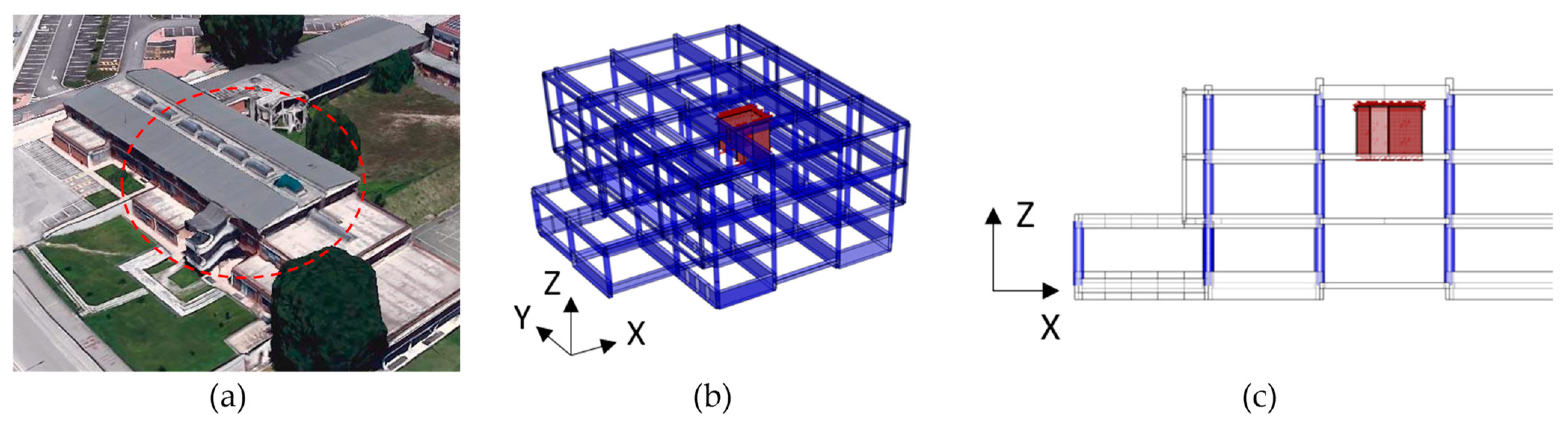
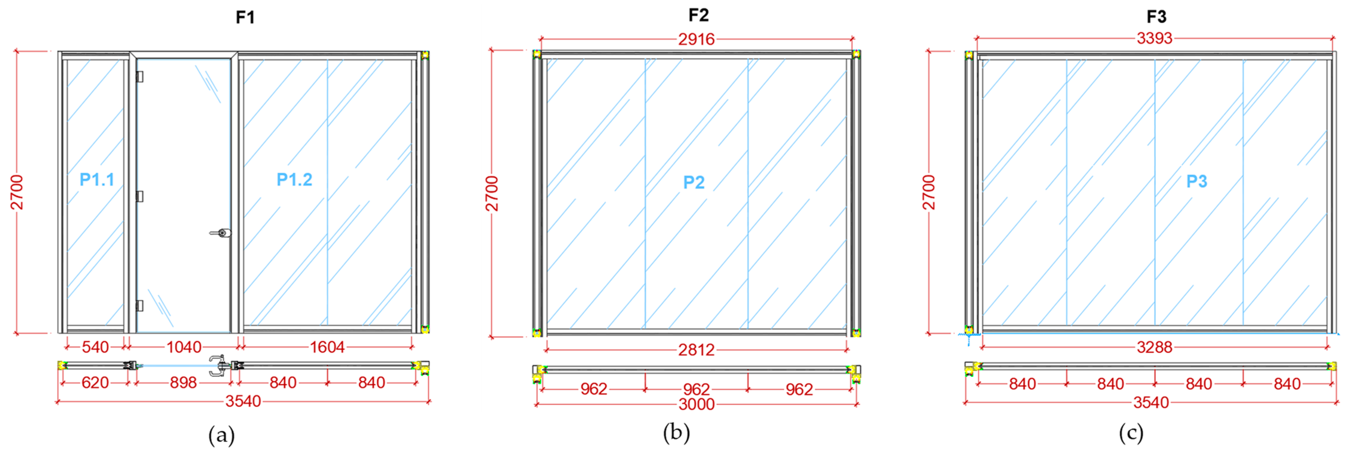
5.1. Case Study Description
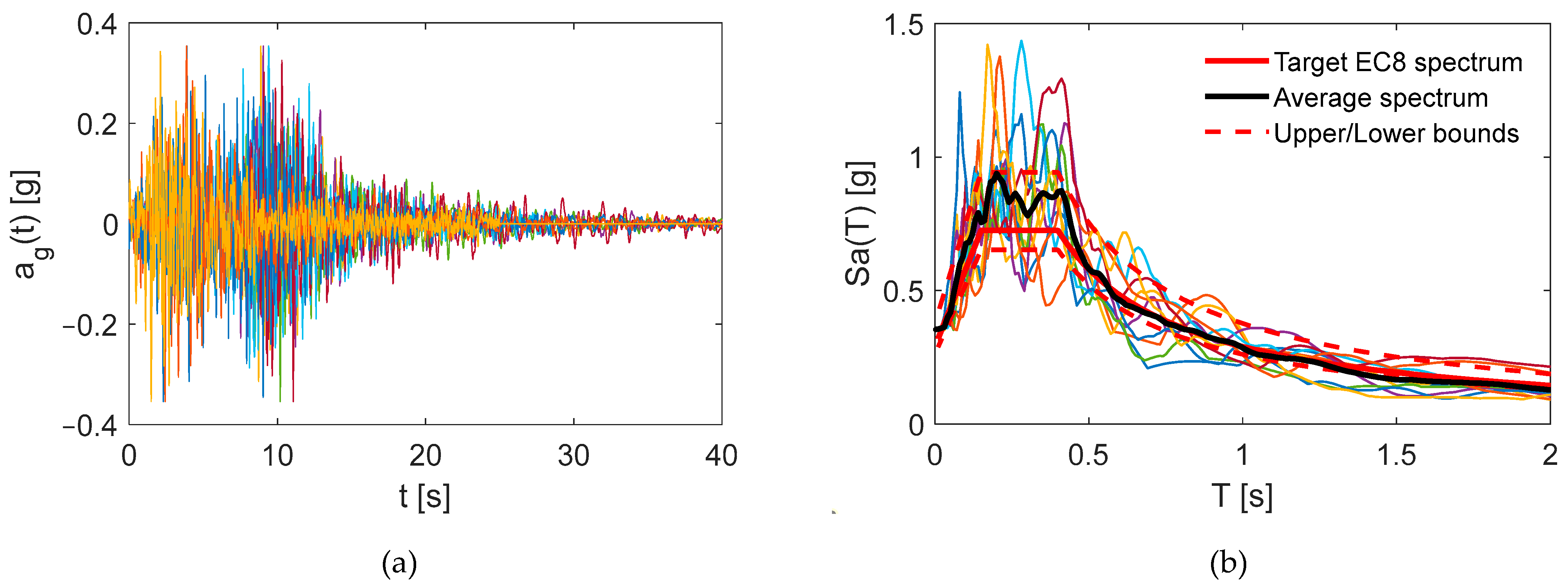
5.2. Seismic Input
5.3. Design of HDRPs
5.4. Numerical Simulations and Performance Evaluation
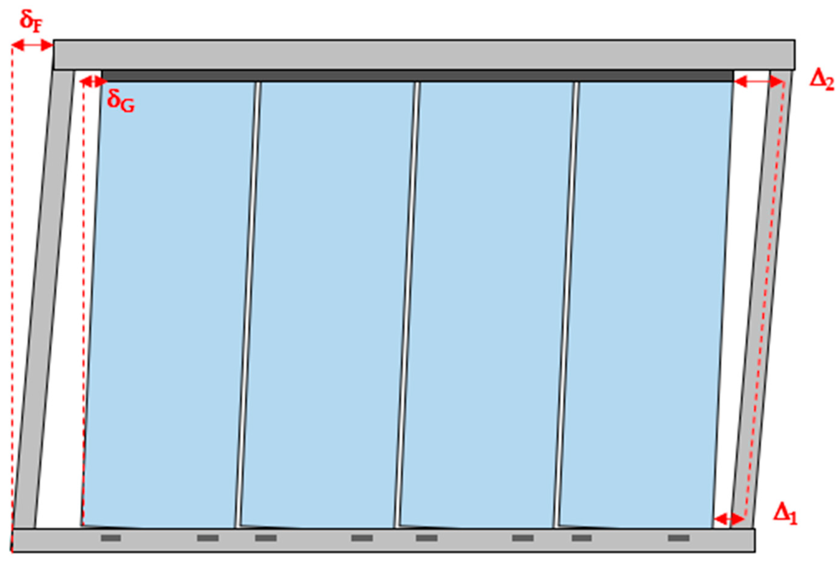
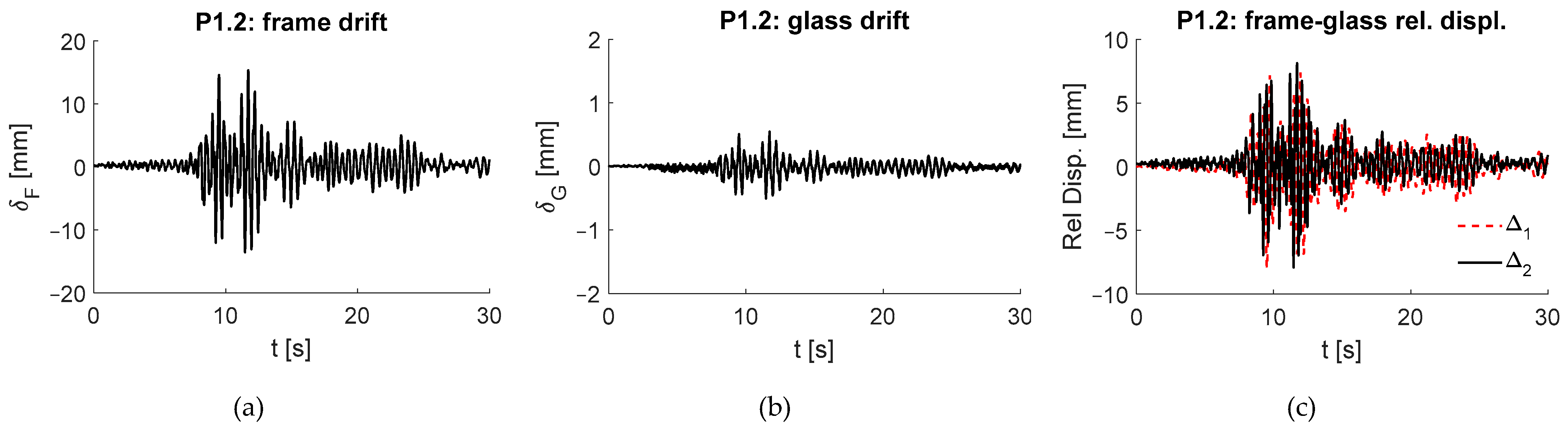
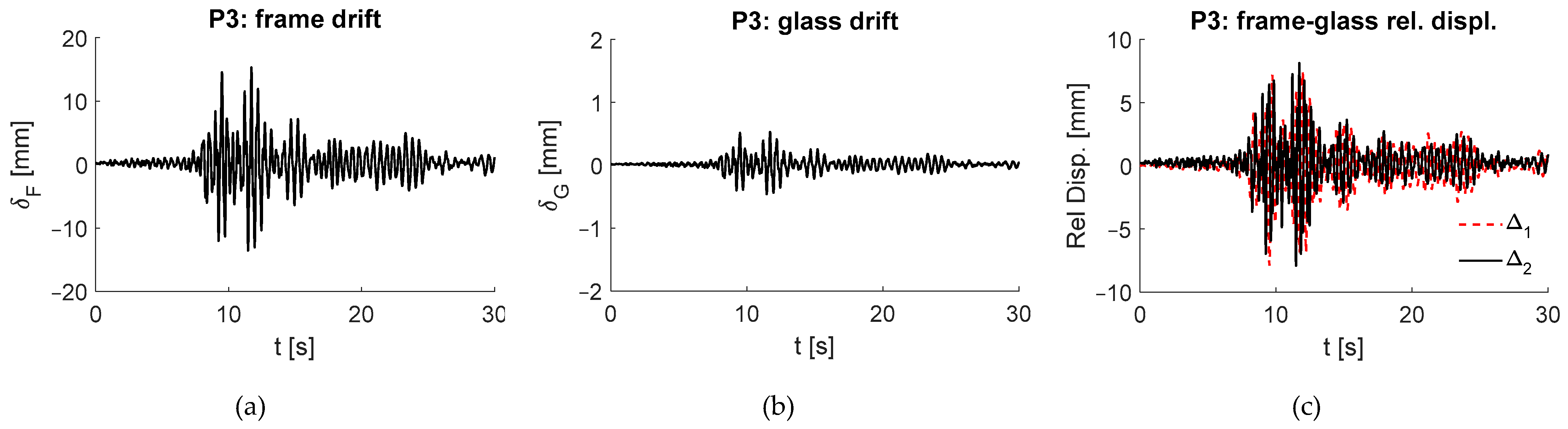
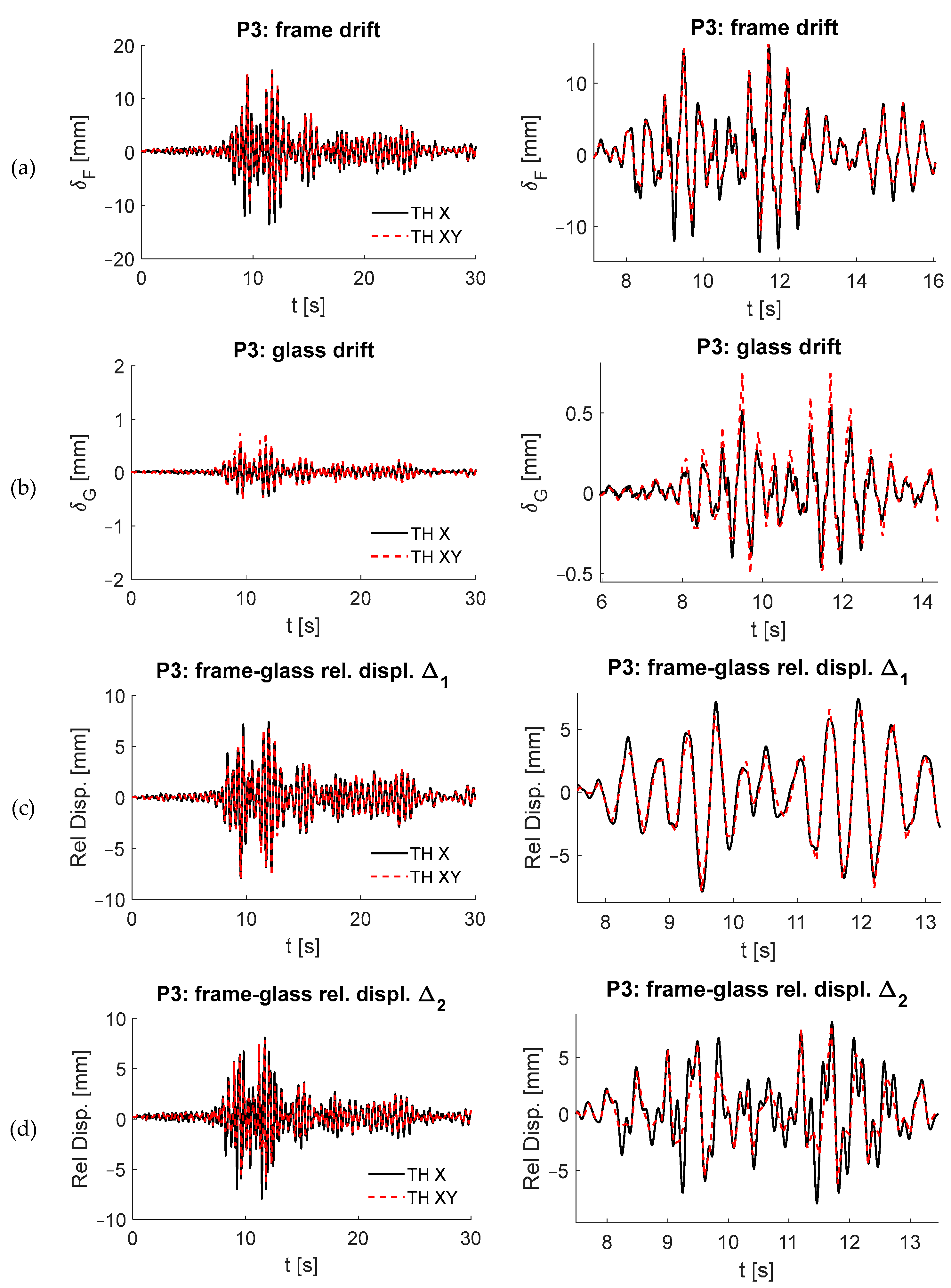
- The relative displacements, δF, experienced by the outer aluminium portal frame (Figure 25a, Figure 26a and Figure 27a) were the same for all the facades, as expected, and they also corresponded to the drift experienced by the building’s last storey (the maximum value, normalised by the third-storey height, attained approximately 0.55%).
- All the panels experienced relative displacements (drift) notably lower than those experienced by the floors (inter-storey drift), and this result is in line with the design objective of making the walls unsensitive to the building drift.
- The motion of the panels P1.2 and P3 appeared mainly translational, with slight rocking components (1 mm maximum) and lateral glass-aluminium relative displacements uniform and synchronous between the top and bottom.
- P1.1, due to its particular configuration, i.e., a single glass plate with a higher slenderness ratio, tended to experience a higher rocking motion (Figure 25b), thus presenting relative displacements between glass and lateral aluminium frames that were higher at the top than at the bottom (Figure 25c), which were, however, always lower than the available stroke of 25 mm (hence, glass–frame pounding was prevented).
- The residual deformations observed on the glass, due to the friction mechanisms at the base of the panels, were of the order of magnitude of a few tenths of a millimetre, and thus definitely acceptable and proof of a good recentring property of the system.
- The clearance of 25 mm left as a safety margin against potential glass–frame pounding was adequate.
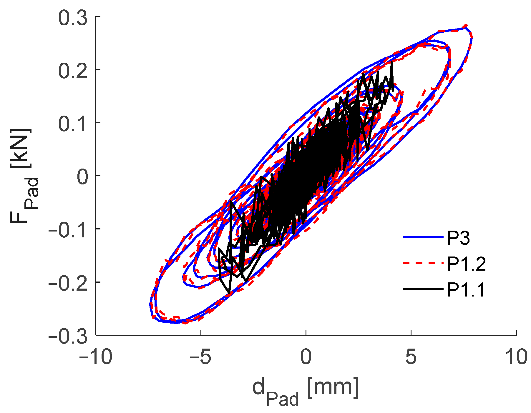
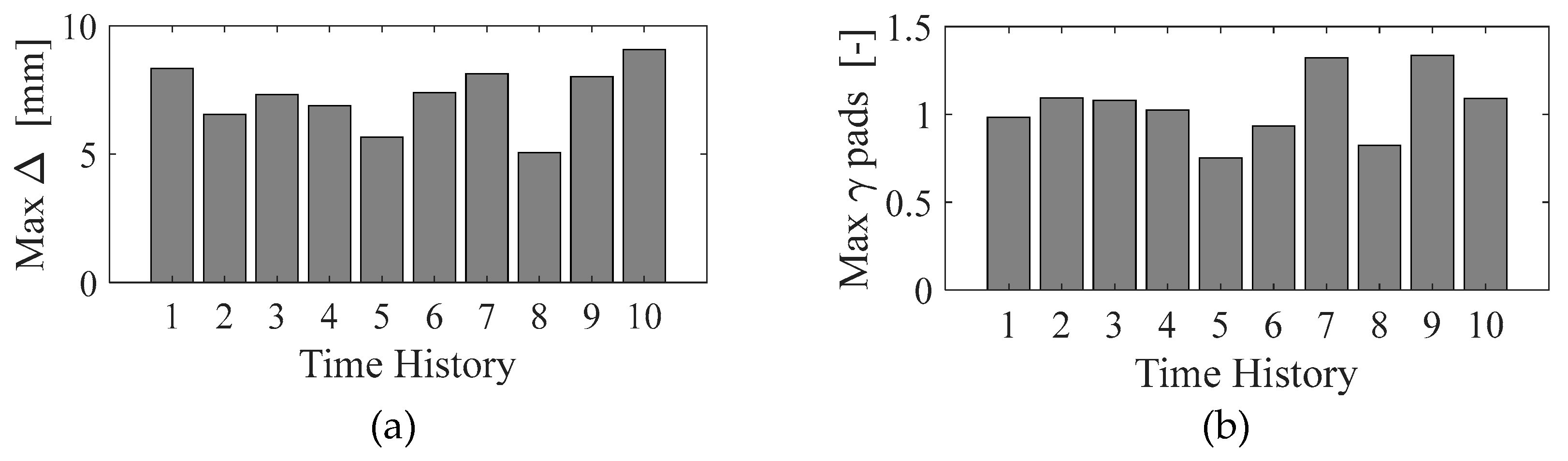
- The pads worked, on average, with a maximum shear strain around γ = 1.0, which is consistent with the design and sufficiently far from the rubber failure (experimentally observed for γ > 2.0).
5.5. Connection to the Ceiling
5.6. Effect of the Cladding Walls on the Hosting Building
6. Conclusions
Author Contributions
Funding
Data Availability Statement
Acknowledgments
Conflicts of Interest
References
- Villaverde, R. Seismic Analysis and Design of Nonstructural Elements. In Earthquake Engineering: From Engineering Seismology to Performance-Based Engineering; Bozorgnia, Y., Bertero, V., Eds.; CRC Press: Boca Raton, FL, USA, 2004. [Google Scholar]
- Hashemi, A.; Mosalam, K.M. Shake-table experiment on reinforced concrete structure containing masonry infill wall. Earthq. Eng. Struct. Dyn. 2006, 35, 1827–1852. [Google Scholar] [CrossRef]
- Dolšek, M.; Fajfar, P. The effect of masonry infills on the seismic response of a four-storey reinforced concrete frame—A deterministic assessment. Eng. Struct. 2008, 30, 1991–2001. [Google Scholar] [CrossRef]
- Stavridis, A.; Koutromanos, I.; Shing, P.B. Shake-table tests of a three-story reinforced concrete frame with masonry infill walls. Earthq. Eng. Struct. Dyn. 2012, 41, 1089–1108. [Google Scholar] [CrossRef]
- Uva, G.; Porco, F.; Fiore, A. Appraisal of masonry infill walls effect in the seismic response of RC framed buildings: A case study. Eng. Struct. 2012, 34, 514–526. [Google Scholar] [CrossRef]
- De Luca, F.; Verderame, G.M.; Gómez-Martínez, F.; Pérez-García, A. The structural role played by masonry infills on RC building performances after the 2011 Lorca, Spain, earthquake. Bull. Earthq. Eng. 2014, 12, 1999–2026. [Google Scholar] [CrossRef]
- Ricci, P.; Di Domenico, M.; Verderame, G.M. Experimental assessment of the in-plane/out-of-plane interaction in unreinforced masonry infill walls. Eng. Struct. 2018, 173, 960–978. [Google Scholar] [CrossRef]
- De Matteis, G.; Landolfo, L.; Mazzolani, F.M. Diaphragm effect for industrial steel buildings under earthquake loading. J. Constr. Steel Res. 1998, 46, 357–358. [Google Scholar] [CrossRef]
- De Matteis, G. Effect of lightweight cladding panels on the seismic performance of moment resisting steel frames. Eng. Struct. 2005, 27, 1662–1676. [Google Scholar] [CrossRef]
- Okazaki, T.; Nakashima, M.; Suita, K.; Matusmiya, T. Interaction between cladding and structural frame observed in a full-scale steel building test. Earthq. Eng.Struct. Dyn. 2007, 36, 35–53. [Google Scholar] [CrossRef]
- Mastrogiuseppe, S.; Rogers, C.A.; Tremblay, R.; Nedisan, C.D. Influence of nonstructural components on roof diaphragm stiffness and fundamental periods of single-storey steel buildings. J. Constr. Steel Res. 2008, 64, 214–227. [Google Scholar] [CrossRef]
- Scozzese, F.; Terracciano, G.; Zona, A.; Della Corte, G.; Dall’Asta, A.; Landolfo, R. Analysis of seismic non-structural damage in single-storey industrial steel buildings. Soil Dyn. Earthq. Eng. 2018, 114, 505–519. [Google Scholar] [CrossRef]
- Dhakal, R.P. Damage to non-structural components and contents in 2010 darfield earthquake. Bull. N. Z. Soc. Earthq. Eng. 2010, 43, 404–410. [Google Scholar] [CrossRef]
- Taghavi, S.; Miranda, E. Response Assessment of Nonstructural Building Elements. Report 2003/05; Pacific Earthquake Engineering Research (PEER) Centre: Berkley, CA, USA, 2003; p. 96. [Google Scholar]
- Khakurel, S.; Dhakal, R.P.; Yeow, T.; Saha, S. Performance group weighting factors for rapid seismic loss estimation of buildings of different usage. Earthq. Spectra. 2020, 36, 1141–1165. [Google Scholar] [CrossRef]
- Bradley, B.A.; Dhakal, R.P.; Cubrinovski, M.; MacRae, G.A. Seismic loss estimation for efficient decision making. Bull. N. Z. Soc. Earthq. Eng. 2009, 42, 96–110. [Google Scholar] [CrossRef]
- Dhakal, R.P.; Pourali, A.; Saha, S. Simplified seismic loss functions for suspended ceilings and drywall partitions. Bull. N. Z. Soc. Earthq. Eng. 2016, 49, 64–78. [Google Scholar] [CrossRef]
- Sousa, L.; Monteiro, R. Seismic retrofit options for non-structural building partition walls: Impact on loss estimation and cost-benefit analysis. Eng. Struct. 2018, 161, 8–27. [Google Scholar] [CrossRef]
- Takagi, J.; Wada, A. Recent earthquakes and the need for a new philosophy for earthquake-resistant design. Soil Dyn. Earthq. Eng. 2019, 119, 499–507. [Google Scholar] [CrossRef]
- Arifin, F.A.; Sullivan, T.J.; MacRae, G.; Kurata, M.; Takeda, T. Lessons for loss assessment from the Canterbury earthquakes: A 22-storey building. Bull. Earthq. Eng. 2021, 19, 2081–2104. [Google Scholar] [CrossRef]
- O’Reilly, G.J.; Hasegawa, K.; Shahnazaryan, D.; Poveda, J.; Fukutomi, Y.; Kusaka, A.; Nakashima, M. On the fragility of non-structural elements in loss and recovery: Field observations from Japan. Earthq. Eng. Struct. Dyn. 2024, 53, 1125–1144. [Google Scholar] [CrossRef]
- Ahmad, Z.; Ahmed, H.A.; Shahzada, K.; Li, Y. Vulnerability of Non-Structural Elements (NSEs) in Buildings and Their Life Cycle Assessment: A Review. Buildings 2024, 14, 170. [Google Scholar] [CrossRef]
- Preti, M.; Bettini, N.; Migliorati, L.; Bolis, V.; Stavridis, A.; Plizzari, G.A. Analysis of the in-plane response of earthen masonry infill panels partitioned by sliding joints. Earthq. Eng. Struct. Dyn. 2016, 45, 1209–1232. [Google Scholar] [CrossRef]
- Palios, X.; Fardis, M.N.; Strepelias, E.; Bousias, S.N. Unbonded brickwork for the protection of infills from seismic damage. Eng. Struct. 2017, 131, 614–624. [Google Scholar] [CrossRef]
- Tsantilis, A.V.; Triantafillou, T.C. Innovative seismic isolation of masonry infills using cellular materials at the interface with the surrounding RC frames. Eng. Struct. 2018, 155, 279–297. [Google Scholar] [CrossRef]
- Marinković, M.; Butenweg, C. Innovative decoupling system for the seismic protection of masonry infill walls in reinforced concrete frames. Eng. Struct. 2019, 197, 09435. [Google Scholar] [CrossRef]
- Dhir, P.K.; Tubaldi, E.; Ahmadi, H.; Gough, J. Numerical modelling of reinforced concrete frames with masonry infills and rubber joints. Eng. Struct. 2021, 246, 112833. [Google Scholar] [CrossRef]
- Dhir, P.K.; Tubaldi, E.; Panto, B.; Calio, I. A macro-model for describing the in-plane seismic response of masonry-infilled frames with sliding/flexible joints. Earthq. Eng.Struct. Dyn. 2022, 51, 3022–3044. [Google Scholar] [CrossRef]
- Lee, T.H.; Kato, M.; Matsumiya, T.; Suita, K.; Nakashima, M. Seismic performance evaluation of non-structural components: Drywall partitions. Earthq. Eng. Struct. Dyn. 2007, 36, 367–382. [Google Scholar] [CrossRef]
- Restrepo, J.I.; Bersofsky, A.M. Performance characteristics of light gage steel stud partition walls. Thin-Walled Struct. 2011, 49, 317–324. [Google Scholar] [CrossRef]
- Retamales, R.; Davies, R.; Mosqueda, G.; Filiatrault, A. Experimental seismic fragility of cold-formed steel framed gypsum partition walls. J. Struct. Eng. 2013, 139, 1285–1293. [Google Scholar] [CrossRef]
- Magliulo, G.; Petrone, C.; Capozzi, V.; Maddaloni, G.; Lopez, P.; Manfredi, G. Seismic performance evaluation of plasterboard partitions via shake table tests. Bull. Earthq. Eng. 2013, 12, 1657–1677. [Google Scholar] [CrossRef]
- Tasligedik, A.S.; Pampanin, S.; Palermo, A. Low damage seismic solutions for non-structural drywall artitions. Bull. Earthq. Eng. 2014, 13, 1029–1050. [Google Scholar] [CrossRef]
- Wang, X.; Pantoli, E.; Hutchinson, T.C.; Restrepo, J.I.; Wood, R.L.; Hoehler, M.S.; Grzesik, P.; Sesma, F.H. Seismic performance of cold-formed steel wall systems in a full-scale building. J. Struct. Eng. 2015, 141, 04015014. [Google Scholar] [CrossRef]
- Rahmanishamsi, E.; Soroushian, S.; Maragakis, E. Analytical model for the in-plane seismic performance of cold-formed steel-framed gypsum partition walls. Earthq. Eng. Struct. Dyn. 2015, 45, 619–634. [Google Scholar] [CrossRef]
- Petrone, C.; Magliulo, G.; Lopez, P.; Manfredi, G. Seismic fragility of plasterboard partitions via in-plane quasi-static tests. Earthq. Eng. Struct. Dyn. 2015, 44, 2589–2606. [Google Scholar] [CrossRef]
- Petrone, C.; Magliulo, G.; Lopez, P.; Manfredi, G. Out-of-plane seismic performance of plasterboard partitions via quasi-static tests. Bull. N. Z. Soc. Earthq. Eng. 2016, 49, 125–137. [Google Scholar] [CrossRef]
- Jenkins, C.; Soroushian, S.; Rahmanishamsi, E.; Maragakis, E.M. Experimental fragility analysis of cold-formed steel-framed partition wall systems. Thin-Walled Struct. 2016, 103, 115–127. [Google Scholar] [CrossRef]
- Rahmanishamsi, E.; Soroushian, S.; Maragakis, E.M. Cyclic shear behavior of gypsum board-to-steel stud screw connections in nonstructural walls. Earthq. Spectra. 2016, 32, 415–439. [Google Scholar] [CrossRef]
- Rahmanishamsi, E.; Soroushian, S.; Maragakis, E.M. Evaluation of the out-of-plane behavior of stud-to-track connections in nonstructural partition walls. Thin-Walled Struct. 2016, 103, 211–224. [Google Scholar] [CrossRef]
- Rahmanishamsi, E.; Soroushian, S.; Maragakis, E.M. Analytical model to capture the in-plane and out-of-plane seismic behavior of nonstructural partition walls with returns. J. Struct. Eng. 2017, 143, 6. [Google Scholar] [CrossRef]
- Petrone, C.; Magliulo, G.; Manfredi, G. Shake table tests on standard and innovative temporary partition walls. Earthq. Eng. Struct. Dyn. 2017, 46, 1599–1624. [Google Scholar] [CrossRef]
- Petrone, C.; Coppola, O.; Magliulo, G.; Lopez, P.; Manfredi, G. Numerical model for the in-plane seismic capacity evaluation of tall plasterboard internal partitions. Thin-Walled Struct. 2018, 122, 572–584. [Google Scholar] [CrossRef]
- Fiorino, L.; Pali, T.; Landolfo, R. Out-of-plane seismic design by testing of non-structural lightweight steel drywall partition walls. Thin-Walled Struct. 2018, 130, 213–230. [Google Scholar] [CrossRef]
- Pali, T.; Macillo, V.; Terracciano, M.T.; Bucciero, B.; Fiorino, L.; Landolfo, R. In-plane quasi-static cyclic tests of nonstructural lightweight steel drywall partitions for seismic performance evaluation. Earthq. Eng. Struct. Dyn. 2018, 47, 1566–1588. [Google Scholar] [CrossRef]
- Fiorino, L.; Bucciero, B.; Landolfo, R. Evaluation of seismic dynamic behaviour of drywall partitions, façades and ceilings through shake table testing. Eng. Struct. 2019, 180, 103–123. [Google Scholar] [CrossRef]
- Araya-Letelier, G.; Miranda, E.; Deierlein, G. Development and Testing of a Friction/Sliding Connection to Improve the Seismic Performance of Gypsum Partition Walls. Earthq. Spectra. 2019, 35, 653–677. [Google Scholar] [CrossRef]
- Mulligan, J.; Sullivan, T.; Dhakal, R. Experimental Seismic Performance of Partly-Sliding Partition Walls. J. Earthq. Eng. 2020, 26, 1630–1655. [Google Scholar] [CrossRef]
- Mulligan, J.; Sullivan, T.; Dhakal, R. Experimental study of the seismic performance of plasterboard partition walls with seismic gaps. Bull. N. Z. Soc. Earthq. Eng. 2020, 53, 175–188. [Google Scholar] [CrossRef]
- Salmasi Javid, H.; Soroushian, S.; Rahmanishamsi, E.; Maragakis, E.M. Methodology for the Development of Analytical Seismic Fragility for Full Connection Steel-Framed Gypsum Partition Walls. J. Earthq. Eng. 2020, 26, 4129–4146. [Google Scholar] [CrossRef]
- Shin, D.-H.; Kim, H.-J. Macro-modelling approach for the in-plane cyclic response of cold-formed steel partition walls. Appl. Sci. 2020, 10, 8163. [Google Scholar] [CrossRef]
- Kim, H.J.; Shin, D.H. Shake table test program of cold-formed steel in-plane partition walls. Structures 2021, 30, 503–517. [Google Scholar] [CrossRef]
- Wang, D.; Zhi, X.; Zhu, F.; Wang, Y. Seismic Fragility of Chinese Light-Gauge Steel Keel Gypsum Board Partition Walls. Shock. Vib. 2021, 2021, 8875486. [Google Scholar] [CrossRef]
- Lotfy, I.; Salkhordeh, M.; Soroushian, S.; Rahmanishamsi, E.; Maragakis, E.M. Development of the simplified spring-based nonlinear models for full-connection cold-formed steel-framed gypsum partition walls. Earthq. Eng. Struct. Dyn. 2023, 52, 1317–1338. [Google Scholar] [CrossRef]
- Huang, J.; Kurata, M.; Shen, S.-D. Experimental investigation and modeling of boundary influences on in-plane seismic performance of partition walls. Earthq. Eng. Struct. Dyn. 2024, 53, 924–942. [Google Scholar] [CrossRef]
- Huang, J.; Kurata, M.; Kawamata, Y.; Kanao, I.; Qi, L.; Takaoka, M. In-Plane damage of partition walls with various boundaries during earthquakes. Earthq. Eng. Struct. Dyn. 2023, 52, 1059–1077. [Google Scholar] [CrossRef]
- Ditommaso, R.; Scozzese, F.; Mossucca, A.; Auletta, G.; Di Cesare, A.; Nigro, D.; Zona, A.; Ponzo, F.C.; Dall’Asta, A. Preliminary results in the design and testing of earthquake-proof glass-aluminium partition walls. In Proceeding of the 17th World Conference on Seismic Isolation ASSISI, Turin, Italy, 12–15 September 2022. [Google Scholar] [CrossRef]
- Scozzese, F.; Ditommaso, R.; Zona, A.; Ponzo, F.C.; Di Cesare, A.; Dall’Asta, A. Earthquake-proof glass-aluminium partition walls with viscoelastic dissipative devices. In Proceeding of the 18th World Conference on Earthquake Engineering (WCEE2024), Milan, Italy, 30 June–5 July 2024. [Google Scholar]
- Payne, A.R. The dynamic properties of carbon black-loaded natural rubber vulcanizates. Part, I.J. Appl. Polym. Sci. 1962, 6, 57–63. [Google Scholar] [CrossRef]
- Lion, A. A constitutive model for carbon black filled rubber: Experimental investigation and mathematical representation. Contin. Mech. Thermodyn. 1996, 8, 153–169. [Google Scholar] [CrossRef]
- Tubaldi, E.; Ragni, L.; Dall’Asta, A.; Ahmadi, H.; Muhr, A. Stress softening behaviour of HDNR bearings: Modelling and influence on the seismic response of isolated structures. Earthq. Eng. Struct. Dyn. 2017, 46, 2033–2054. [Google Scholar] [CrossRef]
- Micozzi, F.; Scozzese, F.; Ragni, L.; Dall’Asta, A. Seismic reliability of base isolated systems: Sensitivity to design choices. Eng. Struct. 2022, 256, 114056. [Google Scholar] [CrossRef]
- Xian, W.; Zhan, Y.-S.; Maiti, A.; Saab, A.P.; Li, Y. Filled Elastomers: Mechanistic and Physics-Driven Modeling and Applications as Smart Materials. Polymers 2024, 16, 1387. [Google Scholar] [CrossRef]
- Xu, Z.D.; Xu, C.; Hu, J. Equivalent fractional Kelvin model and experimental study on viscoelastic damper. J. Vib. Control 2015, 21, 2536–2552. [Google Scholar] [CrossRef]
- Xu, Z.D.; Liao, Y.X.; Ge, T.; Xu, C. Experimental and theoretical study of viscoelastic dampers with different matrix rubbers. J. Eng. Mech. 2016, 142, 04016051. [Google Scholar] [CrossRef]
- Xu, Z.D.; Ge, T.; Liu, J. Experimental and theoretical study of high-energy dissipation-viscoelastic dampers based on acrylate-rubber matrix. J. Eng. Mech. 2020, 146, 04020057. [Google Scholar] [CrossRef]
- Dall’Asta, A.; Ragni, L. Experimental Tests and Analytical Model of High Damping Rubber Dissipating Devices. Eng. Struct. 2006, 28, 1874–1884. [Google Scholar] [CrossRef]
- SAP2000, Ultimate Version 25.3.0.; Integrated Finite Element Analysis and Design of Structures; Computers and Structures Inc.: Berkeley, CA, USA, 2024.
- Dall’Asta, A.; Ragni, L. Dynamic systems with high damping rubber: Nonlinear behaviour and linear approximation. Earthq. Eng. Struct. Dyn. 2008, 37, 1511–1526. [Google Scholar] [CrossRef]
- Micozzi, F.; Ragni, L.; Gioiella, L.; Quaglini, V.; Dall’Asta, A. Variability of Dynamic Properties of Rubber Compounds for Elastomeric Bearings. Struct. Control. Health Monit. 2023, 1, 6638748. [Google Scholar] [CrossRef]
- Federal Emergency Management Agency (FEMA). NEHRP Commentary on the Guidelines for the Seismic Rehabilitation of Buildings, FEMA Publication 274; Federal Emergency Management Agency: Washington, DC, USA, 1997.
- Mazzolani, F. Aluminium Alloy Structures, 2nd ed.; CRC Press: Boca Raton, FL, USA, 2019. [Google Scholar]
- Brandolese, S.; Fiorin, L.; Scotta, R. Seismic demand and capacity assessment of suspended ceiling systems. Eng. Struct. 2019, 193, 219–237. [Google Scholar] [CrossRef]


| γmax (-) | D (mm) | keff (N/mm) | ξeff (-) | Ceq (Ns/mm) |
|---|---|---|---|---|
| 0.17 | 2.5 | 145.00 | 0.12 | 5.54 |
| 0.33 | 5.0 | 116.00 | 0.13 | 4.62 |
| 0.50 | 7.5 | 86.00 | 0.14 | 3.83 |
| Frequency (Hz) | keff (N/mm) | Ceq (Ns/mm) | α (-) |
|---|---|---|---|
| 1.0 | 80.0 | 18.0 | 1.0 |
| 2.0 | 90.0 | 12.0 | 1.0 |
| Response Parameter | X Direction | XY Directions |
|---|---|---|
| Max. γ HDRP | 1.42 | 1.50 |
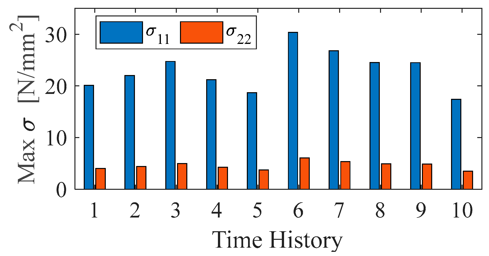
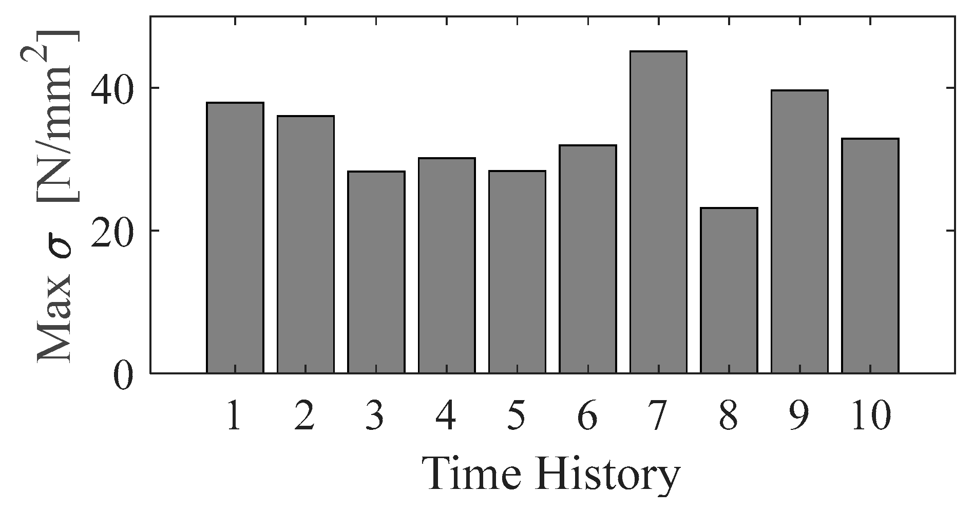
| Max. σ glass (MPa) | 27 | 25 |
| Max. σ aluminium (MPa) | 30 | 34 |
Disclaimer/Publisher’s Note: The statements, opinions and data contained in all publications are solely those of the individual author(s) and contributor(s) and not of MDPI and/or the editor(s). MDPI and/or the editor(s) disclaim responsibility for any injury to people or property resulting from any ideas, methods, instructions or products referred to in the content. |
© 2024 by the authors. Licensee MDPI, Basel, Switzerland. This article is an open access article distributed under the terms and conditions of the Creative Commons Attribution (CC BY) license (https://creativecommons.org/licenses/by/4.0/).
Share and Cite
Scozzese, F.; Zona, A.; Dall’Asta, A. Glass-Aluminium Partition Walls with High-Damping Rubber Devices: Seismic Design and Numerical Analyses. Buildings 2024, 14, 2445. https://doi.org/10.3390/buildings14082445
Scozzese F, Zona A, Dall’Asta A. Glass-Aluminium Partition Walls with High-Damping Rubber Devices: Seismic Design and Numerical Analyses. Buildings. 2024; 14(8):2445. https://doi.org/10.3390/buildings14082445
Chicago/Turabian StyleScozzese, Fabrizio, Alessandro Zona, and Andrea Dall’Asta. 2024. "Glass-Aluminium Partition Walls with High-Damping Rubber Devices: Seismic Design and Numerical Analyses" Buildings 14, no. 8: 2445. https://doi.org/10.3390/buildings14082445