
Parametric Modeling and Column Grid Analysis of the Sakyamuni Pagoda at Fogong Temple: Insights into the Yingxian Wooden Pagoda


Abstract
1. Introduction
2. Background
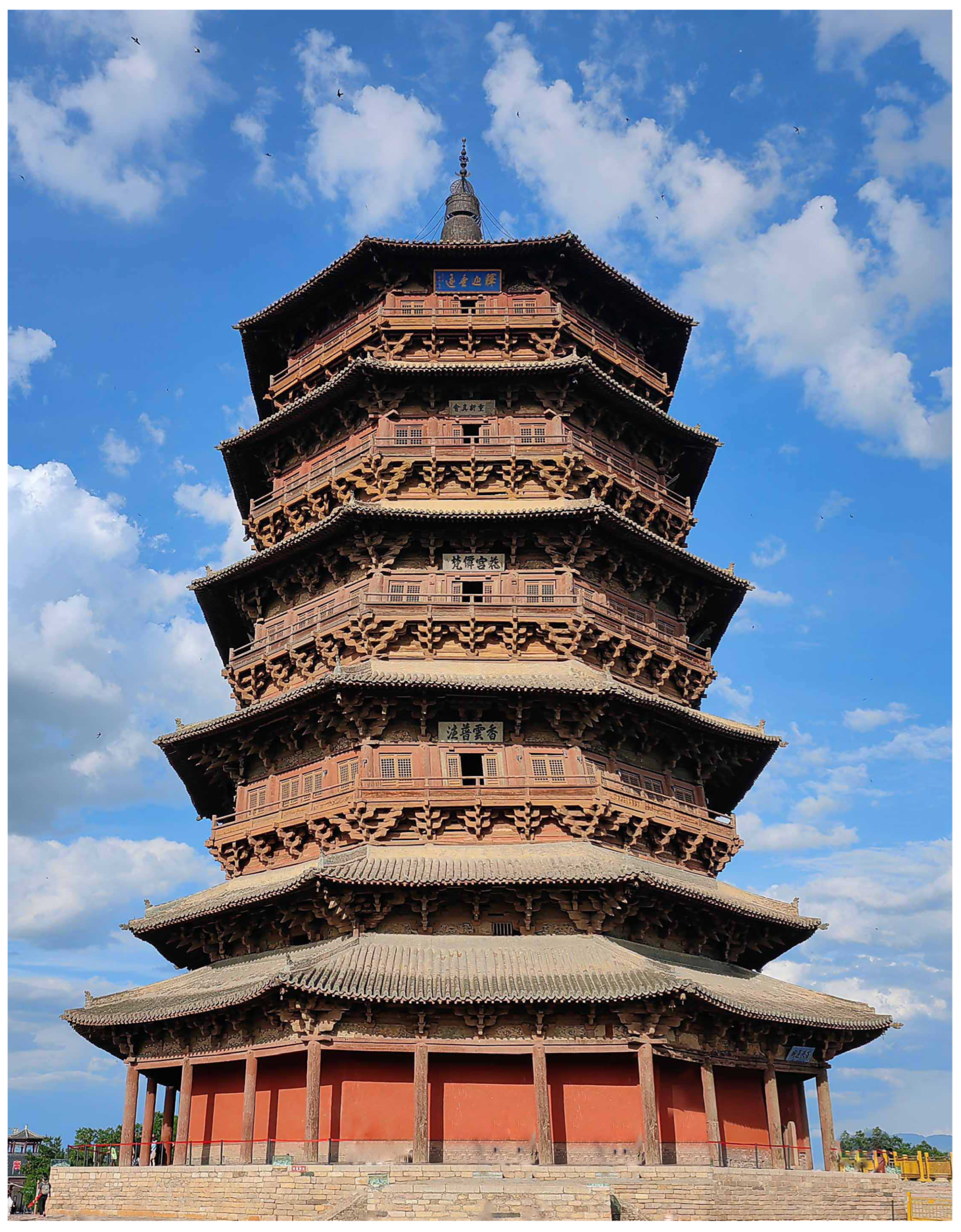
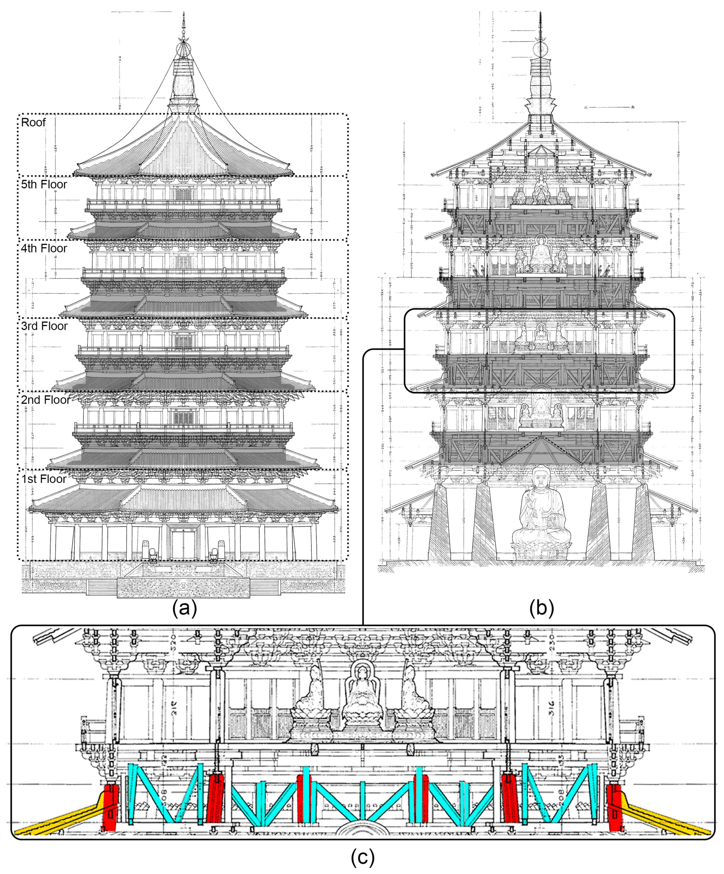
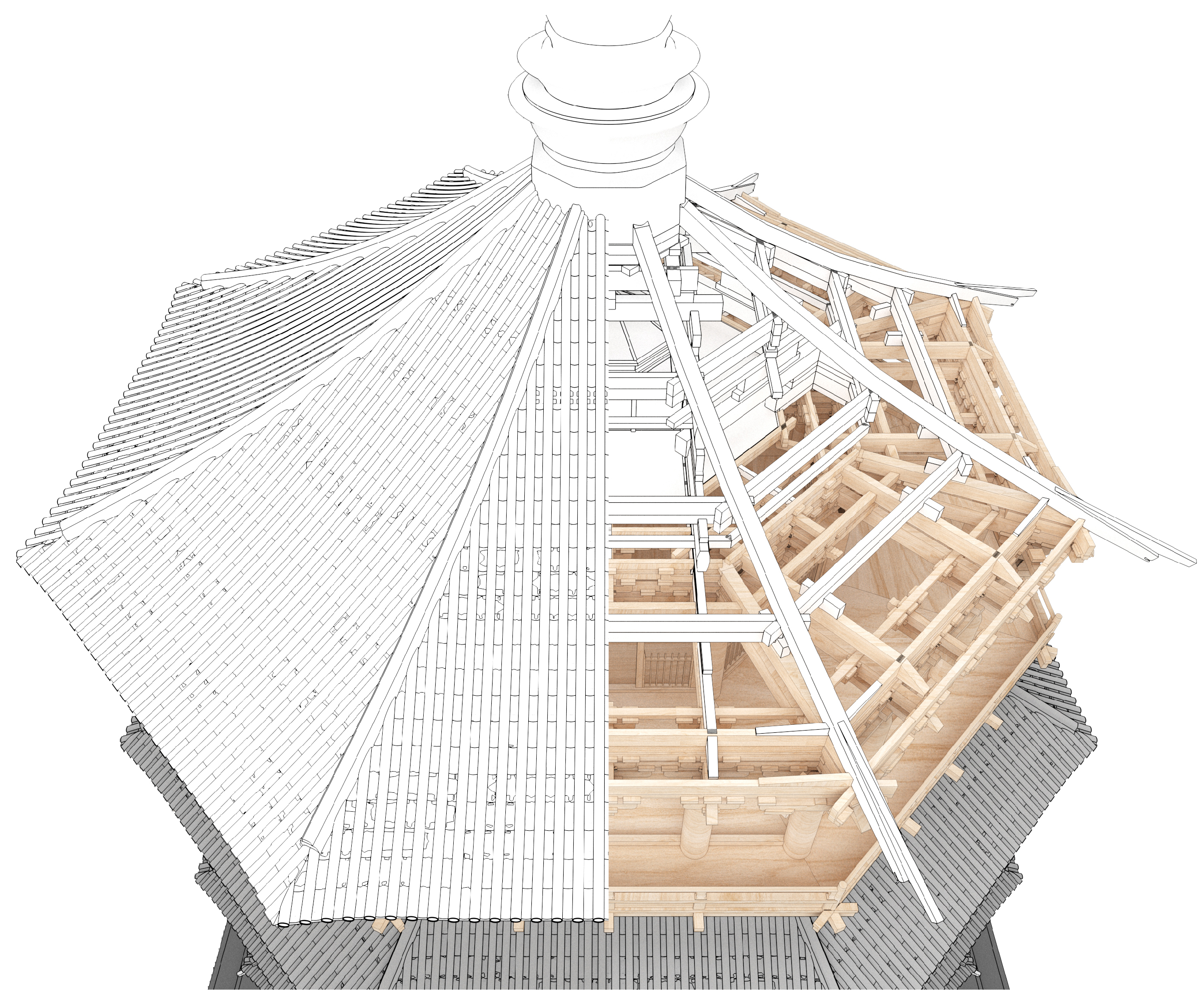
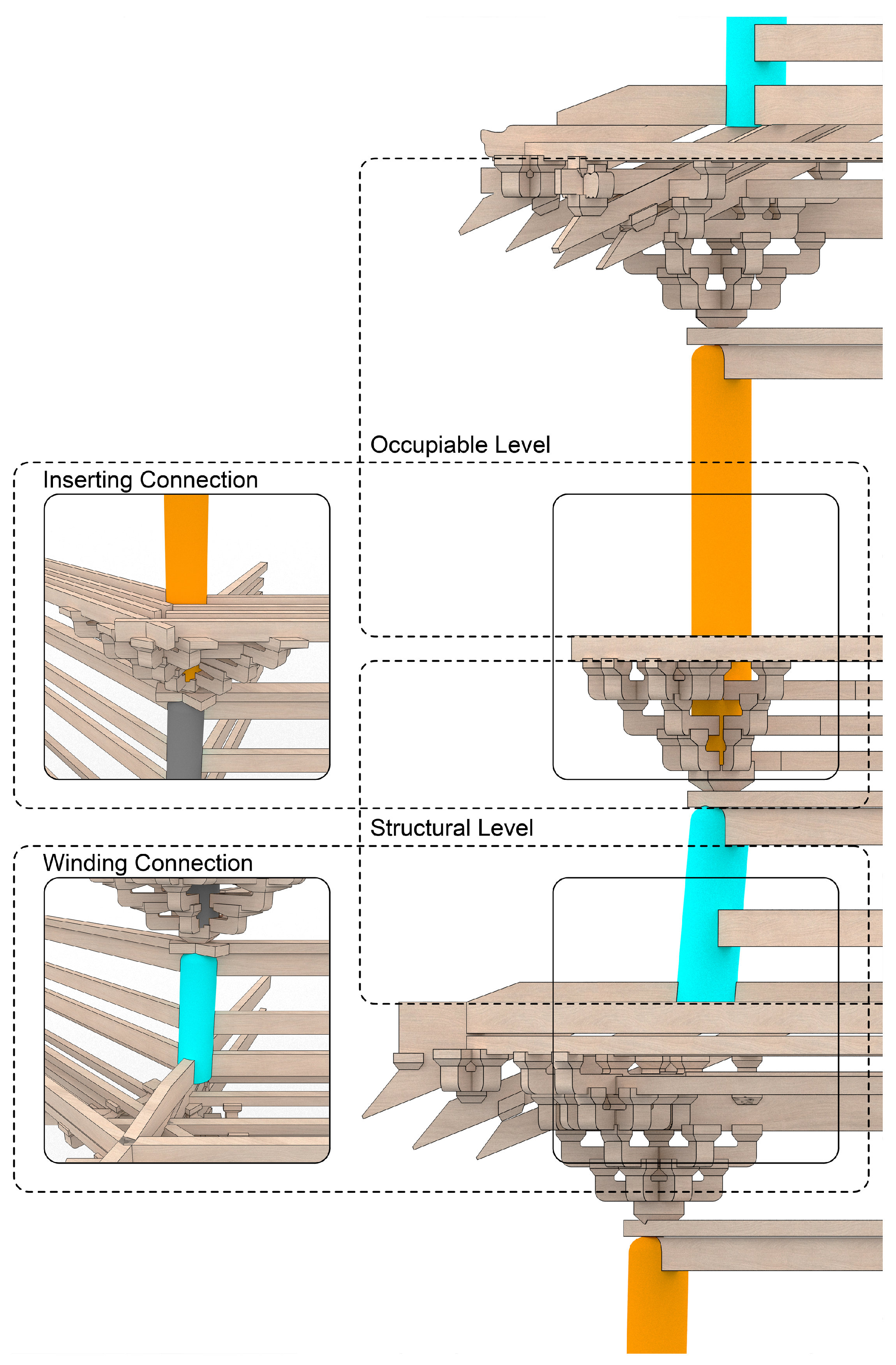
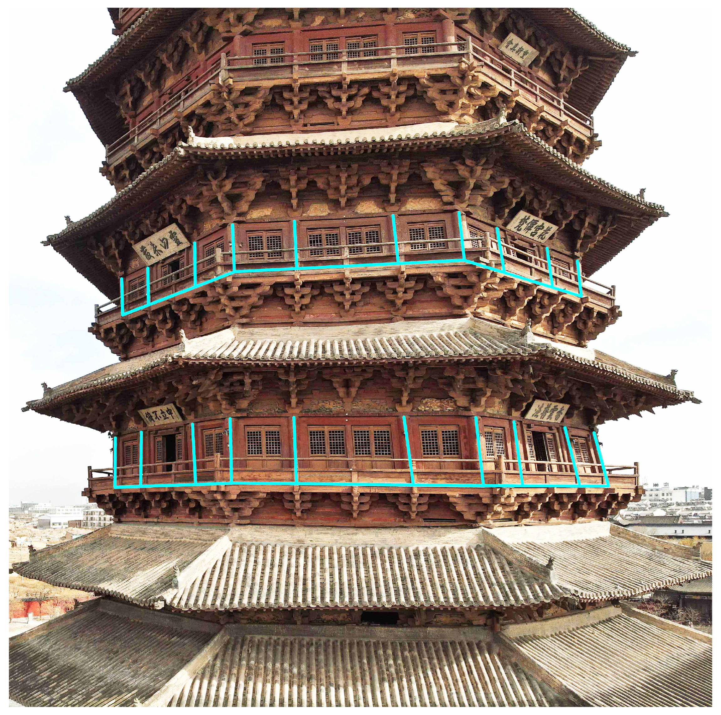
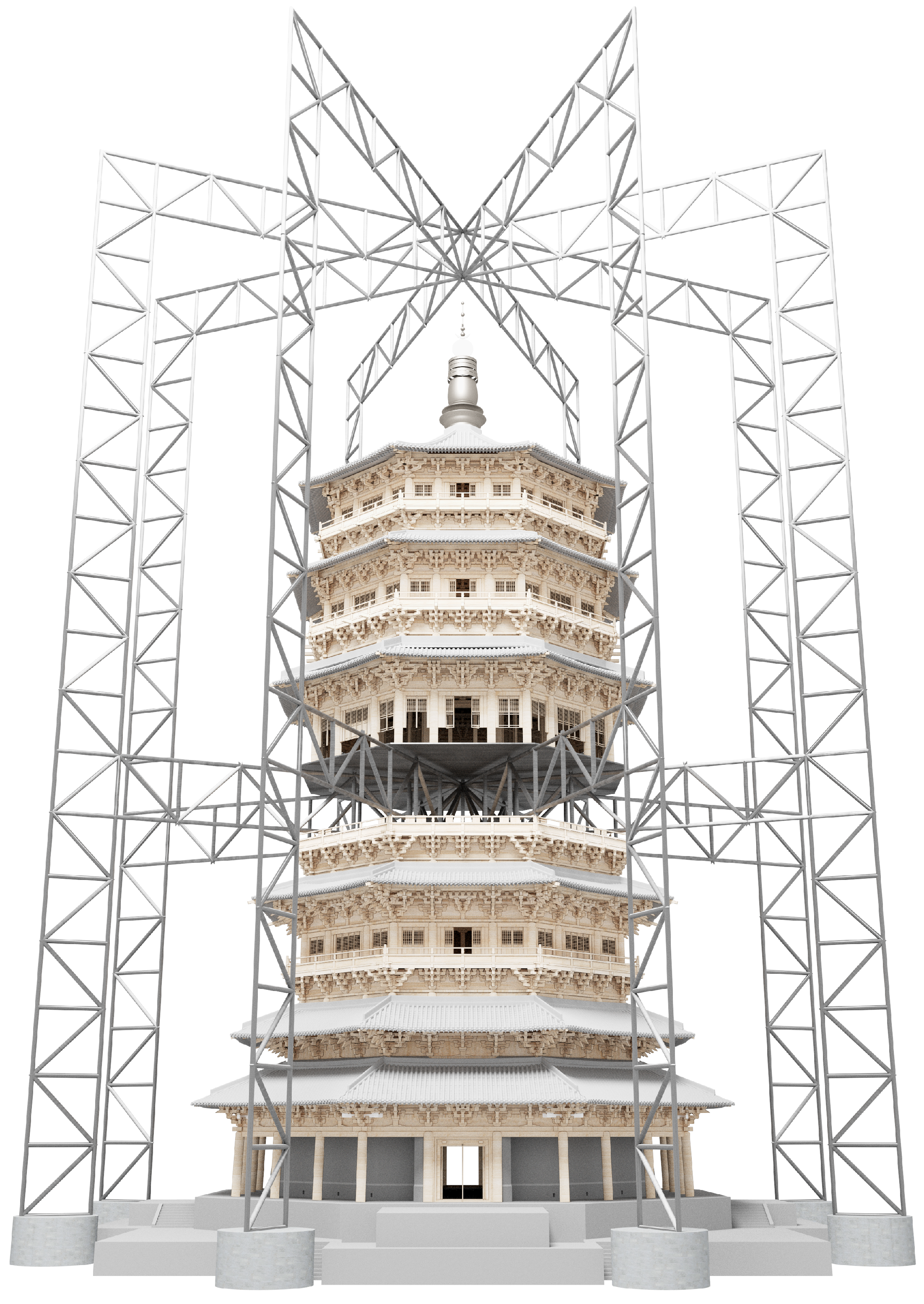
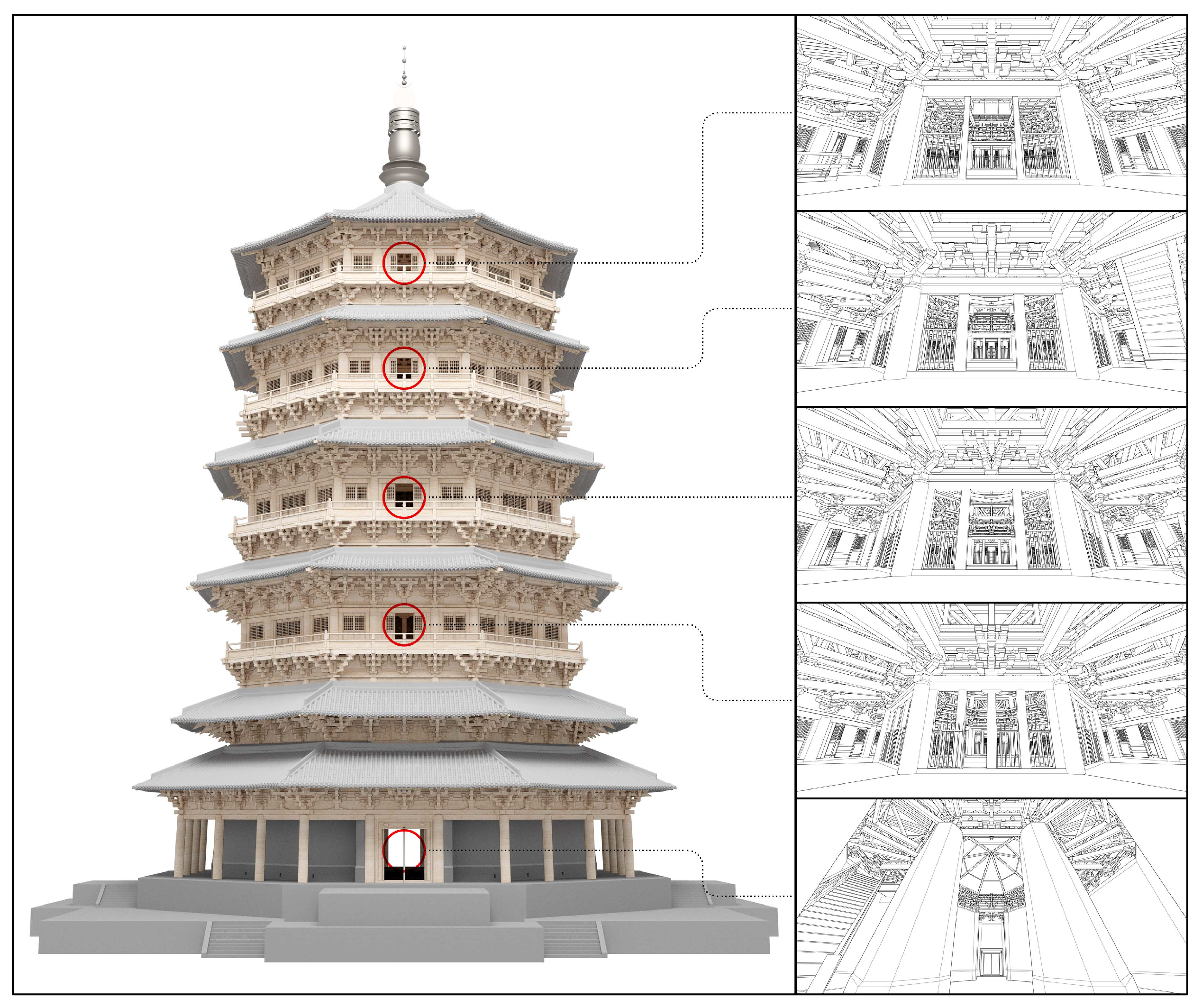
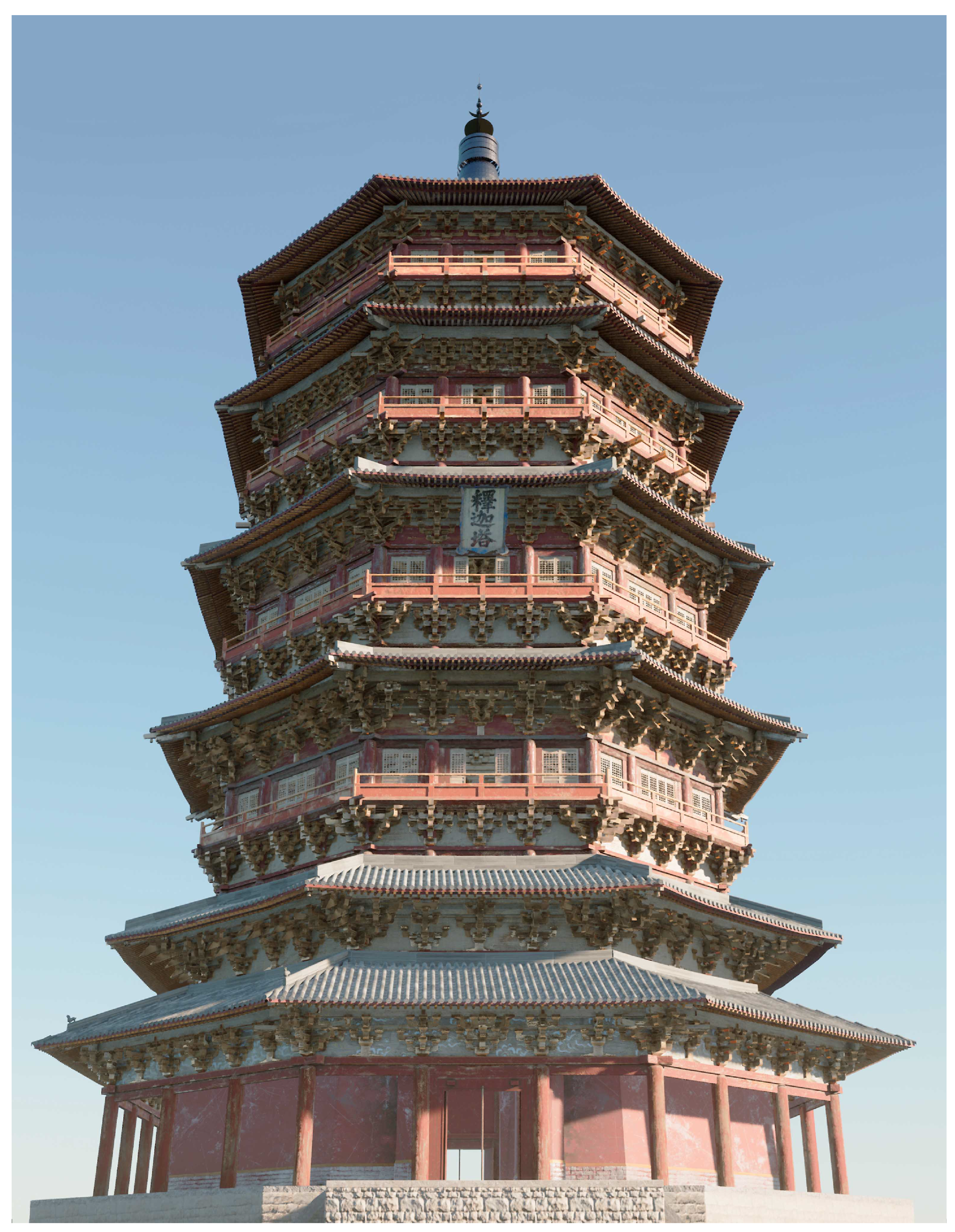
2.1. Structure of the Pagoda
2.2. Current Condition
2.3. Preservation Methods
2.3.1. Total Disassembly and Reassembly
2.3.2. Steel Frame Retrofitting
2.3.3. Lifting Method
2.3.4. Reinforcement of Existing Structure
2.3.5. The Paradox of Decision Making
3. Methodology
3.1. Research Objective and Workflow
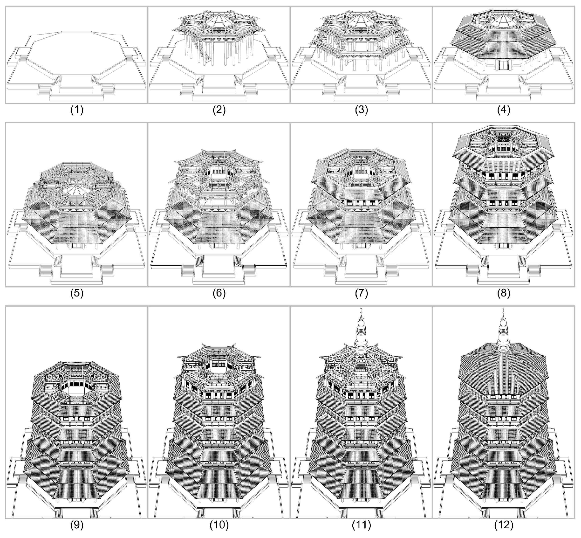
3.2. Modeling Process
3.2.1. Reference Data Collection
3.2.2. Modeling Environment Setup
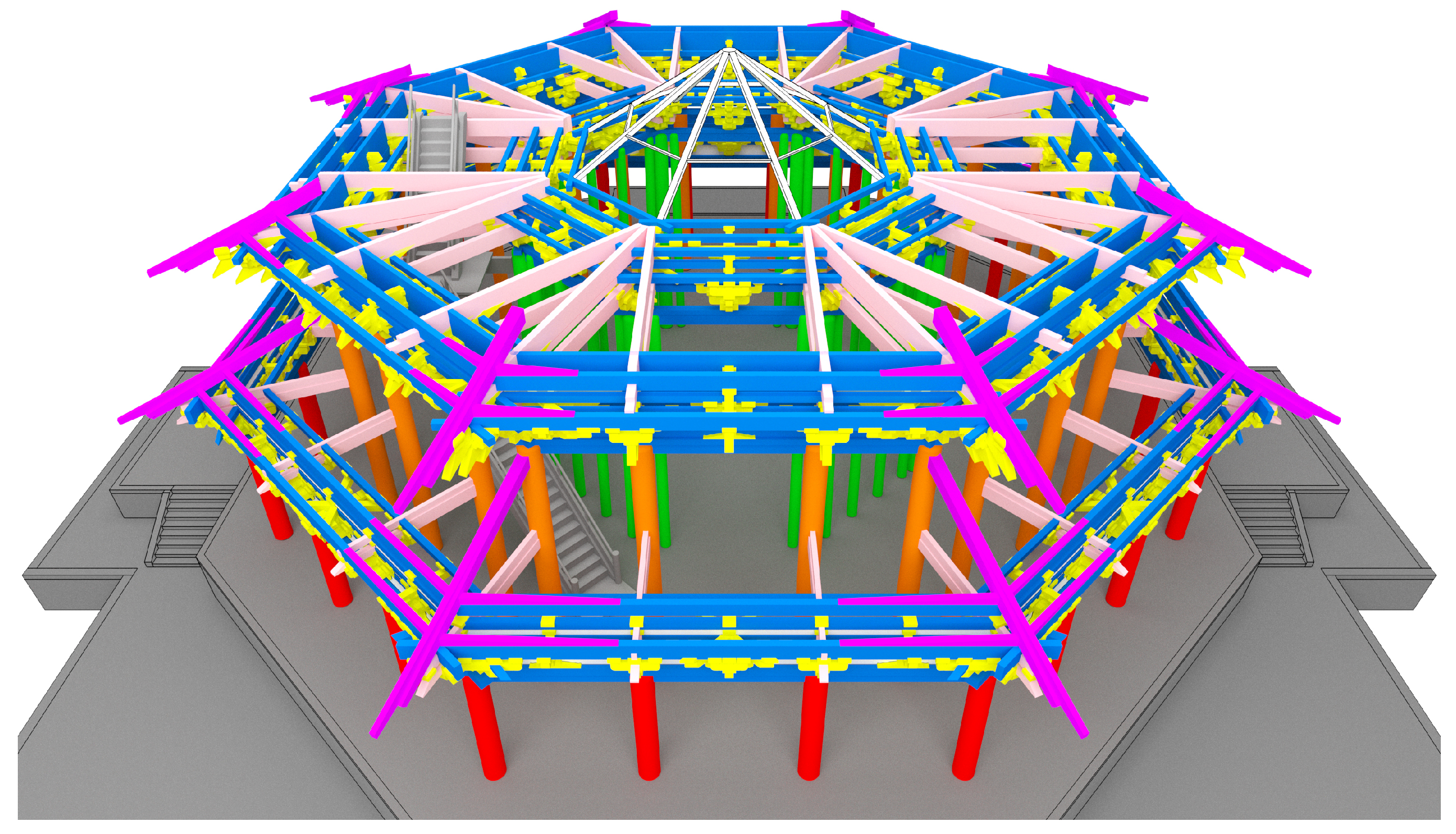
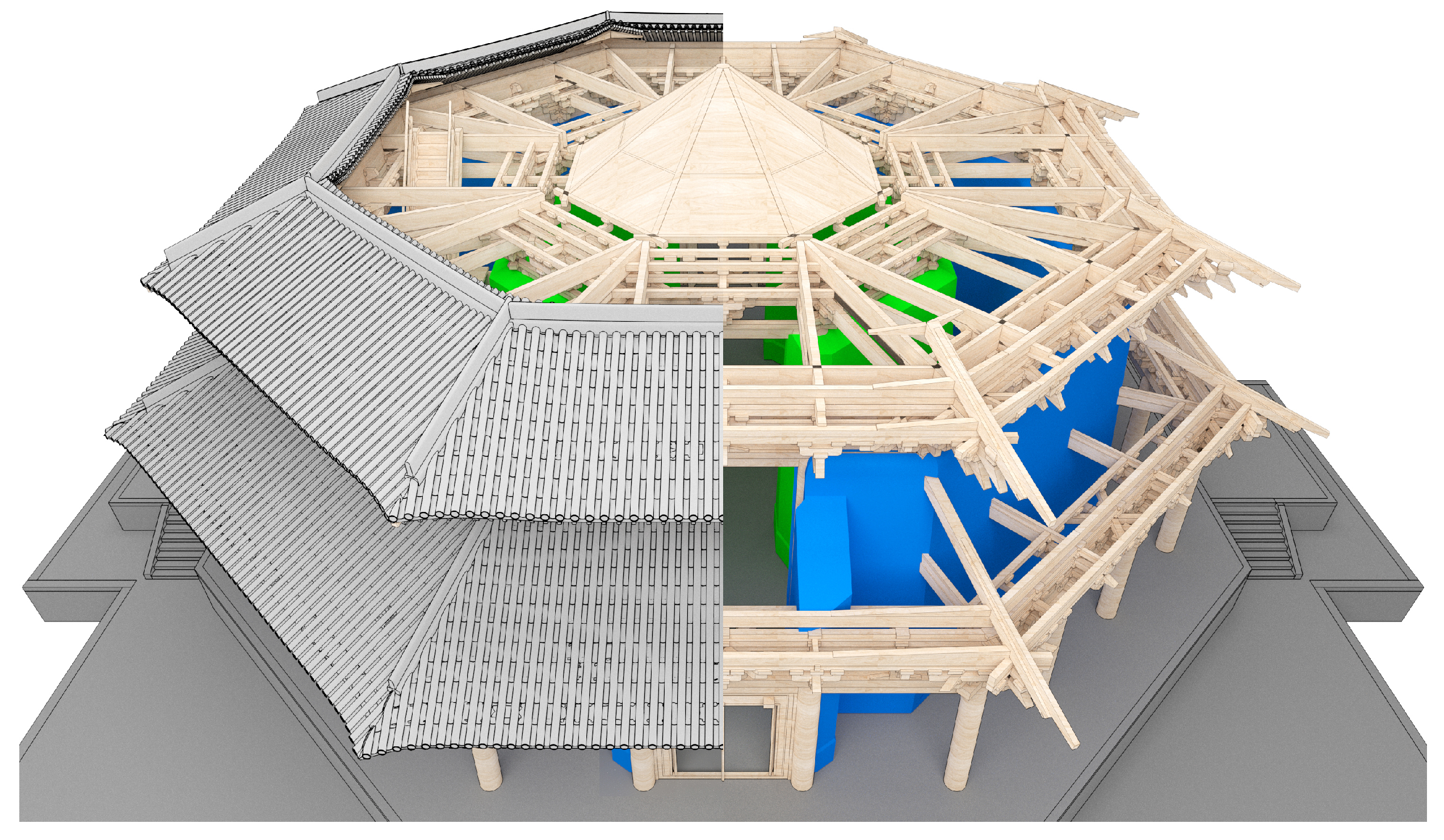
3.2.3. Column Grid Modeling
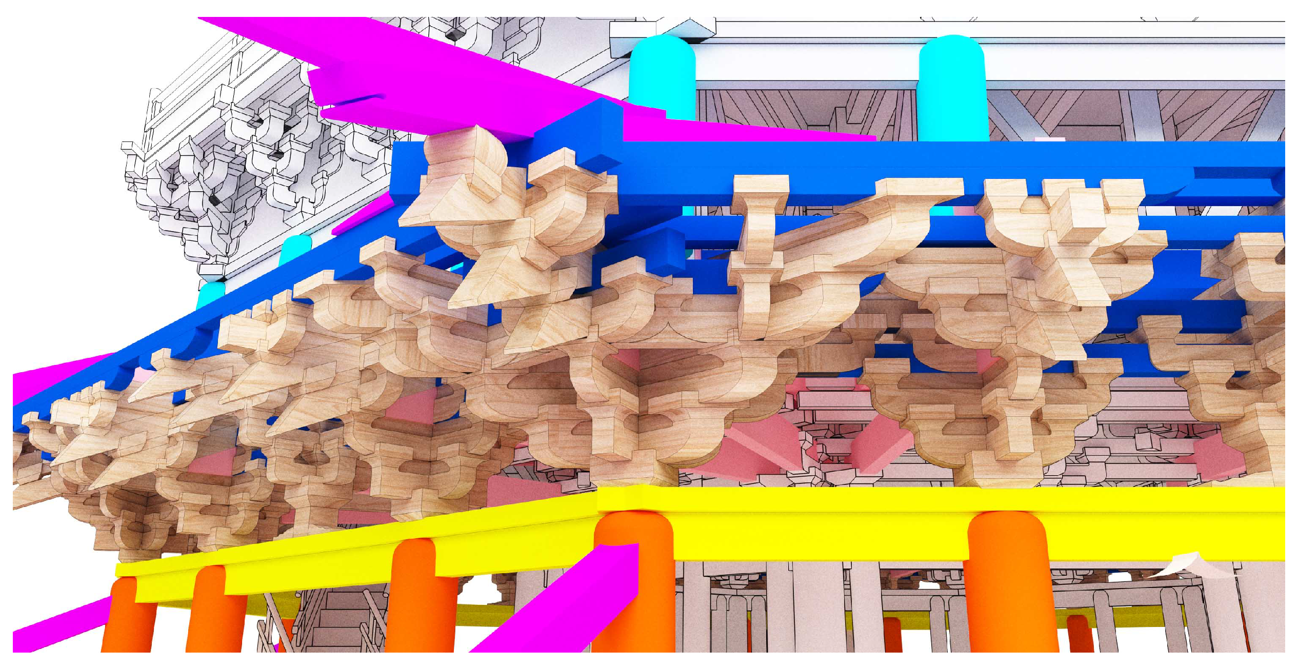
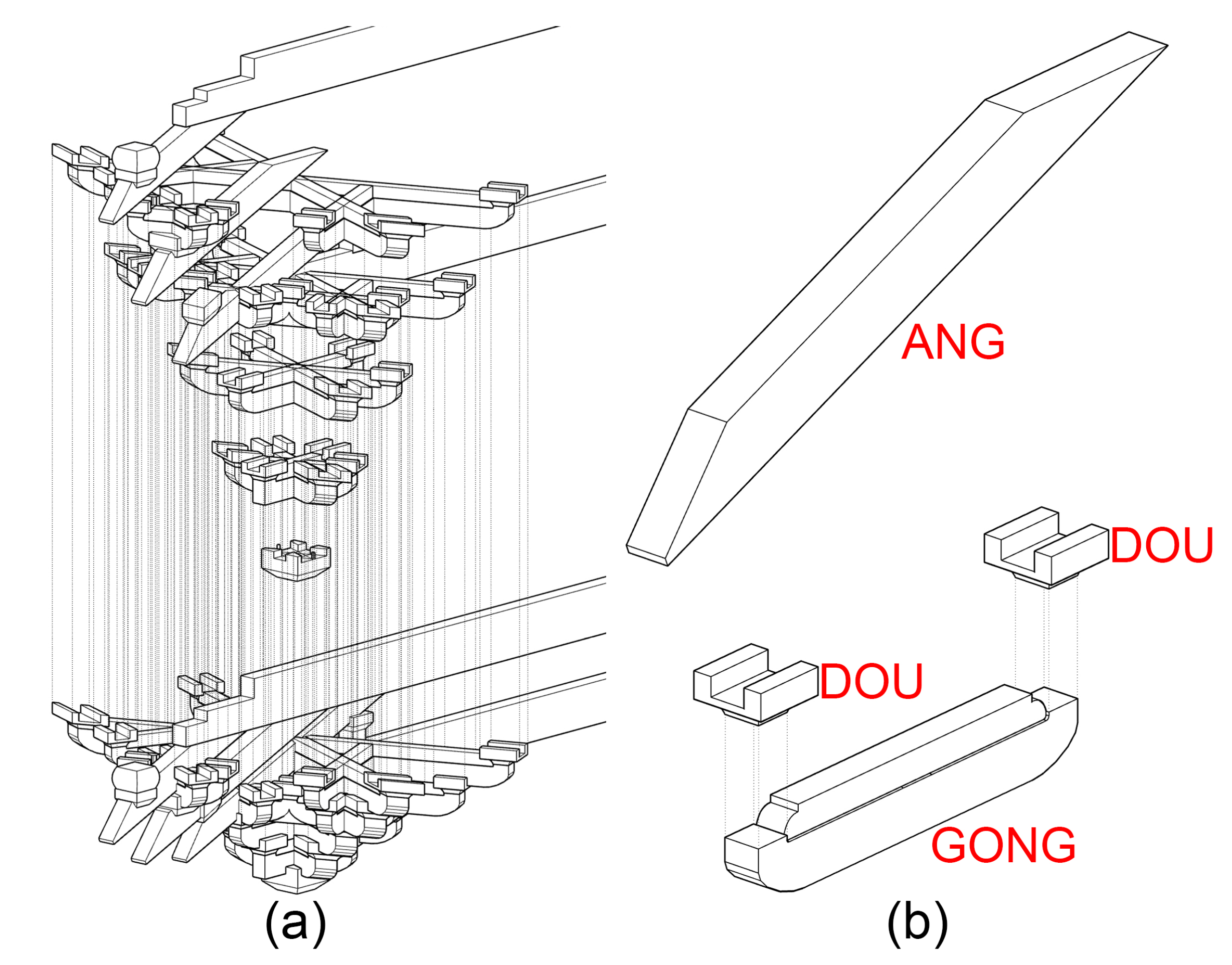
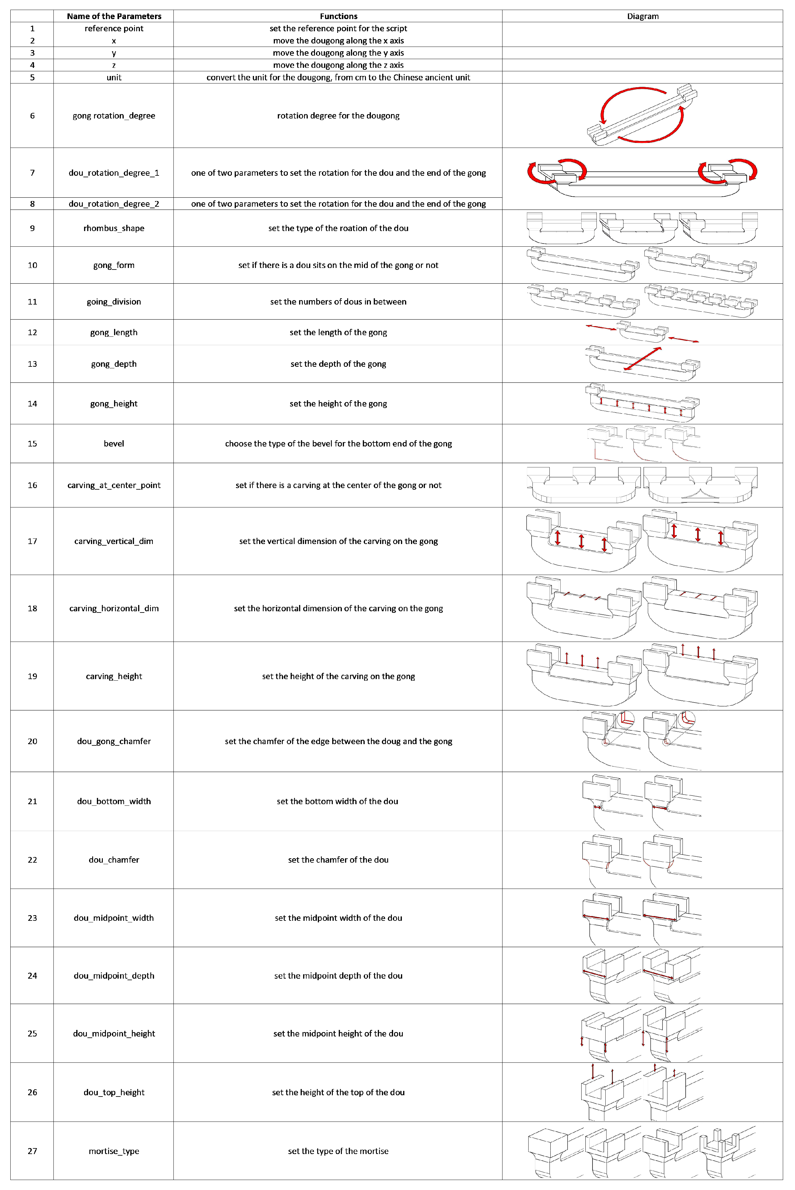
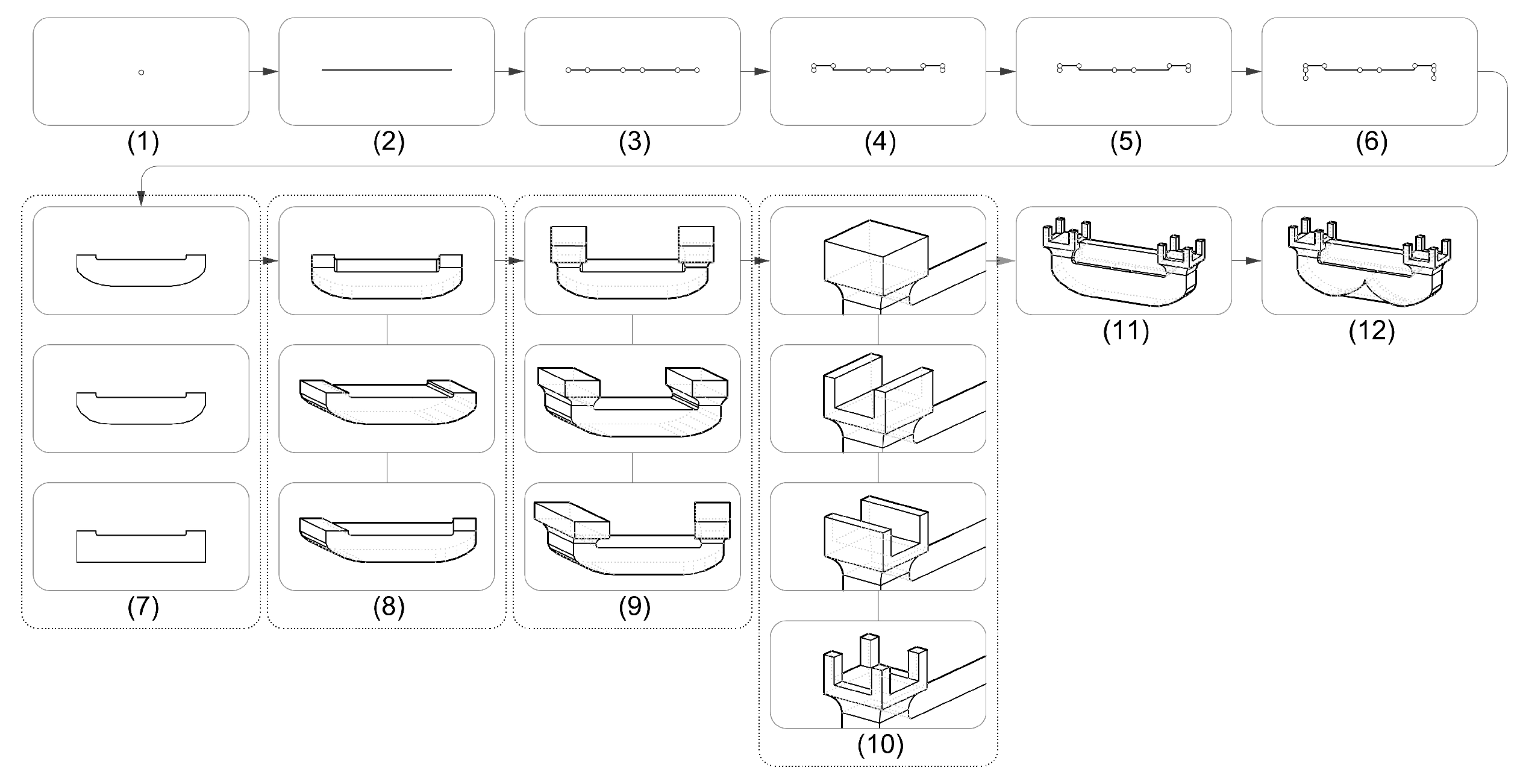
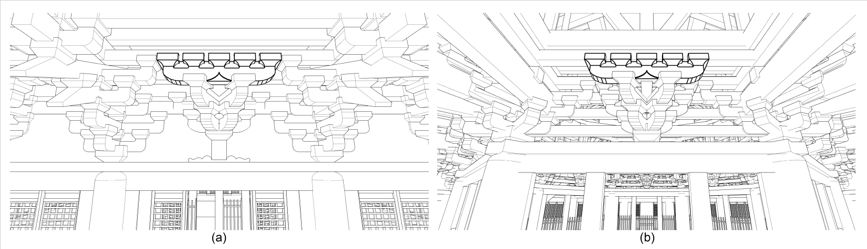
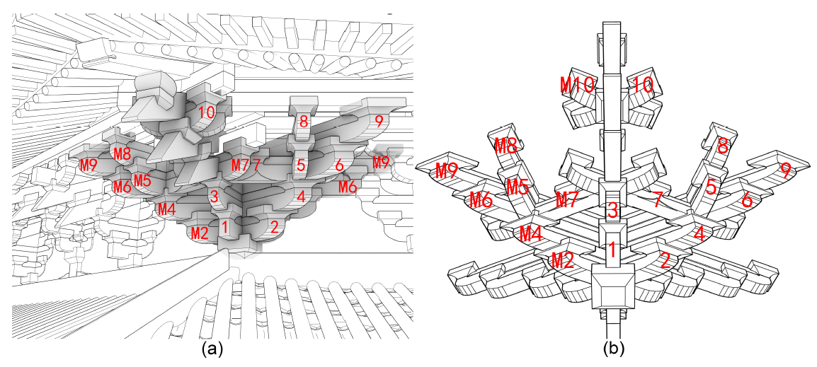
3.2.4. Dougong Modeling
3.2.5. Modeling of Other Structural Members
3.2.6. Modeling of Non-Structural Members
4. Results
5. Discussion
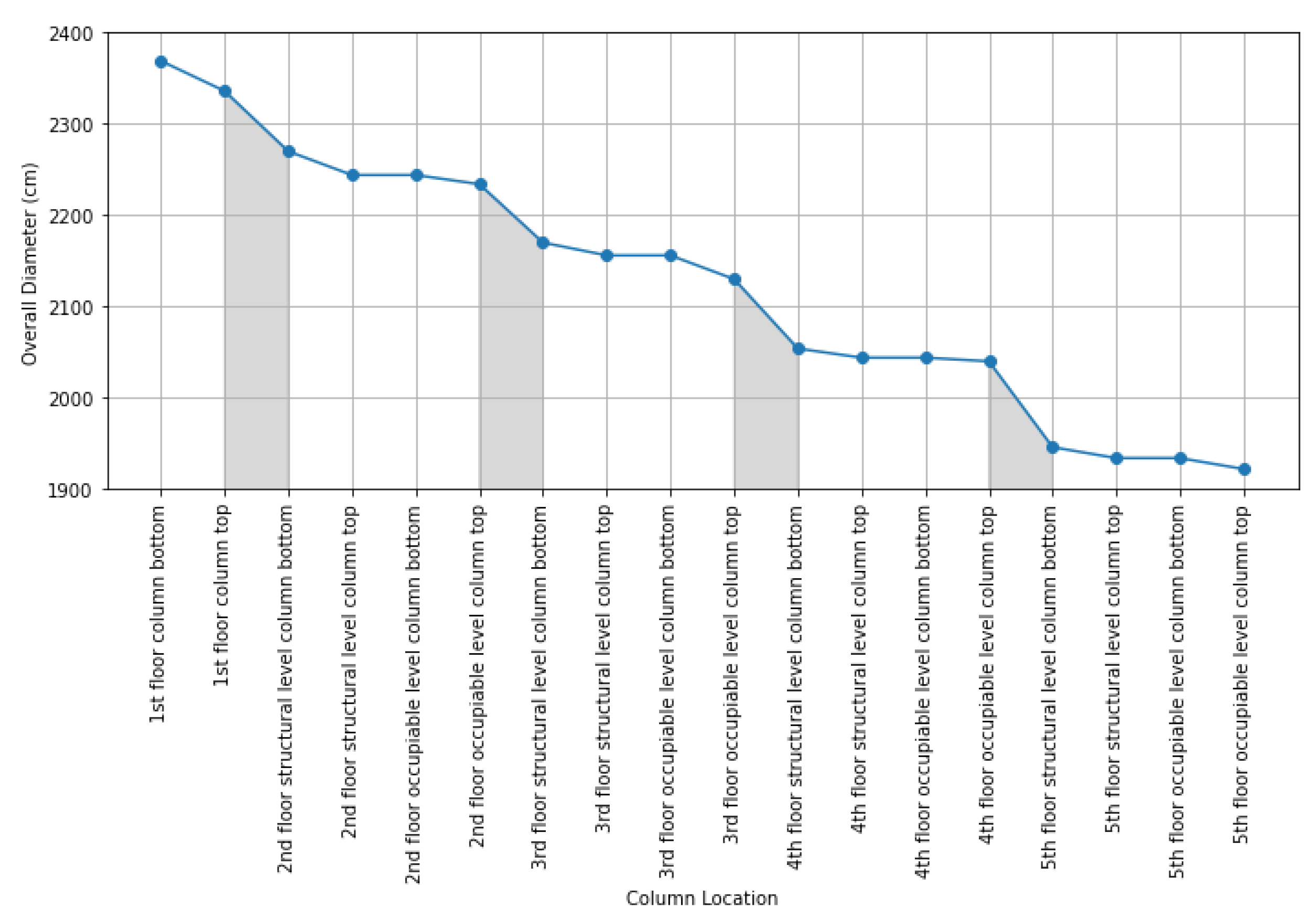
5.1. Tapering Form
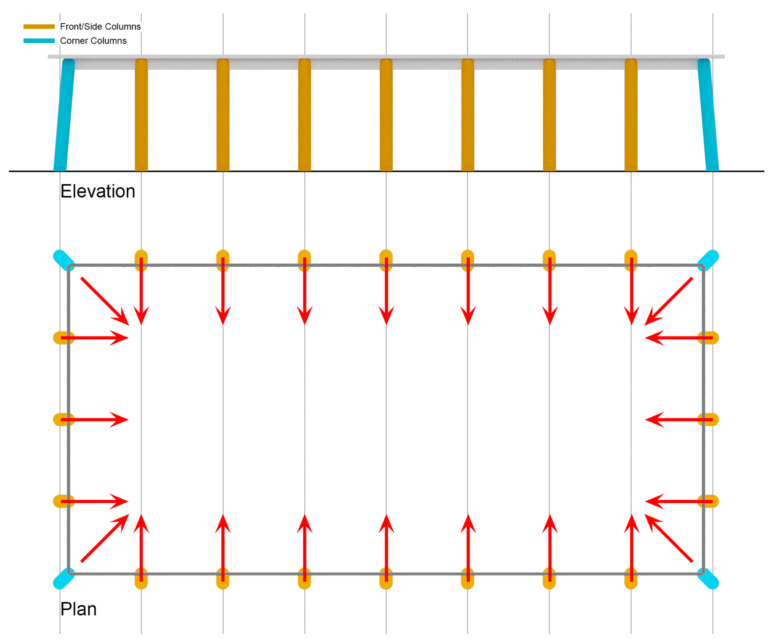
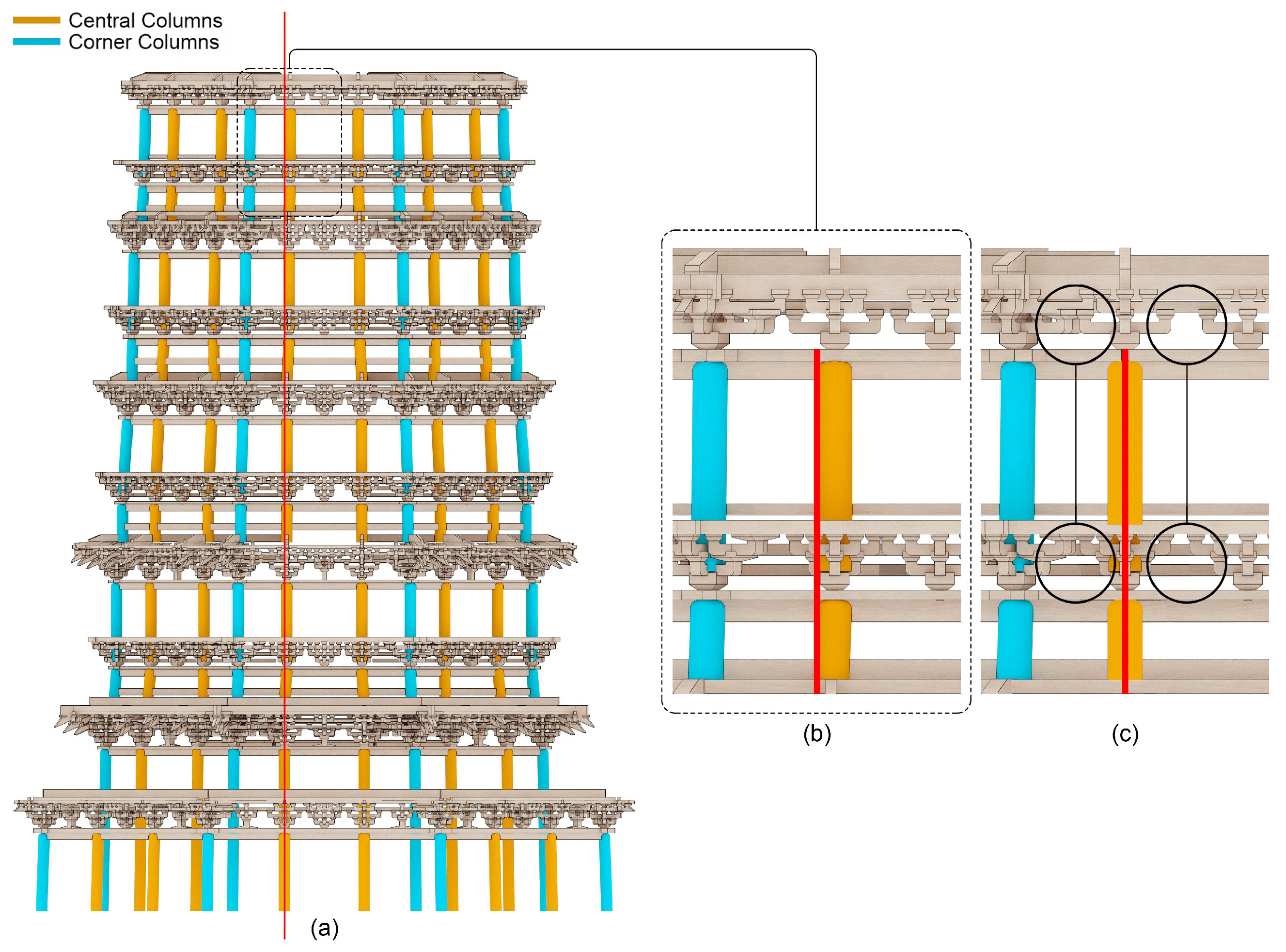
5.2. Leaning Columns
5.3. Contributions to the Existing Literature
5.4. Limitations
6. Conclusions
Author Contributions
Funding
Data Availability Statement
Acknowledgments
Conflicts of Interest
References
- Chen, M. The Yingxian Timber Pagoda, 2nd ed.; Cultural Relics Press: Beijing, China, 1980. [Google Scholar]
- Liu, L. Yingxian Wooden Pagoda. Photograph, 8 June 2024. [Google Scholar]
- Chen, Z.; Zhu, E.; Lam, F.; Pan, J. Structural performance of Dou-Gong brackets of Yingxian Wood Pagoda under vertical load–An experimental study. Eng. Struct. 2014, 80, 274–288. Available online: https://www.sciencedirect.com/science/article/abs/pii/S0141029614005501 (accessed on 1 May 2024). [CrossRef]
- Sha, B.; Xie, L.; Yong, X.; Li, A. An experimental study of the combined hysteretic behavior of dougong and upper frame in Yingxian Wood Pagoda. Constr. Build. Mater. 2021, 305, 124723. Available online: https://www.sciencedirect.com/science/article/pii/S0950061821024788 (accessed on 1 May 2024). [CrossRef]
- Deng, Y.; Li, Y.; Li, A. Seismic safety assessments of historical timber buildings using updated finite element models: Case study of Yingxian wooden pagoda, China. J. Build. Eng. 2023, 63, 105454. Available online: https://www.sciencedirect.com/science/article/pii/S2352710222014607 (accessed on 1 May 2024). [CrossRef]
- Guo, M.; Sun, M.; Pan, D.; Wang, G.; Zhou, Y.; Yan, B.; Fu, Z. High-precision deformation analysis of Yingxian wooden pagoda based on UAV image and terrestrial LiDAR point cloud. Herit. Sci. 2023, 11, 1. [Google Scholar] [CrossRef]
- Lai, D.S.; Leung, A.K.; Chan, D.; Ching, S.H. Cultural heritage preservation using new media methods: Yingxian Wooden Pagoda, China. Virtual Archaeol. Rev. 2019, 10, 103–115. [Google Scholar] [CrossRef]
- Jiang, Y.; Li, A.; Xie, L.; Hou, M.; Qi, Y.; Liu, H. Development and Application of an Intelligent Modeling Method for Ancient Wooden Architecture. ISPRS Int. J. Geo-Inf. 2020, 9, 167. Available online: https://www.mdpi.com/2220-9964/9/3/167 (accessed on 1 May 2024). [CrossRef]
- Yuan, J.; Peng, S.; Shi, Y.; Wang, J. Research on restoration scheme of Ying-Xian Timber Pagoda. In Structural Analysis of Historical Constructions: Anamnesis, Diagnosis, Therapy, Controls; Taylor & Francis Group: London, UK, 2016. [Google Scholar]
- Hou, W.; Wang, L.; Yong, X. Yingxian Wood Tower China Protection Research; Cultural Relics Press: Beijing, China, 2016. [Google Scholar]
- Wang, S. Opinions on the Elevation and Restoration Plan for the Conservation Project of the Yingxian Wooden Pagoda in Shanxi. Tradit. Chin. Archit. Gard. Technol. 2006, 2, 10. [Google Scholar]
- Ma, B. How Should the Yingxian Wooden Pagoda in Shanxi be Repaired? Tradit. Chin. Archit. Gard. Technol. 2006, 2, 3. [Google Scholar]
- Liang, S. Chinese Ancient Buildings Survey Report; Joint Publishing: Beijing, China, 2000. [Google Scholar]
- Moon, K. Comparative Evaluation of Structural Systems for Tapered Tall Buildings. Buildings 2018, 8, 108. [Google Scholar] [CrossRef]
- Li, J. Architecture Methods & Rules, 1st ed.; Chinese Bookstore Press: Beijing, China, 1991. [Google Scholar]


| Column Location | Overall Diameter (cm) | Distance between Corner Columns (cm) | Distance between Central Columns (cm) | Distance between Corner and Central Columns (cm) |
|---|---|---|---|---|
| Buttress level column bottom | 3027 | 1253 | 447 | 403 |
| Buttress level column top | 3000 | 1250 | 444 | 403 |
| 1st floor column bottom | 2369 | 983 | 447 | 268 |
| 1st floor column top | 2336 | 968 | 442 | 263 |
| 2nd floor structural level column bottom | 2270 | 942 | 422 | 260 |
| 2nd floor structural level column top | 2244 | 931 | 421 | 255 |
| 2nd floor occupiable level column bottom | 2244 | 931 | 421 | 255 |
| 2nd floor occupiable level column top | 2234 | 927 | 417 | 255 |
| 3rd floor structural level column bottom | 2170 | 901 | 417 | 242 |
| 3rd floor structural level column top | 2156 | 894 | 384 | 255 |
| 3rd floor occupiable level column bottom | 2156 | 894 | 384 | 255 |
| 3rd floor occupiable level column top | 2130 | 883 | 381 | 251 |
| 4th floor structural level column bottom | 2054 | 850 | 380 | 235 |
| 4th floor structural level column top | 2044 | 847 | 377 | 235 |
| 4th floor occupiable level column bottom | 2044 | 847 | 377 | 235 |
| 4th floor occupiable level column top | 2040 | 842 | 376 | 233 |
| 5th floor structural level column bottom | 1946 | 810 | 370 | 220 |
| 5th floor structural level column top | 1934 | 802 | 368 | 217 |
| 5th floor occupiable level column bottom | 1934 | 802 | 368 | 217 |
| 5th floor occupiable level column top | 1922 | 798 | 364 | 217 |
| Member | Length (cm) | Depth (cm) | Height (cm) |
|---|---|---|---|
| Tuo Feng | 116 | 17 | 15 |
| Zhi Dou | 32/29 | 29/25 | 37 |
| Ni Dao Ling Gong | 116/100 | 17 | 25.5 |
| Gua Zi Gong | 116/104 | 17 | 25.5 |
| Ling Gong | 104/102 | 17 | 25.5 |
| Man Gong | 196/190/186/184 | 17 | 25.5 |
| Ti Mu | 182/104 | 17 | 12/13 |
| Ti Mu on the 5th floor | 96 | 17 | 13 |
| Ling Xing Gong | 94/92 | 17 | 25.5 |
| Shua Tou | 38 | 17 | 25.5 |
| Parameter | Gong 1 | Gong 2 | Gong 3 | Gong 4 | Gong 5 | Gong 6 | Gong 7 | Gong 8 | Gong 9 |
|---|---|---|---|---|---|---|---|---|---|
| Reference Point | −483.115834, −1166.344797, 875.182041 | −483.115834, −1166.344797, 875.182042 | −483.115834, −1166.344797, 875.182043 | −483.115834, −1166.344797, 875.182044 | −483.115834, −1166.344797, 875.182045 | −483.115834, −1166.344797, 875.182046 | −483.115834, −1166.344797, 875.182047 | −483.115834, −1166.344797, 875.182048 | −483.115834, −1166.344797, 875.182049 |
| x | 0 | 0 | 0 | 0 | 0 | 0 | -80.233 | 0 | 0 |
| y | 0 | 0 | 0 | 0 | 80.379 | 0 | 23.787 | 80.379 | 0 |
| z | 23 | 23 | 58.5 | 58.5 | 94 | 94 | 94 | 129.5 | 129.5 |
| Unit | 1.7 | 1.7 | 1.7 | 1.7 | 1.7 | 1.7 | 1.7 | 1.7 | 1.7 |
| Gong Rotation (Degree) | 157.5 | 225 | 157.5 | 225 | 0 | 225 | 90 | 0 | 225 |
| Dou Rotation Degree 1 | 45 | 45 | 45 | 45 | 45 | 45 | 45 | 45 | 45 |
| Dou Rotation Degree 2 | 4 | 4 | 4 | 4 | 4 | 4 | 4 | 4 | 4 |
| Rhombus Shape | 0 | 2 | 0 | 2 | 0 | 2 | 0 | 0 | 2 |
| Gong Form | 0 | 0 | 0 | 0 | 0 | 0 | 0 | 0 | 0 |
| Gong Division | 2 | 2 | 2 | 2 | 2 | 2 | 2 | 2 | 2 |
| Gong Length | 34 | 43 | 56 | 72 | 82 | 113 | 68 | 105 | 145 |
| Gong Depth | 10 | 10 | 10 | 10 | 10 | 10 | 10 | 10 | 10 |
| Gong Height | 15 | 15 | 15 | 15 | 15 | 15 | 15 | 15 | 15 |
| Bevel | None | 5 sides | 5 sides | 5 sides | 5 sides | 5 sides | 5 sides | 5 sides | 5 sides |
| Carving at Center Point | FALSE | FALSE | FALSE | FALSE | FALSE | FALSE | TRUE | FALSE | FALSE |
| Carving Vertical Dim | 1.819 | 1.819 | 1.819 | 1.819 | 1.819 | 1.819 | 1.819 | 1.819 | 1.819 |
| Carving Horizontal Dim | 0.9 | 0.9 | 0.9 | 0.9 | 0.9 | 0.9 | 0.9 | 0.9 | 0.9 |
| Carving Height | 7.7 | 7.7 | 7.7 | 7.7 | 7.7 | 7.7 | 7.7 | 7.7 | 7.7 |
| Dou Gong Chamfer | 1.5 | 1.5 | 1.5 | 1.5 | 1.5 | 1.5 | 1.5 | 1.5 | 1.5 |
| Dou Bottom Width | 10 | 10 | 10 | 10 | 10 | 10 | 10 | 10 | 10 |
| Dou Chamfer | 1.2 | 1.2 | 1.2 | 1.2 | 1.2 | 1.2 | 1.2 | 1.2 | 1.2 |
| Dou Midpoint Width | 20 | 20 | 20 | 20 | 20 | 20 | 20 | 20 | 20 |
| Dou Midpoint Depth | 20 | 20 | 20 | 20 | 20 | 20 | 20 | 20 | 20 |
| Dou Midpoint Height | 2 | 2 | 2 | 2 | 2 | 2 | 2 | 2 | 2 |
| Dou Top Height | 7 | 7 | 7 | 7 | 7 | 7 | 7 | 7 | 7 |
| Mortise Type | Mortise Along Gong’s Direction | Mortise Along Gong’s Direction | Mortise Along Gong’s Direction | Mortise Along Gong’s Direction | Mortise Along Gong’s Direction | Mortise Along Gong’s Direction | Mortise Along Gong’s Direction | Mortise Along Gong’s Direction | Mortise Along Gong’s Direction |
| Column Location | Overall Diameter (cm) | Distance between Central Columns (cm) | Leaning Amount (cm) |
|---|---|---|---|
| Buttress level column bottom | 3027 | 447 | NAN |
| Buttress level column top | 3000 | 444 | −3 |
| 1st floor column bottom | 2369 | 447 | NAN |
| 1st floor column top | 2336 | 442 | −5 |
| 2nd floor structural level column bottom | 2270 | 422 (442) | −20 (0) |
| 2nd floor structural level column top | 2244 | 421 | −1 (−21) |
| 2nd floor occupiable level column bottom | 2244 | 421 | 0 |
| 2nd floor occupiable level column top | 2234 | 417 | −4 |
| 3rd floor structural level column bottom | 2170 | 417 | 0 |
| 3rd floor structural level column top | 2156 | 384 | −33 |
| 3rd floor occupiable level column bottom | 2156 | 384 | 0 |
| 3rd floor occupiable level column top | 2130 | 381 | −3 |
| 4th floor structural level column bottom | 2054 | 380 | −1 |
| 4th floor structural level column top | 2044 | 377 | −3 |
| 4th floor occupiable level column bottom | 2044 | 377 | 0 |
| 4th floor occupiable level column top | 2040 | 376 | −1 |
| 5th floor structural level column bottom | 1946 | 370 | −6 |
| 5th floor structural level column top | 1934 | 368 | −2 |
| 5th floor occupiable level column bottom | 1934 | 368 | 0 |
| 5th floor occupiable level column top | 1922 | 364 | −4 |
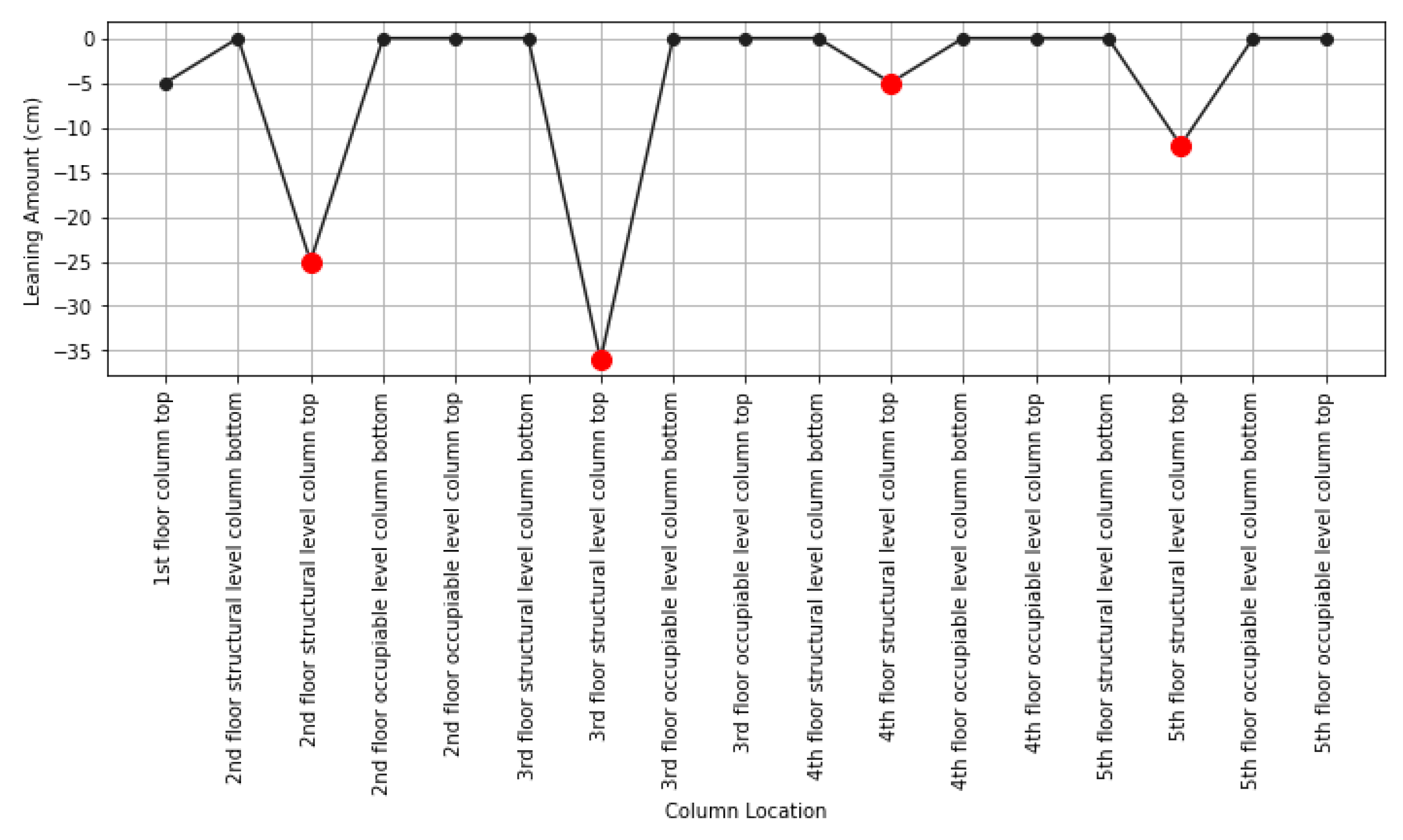
| Column Location | Overall Diameter (cm) | Distance between Central Columns (cm) | Leaning Amount (cm) |
|---|---|---|---|
| Buttress level column bottom | 3027 | 447 | NAN |
| Buttress level column top | 3000 | 444 | −3 |
| 1st floor column bottom | 2369 | 447 | NAN |
| 1st floor column top | 2336 | 442 | −5 |
| 2nd floor structural level column bottom | 2270 | 442 | 0 |
| 2nd floor structural level column top | 2244 | 417 | −25 |
| 2nd floor occupiable level column bottom | 2244 | 417 | 0 |
| 2nd floor occupiable level column top | 2234 | 417 | 0 |
| 3rd floor structural level column bottom | 2170 | 417 | 0 |
| 3rd floor structural level column top | 2156 | 381 | −36 |
| 3rd floor occupiable level column bottom | 2156 | 381 | 0 |
| 3rd floor occupiable level column top | 2130 | 381 | 0 |
| 4th floor structural level column bottom | 2054 | 381 | 0 |
| 4th floor structural level column top | 2044 | 376 | −5 |
| 4th floor occupiable level column bottom | 2044 | 376 | 0 |
| 4th floor occupiable level column top | 2040 | 376 | 0 |
| 5th floor structural level column bottom | 1946 | 376 | 0 |
| 5th floor structural level column top | 1934 | 364 | −12 |
| 5th floor occupiable level column bottom | 1934 | 364 | 0 |
| 5th floor occupiable level column top | 1922 | 364 | 0 |
Disclaimer/Publisher’s Note: The statements, opinions and data contained in all publications are solely those of the individual author(s) and contributor(s) and not of MDPI and/or the editor(s). MDPI and/or the editor(s) disclaim responsibility for any injury to people or property resulting from any ideas, methods, instructions or products referred to in the content. |
© 2024 by the authors. Licensee MDPI, Basel, Switzerland. This article is an open access article distributed under the terms and conditions of the Creative Commons Attribution (CC BY) license (https://creativecommons.org/licenses/by/4.0/).
Share and Cite
Wang, D.; Li, S.Y.; Liu, R.; Hu, J.; Wang, A. Parametric Modeling and Column Grid Analysis of the Sakyamuni Pagoda at Fogong Temple: Insights into the Yingxian Wooden Pagoda. Buildings 2024, 14, 2464. https://doi.org/10.3390/buildings14082464
Wang D, Li SY, Liu R, Hu J, Wang A. Parametric Modeling and Column Grid Analysis of the Sakyamuni Pagoda at Fogong Temple: Insights into the Yingxian Wooden Pagoda. Buildings. 2024; 14(8):2464. https://doi.org/10.3390/buildings14082464
Chicago/Turabian StyleWang, Daoru, Stephanie Yanqiu Li, Ruguan Liu, Jianxin Hu, and Ang Wang. 2024. "Parametric Modeling and Column Grid Analysis of the Sakyamuni Pagoda at Fogong Temple: Insights into the Yingxian Wooden Pagoda" Buildings 14, no. 8: 2464. https://doi.org/10.3390/buildings14082464
APA StyleWang, D., Li, S. Y., Liu, R., Hu, J., & Wang, A. (2024). Parametric Modeling and Column Grid Analysis of the Sakyamuni Pagoda at Fogong Temple: Insights into the Yingxian Wooden Pagoda. Buildings, 14(8), 2464. https://doi.org/10.3390/buildings14082464