Article

Bearing Capacity of Hybrid (Steel and GFRP) Reinforced Columns under Eccentric Loading: Theory and Experiment

1
School of Civil Engineering, Chang’an University, Xi’an 710061, China
2
Engineering Research Institute, China Construction Eighth Engineering Division, Shanghai 200122, China
3
School of Civil and Transportation Engineering, Guangdong University of Technology, Guangzhou 510006, China
4
Department of Structural Engineering, Tongji University, Shanghai 200092, China
*
Authors to whom correspondence should be addressed.
Buildings 2024, 14(8), 2472; https://doi.org/10.3390/buildings14082472
Submission received: 29 May 2024 / Revised: 1 August 2024 / Accepted: 5 August 2024 / Published: 10 August 2024
(This article belongs to the Special Issue Low-Carbon and Green Materials in Construction—2nd Edition)

Abstract

:
In order to reveal the mechanical behavior of short concrete columns reinforced with hybrid steel and glass FRP bars, 10 specimens were designed for eccentric compression tests. The effect of eccentricity and load–displacement/strain of the specimens was studied. Test results indicate that the damage process and failure mode of these hybrid RC columns was similar to those in the conventional steel-reinforced concrete columns. The mode of failure for all specimens is characterized as large eccentricity compression failure, and the ultimate bearing capacity of the columns decreases with the increase in eccentricity. However, the impact of the varying axial stiffness ratio between GFRP and steel bars on the bearing capacity can be considered negligible. In addition, based on theoretical analysis, two boundary states for distinguishing failure mode and the formulae for calculating ultimate bearing capacity in different failure modes of eccentrically loaded hybrid RC columns are proposed. The computed results agree well with test results.

1. Introduction

Based on its advantages, such as high strength, low cost, easily accessible materials, simplicity in construction and molding, as well as durability, concrete has emerged as the most prevalent building material in foundation construction [1,2,3]. Corrosion of reinforcing steel embedded in concrete causes most deterioration of concrete structures [4,5,6]. Fiber-reinforced polymer (FRP) bars have emerged as a possible solution for eliminating corrosion problems in concrete owing to their better corrosion resistance, non-conductivity, strength-to-weight ratio, and fatigue resistance [7,8,9,10]. In general, FRP bars, composed of different fibers (carbon, glass, or basalt) and resin matrix (polyesters, vinyl esters, or epoxies), have exhibited similar linear elasticity under load. Carbon FRP (CFRP) bars are still far too expensive for most applications, and basalt FRP (BFRP) bars have recently been garnering attention as replacement for other FRP bars. During the last few decades, civil engineers and researchers have paid more attention to glass FRP (GFRP) bars on account of the lower cost and easy production compared with other FRP bars. However, GFRP bars are very sensitive to the alkaline environment within concrete due to the poor alkali resistance of fibers [11]. A number of concrete structures reinforced with GFRP bars have already come into service [12]. However, due to the linear elastic characteristics of FRP bars under load, concrete elements reinforced with pure FRP reinforcement exhibit brittle failure without warning. Design codes for concrete structures reinforced with FRP bars encourage an over-reinforced design since it may lead to a less catastrophic failure with a higher degree of deformability. Moreover, because of FRP’s low elastic modulus, FRP-reinforced concrete (FRP-RC) members exhibit larger deflections and wider cracks than steel-reinforced concrete (SRC) beams having the same cross-section and reinforcement area. Consequently, FRP-RC design is generally controlled by serviceability limit states [13,14].
To address these problems, a hybrid combination of FRP and steel reinforcement, which simultaneously exploits the benefits of the two materials, has been proposed [15,16]. By placing corrosion-resistant FRP bars near the outer surface and the ductile steel bars at the inner levels of the tension zone, the durability can be improved compared with SRC elements, and the ductility and serviceability can be improved compared with FRP-RC elements [14]. The behavior of hybrid sections has been studied by many researchers [17,18,19,20,21], and the feasibility was experimentally confirmed. However, limited experimental data and theoretical studies on the structural performance of hybrid RC columns are available in the literature.
The mechanical and physical properties of FRP bars are considerably different from those of steel rebars, which result in dissimilarity of hybrid RC elements’ mechanical behavior compared to those of FRP-RC columns [22,23,24,25,26,27,28,29,30,31,32,33] and the design of the hybrid section for columns will be more complex. Choo [28] studied the bearing capacity–bending moment (Nu–Mu) curve relationship of concrete columns with different FRP bars, and the results showed that there is no boundary point between large and small eccentricities in the curve of the bearing capacity of FRP-RC columns, and there is no equilibrium failure. The fracture mode of the FRP bars occurs only when the reinforcement ratio is low [29]. Zadeh [30] analyzed the second-order effect of an FRP–RC frame and showed that when the reinforcement ratio is the same, the effective bending stiffness values of a GFRP-RC column and a CFRP-RC column are 60% and 80% of that of the SRC column, respectively. Xue [31] studied eccentrically loaded FRP–RC columns, modified the calculation formula of the moment amplification factor of eccentrically compressed FRP–RC columns by regressing the simulation results, and proposed a bearing capacity calculation formula for eccentrically loaded FRP–RC columns. Ibrahim [33] investigated the seismic performance of hybrid RC bridge columns, and the results verify that the hybrid structural system ensured the existence of a stable post-yield stiffness, which means after steel yielding, the FRP bars can continue to carry loading when the section is well designed. When designing a hybrid section, there are at least two different ways, namely under the same reinforcement area or under the same axial stiffness of reinforcement. The differences between above design methods are discussed sufficiently in reference [16] and the latter method was proposed.
In this paper, we investigated the bearing capacity of hybrid RC columns both theoretically and experimentally. We designed and tested large eccentric compression failure mode hybrid RC columns with different concrete strength, different eccentricity, and reinforcement ratios and with different ratios of the axial stiffness of GFRP and that of steel reinforcement (Rf) [15]. The boundary states of eccentrically loaded hybrid RC columns were set, which are helpful to predict different component failure modes. And calculation formulae for the bearing capacity of the eccentrically loaded hybrid RC columns were derived on the basis of the internal force balance condition and deformation compatibility condition. Finally, we compared the experimental results with the theoretical predictions to verify the validity.

2. Experimental Program
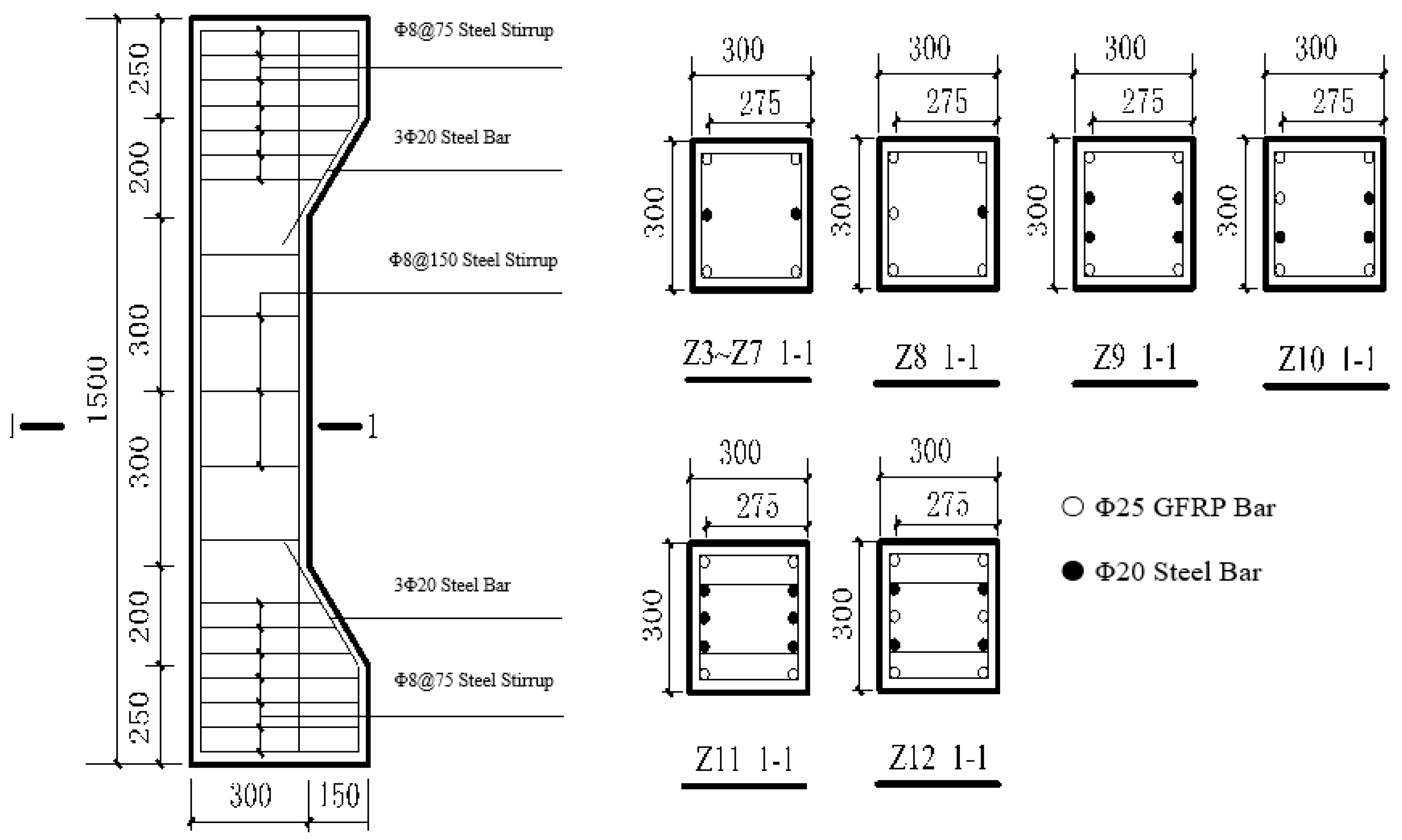
2.1. Test Specimens

Ten short columns were designed for eccentric compression tests. The slenderness ratio λ = L/b = 5, where L = 1500 mm, and the section size is b × h = 300 mm × 300 mm. The eccentrically loaded columns were designed with corbels, and three rows of steel meshes were set at each end, with a spacing of 50 mm to prevent local bearing failure. Table 1 lists the structural parameters. Figure 1 shows the details of section reinforcement.

2.2. Materials

The average concrete strength under compression was 46.2 MPa and 27.3 MPa as evaluated by tests on six 150 mm × 150 mm × 150 mm cube specimens. The longitudinal reinforcement was in the form of Φ12 HRB335 steel bars, and the stirrup was in the form of Φ8 HPB235 steel bars. Table 2 lists the steel bar parameters. Table 3 lists the tensile performance test results of Φ25 GFRP bars. Table 4 lists the compressive performance test results of the GFRP bars.

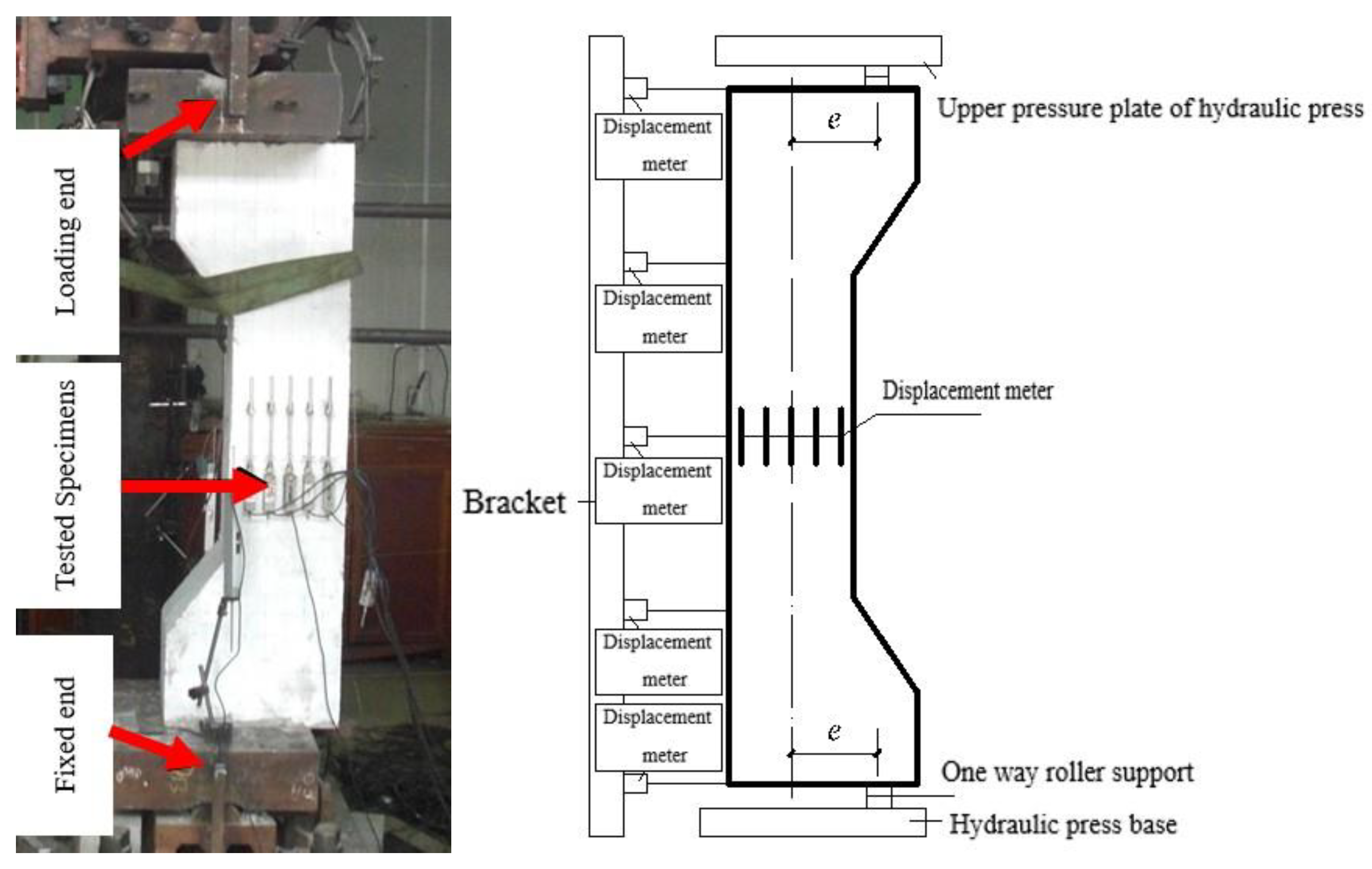
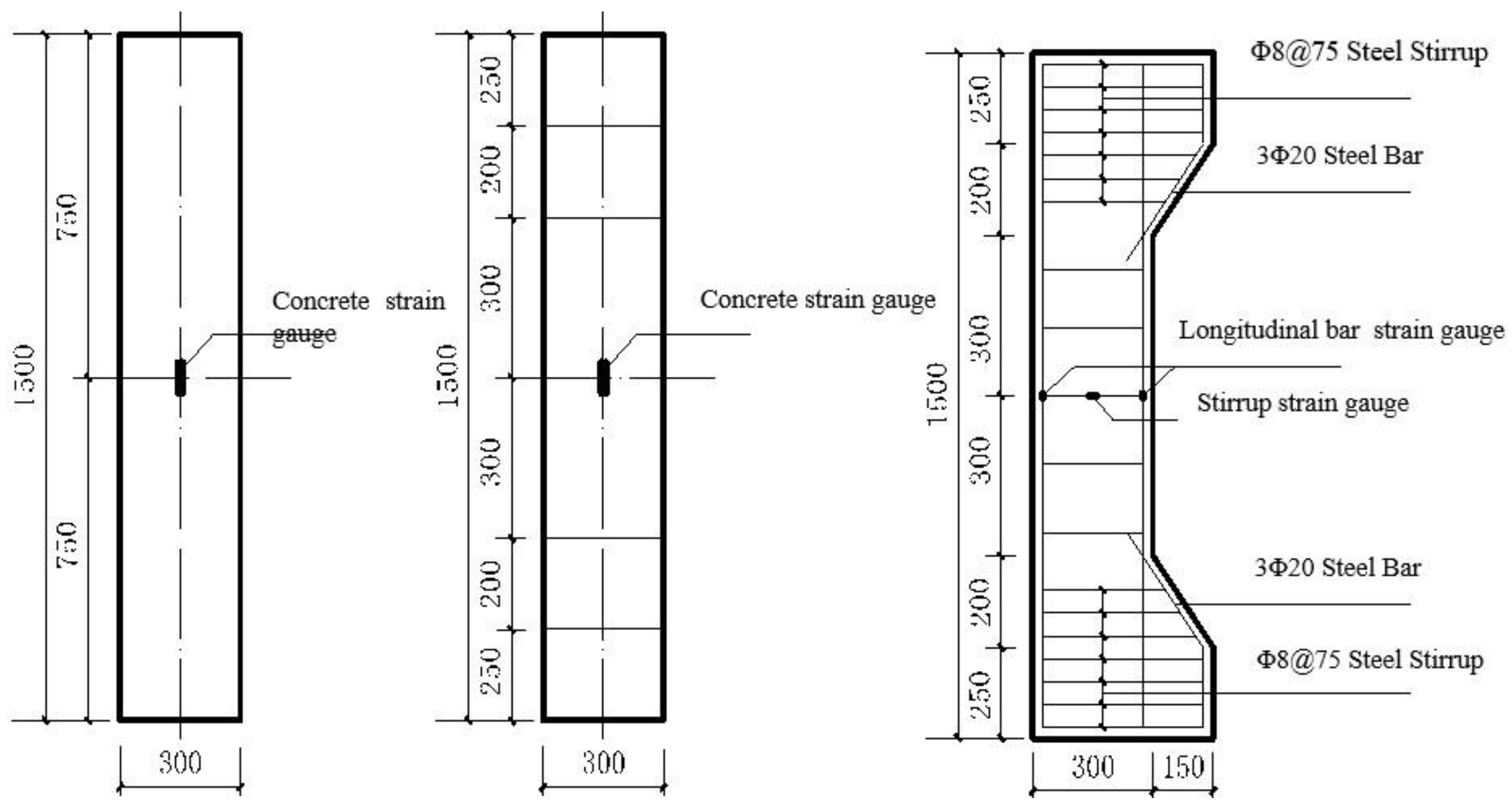
2.3. Test Setup and Loading
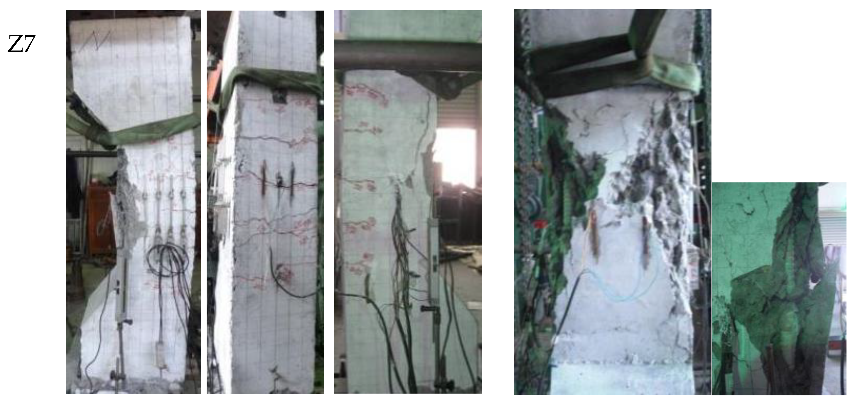
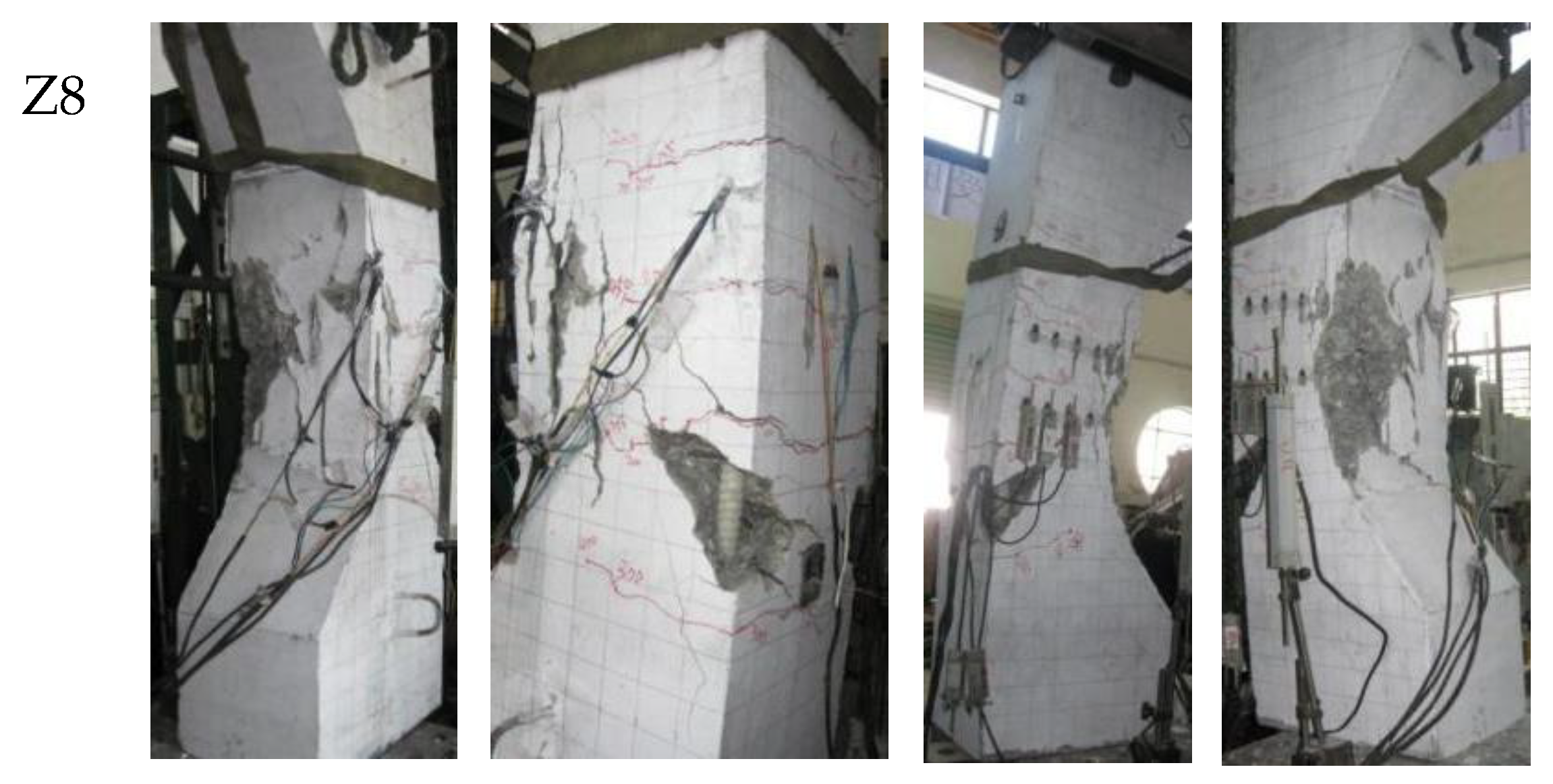
The test specimens were subjected to loading under a rigid MTS high-force load frame, which with a maximum compressive capacity of 10,000 kN. A schematic of the test set-up used is shown in Figure 2. Five displacement meters were arranged from top to bottom at the far side of the test piece from the load, and one displacement meter was arranged on both sides of the bending plane perpendicular to the test piece to measure the deflection of the specimen. In the middle section of the test piece, five rows of displacement meters were evenly arranged along the section height direction. The deformation under each load level was measured to verify the plane section assumption. Figure 3 shows the arrangement of the strain gauge measuring points. In the midspan section, the FRP bars and steel bars in tension were instrumented with strain gauges positioned before casting. An automatic data acquisition system was used to monitor loading, strain, and so on. At cracking and at each load increase, cracks were sketched and maximum crack width was measured using a microscope.
In the initial stage of the test, the load was controlled in stages, with the load in each stage being 20 kN, held for 10 min. The next level of the load was applied after the deformation stabilized. After the calculated ultimate load was attained, a displacement-controlled approach was adopted, and the loading rate was set to 2 mm/min.

2.4. Test Results

The test specimens were designed as large eccentrically loaded hybrid RC columns. During the test loading process, the concrete in the tensile zone of the middle section of the member cracked, and transverse cracks appeared when the pressure was increased to 0.1–0.15 Nu (ultimate load). With the increase in the pressure, more cracks were formed in the tensile zone of the cross-section, and they extended to the compression zone. The crack width increased, and the height of the compression zone decreased gradually. When the longitudinal pressure was increased to approximately 0.65–0.95 Nu, longitudinal cracks appeared in the compression zone, the concrete was crushed and started to fall off, and the deflection of the member increased evidently. With continuous loading, the lateral deformation of the specimen increased rapidly, and with the snapping or cracking of the concrete in the compression zone, the concrete was crushed considerably, and the bearing capacity decreased continuously, so the loading was stopped.
The test results showed that the failure of the hybrid RC columns in this test is similar to a “large eccentric compression failure” controlled by the tensile failure of RC columns. Table 5 and Table 6 list the test results. Figure 4, Figure 5 and Figure 6 show the different failure modes of the specimens.
The experimental results showed that all the concrete specimens exhibit crushing failure in the compression zone. When the ultimate bearing capacity was reached, most of the GFRP longitudinal bars in the compression and tensile zones remained intact, while the compressive GFRP bars of some members (Z4, Z5, Z7, and Z11) were damaged. This is because the specimens continue to bear the load after reaching the maximum bearing capacity. The failure of the GFRP bars is due to the loss of the restraint protection of concrete and the aggravation of member deformation. The failure location was between the two stirrups, and the tensile GFRP bars remained intact. After unloading, most of the cracks in the tensile zone were closed. During the entire loading process, the steel stirrups were maintained in a good condition, and the buckling of the longitudinal reinforcement and the failure of the GFRP bars were well restrained.
Table 6 lists the failure modes of each specimen. Table 7 summarizes the measurement results of the strain values in the ultimate state of the bearing capacity. Table 7 shows that the compressive strain at the edges of the concrete in the compression zone is in the range of 0.00225–0.00366 and that the maximum tensile strain of the longitudinal tensile GFRP bars is in the range of 0.00192–0.00640. The maximum tensile strain range of the longitudinal GFRP bars is in the range of 0.00147–0.00756, and the maximum compressive strain range is 0.00134–0.00412. In the test, the tensile and compressive steel bars reached the yield strength, and the strain range of the compressed GFRP bars was narrow, which can be converted to the effective utilization strength with a range of 50–153 MPa; it plays the role of a reinforcement. The tensile GFRP bars have a wide strain range, and the effective utilization strength is in the range of 60–305 MPa.

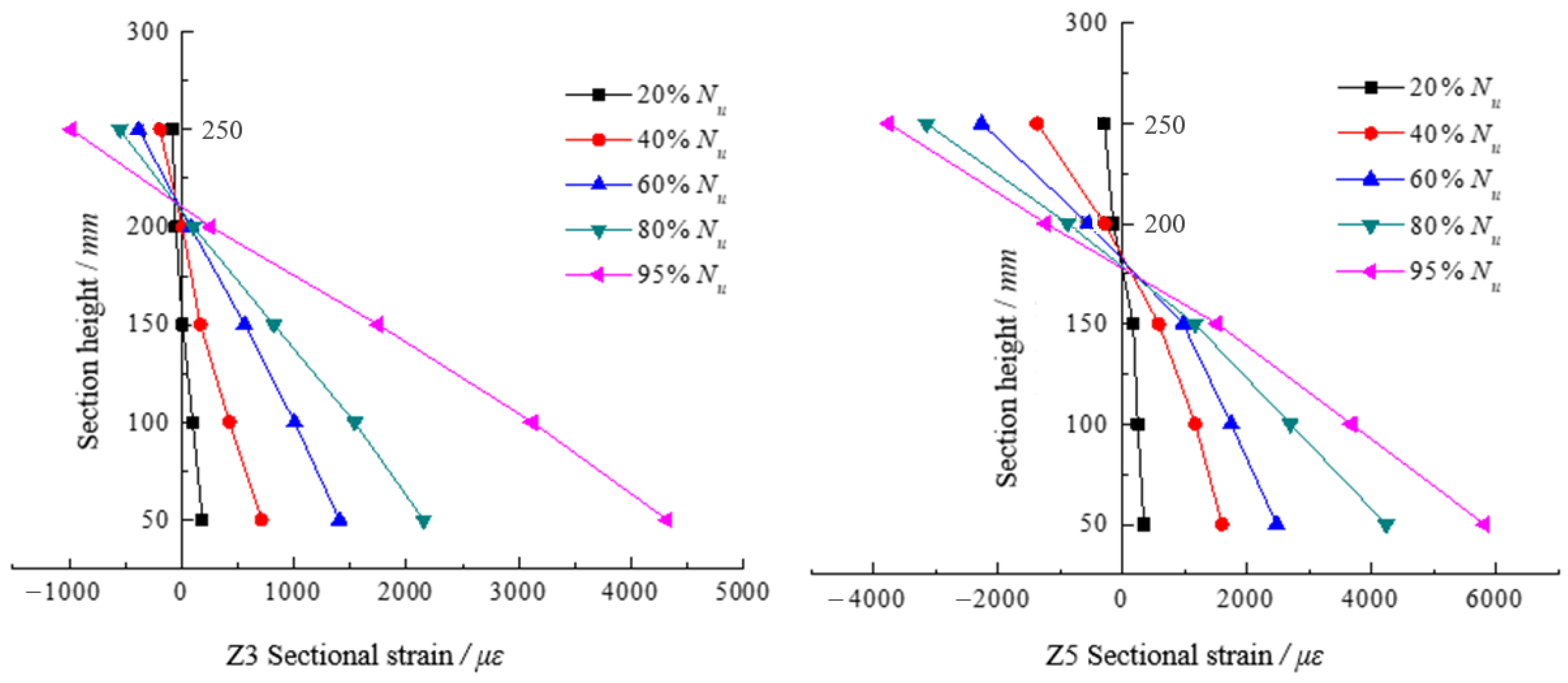
2.5. Verification of Plane Section Assumption

Figure 7 shows the average strain distribution at the section of eccentrically compressed concrete columns under different loads. When the load is low, the neutral axis is located near the middle of the section. With the increase in the load, the neutral axis position moves up after the concrete tension zone is cracked. At this time, the reinforcement in the tension area plays a role, and the neutral axis moves up gradually. The height of the compression area decreases with the increase in the load. From the beginning of loading to the failure of the columns, the average strain distribution of the cross-section is linear. The strain distribution of the midspan section of the columns approximately conforms to the plane section assumption. Therefore, when calculating the bearing capacity of eccentrically loaded columns, the plane section assumption can be adopted when the bond between the bars and concrete is good.

3. Calculation of Bearing Capacity

3.1. Basic Assumptions for Calculations

From the experimental phenomenon, the cross-section strain conforms to the plane section assumption. The failure mode of the test columns is similar to that of ordinary concrete columns under large eccentric compression. After the tensile bars yield (reaching the ultimate tensile yield), the relative compression side of the concrete reaches the ultimate compressive strain, and the concrete is crushed, at which point the column section is said to be destroyed.
The assumptions made for the calculations are similar to those made for the calculations of ordinary concrete compression columns:
  • Plane section assumption.
  • The tensile action of concrete is ignored.
  • The compressive stress of concrete is treated using the equivalent rectangle method, which is convenient for stress analyses.
  • The ultimate strain of concrete during crushing εcu = 0.0033.
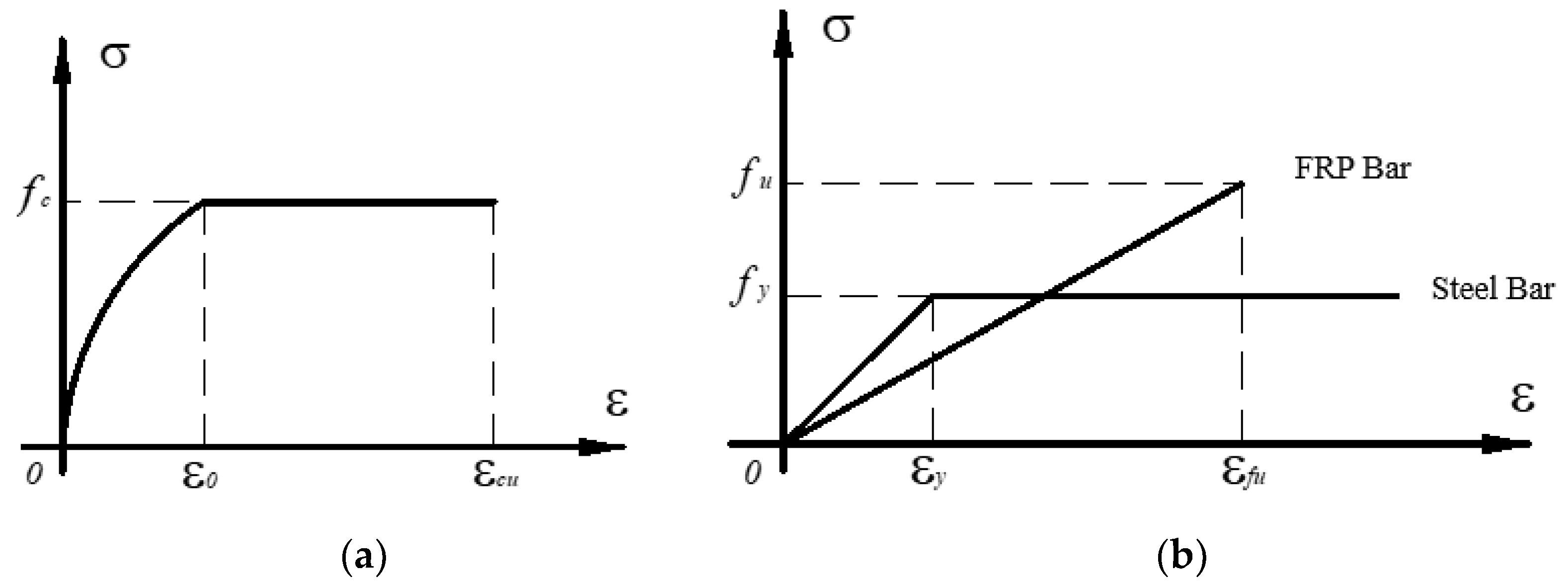
  • The constitutive relationship of longitudinal reinforcement and concrete is simplified as shown in Figure 8.
The stress–strain equation of the compressed concrete is as follows:
σ c = f c 1 1 ε c ε 0 2 ε c < ε 0 = 0.002 f c ε 0 ε c ε c u = 0.0033
In the formula, f c is the peak stress, ε 0 (=0.002) is the strain corresponding to the peak stress, and ε c u (=0.0033) is the ultimate compressive strain.
For the reinforcement under tension or compression, the two-line model is adopted:
σ s = E s ε s ε s < ε y f y ε y ε s ε u
FRP bars are elastic materials before failure, as shown in Figure 8b:
f f = E f ε f f f u     ( Under   tension )
In the formula, f f , E f , ε f , and f f u denote the tensile stress, tensile elastic modulus, tensile strain, and ultimate tensile stress of the FRP bars, respectively.
f f = E f ε f f f u     ( Under   pressure )
In the formula, E f , ε f and f f u are the compressive stress, compressive elastic modulus, compressive strain, and ultimate compressive stress of the FRP bars, respectively.

3.2. Boundary State

3.2.1. Failure Mode

The failure modes of eccentrically loaded SRC columns can be broadly divided into tension-controlled failure (large eccentricity compression failure) or compression-controlled failure (small eccentricity compression failure) based on whether the steel at the far end of the loading point yields. The deformation under tension-controlled failure is more evident than that under compression-controlled failure, and the early warning is stronger. Similar to SRC columns, the failure mode of eccentrically compressed hybrid RC columns can also be divided into two failure modes based on whether the reinforcement at the far end of the loading point yields or not: namely compression failure mode controlled by the crushing failure of concrete; or tensile failure mode controlled by the yielding of the tensile reinforcement following the yielding of the tensile steel. The strain relationship of discrimination are as follows:
(1)
If ε c = ε c u , ε s = ε f < ε y ; then failure mode controlled by compression (small eccentricity compression failure)
The failure characteristic is that the concrete under compression is crushed, and the steel bars far away from the point of application of the axial force may be under tension or compression, but they do not yield. The condition of small eccentric compression is that the eccentricity can be small or large; however, the quantity of reinforcement on the side of the axial force at the far end is considerable.
(2)
If ε c = ε c u , ε y < ε s = ε f < ε f u ; then failure mode controlled by tension (large eccentricity compression failure)
The failure characteristic is that the failure begins with the yielding of the tensile reinforcement, and the concrete continues to be stressed until its strain reaches the ultimate compressive strain at the edge of the compression zone. After the tensile reinforcement yields, the development of concrete tensile deformation is greater than that of compression deformation, and the neutral axis moves to the compression area. With the load continuing to increase, the concrete in the compression area exhibits longitudinal cracks and is crushed. In this failure mode, the eccentricity is large, and the reinforcement far away from the action point of the axial force is not excessive.
(3)
If ε c = ε c u , ε y = ε s = ε f < ε f u ; it is boundary failure I
The failure characteristic is that the concrete strain at the edge of the compression zone reaches the ultimate compressive strain when the tensile reinforcement yields at the same time, and this limit state is a balanced failure characterized by both large and small eccentricity compression.
(4)
If ε c = ε c u , ε y < ε s = ε f = ε f u ; it is boundary failure II
The failure characteristic is that the concrete strain at the edge of the compression zone reaches the ultimate compressive strain when the FRP bars break. This limit state can be used to prevent FRP bars from breaking suddenly due to large eccentricity and too few reinforcements.

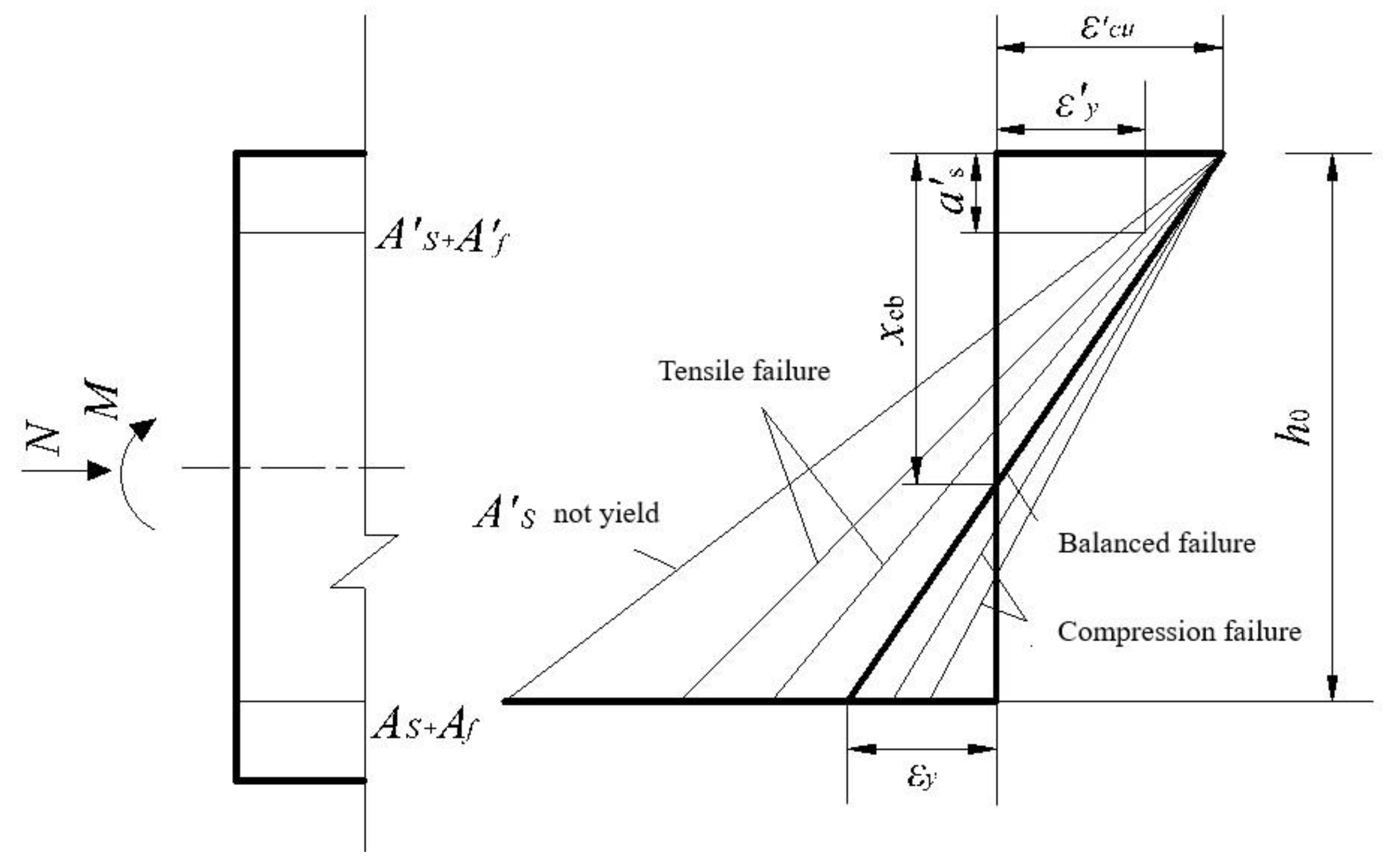
3.2.2. Discrimination of Large and Small Eccentric Compression Limits for Eccentrically Loaded Columns

Based on the assumption of plane section and the specified limit strain value of the compression edge, the average strain distribution along the section height of the normal section of the eccentric compression member under various failure conditions can be obtained, as shown in Figure 9.
There are two types of balanced states for eccentrically loaded hybrid RC columns:
(1)
Boundary state I: The compressive failure of concrete and the tensile yielding of the reinforcement occur simultaneously: when the reinforcement far away from the loading point yields in tension, the compressive concrete is just crushed. At this time, the height of the neutral axis in the section is x c b 1 , the height of the relative compression zone is ξ b 1 , and the calculation formulae are shown as follows in Equations (5)–(7).
x c b 1 h 0 = ε c u ε c u + ε y
x b 1 = β 1 x c b 1
ξ b 1 = x b 1 h 0 = β 1 1 + f y E s × ε c u
where β 1 is the equivalent rectangular stress figure coefficient.
(2)
Boundary state II: When the tensile FRP bars are broken, the concrete in the compression zone just reaches the ultimate compressive strain. The height of the relative compression zone is ξ b 2 , and the calculation is shown in Equation (8).
ξ b 2 = β 1 1 + f f u E s × ε c u
Generally, f f u > f y , therefore ξ b 1 > ξ b 2 .
The fundamental difference between large and small eccentric compression failures lies in whether the tensile reinforcement yields or not. When ξ ξ b 1 , the ultimate failure mode is small eccentricity compression; when ξ < ξ b 1 , the ultimate failure mode is large eccentricity compression. For large eccentric compression, if ξ ξ b 2 , the FRP bars on the tension side may break, and a brittle failure will occur.

4. Calculation Formula of Bearing Capacity

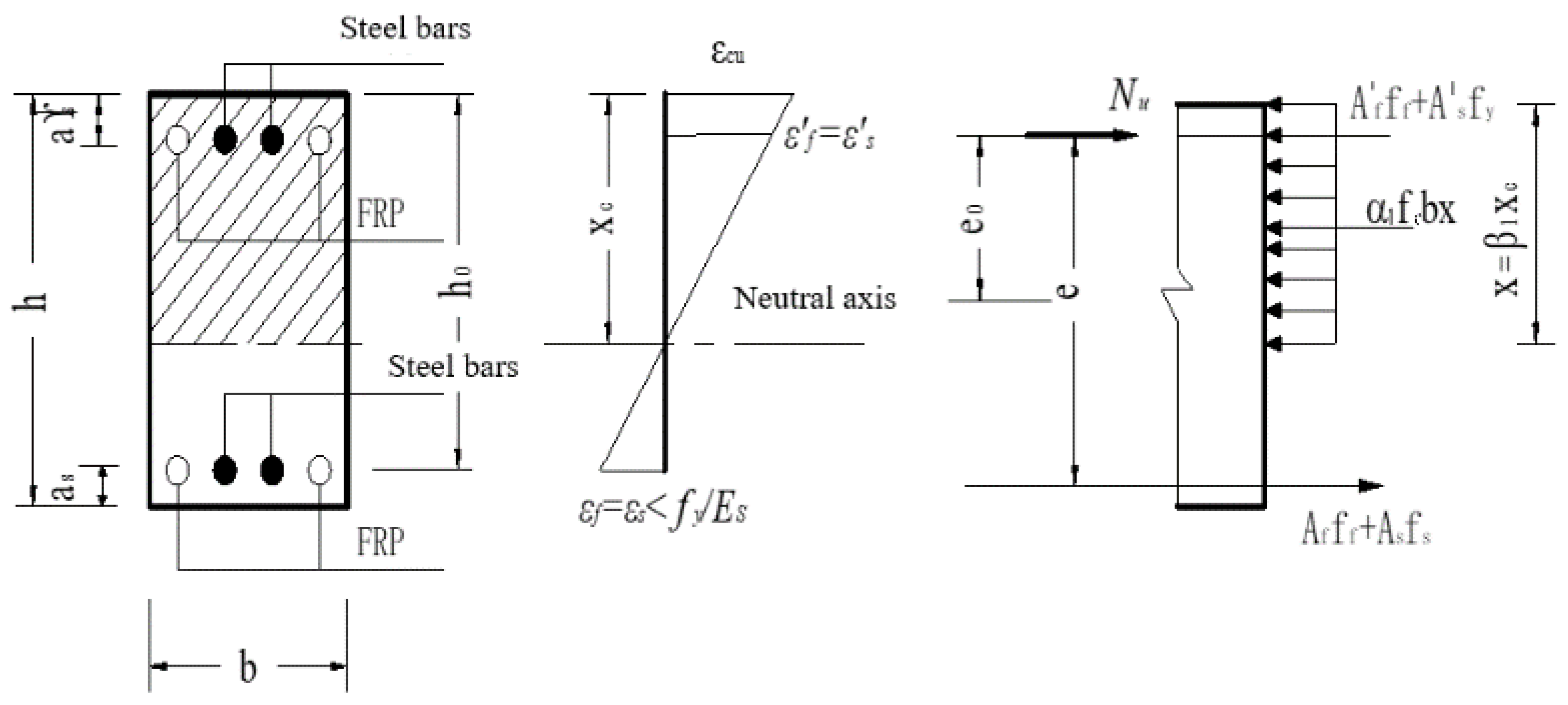
4.1. Large Eccentricity Compression

Figure 10 shows the stress of a large eccentricity compression section of the hybrid RC column. Based on the analysis of failure characteristics, the calculation formula for the section bearing capacity can be obtained.
X = 0 ,   N u = α 1 f c b x + A f f f + A s f y A s f y A f f f
M = 0 ,   N u e = α 1 f c b x ( h 0 0.5 x ) + ( A f f f + A s f y ) ( h 0 a s )
e = η s e i + 0.5 h a s
Based on the plane section assumption, we have:
ε c u ε f = x c h 0 x c
The stress of the FRP bars is calculated as follows:
2 a s x = β 1 x c ξ b h 0
f f = E f ε c u ( β 1 h 0 / x 1 )
f f = E f ε c u ( 1 β 1 a s / x )
Applicable conditions:
2 a s x ξ b h 0
In the formula, h 0 is the effective height of the section, x is the height of the compression zone in the Chinese code [34], α 1 is the equivalent rectangular stress figure coefficient, A f is the area of the FRP bars in the compression zone, A f is the area of the FRP bars in the tension zone of the section, A s is the area of the steel bars in the compression zone of the section, and A s is the area of the steel bars in the tension zone of the section. The bearing capacity of the section can be obtained by solving Equations (9) and (10) simultaneously.

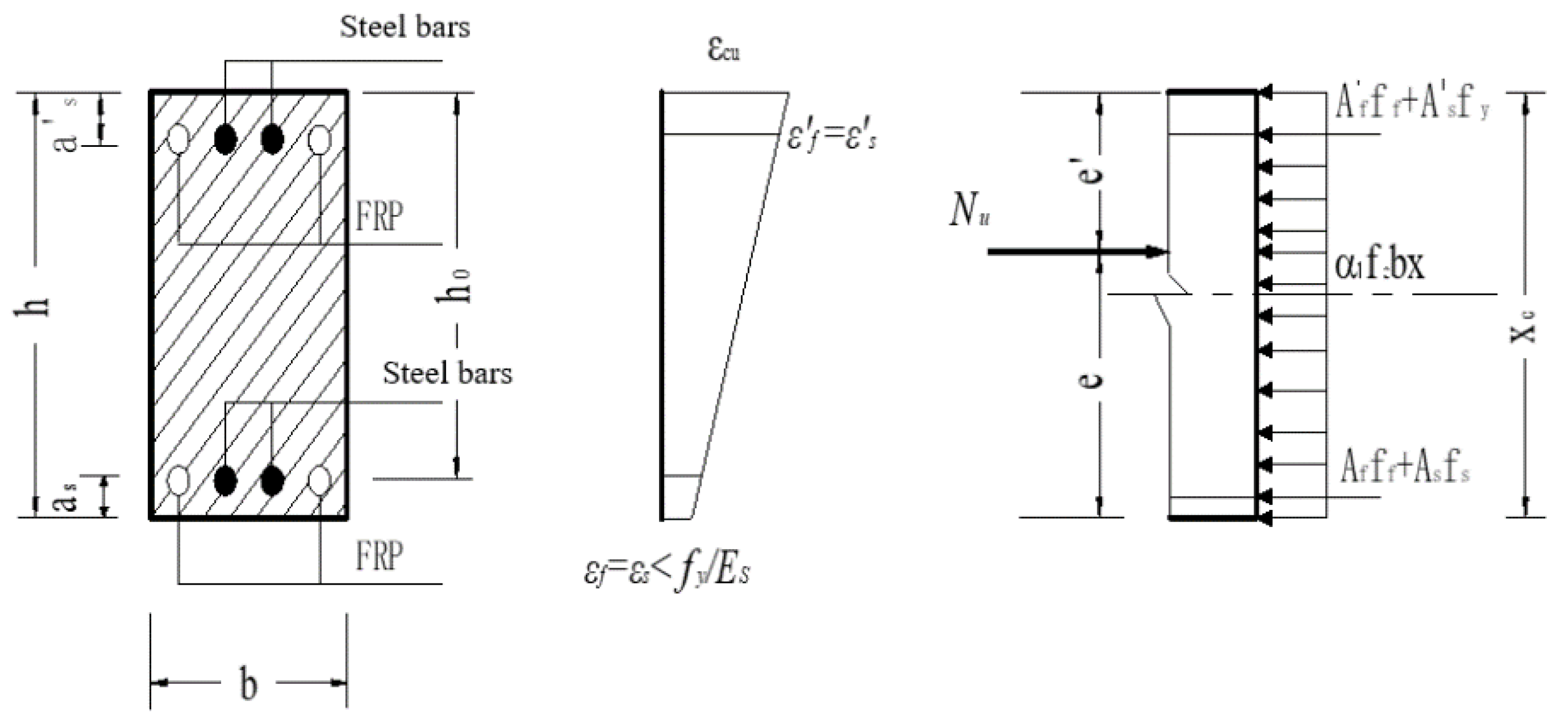
4.2. Small Eccentricity Compression

When the small eccentricity is compressed to the ultimate load, the reinforcement far away from the loading point may be subjected to tension or pressure, and the two cases correspond to different calculation formulae of the section bearing capacity.
(1)
At the time of failure, the reinforcement farther from the loading point is in tension, as shown in Figure 11.
X = 0 ,   N u = α 1 f c b x + A f f f + A s f y A s f s A f f f
M = 0 ,   N u e = α 1 f c b x ( h 0 0.5 x ) + ( A f f f + A s f y ) ( h 0 a s )
e = η s e i + 0.5 h a s
Based on the plane section assumption, we have:
ε c u ε f = x c h 0 x c
The tensile stress of the steel and FRP reinforcement are calculated as follows:
f s = E s ε c u ( β 1 h 0 x 1 )
f f = E f ε c u ( β 1 h 0 x 1 )
f f = E f ε c u ( 1 β 1 a s / x )
Applicable conditions:
x > ξ b h 0
The bearing capacity of the section can be obtained by solving Equations (17) and (18) simultaneously.
(2)
At the time of failure, the reinforcement farther from the loading point is under pressure, as shown in Figure 12.
X = 0 ,   N u = α 1 f c b x + A f f f + A s f y + A s f s + A f f f
M = 0 ,   N u e = α 1 f c b x ( h 0 0.5 x ) + ( A f f f + A s f y ) ( h 0 a s )
e = η s e i + 0.5 h a s
Based on the plane section assumption, we have:
ε c u ε f = x c x c h 0
The compressive stress of the reinforcement farther from the loading point and the stress of the FRP reinforcement can be calculated as follows:
f s = E s ε c u ( 1 β 1 h 0 x )
f f = E f ε c u ( 1 β 1 h 0 x )
f f = E f ε c u ( 1 β 1 a s / x )
Applicable conditions as shown in Equation (24). The bearing capacity of the section can be obtained by solving Equations (25) and (26) simultaneously.

4.3. Boundary Failure State

Based on the plane section assumption, we have:
x b = ε c u f y / E s + ε c u β 1 h 0
The compressive stress of the reinforcement farthest from the loading point and the stress of the FRP bars are calculated as follows:
f s = f y
f f = E f ε s = E f f y / E s
f s = f y
f f = E f ε c u ( 1 β 1 a s / x b )
Equilibrium equations:
N b = α 1 f c x b b + A f f f + A s f y A s f y A f E f f y / E s
N b e = α 1 f c x b b ( h 0 0.5 x b ) + A f E f ε 0 ( h 0 a s ) + A s f y ( h 0 a s )
Generally, when N u < N b , a tensile failure mode controlled by the yielding of the tensile steel occurs; when N u > N b , a compression failure mode controlled by the crushing failure of concrete occurs.

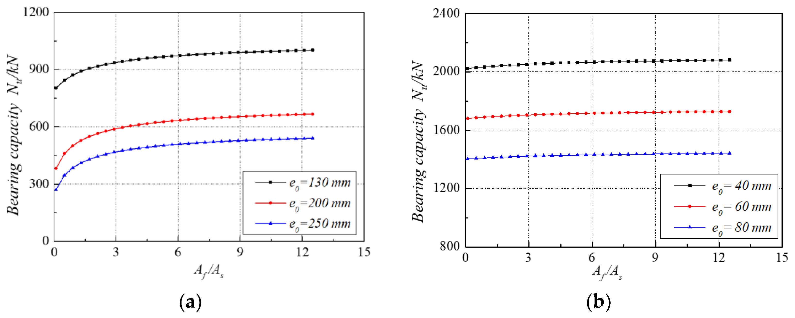
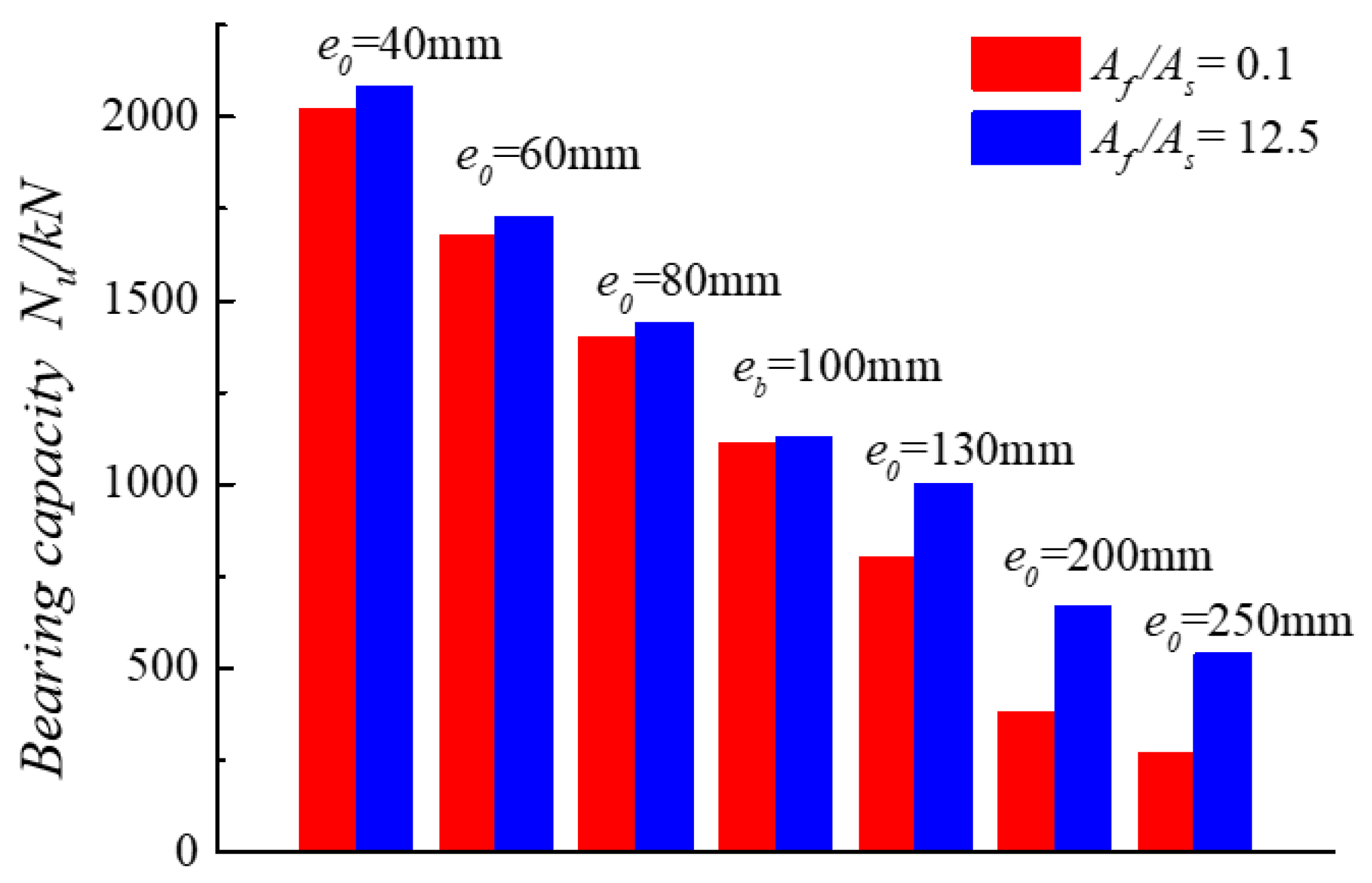
4.4. Effect of Cross-Section Reinforcement Ratio

Based on the equal stiffness principle, the effective reinforcement ratio ρsf,E [15] is defined as shown in Equation (39):
ρ s f , E = ρ s + E f / E s ρ f
ρ s = A s / b d = steel reinforcement ratio; ρ f = A f / b d = FRP reinforcement ratio.
Another important index of longitudinal reinforcement stiffness ratio (Rf) is defined as shown in Equation (40). Clearly, once the reinforcement types are determined, R f is a function of the parameter A f / A s .
R f = E f A f E s A s
Based on theoretical analysis, it was found that if two concrete columns are designed with equal effective reinforcement ratio, there are some differences in bearing capacity when the parameter A f / A s changes.
In this subsection, the theoretical results of bearing capacity of the hybrid RC eccentric compression columns and the corresponding SRC eccentric compression columns will be compared. The section reinforcement ratio mentioned in this section, without special instructions, refers to the section reinforcement ratio of the section tensile zone. The bearing capacity of hybrid RC eccentric compression columns with different eccentricity distances is calculated and analyzed, using the test column specimen Z3 parameters as a standard to understand the trend of the bearing capacity when the cross-section reinforcement ratio varies between 0.1 and 12.5 for reference in practical applications.
The information of column specimen Z3 for theoretical analysis is as follows: symmetric reinforcement, effective reinforcement ratio of longitudinal reinforcement ρ s f , E = 0.7 % , concrete strength f c = 35.1   MPa , yield strength of steel reinforcement f y = 375   MPa , section size b × h = 300   mm × 300   mm , a s = a s = 25   mm , cross-section reinforcement ratio A f / A s = 8.7 , and the design parameters of GFRP reinforcement are E f = 40.4   GPa , E f = 37   GPa , f f < f f u , f f < f f u . For theoretical analysis, only one parameter is varied at one time.
Figure 13 shows the influence of different eccentricity distances on bearing capacity of hybrid RC columns.
It can be seen from Figure 13a that in the case of large eccentric compression, with the same effective reinforcement ratio and different eccentricity distances, the load-carrying capacity of hybrid RC columns increases with the increase in the section reinforcement ratio, whereas the load-carrying capacity of the columns decreases with the increase in the section eccentricity distance for the same section reinforcement ratio.
From Figure 13b, it can be seen that in the case of small eccentric compression, the effective reinforcement ratio is the same, and the load-carrying capacity of hybrid RC columns with different eccentricity distances will also increase with the increase in cross-section reinforcement ratio, but the effect of the increase is not obvious, and the curve in the figure is close to the horizontal line; and at the same cross-section reinforcement ratio, with the decrease in cross-section eccentricity distance, the column’s compressive load-carrying capacity of the normal section increases.
Figure 14 gives a comparison of different cross-section reinforcement ratios corresponding to different eccentricity distances under the same effective reinforcement rate. It can be seen that the enhancement of FRP bars within the hybrid reinforced concrete section is significant in the case of large eccentric compression ( e 0 > e b ).

4.5. Comparison between Experimental and Theoretical Results

Table 8 compares the value of the bearing capacity of the tested columns with the theoretical value obtained using the calculation formula proposed in this paper. The table of results shows that the theoretical value calculated using the recommended formula is less than the test value, with a low standard deviation and coefficient of variation. Thus, the recommended calculation formula provides a sufficiently reliable and conservative estimation.

5. Conclusions

The mechanical behavior and computed bearing capacity of hybrid RC columns under eccentric loading were analyzed in this work. The following conclusions can be drawn from the results:
(1)
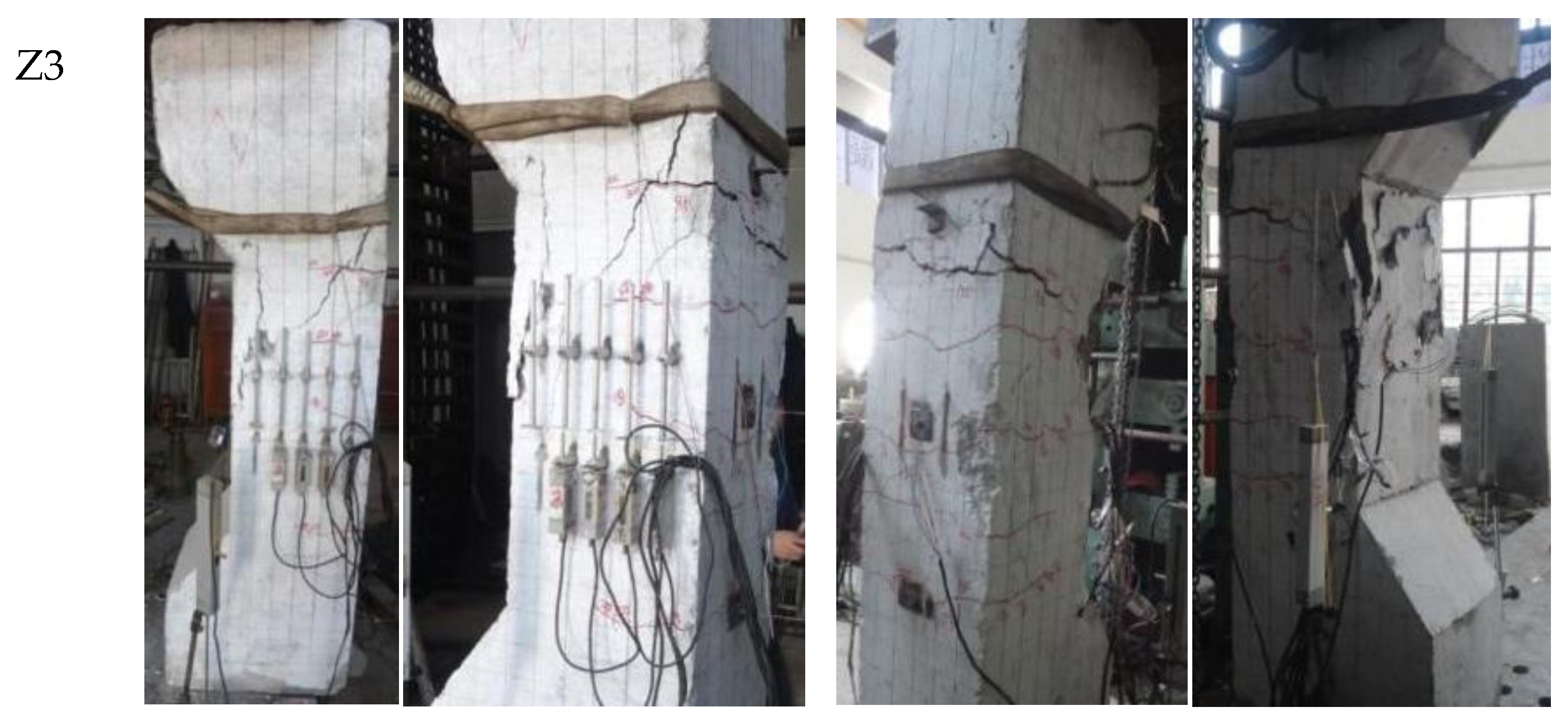
Based on the equal stiffness principle, ten hybrid RC columns under large eccentric loading are designed. The failure processes of all specimens are similar to that of RC columns subjected to large eccentric compression load. The failure mode was ductile, namely, the steel rebars in the tensile zone firstly yielded, while the FRP bars in the tensile zone remained in a tensile state, and at last the concrete on the compression side was crushed.
(2)
The test results showed that the ultimate bearing capacity of the columns decreases with the increase in eccentricity. However, the impact of the varying axial stiffness ratio between GFRP and steel bars on the bearing capacity can be considered negligible.
(3)
Theoretical analysis showed that the failure mode of hybrid RC columns also could be divided into large eccentricity compression failure and small eccentricity compression failure based on whether the reinforcement on the relatively tensile side (the side far away from the axial force) yields or not, but there were two boundary failure states.
(4)
The tests have verified the assumption of the plane section and, based on it, two relative heights of the compression zone ( ξ b 1 and ξ b 2 could be calculated, corresponding two different boundary failure states. ξ b 1 was used as a criterion to judge the failure mode, and ξ b 2 was used as a limiting condition to prevent FRP bars from breaking suddenly.
(5)
Theoretical analysis showed that the enhancement effect of FRP bars in a hybrid RC section is more significant in the case of large eccentric compression than the case of small eccentric compression.
(6)
Calculation formulae for the bearing capacity of eccentrically compressed hybrid RC columns were proposed. The calculated values were in good agreement with the experimental values.

Author Contributions

Conceptualization, L.P. and W.Q.; Methodology, L.P.; Validation, L.P. and Z.L.; Formal analysis, L.P., Z.H. and S.D.; Investigation, L.P., Z.H., J.X. and Z.L.; Resources, L.P. and S.D.; Data curation, L.P., Z.L., W.Q. and S.D.; Writing—original draft, L.P.; Writing—review and editing, Z.H.; Supervision, J.X. and W.Q.; Funding acquisition, J.X. All authors have read and agreed to the published version of the manuscript.

Funding

The authors are appreciated for the financial support provided by the National Natural Science Foundation of China with No. 52278160 and Shaanxi Natural Science Foundation with Grant No. 2014JM7278; 2018JQ-5005; 2021 JM-179, and Guangdong Natural Science Foundation with Grant No. 2023A1515012081.

Data Availability Statement

The data that support the findings of this study are available from the corresponding author upon reasonable request.

Conflicts of Interest

The authors declare no conflicts of interest.

Nomenclature

The following symbols are used in this paper:
A f area of the FRP bars in the tension zone of the section
A s   area of the steel bars in the tension zone of the section
A s area of the steel bars in the compression zone of the section
A f area of the FRP bars in the compression zone of the section
Daverage crack spacing
eeccentric distance
E f tensile elastic modulus of the FRP bars
E s modulus of elasticity of steel reinforcement
E f compressive elastic modulus of the FRP bars
f f u ultimate compressive stress of the FRP bars
f f u ultimate tensile stress of the FRP bars
f f compressive stress of the FRP bars
h 0 effective height of the section
M y bending moment of control cross-section
M u bending moment of control cross-section
N y axial load
N u ultimate load
N b balance the axial force in the event of failure
Nu,eexperimental data
Nu,t1theoretical data
V y column lateral deflection
V u column lateral deflection
xheight of the compression zone
xcb1the height of the neutral axis in the section
α 1 equivalent rectangular stress figure coefficient
β 1 equivalent rectangular stress figure coefficient
ε y yielding strain of steel reinforcement
ε u ultimate strain of FRP bars
ε s u maximum tensile strain of steel bar
ε f u maximum tensile strain of GFRP bar
ε s u maximum compressive strain of steel bar
ε f u maximum compressive strain GFRP bar
ε c u maximum compressive strain of concrete
ε 0 strain corresponding to the peak stress
ε f compressive strain of the FRP bars
ε f tensile strain of the FRP bars
ε s strain of steel reinforcement
ξ b 1 the height of the relative compression zone under boundary state 1
ξ b 2 the height of the relative compression zone under boundary state 2
ρ s f , E effective reinforcement ratio

References

  1. Deng, B.Y.; Li, L.Z.; Tan, D.; Uddin, M.N.; Cai, Z.W.; Yu, K.Q. Sustainable and cost-effective ultra-lightweight engineered cementitious composite: Design and material characterization. Cem. Concr. Compos. 2023, 136, 104895. [Google Scholar] [CrossRef]
  2. Xiao, J.; Huang, L.; He, Z.; Qu, W.; Li, L.; Jiang, H.; Zhong, Z.; Long, X. Probabilistic models applied to concrete corrosion depth prediction under sulfuric acid environment. Measurement 2024, 234, 114807. [Google Scholar] [CrossRef]
  3. Xiao, J.; Zeng, H.; Huang, H.; Liu, L.; Li, L.; Yuan, B.; Zhong, Z. Experimental Investigation on the Influence of Strength Grade on the Surface Fractal Dimension of Concrete under Sulfuric Acid Attack. Buildings 2024, 14, 713. [Google Scholar] [CrossRef]
  4. Zhou, B.; Wu, R.; Feng, J.; Yin, S. Modeling of tensile behavior of hybrid GFRP-steel reinforced concrete chords. Compos. Struct. 2020, 236, 111853. [Google Scholar] [CrossRef]
  5. Scattarreggia, N.; Malomo, D.; DeJong, M.J. A new Distinct Element meso-model for simulating the rocking-dominated seismic response of RC columns. Earthq. Eng. Struct. Dyn. 2023, 52, 828–838. [Google Scholar] [CrossRef]
  6. Scattarreggia, N.; Qiao, T.Y.; Malomo, D. Earthquake Response Modeling of Corroded Reinforced Concrete Hollow-Section Piers via Simplified Fiber-Based FE Analysis. Sustainability 2021, 13, 9342. [Google Scholar] [CrossRef]
  7. Wu, G.; Dong, Z.; Wang, X.; Zhu, Y.; Wu, Z. Prediction of Long-Term Performance and Durability of BFRP Bars under the Combined Effect of Sustained Load and Corrosive Solutions. J. Compos. Constr. 2015, 19, 4014058. [Google Scholar] [CrossRef]
  8. Ibrahim, M.; Asadian, A.; Galal, K. A simplified approach for design of steel-GFRP hybrid reinforced concrete sections. Eng. Struct. 2023, 278, 115352. [Google Scholar] [CrossRef]
  9. Xu, J.; Zhu, P.; Ma, Z.J.; Qu, W. Fatigue flexural analysis of concrete beams reinforced with hybrid GFRP and steel bars. Eng. Struct. 2019, 199, 109635. [Google Scholar] [CrossRef]
  10. Fan, X.; Zhang, M. Behaviour of inorganic polymer concrete columns reinforced with basalt FRP bars under eccentric compression: An experimental study. Compos. Part B Eng. 2016, 104, 44–56. [Google Scholar] [CrossRef]
  11. Sim, J.; Park, C.; Moon, D.Y. Characteristics of basalt fiber as a strengthening material for concrete structures. Compos. Part B Eng. 2005, 36, 504–512. [Google Scholar] [CrossRef]
  12. Lu, C.; Qi, Z.; Zheng, Y.; Xuan, G.; Yan, Y. Long-term tensile performance of GFRP bars in loaded concrete and aggressive solutions. J. Build. Eng. 2023, 64, 105587. [Google Scholar] [CrossRef]
  13. Kara, I.F.; Ashour, A.F.; Köroğlu, M.A. Flexural behavior of hybrid FRP/steel reinforced concrete beams. Compos. Struct. 2015, 129, 111–121. [Google Scholar] [CrossRef]
  14. Zhu, P.; Xu, J.; Qu, W.; Hao, H. Experimental Study of Fatigue Flexural Performance of Concrete Beams Reinforced with Hybrid GFRP and Steel Bars. J. Compos. Constr. 2017, 21, 4017036. [Google Scholar] [CrossRef]
  15. Qu, W.; Zhang, X.; Huang, H. Flexural Behavior of Concrete Beams Reinforced with Hybrid (GFRP and Steel) Bars. J. Compos. Constr. 2009, 13, 350–359. [Google Scholar] [CrossRef]
  16. Pang, L.; Qu, W.; Zhu, P.; Xu, J. Design Propositions for Hybrid FRP-Steel Reinforced Concrete Beams. J. Compos. Constr. 2016, 20, 4015086. [Google Scholar] [CrossRef]
  17. Gu, X.; Dai, Y.; Jiang, J. Flexural behavior investigation of steel-GFRP hybrid-reinforced concrete beams based on experimental and numerical methods. Eng. Struct. 2020, 206, 110117. [Google Scholar]
  18. Lu, C.; Cai, Q.; Xu, K.; Sha, X.; Yan, Y. Comparison of flexural behaviors between plain and steel-fiber-reinforced concrete beams with hybrid GFRP and steel bars. Structures 2022, 43, 1–11. [Google Scholar] [CrossRef]
  19. Moolaei, S.; Sharbatdar, M.K.; Kheyroddin, A. Experimental evaluation of flexural behavior of HPFRCC beams reinforced with hybrid steel and GFRP bars. Compos. Struct. 2021, 275, 114503. [Google Scholar] [CrossRef]
  20. Aiello, M.A.; Ombres, L. Structural Performances of Concrete Beams with Hybrid (Fiber-Reinforced Polymer-Steel) Reinforcements. J. Compos. Constr. 2002, 6, 133–140. [Google Scholar] [CrossRef]
  21. Lau, D.; Pam, H.J. Experimental study of hybrid FRP reinforced concrete beams. Eng. Struct. 2010, 32, 3857–3865. [Google Scholar] [CrossRef]
  22. De Luca, A.; Matta, F.; Nanni, A. Behavior of Full-Scale Glass Fiber-Reinforced Polymer Reinforced Concrete Columns under Axial Load. ACI Struct. J. 2010, 107, 589–596. [Google Scholar]
  23. Tobbi, H.; Farghaly, A.S.; Benmokrane, B. Concrete Columns Reinforced Longitudinally and Transversally with Glass Fiber-Reinforced Polymer Bars. ACI Struct. J. 2012, 109, 551–558. [Google Scholar]
  24. Tobbi, H.; Farghaly, A.S.; Benmokrane, B. Strength Model for Concrete Columns Reinforced with Fiber-Reinforced Polymer Bars and Ties. ACI Struct. J. 2014, 111, 789–798. [Google Scholar] [CrossRef]
  25. Mohamed, H.M.; Afifi, M.Z.; Benmokrane, B. Performance Evaluation of Concrete Columns Reinforced Longitudinally with FRP Bars and Confined with FRP Hoops and Spirals under Axial Load. J. Bridge Eng. 2014, 19, 4014020. [Google Scholar] [CrossRef]
  26. Hamed, R.Z.; Hassan, H.F. Structural behavior of GFRP-RC slender columns under various eccentricity loading conditions. Civ. Environ. Eng. 2023, 19, 1–16. [Google Scholar] [CrossRef]
  27. Xue, W.C.; Peng, F.; Fang, Z.Q. Behavior and Design of Slender Rectangular Concrete Columns Longitudinally Reinforced with Fiber-Reinforced Polymer Bars. ACI Struct. J. 2018, 115, 311–322. [Google Scholar] [CrossRef]
  28. Choo, C.C.; Harik, I.E.; Gesund, H. Strength of rectangular concrete columns reinforced with fiber-reinforced polymer bars. ACI Struct. J. 2006, 103, 452–459. [Google Scholar]
  29. Choo, C.C.; Harik, I.E.; Gesund, H. Minimum reinforcement ratio for fiber-reinforced polymer reinforced concrete rectangular columns. ACI Struct. J. 2006, 103, 460–466. [Google Scholar]
  30. Zadeh, H.J.; Nanni, A. Flexural stiffness and second-order effects in fiber-reinforced polymer-reinforced concrete frames. ACI Mater. J. 2017, 114, 533–544. [Google Scholar]
  31. Peng, F.; Xue, W. Calculation approach of ultimate capacity of FRP reinforced concrete columns under eccentric compression. Jianzhu Jiegou Xuebao/J. Build. Struct. 2018, 39, 147–155. [Google Scholar]
  32. Roudsari, S.S.; Ungureanu, L.M.; Soroushnia, S.; Abu-Lebdeh, T.; Petrescu, F.I.T. Optimization of fiber-reinforced polymer bars for reinforced concrete column using nonlinear finite element algorithms. Algorithms, 2022; 15, 12. [Google Scholar] [CrossRef]
  33. Ibrahim, A.M.A.; Wu, Z.; Fahmy, M.F.M.; Kamal, D. Experimental Study on Cyclic Response of Concrete Bridge Columns Reinforced by Steel and Basalt FRP Reinforcements. J. Compos. Constr. 2016, 20, 4015062. [Google Scholar] [CrossRef]
  34. GB 50010-2010; Code for Design Concrete Structures. Ministry of Construction of the People’s Republic of China, China Building Industry Press: Beijing, China, 2015.
Figure 1. Cross-sections of eccentrically compressed hybrid RC columns.
Buildings 14 02472 g001
Figure 2. Loading devices for tests on eccentrically compressed hybrid RC columns.
Buildings 14 02472 g002
Figure 3. Strain gauge arrangement of a hybrid RC specimen under eccentric compression.
Buildings 14 02472 g003
Figure 4. Failure mode of hybrid RC column Z3.
Buildings 14 02472 g004
Figure 5. Failure mode of hybrid RC column Z7.
Buildings 14 02472 g005
Figure 6. Failure mode of hybrid RC column Z8.
Buildings 14 02472 g006
Figure 7. Sectional strain in the middle region of the hybrid RC columns (Z3, Z5, Z6, and Z7).
Buildings 14 02472 g007aBuildings 14 02472 g007b
Figure 8. Constitutive relationship of each material. (a) Stress–strain curve of compressed concrete; (b) Stress–strain curve of reinforcement.
Buildings 14 02472 g008
Figure 9. Average strain distribution of eccentrically loaded members.
Buildings 14 02472 g009
Figure 10. Stress of large eccentric compression section of the hybrid RC column.
Buildings 14 02472 g010
Figure 11. Stress of small eccentric compression section (the distal reinforcement is in tension).
Buildings 14 02472 g011
Figure 12. Stress of small eccentric compression section (the distal reinforcement is under pressure).
Buildings 14 02472 g012
Figure 13. The Variation of Bearing Capacity for hybrid RC Columns with Different Eccentricities: (a) large eccentricity compression; (b) small eccentricity compression.
Buildings 14 02472 g013
Figure 14. Comparison of the effect of section reinforcement ratios for different eccentricity distances.
Buildings 14 02472 g014
Table 1. Structural parameters of eccentrically compressed column.
Specimen Number e / mm A s / mm 2 A f / mm 2 ρ s f , E / % [15] f c u 0 / MPa
Z3200226.219640.6746.2
Z4110226.219640.6746.2
Z5130226.219640.6746.2
Z6200226.219640.6727.3
Z7130226.219640.6727.3
Z8200113.124550.6646.2
Z9200452.419640.9246.2
Z10200339.324550.9146.2
Z11200678.619641.1846.2
Z12200452.429461.1446.2
Table 2. Parameters of the steel bars.
Model d / mm f y / MPa f u / MPa E s / GPa ε y / % ε u / %
HRB335123755552000.1875>10
HPB23583004652050.1463>10
Table 3. Tensile properties of GFRP bars.
d / mm f u / MPa E f / GPa ε u / %
2583740.42.09
Table 4. Compression behavior of end-reinforced GFRP bars.
Model d / mm Loading Method H / mm f u / MPa E f / GPa ε u / %
GFRP Bars25End-strengthening method194535————
138394371.06
Table 5. Summary of crack development in eccentrically loaded hybrid RC column specimens.
Specimen NumberHorizontal Cracking Load
Ncr/kN
Vertical Cracking Load
Ncr/kN
Nu/kNCrack Width
d/mm
Average Crack Spacing
D/cm
Remarks
Z3853406780.1213.9——
Z4220100012450.0814.9Longitudinal cracking of compressed GFRP bars
Z518096010640.1016.3Same as Z4
Z61003405640.0614.3——
Z72506307280.0514.0Same as Z4
Z81204507860.1014.3——
Z91755007760.0512.3——
Z101256107900.1013.8——
Z111758308540.1013.9Same as Z4
Z12906508430.1013.3——
Note: The crack width in the table is the maximum horizontal crack width corresponding to the vertical crack; the crack spacing is the average crack spacing measured after unloading; the GFRP bar of the specimen without any remark is intact.
Table 6. Failure mode of eccentrically loaded hybrid RC columns.
Specimen NumberTensile Reinforcement Yield εs = 1875 μεMaximum Bearing CapacityFailure Mode
Axial Load
Ny/kN
Column Lateral Deflection Vy/mmBending Moment of Control Cross-Section My/kN·mUltimate Load Nu/kNColumn Lateral Deflection Vu/mmBending Moment of Control Cross-Section Mu/kN·m
Z3343.01.769.26786.5140.0A
Z41180.52.3132.612452.7140.3A
Z5721.51.594.910643.9142.5A
Z6299.01.760.356417.8122.8B
Z7539.52.271.37286.299.2B
Z8388.01.878.37865.9161.8C
Z9382.51.577.17765.1159.2B
Z10342.51.469.07905.3162.2A
Z11398.51.780.48546.1176.0A
Z12447.51.089.98434.3172.2A
Note: The failure mode A indicates that the tensile steel bars yield first, and the yielding of the compressive steel bars occurs almost simultaneously with the crushing of the concrete. Failure mode B means that the tensile steel bars yield first, then the compression steel bars yield, and finally, the concrete is crushed. In the failure mode C (there is no steel reinforcement on the tensile side of the Z8 section), the tensile GFRP bar is undamaged, and its strain is greater than the yield strain of the reinforcement. The compressive steel bars yield, and finally, the concrete is crushed. At this time, the strain of the tensile GFRP is equal to the yield strain.
Table 7. Strain of eccentrically loaded damaged hybrid RC column specimens.
Specimen NumberMaximum Tensile Strain of Longitudinal BarMaximum Compressive Strain of Longitudinal BarMaximum Compressive Strain of Concrete
εcu/με
Steel Bar
εsu/με
GFRP Bar
εfu/με
Steel Bar
ε s u /με
GFRP Bar
ε f u /με
Z350304829−1881−2505−3631
Z419211473−1847−1355−3424
Z564032648−1993−2836−2750
Z643517557−6977−4139−2253
Z723902650−3312−2919−3010
Z8——2836−2435−1343−3657
Z928002943−3396−2027−3525
Z1038572460−1932−2442−2634
Z1146704577−1966−2406−3420
Z1258173086−1862−1605−3234
Table 8. Comparison between experimental and theoretical data of the column bearing capacity.
Specimen Number A f / A s Longitudinal Reinforcement Stiffness Ratio (Rf)Experimental Data
Nu,e/kN
Theoretical Data
Nu,t1/kN
Nu,t1/Nu,e
Z38.71.8678647.10.96
Z48.71.812451150.30.92
Z58.71.81064982.70.92
Z68.71.8564475.20.84
Z78.71.8728693.30.95
Z821.74.4786691.00.88
Z94.30.9776698.60.90
Z107.21.5790738.90.94
Z112.90.6854750.20.88
Z126.51.3843789.30.94
Average0.91
Standard deviation0.04
Coefficient of variation0.044
Disclaimer/Publisher’s Note: The statements, opinions and data contained in all publications are solely those of the individual author(s) and contributor(s) and not of MDPI and/or the editor(s). MDPI and/or the editor(s) disclaim responsibility for any injury to people or property resulting from any ideas, methods, instructions or products referred to in the content.

