Abstract
Indoor air quality determines the comfort, health, and wellbeing of people in buildings. Windows are the optimal elements for providing natural ventilation and fresh air, but the outside contains suspended particles that can be harmful in high concentrations. This work presents an openable and double-glazed façade component with a cavity that includes a series of slats that filter the air and depurate it by means of a photocatalytic reaction (TiO2). This component integrates the functions of ventilation, solar protection, and air purification, which were analysed in the slat and the façade component to approve a preliminary design. To this end, it was applied to a specific case, a non-residential building at a latitude 41° N in a Mediterranean climate. The results show the optimal dimensions according to solar radiation and ventilation in this specific case and the method used to obtain them, along with the increase in the temperature of the incoming air with respect to the outside (10 °C). Finally, the results obtained from a photocatalytic coating sample show that the NOx degradation can be up to 9%. All these results confirm the applicability of this component in buildings and pave the way for further research.
1. Introduction
The pandemic situation caused by the SARS-CoV-2 in 2020 brought the importance of health in buildings to the forefront. In this line, the International Law of Human Rights recognises everyone’s right to adequate housing and states that “housing is not adequate if it does not guarantee physical safety or provide adequate space, as well as protection against the cold, damp, heat, rain, wind, other threats to health and structural hazards” [1].
Indoor air quality (IAQ) is standardised by building regulations in different countries, which specify the rates of air flow and design recommendations for ventilation. Other non-governmental organisations go a step further and encourage stakeholders and users to set more ambitious goals by reaching higher standards of living and maximising building performance criteria [2], especially in relation to the access to fresh air and daylight in buildings [3]. The proliferation of environmentally controlled spaces with air-tight façades has put aside openable windows and natural ventilation, while entailing certain drawbacks for occupants’ wellbeing. Some studies show that poor ventilation leads to an increase in humidity and pollutants indoors, which are related to most diseases with a respiratory origin [4]. Other studies state that natural ventilation has benefits for occupants’ health and could contribute to avoiding some ’sick building syndrome’ (SBS) symptoms [5,6,7]. On the other hand, openable windows are associated with the sensation of good air quality and thermal control, along with a tangible connection to the outside. It returns personal control of the indoor environment to users and increases occupants’ satisfaction [8].
Nevertheless, the air coming from the outside may still contain pollutants that can be harmful at high concentrations. According to the World Health Organization (WHO), 4.2 million people die every year because of exposure to fine particulate matter [9]. Some of these substances are volatile organic compounds (VOCs), suspended particles (dust, pollen, spores), or chemical compounds (NOx, O3, CO, SO2). Suspended particles are classified according to their size: the most frequent are PM2.5 (fine particulate matter) and PM10 (coarse particulate matter), with 2.5 µm and 10 µm, respectively. The World Health Organization (WHO) establishes guideline values for concentrations of particulate matter in the air to reduce air pollution-related deaths and increase life expectancy [10]. In the European Union (EU), 7% of all the reporting station-monitored concentrations were above the PM10 annual limit value in 2017 [11]. Reducing the concentration of NO2 and SO2 in buildings by following the WHO guideline values is an objective, since those chemicals are responsible for asthma, bronchial symptoms, lung inflammation, and reduced lung function [10].
Mechanical ventilation systems incorporate filtration and air-cleaning devices that reduce the number of airborne pollutants such as pollens, moulds, spores, particles, or dust [12], although this method does not eliminate many chemical compounds. Users sometimes give negative feedback about these systems on account of the various associated drawbacks—noise, thermal discomfort, and draughts from air inlets, to mention but a few [4]. The use of windows for natural ventilation does not have these drawbacks and introduces positive values in the perception of the building by its occupants [8,13,14].
However, natural ventilation has some limitations related to outdoor temperatures [15]. In temperate climates, it is possible to use natural ventilation most of the time, but the system must be well dimensioned and must guarantee a minimum air flow inside without causing thermal discomfort. The combination of appropriate wind speeds and temperature range defines the best way of managing natural ventilation. Some architects and engineers have experience with natural ventilation in high-rise buildings, where double-skin façades are an optimal solution to moderate air velocity caused by high wind loads, while minimising draughts indoors. These systems also have other benefits for indoor environmental quality, such as noise, air quality, daylighting and access to solar radiation [16]. Double-skin façades have multiple solutions that can be classified according to façade geometry, cavity ventilation, airflow concept, and cavity width [17,18]. Some of them also include devices in the cavity to improve different aspects of environmental quality: photovoltaic slats [19,20], electrostatic deposition materials [21], plants [22], or shading devices, to name some. The façade component presented in this document fits in this field.
This work describes an experimental proof of concept of a multi-purpose façade component for ventilation that is a benefit for health and wellbeing in buildings [23]. The component is made up of two glazed surfaces and a cavity with slats that purify the air coming from the outside. The novelty lies in the double cleaning capacity of the slats: both physical filtering of particles, and a photocatalytic purification for some chemical compounds. Thus, this element integrates both the main functions of a window and the benefits of air purification to achieve a healthy internal environment. The feasibility of this component has been analysed at different levels to obtain a preliminary design. The context is a non-residential building located in a Mediterranean climate at a latitude of 41° N. The work shows the results by exposing the validations needed to obtain a TRL-4 (Technology Readiness Level) of the proof of concept, a small-scale prototype built in a laboratory environment.
2. Component Description
2.1. Technological Context
The tendency in the development of façade construction systems has, for a long time, pointed towards maximising standardisation and prefabrication. Over time, the prefabrication of façades has evolved, at first being connected to one specific material or industry, and then developing to become mixed and transversal, enabling the manufacture of complex components. Workshop assembly facilitates both the incorporation of mechanical components, which require great precision to function correctly together, as well as complex assembly operations which are difficult to achieve on site.
Integrated façade systems are made possible both with the integration of different materials and industries within a single construction system and by the modern possibilities of creating components with complex designs [24,25]. These systems integrate diverse components, assembled in the workshop. Their primary objective is to satisfy all the functional requirements of the façade system in terms of providing maximum comfort for the building’s users.
Integrated design allows the façade to be resolved by the theoretical deconstruction of the different components involved, reorganising them into a new multifunctional component.
2.2. The Panel
The component consists of a panel containing slats which are of sufficient size to be fixed directly to the floor slabs. This is based on the technology of unitised panels; the structure is resolved by means of an assembly of thermally broken extruded aluminium profiles. Joints are sealed by means of preformed EPDM (ethylene propylene diene monomer), or silicon seals forming a double waterproof layer with a drained cavity in between. The structure of the aluminium profiles is enclosed over the majority of the façade by means of a double skin of glass, the external pane of which is glazed with tempered glass, while the inner pane could be a laminated safety glass or a sealed double-glazed unit with laminated safety glass on the inner face.
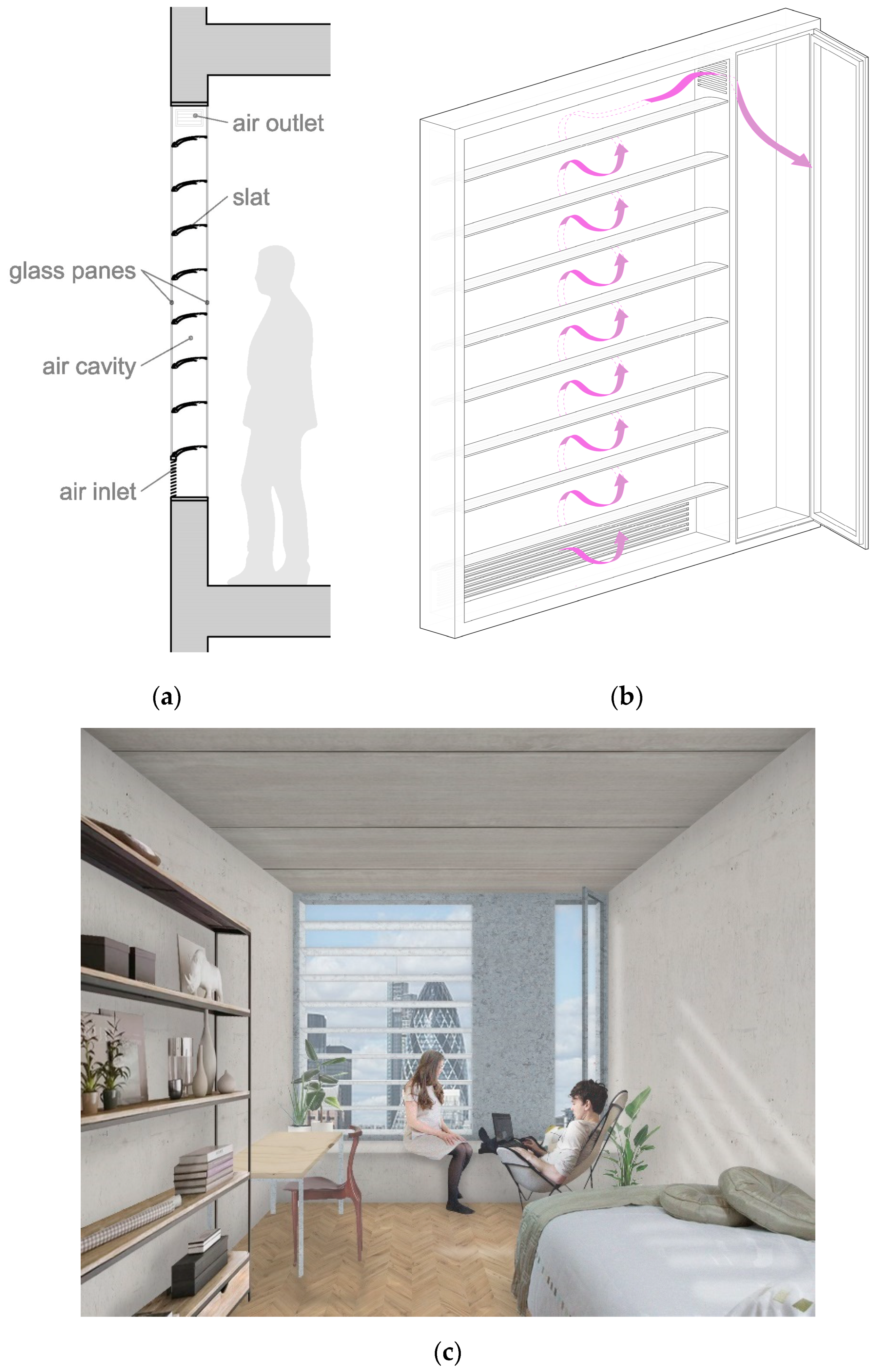
The slats are fitted between the two skins of glass (Figure 1a). The slats occupy the entire horizontal section of the cavity, forcing the air to pass through the interior of each slat. It is during the twisting circulation of the air—as it passes through and flows over the surface of the slats—that the air is purified using physical filtration and photocatalysis.
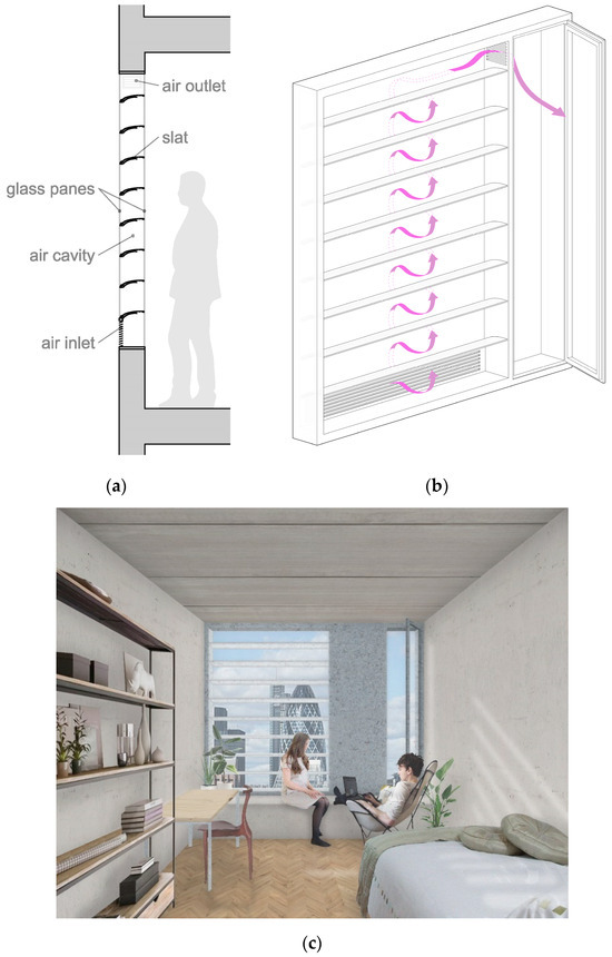
Figure 1.
(a) Cross section with the parts or the panel; (b) the panel with the air management zone and the purification zone; (c) the aspect of the component from indoor.
The façade’s double skin is divided so that ventilation air can be managed in compartmentalised zones (Figure 1b). One possible configuration would use vertical divisions to allow air to enter the purification zone through a low-level opening, circulating past the purifying slats and then controlling the entry of this air into the interior space through openings in a side panel (Figure 1c). Many other configurations would be possible, making this system useful for all kinds of façade designs.
2.3. The Slat
There are two different proposals for the slat’s design: the slat which contains physical filters, and the slat which filters. Both satisfy the same functions but do so through different means, adapting to the possibilities offered by each material and each manufacturing process involved.
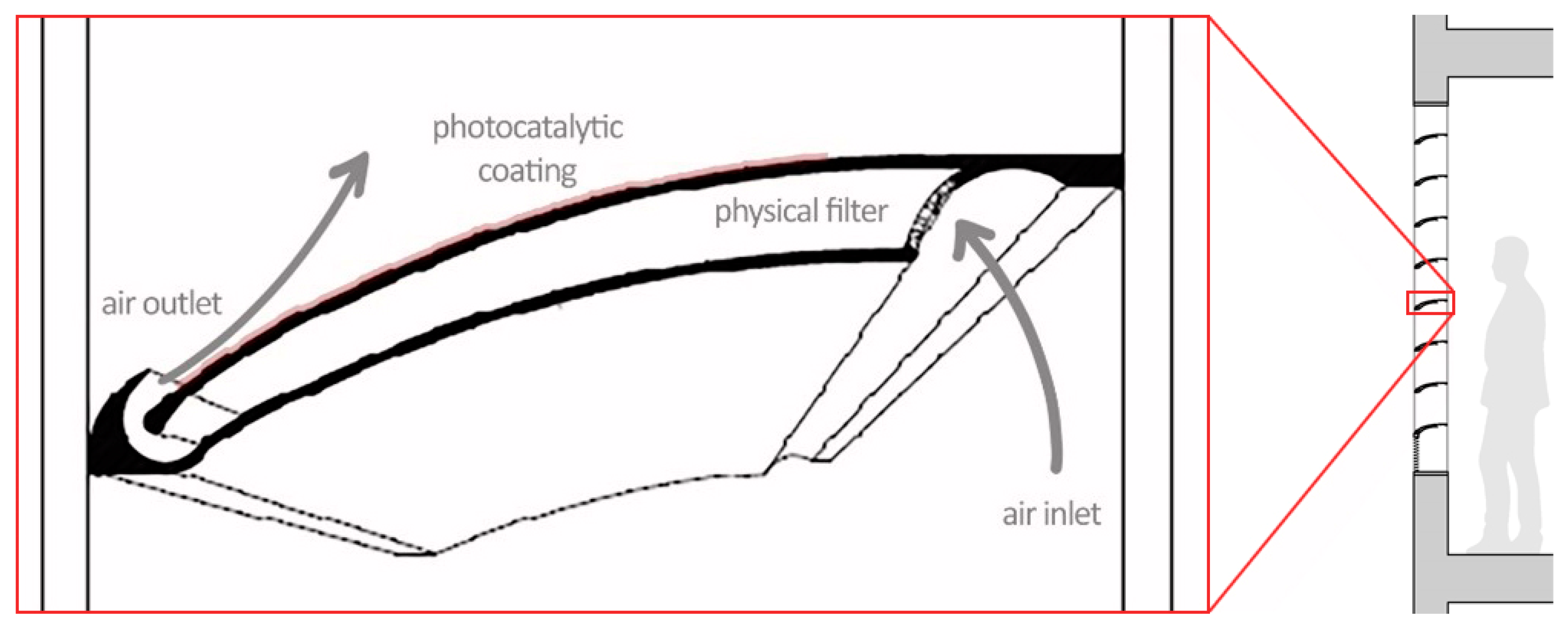
The slat which contains filters is based on an extruded profile covered by a photocatalytic material on the upper side of the external surface. The geometry of the slat frees up an internal cavity in which one or several physical filters can be fitted according to the requirements of the project (Figure 2), as well as enabling the air which has already flowed through the physical filter to then flow back across the exterior upper surface with the photocatalytic coating via the Coanda effect [26].
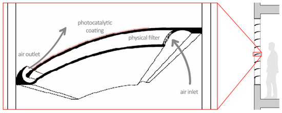
Figure 2.
Cross section of the slat which contains filters.
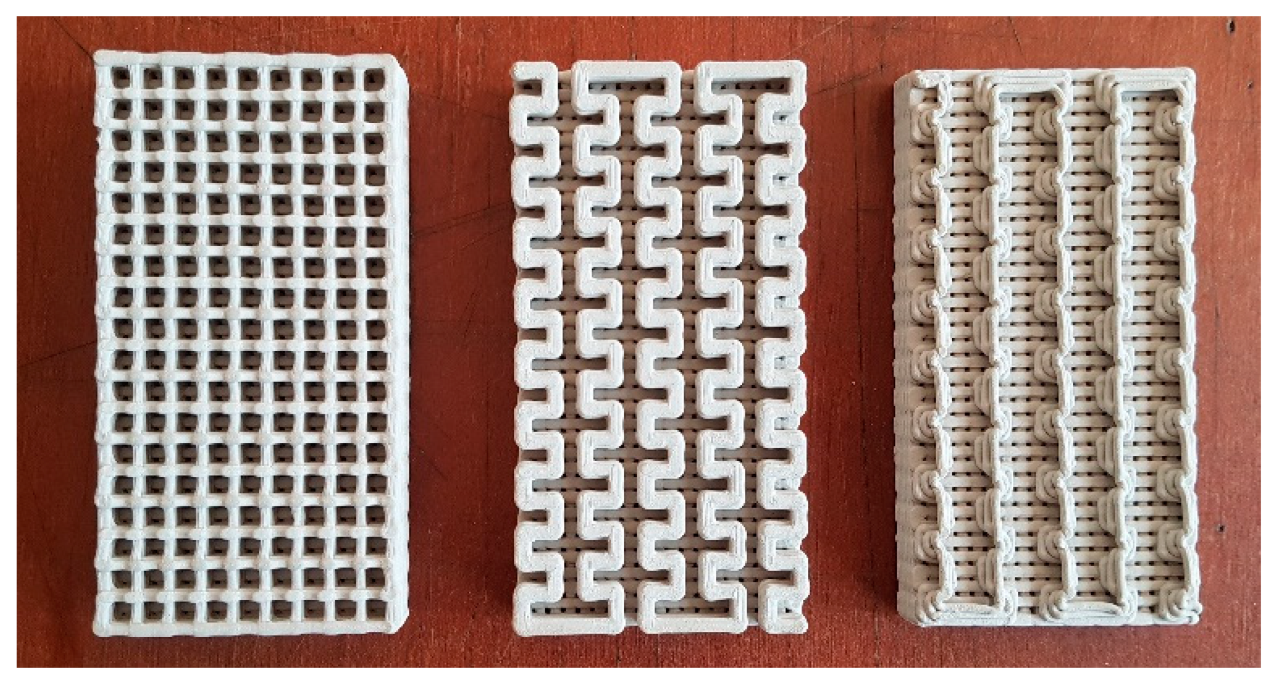
The filtering slat is a printed ceramic fretwork prism also coated in a photocatalytic material on the upper side (Figure 3). Printing clay permits obtaining a slat traversed by channels with a variable section. It goes from less than 1 mm on the backside, to the width needed to obtain the maximum sun-exposed surface on the sunny face, which is between 2 and 3 mm. The printed ceramic allows the slat design to be adapted to each location and façade orientation. The air crosses the prismatic monolith, depositing particles in suspension during the circulation flow by means of micro-channels on the rough-faced sides. The photocatalytic purification occurs when the air emerges through the upper face of the prism and comes into contact with the titanium dioxide coating. On this upper face, the increase in the capillary section size enables a greater exposure to the solar radiation required for the photocatalytic process [27].
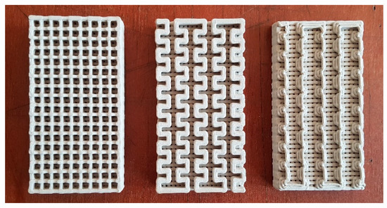
Figure 3.
Printed ceramic with different fretwork patterns.
The ceramic slats are not disposable filters but are cleaned by vacuuming and, therefore, do not generate waste. Consequently, the double-skin panel needs to be openable from the inside to permit the cleaning of the slats [28].
3. Component Functionality Tests
The adequacy of this element in the functioning of a natural ventilated building lies in its capacity to provide optimum performance in different aspects: ventilation, air purification, solar protection, and thermal performance. Although the novelty of the system lies in the air purification capacity of the slat, the other aspects are necessary to verify its applicability in buildings. To facilitate understanding, the text is structured so that each section contains the methodology used, the results, and the main findings of the studied aspect. These aspects were analysed using a theoretical façade unit measuring 1 m wide by 2 m high in a non-residential building in a Mediterranean climate zone, at a latitude of 41° N.
3.1. Building Ventilation
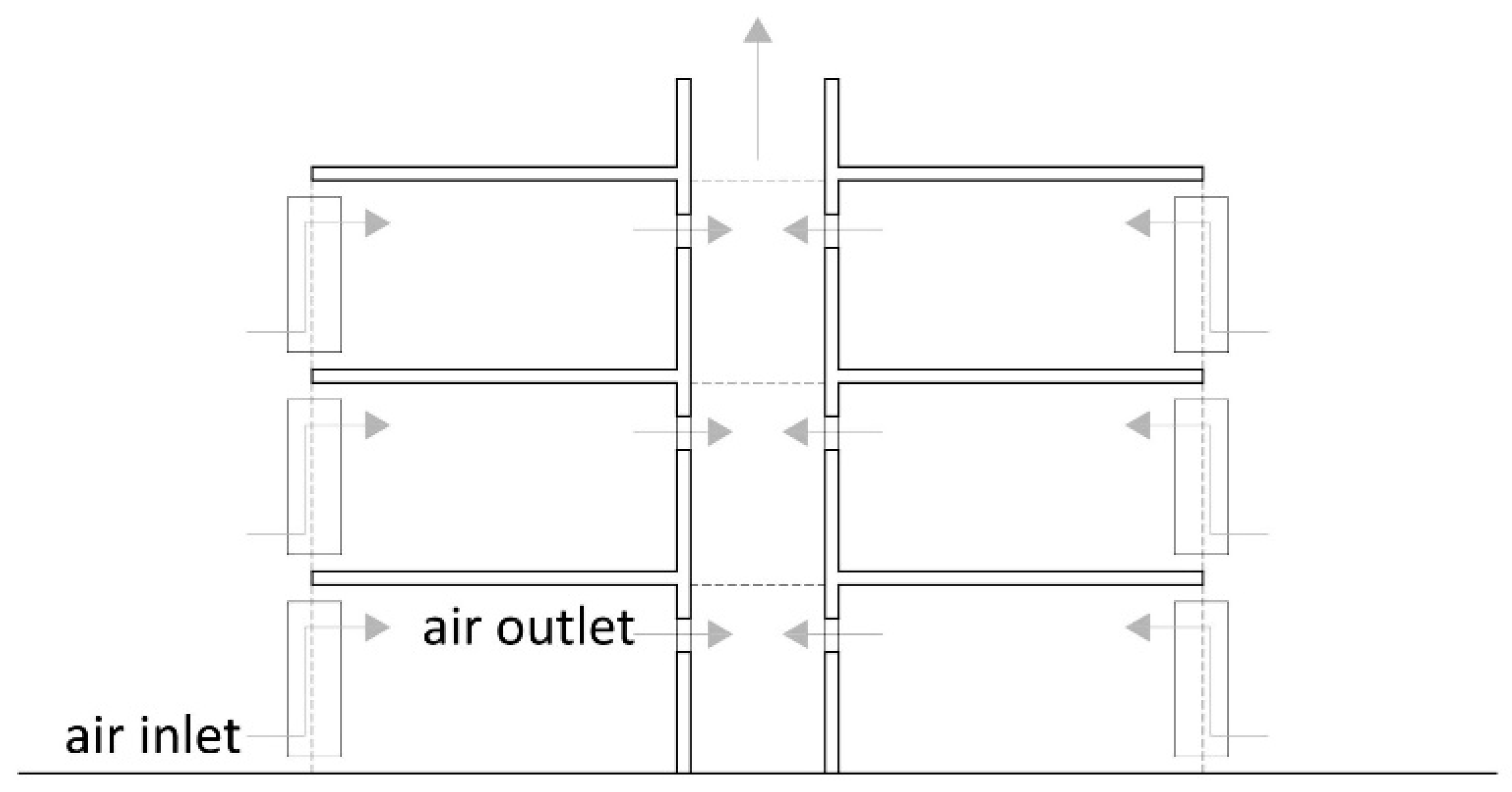
The first verification was how to integrate this component in a building with natural ventilation. In detail, the component has a low-level opening that provides the air intake with a lengthwise gap, the dimensions of which depend on the ventilation rate required indoors. Unlike conventional windows, which produce ventilation both in and out, the system works only in one direction, towards the interior. Once inside, the air crosses the space and must be extracted elsewhere: through another façade opening (cross ventilation) or towards a courtyard located inside the building. An example of a possible natural ventilation scheme at the building scale is shown in Figure 4. In this sketch, the air inlet is produced through each façade component, while the air outlet is produced on the opposite wall, connected to a ventilation shaft. The physical processes involved are not simple since many parameters influence air movement in buildings, especially in those which are naturally ventilated: leakage distribution in the building envelope, internal and external temperatures, wind velocity, and wind direction, to name a few [29]. The analysis of the component comprised the dimensional requirements to fulfil ventilation rates according to regulations.

Figure 4.
Scheme of a possible building ventilation strategy using an atrium with a draught-enhancing chimney.
International standards and local regulations establish ventilation rates in accordance with different building categories (ISO 17772-1:2017 [30], ISO 17772-2:2018 [31], EN 16798-1:2019 [32], CEN/TR 16798-2:2019 [33], ASHRAE 62.1:2016 [34], ASHRAE 62.2:2016 [35]), which can be obtained by different methods [36]. The Spanish regulation, Reglamento de las Instalaciones Térmicas de los Edificios (RITE) [37], uses similar methods. Regulatory standards classify air flow rates in categories according to the percentage of dissatisfied occupants (PD) in terms of IAQ. In the case of non-residential buildings, it applies Category II (ISO 17772, EN 16798, ASHRAE 62.1), or IDA2 (RITE) air flow rates.
The method used to calculate ventilation comes from the addition of the air flow rates needed to dilute emissions derived both from occupants qp (L/s·pers), and from the building component in non-residential zones qB (L/s·m2). In the first case, standards establish a difference according to occupants’ adaptation to odour from other people, with higher rates for the non-adapted. In the case of ventilation rates due to the building and the level of pollution produced indoors, a distinction is drawn between very low polluting zones, low polluting, and non-low polluting zones. RITE provides air flow rates depending on the occupation and surface area, but the use of rates per square metre is only possible for spaces without permanent occupation (Table 1).

Table 1.
Air flow rates in standards and building regulations in non-residential buildings.
Based on Table 1 values, the total ventilation rate (qtot) in a theoretical non-residential building is expressed in Equation (1), which calculates the net contribution of the occupants with the building component:
qtot = N · qp + A · qB
The value ascribed to occupants (qp) depends on the occupation ratio assigned. EN 16,798 establishes 10 m2/pers for office buildings (N), which has been used here for calculations. The most restrictive ventilation rates are 7 L/s·pers in international standards and 12.5 dm3/s·pers in the Spanish regulation, so the application of this ratio in an office building would result in 0.7 L/s·m2 and 1.25 L/s·m2, respectively. The contribution of floor area air flow rates (qB), in Category II and a non-low polluting environment, is 1.4 L/s·m2. When this value is added to the contribution of occupation, it results in qtot = 2.1 L/s·m2, the maximum value obtained in the worst conditions. This value is higher than the ventilation rate defined by the Spanish regulation, which does not include the building component value. In relation to the SARS-CoV-2 pandemic situation, some publications have made recommendations on ventilation rates to guarantee air changes in buildings. In Spain, a minimum air flow from the exterior of 12.5 dm3/s·pers was recommended [38], which is the same assigned to an IDA 2 category from RITE.
The ventilation ratio of 2.1 L/s·m2, along with an acceptable air speed (va) of 0.12 m/s (in order not to produce noise), results in an air cross section (Sv) of 0.0175 m2/m2 according to Equation (2). This means that each square metre of internal floor area needs 0.0175 m2 of air crossing area for ventilation, in the least optimal scenario.
qtot = Sv · va
Considering the façade unit defined at the beginning of this section (1 m wide), the gap needed to fulfil the ventilation requirements would be 1.75 cm high. The same calculation was made with the less restrictive scenario, resulting in a 0.5 cm gap height. In the case of the RITE, the calculated height was 1 cm. The studied scenarios show that a façade gap between 0.5 and 1.75 cm high and 1 m long would be enough to provide ventilation for one square metre of internal floor area (Table 2).
Table 2.
Dimension of the gap needed to ventilate one square metre of internal floor area in different scenarios.
The maximum height for the air gap in a panel was limited to 12 cm as a design requirement, sufficient to control noise, to guarantee the Coanda effect on the slats and to prevent foreign objects from entering the cavity. By proportion, a 12 × 100 cm gap would provide adequate ventilation for 6.85 m2 of internal floor area, with a 2.1 L/s·m2 required air flow. According to this, each façade component would provide ventilation to almost 7 square metres of internal floor area, comparable to the common area of an individual office. For spaces with lower ventilation requirements, the component could provide ventilation to even larger areas.
3.2. Air Purification
The next step was to determine the purification capacity of the slat, with specific attention paid to the photocatalytic activity of the coating. Usually, ventilation systems integrate filtering devices for particles, but none of them eliminate chemical compounds from the air. As explained in the introduction section, NO2 is one of the most common air pollutants indoors that can cause adverse effects on building occupants [39]. The major sources of this gas are internal combustion engines [40], and they are found in high concentrations in cities with heavy traffic. The significance of NO2 is highlighted by public administrations, which provide records of this gas’s concentrations in maps and graphs with continuous data [41,42]. The multi-purpose façade component proposes two air-cleaning strategies: filtering for physical particles, and photocatalysis for chemical compounds. The physical filtering is applied to PM2.5 and PM10 particles, while air depuration applies to NOx.
The effectiveness of filters is measured with the Minimum Efficiency Reporting Value (MERV) parameter. The scale ranges from 1 to 16, depending on the minimum particle size filtered. For PM2.5 and PM10 particles, it applies a 5–8 value or higher. ISO 16890 [43] characterises the filtration performance and divides filters into groups according to the retention of particles from 0.30 to 10 μm in size. For PM2.5 and PM10 particles, filters must achieve a minimum efficiency of 50% in ISO ePM2.5 and ePM10 groups. Filtering devices are difficult to include in openable windows because of their thickness and appearance, which partially block the vision to the outside. Thus, they are limited to close-woven materials that reduce the intake of all but the smallest particles [44]. The use of a slat allows the integration of the most effective filters, since they are located inside the element, out of sight. The design offers the possibility of integrating a series of filters with different degrees of effectiveness.
On the other hand, the elimination of chemical compounds is produced by photocatalysis, an oxidation chemical reaction in which the polluting elements are disintegrated. With this purpose, a photocatalyst element is applied as a coating on the exposed surface of the slat, which reacts with an oxidant compound, the oxygen (O2) present in the air and activated by UV solar radiation [45]. Titanium dioxide (TiO2) is the most common photocatalyst element used in this reaction. The design of the slat guarantees the contact of the air flow with the photocatalytic coating due to the Coanda effect, while the position of the element in relation to solar radiation ensures the activation of the chemical process [46]. There are several photocatalytic coatings on the market which can be applied using different processes. The most common ones are cold applications by immersion or spray and high-speed thermal projection. The coating is then applied to any support material, which can be any material used in solar protection slats, such as aluminium or ceramics.
The effectiveness of the photocatalytic capacity of three photocatalytic coatings was tested on five base materials. The support materials were extruded aluminium (AX), printed ceramic with one-side perforation (CI-1C), printed ceramic with perforation on both sides (CI-2C), extruded ceramic (CX), and foamed aluminium with a medium porosity (AE-M). The coating was applied to each 10 × 5 × 0.14 cm sample with PuretiTM paint (PUR), ProCleanTM paint (CLE) and thermal projection (PVC). The combination of support materials and coatings are shown in Table 3, each with a number and a code.
Table 3.
Samples used for testing with codes, material of support and coating applied.
The oxidation of Nitric Oxide (NO) was tested to determine the photocatalytic activity of each combined sample. The test was conducted in the Analysis and Photocatalytic Treatment of Pollutants in Air Unit (FOTOAir) of the Energy, Environmental and Technological Research Center (CIEMAT). The experiment was conducted on 10 × 5 × 0,14 cm samples, following the ISO 22197-1 [47] indications and operation conditions for each phase of the study of photocatalytic activity (Table 4). The samples were washed with water and were dried for 24 h, before introducing them into the reactor. They were then pre-treated with UV-A radiation, according to the criteria established in the ISO 22197-1 [47] standard. The results obtained show data about NOx (NO + NO2), which correspond to the NO removed and NO2 formed during the experiment, expressed in percentage (%) and micromole (µmol) (Table 5).
Table 4.
Description of the test procedure according to ISO 22197-1.
Table 5.
Results of the laboratory tests in each sample: conversion percentage of NO and NOx (XNO-XNOx), quantity of NO and NOx degradation in µmol (NOe-NOxe), quantity of NO2 formed in µmol (NO2).
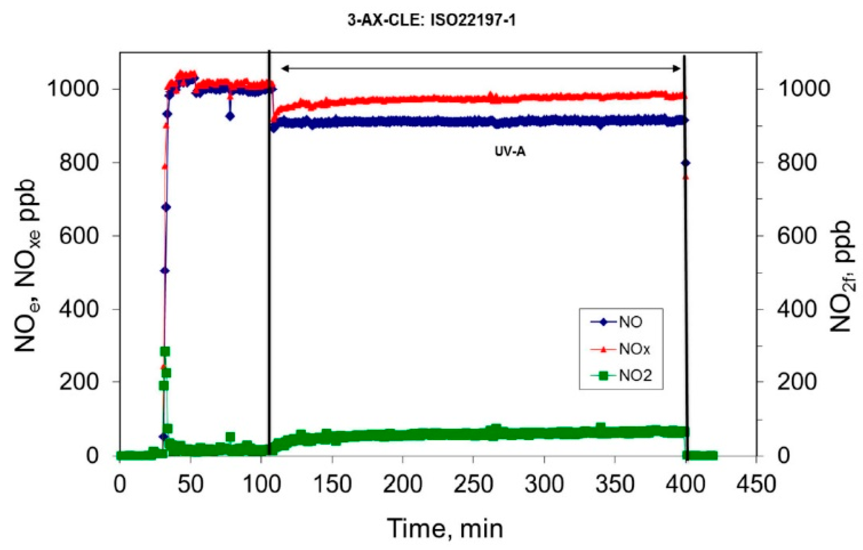
The results show that the best performance was obtained with sample 3, extruded aluminium with a ProClean™ paint coating. The percentages of chemical conversion of NO and NOx obtained were 9% and 5%, respectively. Figure 5 shows the conversion rate during the test. In Phase 4, under UV-A radiation, there is a noticeable drop in the NO and NOx components, together with an increase in the amount of NO2. The other samples showed less activity, with percentages ranging from 2 to 5% of NO degradation, and from 1 to 3% conversion of NOx. The results on the printed ceramics were lower than 5%, though the air flow in a real environment would favour absorption and diffusion and, therefore, could imply an improvement in the photocatalytic process.
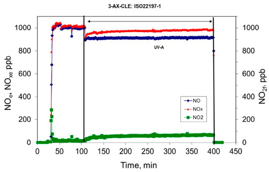
Figure 5.
Conversion of NO and NOx obtained for sample AX-CLE, based on [47].
The results obtained show the effectiveness of the photocatalytic reaction on the samples coated outside the laboratory. The application of the TiO2 to the samples was produced without strict control of the thickness and the amount of coating deposited, which could present slight variations. Considering this, a thicker application of photocatalytic coating could yield better results in terms of NO degradation. Apart from this, the results show the reaction on a single surface corresponding to one slat. If the effect was cumulative, a combination of five slats in the façade unit would suppose a higher NO degradation, provided that the conditions were optimal. This procedure would require a fluid-dynamic model to test the precise effect in the whole component.
3.3. Solar Protection
The slats contained in the façade component manage solar radiation like a conventional louver in a Mediterranean climate. But at the same time, the photocatalytic coating requires access to solar radiation to activate the chemical reaction, which will be most effective with high irradiation. Thus, the component has a twofold function: protecting the interior of the building from overheating and guaranteeing solar access to the upper part of the slats. Other aesthetic requirements of the component are keeping the appearance of a louver, with a reasonable distribution of slats, and allowing a view of the outside. The optimal distribution and geometrical design of a façade component was determined with these requirements in mind.
The calculation settings were defined according to the dimensional conditions of the façade component. The width of the air chamber was fixed at 20 cm, with a length of 100 cm. The total component’s vertical dimension is 200 cm, which accommodates a distribution of slats 6 cm thick. The geographical position of the façade component was fixed at latitude 41° N. With the aim of receiving maximum solar radiation on the coating, the component was oriented towards the south, the optimal orientation in the northern hemisphere. The geometrical analysis sought two parameters, the optimal spacing between slats, and their angle of tilt.
The geometric spacing between slats depends on the sun’s position during certain periods of the year, and the depth of the slat (Figure 6a). The height of the sun on the summer solstice fixes the maximum separation between slats which, at 41° N latitude, results in 61.55 cm (from the lower side of one slat to the upper side of the next slat). At the opposite extreme, the minimum spacing that guarantees the upper surface of the slats are exposed to the sun all year is 9.3 cm, which corresponds to the position of the sun on the winter solstice. The 61.55 cm spacing would imply only three slats per module and was therefore discarded. Taking into consideration the separation defined by the sun’s position in the equinox, the sun would reach inside the building three months before and after the day of the winter solstice (October-March), as shown in the stereographic solar diagram (Figure 6b). In this case, the spacing would be 22.6 cm. This separation creates a rhythm of blocked and open vision in the ratio 1:3.7 (6 and 22.6 cm) that assimilates the appearance of a louver module; with this spacing, the module could incorporate six slats arranged in a 2 m high cavity.
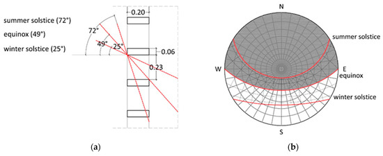
Figure 6.
(a) Section with solar altitude on the winter solstice, summer solstice, and equinox at latitude 41° N; (b) solar obstruction of the slats in the stereographic solar diagram.
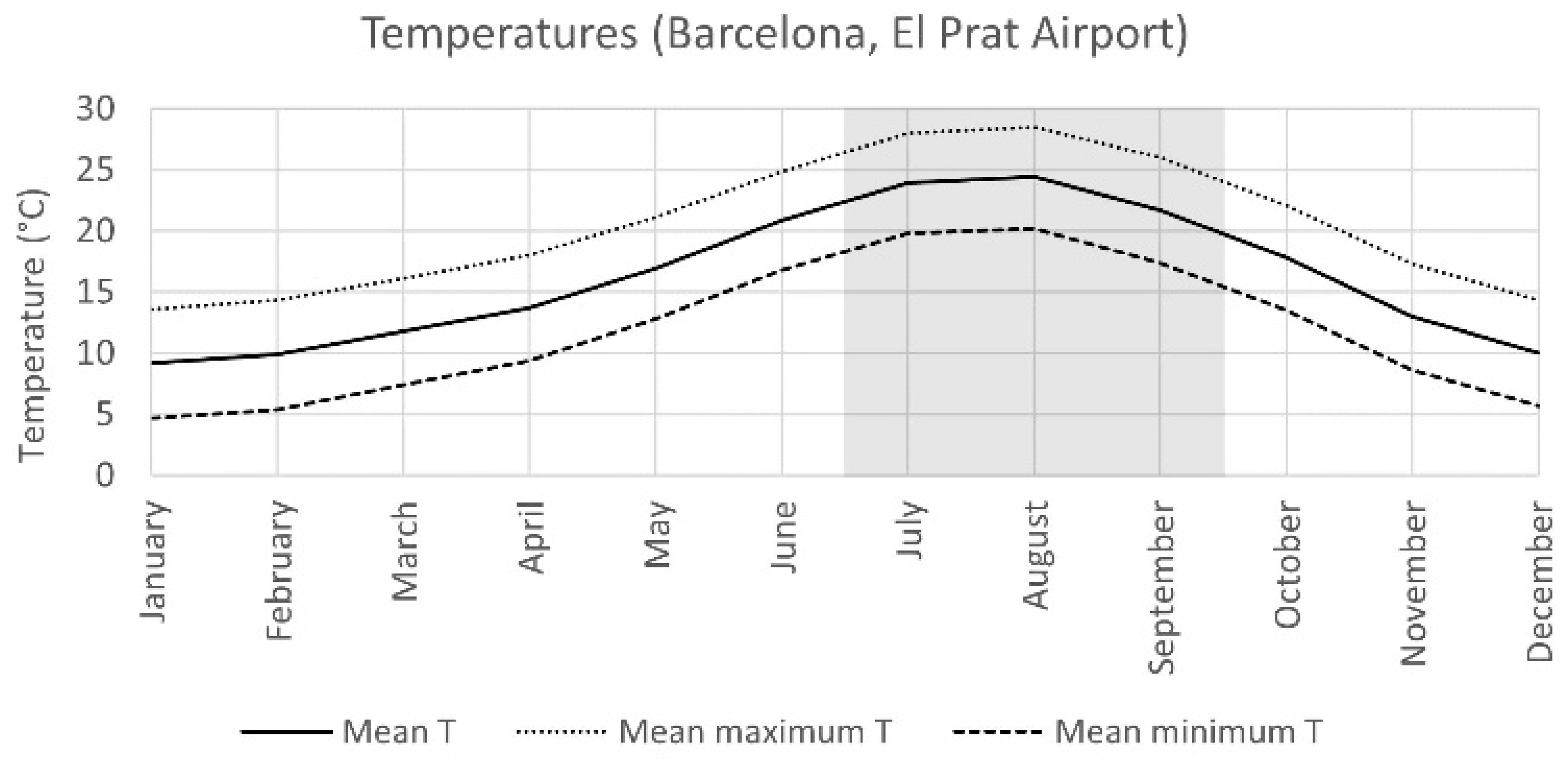
Considering the climate data for Barcelona, a city located at 41°N latitude with a Mediterranean climate, it may be seen that the mean temperatures from June to September are above 20–21 °C (Figure 7). This is the same period when the slats protect the building interior from direct solar radiation, and this shade helps to avoid overheating during the warmest months. Apart from this, the annual number of hours of sun in the Mediterranean climate zone is high (in Barcelona it exceeds 2315), which guarantees optimal radiant conditions for activating the photocatalytic process.

Figure 7.
Temperatures at Barcelona airport: mean, mean maximum, and mean minimum (Source: AEMET). In grey, the period with total shading of the interior.
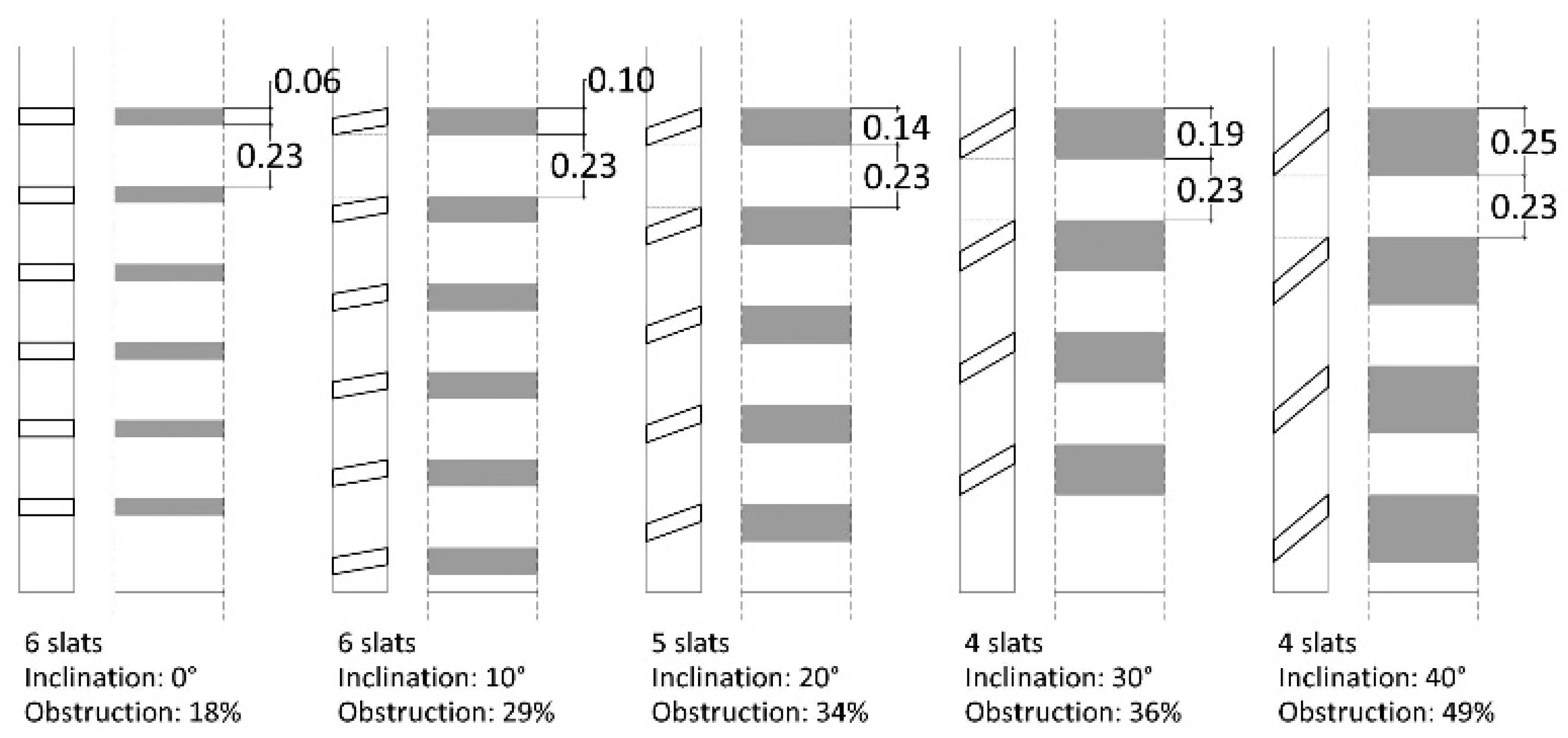
The second parameter is the tilt angle. The slat inclination is obtained with two premises: obstructing no more than 50% of the outside view and providing the maximum solar irradiation on the surface of the slat. The calculation was made with 22,6 cm free distance between slats. Five basic inclinations were calculated, 0°, 10°, 20°, 30° and 40°. In each case, the percentage of visual obstruction was graphically calculated, resulting in 18%, 29%, 34%, 36% and 49%, respectively (Figure 8). Considering the latitude and orientation in this case, the maximum value of irradiation corresponds to a 35° inclined surface. At this point, the need for maximum radiation must be considered together with the geometric factors related to sunlight and vision from outside. According to that, 20° and 30° inclined slats fit with this requirement, since a higher slant (40°) would block most of the vision outside. Taking into consideration the distribution of the slats in the panel, a higher tilt angle means more separation between slats, and therefore less elements in the same panel unit. Consequently, the solution that fits best in this situation is a distribution of five slats inclined 20° with 22.6 cm spacing between them.
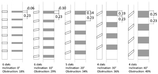
Figure 8.
Slats’ arrangement with 0°, 10°, 20°, 30° and 40° inclination.
3.4. Thermal Behaviour
The repercussions on indoor thermal comfort of this component depend on if it is open, allowing ventilation, or closed. When closed, the heat exchanges between the inside and outside depend on the heat transfer coefficient, the U-value of the double-skin façade and the solar energy transmittance of the component. Both values can vary depending on the characteristics of the glass panes that configure both sides of the component. In the case of the total solar energy transmittance, this value can change by a factor greater than five according to some studies [48].
However, the main concern in this case is the temperature of the incoming air after sweeping over the surface of the slats. When the air crosses the double-glazed cavity, its temperature is expected to increase because of the greenhouse effect and the heat transfer between the slats and the air. This rise in the temperature of the air crossing the cavity and the surface temperature of the glass panes is difficult to determine [49]. One of the difficulties is that the absorptivity and emissivity of photocatalytic coatings is not available in datasheets. In a previous experiment conducted with ceramic samples and a ProClean-Air photocatalytic coating, we could determine the long-wave emissivity of the coating. It turned out to be 0.59 on average with an uncertainty of 0.13 [50].
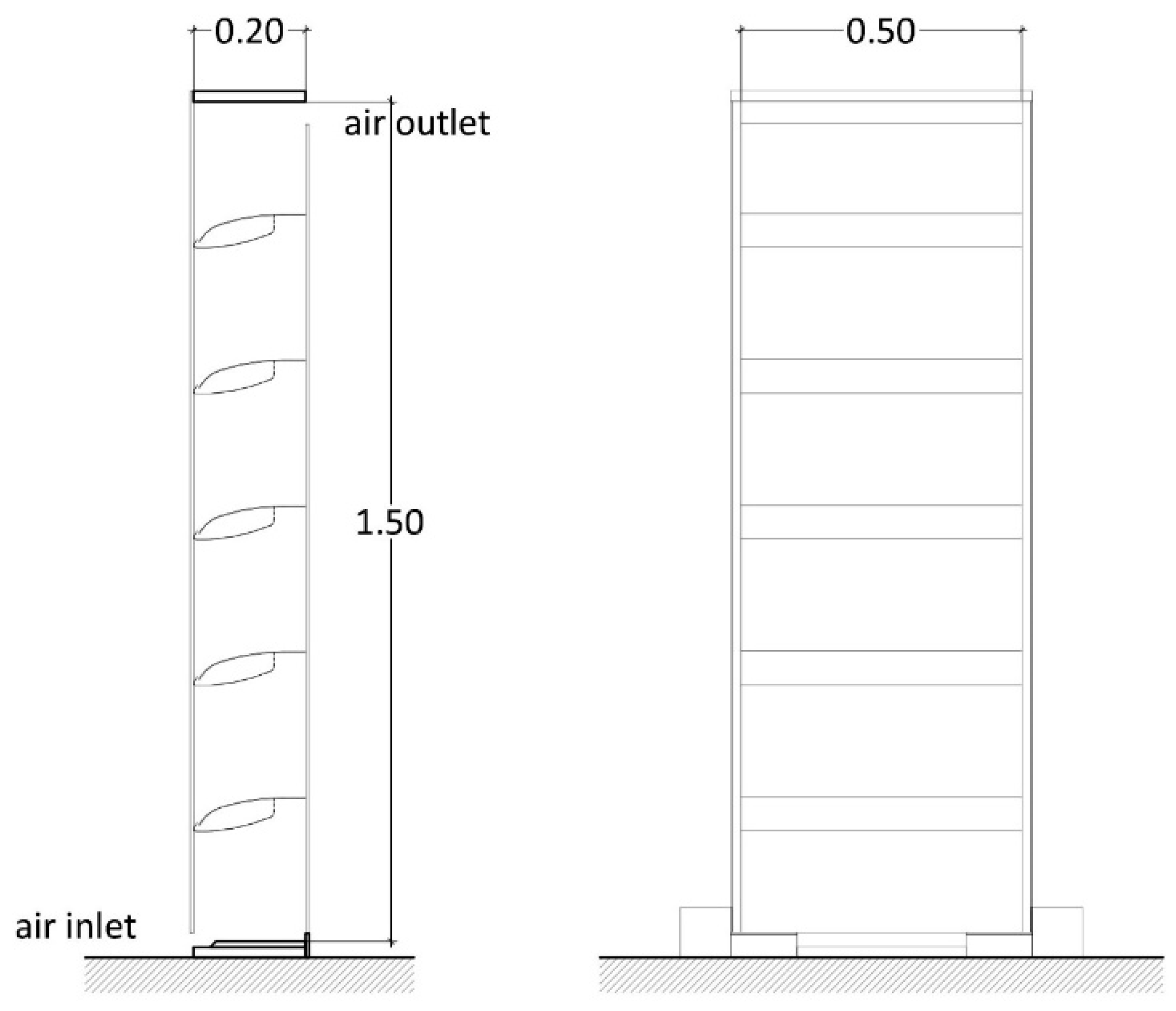
To determine the order of magnitude of the increase in temperature, we installed a mock-up of the university terrace in the summer of 2019 and carried out a series of temperature measurements [50]. It was used as an experimental preliminary study of the component thermal behaviour and to validate a further CFD simulation of the component. The mock-up was built with wooden and cardboard slats (manually painted with a photocatalytic ProCleanTM paint), wooden structure, and single glass on both sides, and was oriented towards the south. The dimensions are shown in Figure 9. As proof of concept, some preliminary measurements were also taken using a MQ-2 gas sensor and an Arduino board connected to a computer. These measurements indicated a decrease of around 15% on the pollution products sensed by the MQ-2 in the air passing through the mock-up. As for the temperature measurements, they were taken in warm and cold periods and showed an average increase in air temperature of about 6–10 °C between the air on the lower inlet and the air on the upper outlet [50].

Figure 9.
Dimensions of the mock-up used for preliminary temperature measurements.
In parallel, a rough calculation of the single component thermal balance was made to determine the increase in temperature of the air in the cavity. The calculation considers that at a given time, the gains for solar radiation and the losses caused by ventilation and heat transfer are equal, as the thermal mass is low. The parameters considered in heat losses were the surface that encloses the cavity with its corresponding U-value (glass and wood), air flow (Q), air density (δ) and air specific heat (Ce). The parameters considered in heat gains were solar irradiation in a vertical plan on the 4th of October at 12:00 ST (midday near Equinox) (Rv) at the latitude 41° N, exposed glass surface (S), light transmission of the glass (t), and light absorption of the elements inside the cavity (α) (Table 6). Applying Equation (3), the increase in the temperature of the air in the cavity resulted in almost 10 °C. This value is in concordance with what was measured in the mock-up.
(Sg · Ug + Sw · Uw) · ∆T + (Qa · ∂a · Cea) · ∆T = Rv · Sg · t ·α
Table 6.
Parameters considered in Equation (3).
The preheating of the air for ventilation provides the possibility of using the component as a passive heating element, depending on the relation between local temperatures and the temperature rise produced in the cavity. These results illustrate the possible increase in temperature in a similar situation and suppose a starting point for further analysis, since the mock-up was installed in an isolated open space. In this line, we conducted a simulation in different climates and concluded that the geographical areas where we could take advantage of the full potential of filtering and passive preheating would be in temperate or cold areas with many hours of solar radiation [50]. These areas could be central Europe and low latitude areas at a high altitude above sea level. On the other hand, the heat released to the interior through the ventilation air can be a problem in hot or temperate climates with a warm season, making it necessary to conduct more simulations to determine its suitability in these climates.
4. Conclusions
The analysis and tests carried out expound the potential of the multi-purpose façade element as well as its suitability for integration in non-residential buildings. With respect to ventilation, the study shows the suitability of the component to fulfil the required ventilation rates in non-residential buildings. Thus, a 1-metre-long component with a 12 cm height gap would be adequate to ventilate an office of 7 m2 area, which means that a 28 m2 classroom or office would need four components. The façade component is likely to provide noise reduction from the outside as with any double-skin façade or double window. Considering the overall ventilation of the building, a sufficient depressurisation to create the suction will always be required, which can be obtained by natural means or using a mechanical device or a hybrid system.
The results on air cleaning obtained in the laboratory show that, in specific samples, the reduction in air pollutants can reach 9% of NO and NOx degradation. Further studies are needed to confirm an improvement when the coating is applied under manufacturing conditions. The component has two advantages with respect to other ventilation filtering devices. First, the double cleaning devices are integrated within the façade element. Therefore, the window itself contains the physical and photocatalytic cleaning system, which can be cleaned or replaced. Second, the presence of filters in the component does not compromise vision to the outside, unlike windows with woven materials that cover the entire opening surface.
As the component is designed as a louver, it provides solar protection during certain periods of the year, but without covering the upper surface of the slats that need solar radiation to activate the photocatalytic activity. The position and dimension of the slats at a 41° N latitude show that a 22 cm spacing between them with a tilt angle of 20° provide the best solution. This analysis can be extrapolated to other latitudes according to the corresponding solar diagram and climate data, always seeking a compromise between solar protection and exposition.
Location and climate also determine the thermal behaviour of this component concerning the conditions inside the building. It is essential to predict the temperature reached by the air inside the cavity for future applications of the façade component. This will determine which climates, seasons, and times of day will be best for natural ventilation. From the results obtained so far, it is expected that the component fits best in temperate climates with mild temperatures in summer and the mid-season. Considering a rise in temperature of about 10 °C relative to the outside air temperature, a location with temperatures of about 12 °C during the day could take advantage of this preheated air, if there is sufficient solar irradiation. On the contrary, on hot days this preheating of the ventilation air is not desired. The system is not appropriate in hot climates.
All these approaches show the potential of the façade component for non-residential buildings. The solution suits polluted environments and buildings where the control of thermal conditions by users is important; for example, hotel rooms, residences, schools or offices. Considering that today most façades are conceived as barriers more than filters, this façade component provides a sensitive contact with the outside, which fits in the context of COVID-19 requirements. It has health and wellbeing benefits for building’s users, since contact with fresh air according to their needs contributes to improving the perception of the internal environment with clean air free of pollutants. Multi-purpose components within the building fabric offer the opportunity of developing complex elements by relating the needs of users and the possibilities of technology. The multi-purpose façade component studied is an example of this.
5. Patents
A patent and a utility model were registered related to this project [51,52].
Author Contributions
Conceptualisation, J.L.-B., C.P., A.I. and O.R.; methodology, J.L.-B., C.P., A.I. and O.R.; formal analysis, J.L.-B., C.P., A.I. and O.R.; investigation, J.L.-B., C.P., A.I. and O.R.; resources, J.L.-B., C.P., A.I. and O.R.; data curation, J.L.-B., C.P., A.I. and O.R.; writing—original draft preparation, J.L.-B., C.P.; writing—review and editing, J.L.-B., C.P., A.I. and O.R.; visualisation, J.L.-B., C.P. and O.R.; supervision, J.L.-B., C.P., A.I. and O.R.; project administration, J.L.-B., C.P.; funding acquisition, J.L.-B., C.P. All authors have read and agreed to the published version of the manuscript.
Funding
This work was supported by the Agency for Management of University and Research Grants (AGAUR), the European Regional Development Fund (ERDF), under grant 2018-LLAV 00011, LLAVOR-IMPULSA program.
Data Availability Statement
No new data were created or analyzed in this study. Data sharing is not applicable to this article.
Acknowledgments
We acknowledge the collaboration of the Analysis and Photocatalytic Treatment of Pollutants in Air Unit (FOTOAir) in the Energy, Environmental and Technological Research Center (CIEMAT); the Thermal Spray Center from Universitat de Barcelona; Ariño Douglass; ProCleanTM and PuretiTM paints. We also acknowledge the mentoring of Hydro and Naturgy in this project.
Conflicts of Interest
The authors declare no conflicts of interest. The funders had no role in the design of the study; in the collection, analyses, or interpretation of data; in the writing of the manuscript; or in the decision to publish the results.
References
- OHCHR. The Right to Adequate Housing; Fact Sheet No. 21/Rev. 1; Office of the United Nations High Commissioner for Human Rights: Geneva, Switzerland, 2014; Available online: https://unhabitat.org/sites/default/files/download-manager-files/Right%20to%20adequate%20housing.pdf (accessed on 28 October 2021).
- COAC. Espais Interiors Saludables; Col·legi Oficial d’Arquitectes de Catalunya: Barcelona, Spain, 2020; Available online: www.arquitectes.cat/ca/guia-espais-saludables (accessed on 28 October 2021).
- ILFI. Health & Happiness Petal Intent: Living Building Challenge; International Living Future Institute: Seattle, WA, USA, 2021; Available online: https://www.manula.com/manuals/living-future/living-building-challenge-4-1/1/en/topic/i10-intent-requirements (accessed on 28 October 2021).
- Ortiz, M.; Itard, L.; Bluyssen, P.M. Indoor environmental quality related risk factors with energy-efficient retrofitting of housing: A literature review. Energy Build. 2020, 221, 110102. [Google Scholar] [CrossRef]
- Burge, S.; Hedge, A.; Wilson, S.; Bass, J.H.; Robertson, A. Sick building syndrome: A study of 4373 office workers. Ann. Occup. Hyg. 1987, 31, 493–504. [Google Scholar] [CrossRef] [PubMed]
- Rostron, J. Sick building syndrome: A review of causes, consequences and remedies. J. Retail Leis. Prop. 2008, 7, 291–303. [Google Scholar] [CrossRef]
- Jaakkola, J.J.K.; Miettinen, P. Type of Ventilation System in Office Buildings and Sick Building Syndrome. Am. J. Epidemiol. 1995, 141, 755–765. [Google Scholar] [CrossRef] [PubMed]
- Luna-Navarro, A.; Loonen, R.; Juaristi, M.; Monge-Barrio, A.; Attia, S.; Overend, M. Occupant-Facade interaction: A review and classification scheme. Build. Environ. 2020, 177, 106880. [Google Scholar] [CrossRef]
- WHO. Public Health and Environment; World Health Organisation: Geneva, Switzerland, 2021; Available online: https://www.who.int/data/gho/data/themes/public-health-and-environment (accessed on 28 October 2021).
- WHO. Ambient (Outdoor) Air Pollution; World Health Organisation: Geneva, Switzerland, 2021; Available online: https://www.who.int/en/news-room/fact-sheets/detail/ambient-(outdoor)-air-quality-and-health (accessed on 28 October 2021).
- EEA. Air Quality in Europe: 2019 Report; European Environment Agency: Copenhagen, Denmark, 2019. [CrossRef]
- CEN. Guideline for Using Indoor Environmental Input Parameters for the Design and Assessment of Energy Performance of Buildings; CEN TC 156. WG 19-N89. Draft 8 EN/TR 16798-2 WD; Comité Européen de Normalisation: Brussels, Belgium, 2002. [Google Scholar]
- Brager, G.S.; Paliaga, G.; de Dear, R. Operable Windows, Personal Control, and Occupant Comfort. ASHRAE Trans. 2004, 110, 17–35. Available online: https://escholarship.org/uc/item/4x57v1pf (accessed on 5 August 2024).
- Luo, M.; Cao, B.; Ji, W.; Ouyang, Q.; Lin, B.; Zhu, Y. The Underlying Linkage between Personal Control and Thermal Comfort: Psychological or Physical Effects? Energy Build. 2016, 111, 56–63. [Google Scholar] [CrossRef]
- Santamouris, M.; Wouters, P. (Eds.) Building Ventilation: The State of the Art; Earthscan: London, UK, 2006. [Google Scholar]
- GhaffarianHoseini, A.; Berardi, U.; Tookey, J.; Li, D.H.W.; Kariminia, S. Exploring the advantages and challenges of double-skin facądes (DSFs). Renew. Sustain. Energy Rev. 2016, 60, 1052–1065. [Google Scholar] [CrossRef]
- Pomponi, F.; Piroozfar, P.A.E.; Southall, R.; Ashton, P.; Farr, E.R.P. Energy performance of Double-Skin Façades in temperate climates: A systematic review and meta-analysis. Renew. Sustain. Energy Rev. 2016, 54, 1525–1536. [Google Scholar] [CrossRef]
- Barbosa, S.; Ip, K. Perspectives of double skin façades for naturally ventilated buildings: A review. Renew. Sustain. Energy Rev. 2014, 40, 1019–1029. [Google Scholar] [CrossRef]
- Peng, J.; Curcija, D.C.; Lu, L.; Selkowitz, S.E.; Yang, H.; Zhang, W. Numerical investigation of the energy saving potential of a semi-transparent photovoltaic double-skin façade in a cool-summer Mediterranean climate. Appl. Energy 2016, 165, 345–356. [Google Scholar] [CrossRef]
- Lee, C.-S.; Lee, H.; Choi, M.; Yoon, J. Design optimization and experimental evaluation of photovoltaic double skin façade. Energy Build. 2019, 202, 109314. [Google Scholar] [CrossRef]
- Eom, Y.S.; Kang, D.H.; Choi, D.H. Numerical analysis of PM2.5 particle collection efficiency on an electrostatic precipitator integrated with double skin façade in a residential home. Build. Environ. 2019, 162, 106245. [Google Scholar] [CrossRef]
- Stec, W.J.; van Paassen, A.H.C.; Maziarz, A. Modelling the double skin façade with plants. Energy Build. 2005, 37, 419–427. [Google Scholar] [CrossRef]
- Flores Lazo, J. Integración en Fachada de Mecanismos de Depuración de Aire. Master’s Thesis, Polytechnic University of Catalonia, Barcelona, Spain, 2019, (unpublished). [Google Scholar]
- Knaack, U.; Klein, T.; Bilow, M.; Auer, T. Façades: Principles of Construction, 2nd ed.; Birkhäuser: Boston, MA, USA, 2014. [Google Scholar]
- Prieto, A.; Klein, T.; Knaack, U.; Auer, T. Main perceived barriers for the development of building service integrated facades: Results from an exploratory expert survey. J. Build. Eng. 2017, 13, 96–106. [Google Scholar] [CrossRef]
- Panitz, T.; Wasan, D.T. Flow attachment to solid surfaces: The Coanda effect. AIChE J. 1972, 18, 51–57. [Google Scholar] [CrossRef]
- Aguilar, P.; Borunda, L.; Pardal, C. Additive manufacturing of variable-density ceramics, photocatalytic and filtering slats. In Anthropologic: Architecture and Fabrication in the Cognitive Age, Proceedings of the 38th eCAADe Conference, Berlin, Germany, 16–17 September 2020; Technical University of Berlin: Berlin, Germany, 2020; Volume 1, pp. 97–106. Available online: https://cumincad.scix.net/cgi-bin/works/Show?ecaade2020_484 (accessed on 29 October 2021).
- Aguilar, P. Impresión 3D Cerámica de Densidad Variable Controlada. Ph.D. Dissertation, UPC, Architectural Technology Department, Barcelona, Spain, 2024. [Google Scholar] [CrossRef]
- Allard, F.; Santamouris, M. (Eds.) Natural Ventilation in Buildings: A Design Handbook; James & James: London, UK, 1998. [Google Scholar]
- ISO 17772-1:2017; Energy Performance of Buildings—Indoor Environmental Quality. Part 1: Indoor Environmental Input Parameters for the Design and Assessment of Energy Performance of Buildings. International Organization for Standardization: Geneva, Switzerland, 2017.
- ISO/TR 17772-2:2018; Energy Performance of Buildings—Overall Energy Performance Assessment Procedures. Part 2: Guideline for Using Indoor Environmental Input Parameters for the Design and Assessment of Energy Performance of Buildings. International Organization for Standardization: Geneva, Switzerland, 2018.
- BS EN 16798-1:2019; Energy Performance of Buildings. Ventilation for Buildings. Part 1: Indoor Environmental Input Parameters for Design and Assessment of Energy Performance of Buildings Addressing Indoor Air Quality, Thermal Environment, Lighting and Acoustics. British Standards Institution: London, UK, 2019.
- CEN/TR 16798-2: 2019; Energy Performance of Buildings. Ventilation for Buildings. Part 2: Interpretation of the Requirements in EN 16798-1—Indoor Environmental Input Parameters for Design and Assessment of Energy Performance of Buildings Addressing Indoor Air Quality. Comité Européen de Normalisation: Brussels, Belgium, 2019.
- ASHRAE Standard 62.1-2016. Ventilation for Acceptable Indoor Air Quality; American Society of Heating, Refrigerating and Air-Conditioning Engineers: Washington, DC, USA, 2016. [Google Scholar]
- ASHRAE Standard 62.2-2010. Ventilation for Acceptable Indoor Quality in Low Rise Residential Buildings; American Society of Heating, Refrigerating and Air-Conditioning Engineers: Washington, DC, USA, 2010. [Google Scholar]
- Khovalyg, D.; Kazanci, O.B.; Halvorsen, H.; Gundlach, I.; Bahnfleth, W.P.; Toftum, J.; Olesen, B.W. Critical review of standards for indoor thermal environment and air quality. Energy Build. 2020, 213, 109819. [Google Scholar] [CrossRef]
- España Ministerio de la Presidencia. Real Decreto 1027/2007, de 20 de julio, por el que se aprueba el Reglamento de instalaciones Térmicas en los Edificios. In Boletín Oficial del Estado; n. 207, 29/08/2007; MPR: Madrid, Spain, 2007; pp. 35931–35984. Available online: https://www.boe.es/boe/dias/2007/08/29/pdfs/A35931-35984.pdf (accessed on 28 October 2021).
- IDAE. Recomendaciones de Operación y Mantenimiento de los Sistemas de Climatización y Ventilación de Edificios y Locales para la Prevención de la Propagación del SARS-CoV-2; Gobierno de España. Ministerio de Sanidad: Madrid, Spain; Ministerio para la Transición Ecológica y el Reto Demográfico: Madrid, Spain; Instituto para la Diversificación y Ahorro de la Energía: Madrid, Spain, 2020; Available online: https://www.mscbs.gob.es/profesionales/saludPublica/ccayes/alertasActual/nCov/documentos/Recomendaciones_de_operacion_y_mantenimiento.pdf (accessed on 28 October 2021).
- Salonen, H.; Salthammer, T.; Morawska, L. Human exposure to NO2 in school and office indoor environments. Environ. Int. 2019, 130, 104887. [Google Scholar] [CrossRef]
- Alberts, W.M. Indoor air pollution: NO, NO2, CO, and CO2. J. Allergy Clin. Immunol. 1994, 94, 289–295. [Google Scholar] [CrossRef] [PubMed]
- Ministerio para la Transición Ecológica y el Reto Demográfico. Mapa de Calidad del Aire. 2024. Available online: https://sig.miteco.gob.es/calidad-aire/ (accessed on 7 August 2024).
- Generalitat de Catalunya. Qualitat de l’aire Actual; Medi Ambient i Sostenibilitat: Barcelona, Spain, 2024; Available online: https://mediambient.gencat.cat/ca/05_ambits_dactuacio/atmosfera/qualitat_de_laire/vols-saber-que-respires/ (accessed on 7 August 2024).
- ISO 16890-1:2016; Air Filters for General Ventilation—Part 1: Technical Specifications, Requirements and Classification System Based Upon Particulate Matter Efficiency (ePM). International Organization for Standardization: Geneva, Switzerland, 2016.
- Kang, K.; Kim, T.; Shin, C.W.; Kim, K.; Kim, J.; Lee, Y.G. Filtration efficiency and ventilation performance of window screen filters. Build. Environ. 2020, 178, 106878. [Google Scholar] [CrossRef]
- Boyjoo, Y.; Sun, H.; Liu, J.; Pareek, V.K.; Wang, S. A review on photocatalysis for air treatment: From catalyst development to reactor design. Chem. Eng. J. 2017, 310, 537–559. [Google Scholar] [CrossRef]
- Maness, P.-C.; Smolinski, S.; Blake, D.M.; Huang, Z.; Wolfrum, E.J.; Jacoby, W.A. Bactericidal activity of photocatalytic TiO2 reaction: Toward an understanding of its killing mechanism. Appl. Environ. Microbiol. 1999, 65, 4094–4098. [Google Scholar] [CrossRef] [PubMed]
- ISO 22197-1; Fine Ceramics (Advanced Ceramics, Advanced Technical Ceramics)—Test Method for Air-Purification Performance of Semiconducting Photocatalytic Materials — Part 1: Removal of Nitric Oxide. International Organization for Standardization: Geneva, Switzerland, 2007.
- Manz, H. Total solar energy transmittance of glass double façades with free convection. Energy Build. 2004, 36, 127–136. [Google Scholar] [CrossRef]
- Shameri, M.A.; Alghoul, M.A.; Sopian, K.; Zain, M.F.M.; Elayeb, O. Perspectives of double skin façade systems in buildings and energy saving. Renew. Sustain. Energy Rev. 2011, 15, 1468–1475. [Google Scholar] [CrossRef]
- Roig, O.; Cuerva, E.; Pardal, C.; Guardo, A.; Isalgue, A.; Lopez-Besora, J. Thermal assessment of ventilated double skin façade component with a set of air filtering photocatalytic slats in the cavity. Buildings 2023, 13, 272. [Google Scholar] [CrossRef]
- Pardal March, C.; Paricio Ansuategui, I.; Aguilar Urquidez, P.; Lopez Besora, J.; Flores Lazo, J.; Roig Mayoral, O. Sistema de Depuración Fotocatalítica. Patent Number P202030141, 27 January 2022. [Google Scholar]
- Pardal March, C.; Lopez Besora, J.; Alonso Montolio, C.; Cuerva Contreras, E.; Guardo Zabaleta, A.; Flores Lazo, J. Dispositivo Para Depuracion de Aire Con Lamas Con Propiedades Fotocataliticas (Modelo de Utilidad). Patent Number ES1248829, 17 September 2020. [Google Scholar]

Disclaimer/Publisher’s Note: The statements, opinions and data contained in all publications are solely those of the individual author(s) and contributor(s) and not of MDPI and/or the editor(s). MDPI and/or the editor(s) disclaim responsibility for any injury to people or property resulting from any ideas, methods, instructions or products referred to in the content. |
© 2024 by the authors. Licensee MDPI, Basel, Switzerland. This article is an open access article distributed under the terms and conditions of the Creative Commons Attribution (CC BY) license (https://creativecommons.org/licenses/by/4.0/).