
Mechanical Response Characteristics and Tangent Modulus Calculation Model of Expansive-Clay Unloading Stress Path


Abstract
1. Introduction
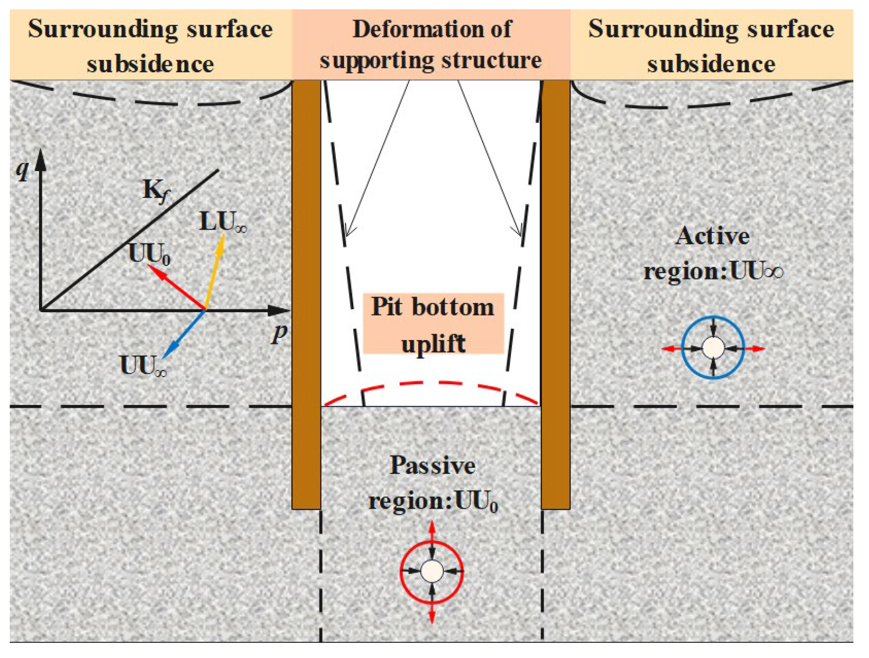
2. Stress Path Analysis of Unloading Soil in Foundation Pit Excavation
3. Unloading Stress Path Tests on Expansive Clays
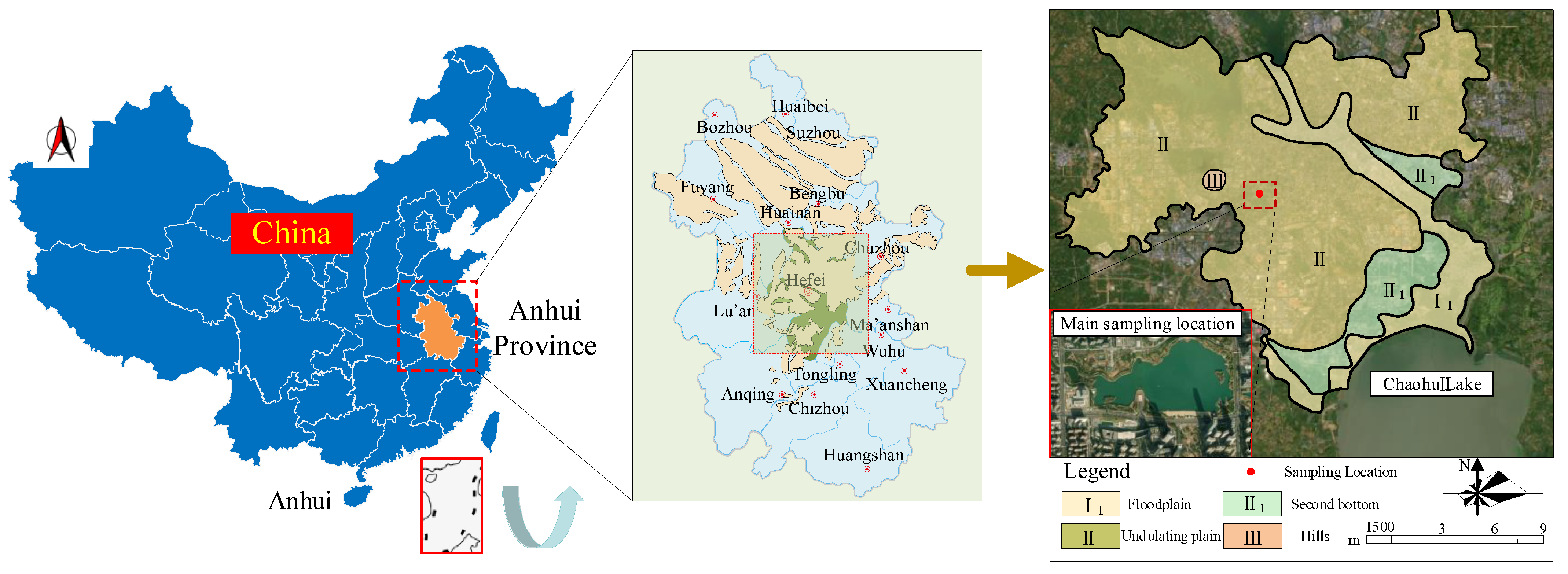
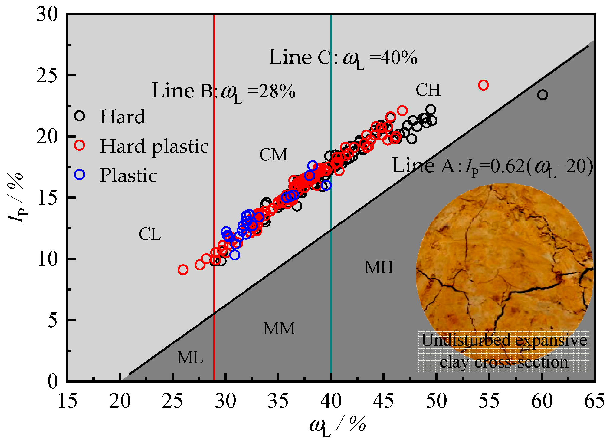
3.1. Soil Sample
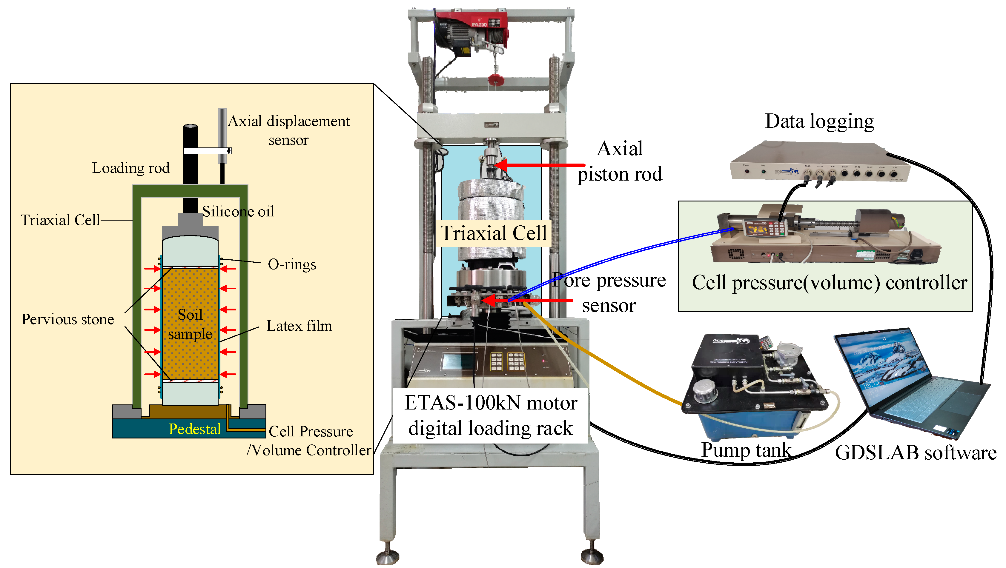
3.2. Test Apparatus
3.3. Sample Program
- (1)
- The CTC test adopted displacement-controlled loading with an axial loading rate of 0.2 mm/min.
- (2)
- The RTC test adopted stress-controlled unloading. The vertical stress remained unchanged during the shearing process, while the lateral stress decreased at an unloading rate of 0.2 kPa/min until the shearing was completed.
- (3)
- The RTE test adopted stress-controlled unloading. The lateral stress remained unchanged, while the axial stress decreased at an unloading rate of 0.2 kPa/min until the shearing was completed.
4. Analysis of Test Results
4.1. Stress–Strain Curves and Macroscopic Characterization of Shear Failure
4.2. Microscopic Properties of Shear Failure
4.3. Analysis of Change Rule of Shear Strength Index
5. Applicability Analysis of Strength Criterion for Expansive Clay under Unloading Path
6. Discussion of Unloading Constitutive Model of Expansive Clay
6.1. Analysis of Unloading Constitutive Model of Expansive Clay
6.2. Calculation Model of Tangent Modulus of Expansive Clay under Unloading Path
6.2.1. Model Construction Ideas
6.2.2. Establishment of Calculation Model for Unloading Tangent Modulus
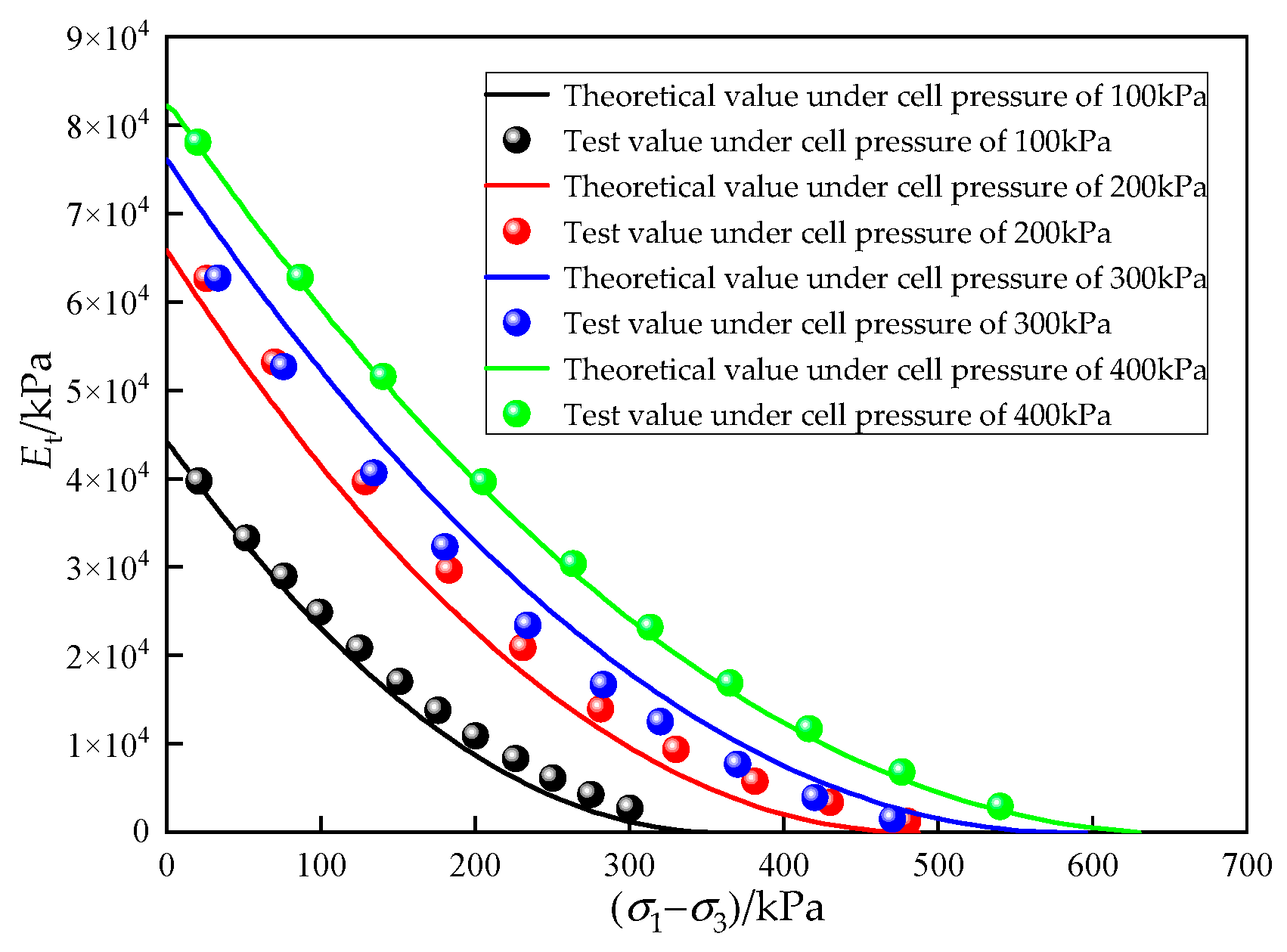
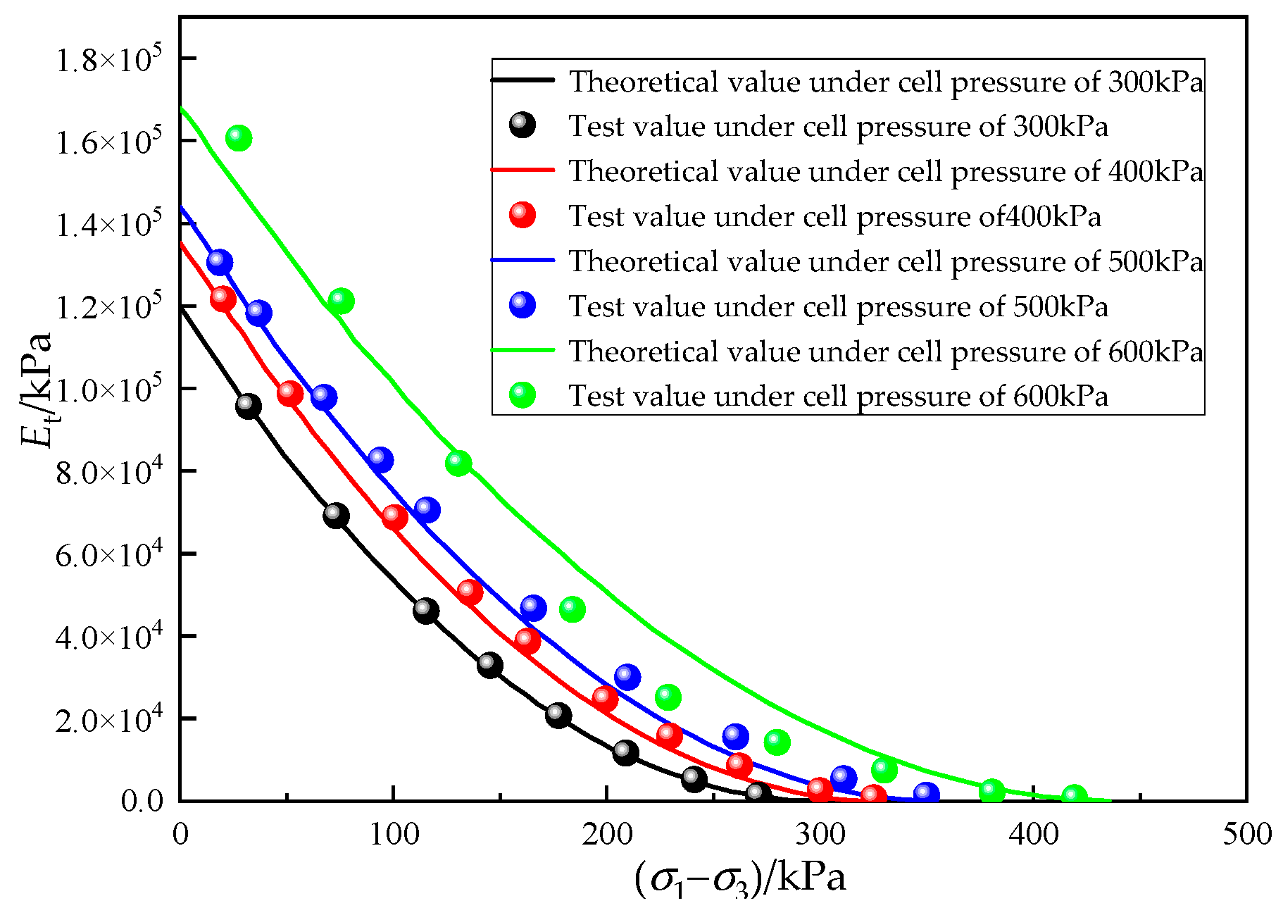
6.3. Verification of Tangent Modulus
7. Conclusions
- (1)
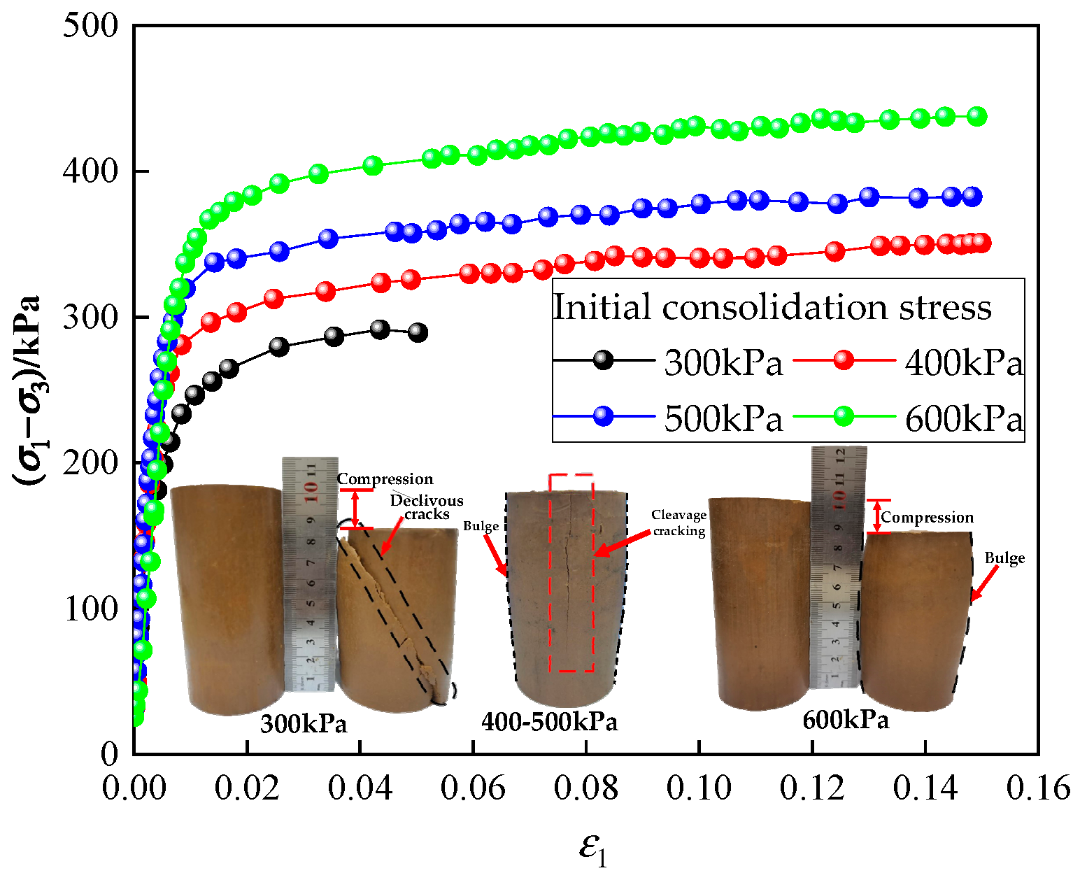
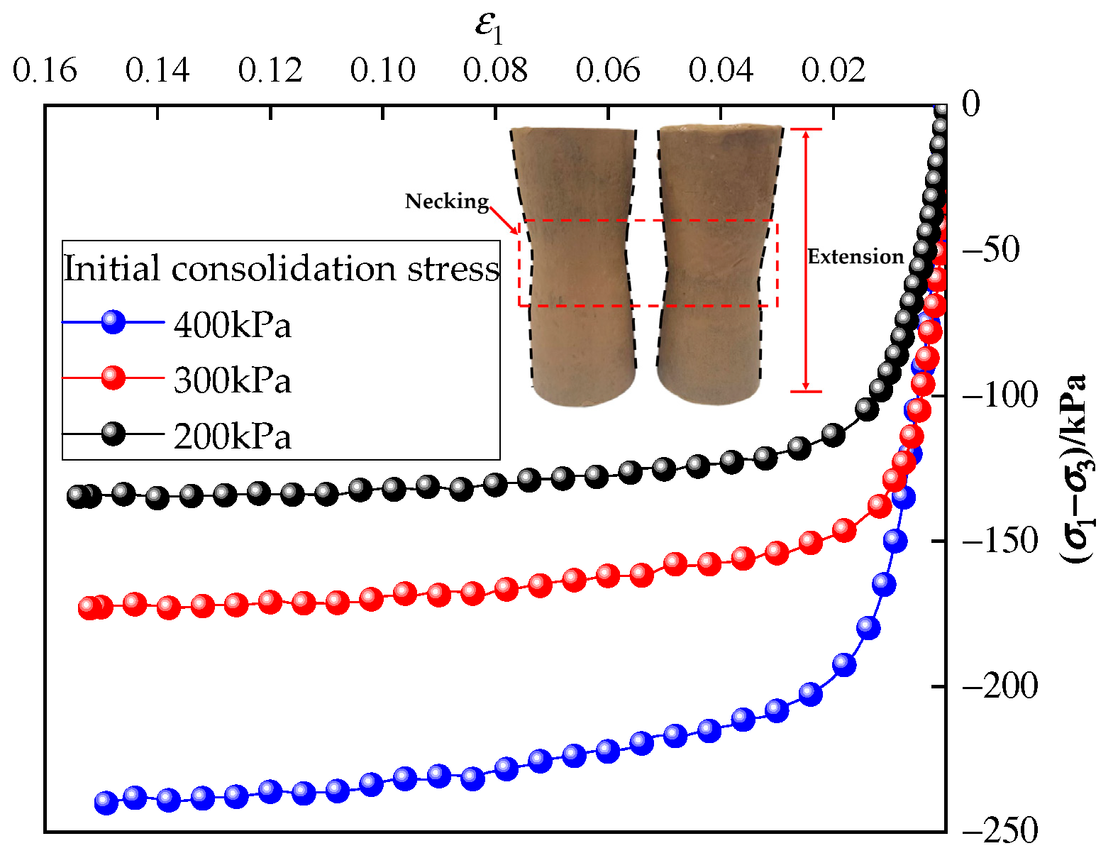
- The stress–strain curves of the three stress paths of the expansive clay were hyperbolic, with typical strain-hardening properties. They belonged to processed hardened soil. The initial tangent modulus of the three soils increased with an increase in the initial consolidation cell pressure. The strain of the samples under lateral unloading and axial unloading lagged behind the increase in deviatoric stress, and the stress–strain curves increased sharply.
- (2)
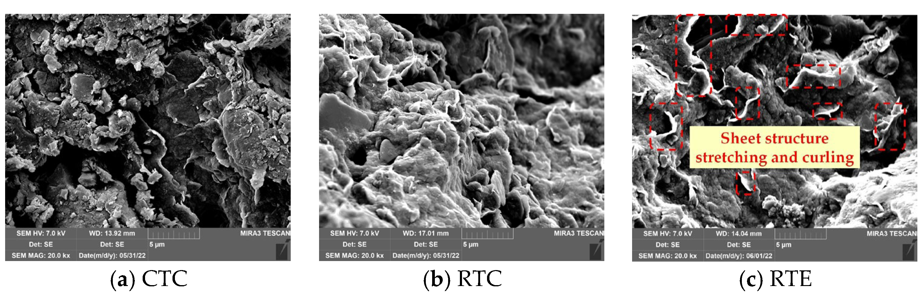
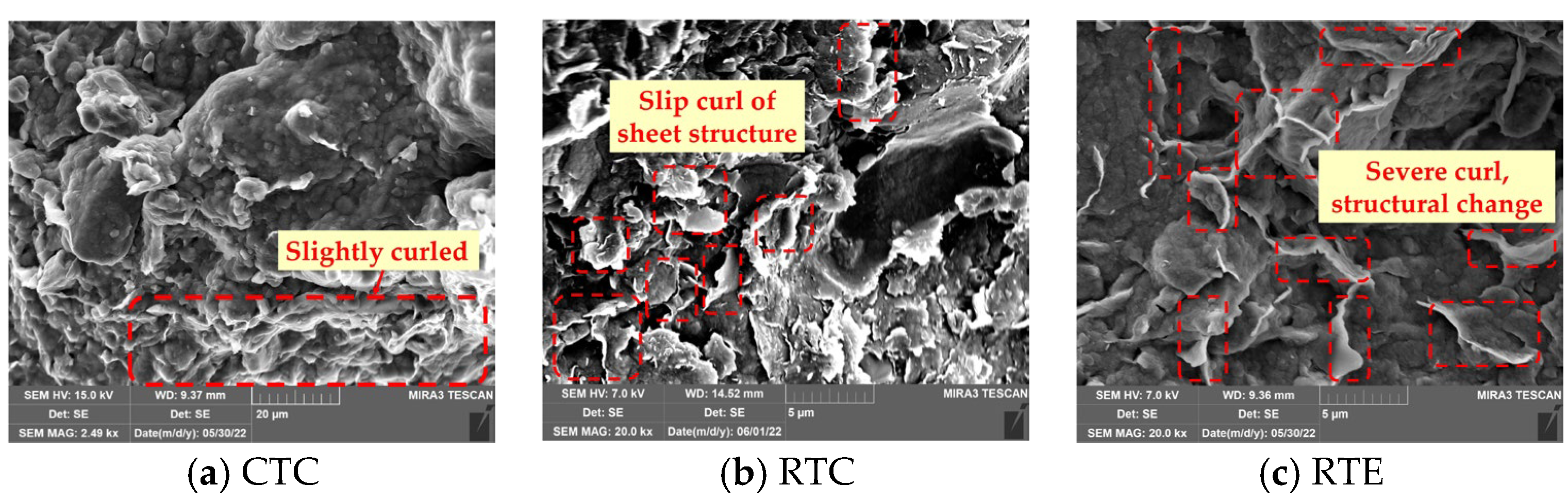
- Under the unloading stress path, the soil particles were involved in the unloading process of stress release. The failure samples of soil sheet elements showed obvious stretching, curling, and slipping phenomena. In terms of failure properties, CTC showed spindle-like swelling failure; RTC showed shear, splitting, and swelling failure with an increase in cell pressure; and RTE showed dumbbell-shaped necking failure.
- (3)
- The strength of the expansive clay was significantly reduced under the unloading stress path. In the RTC path, the c of the expansive clay was reduced by 32.7% compared with the CTC path, and increased by 19%. In the RTE path, c was reduced by 63.5% and the was reduced by 28.7%.
- (4)
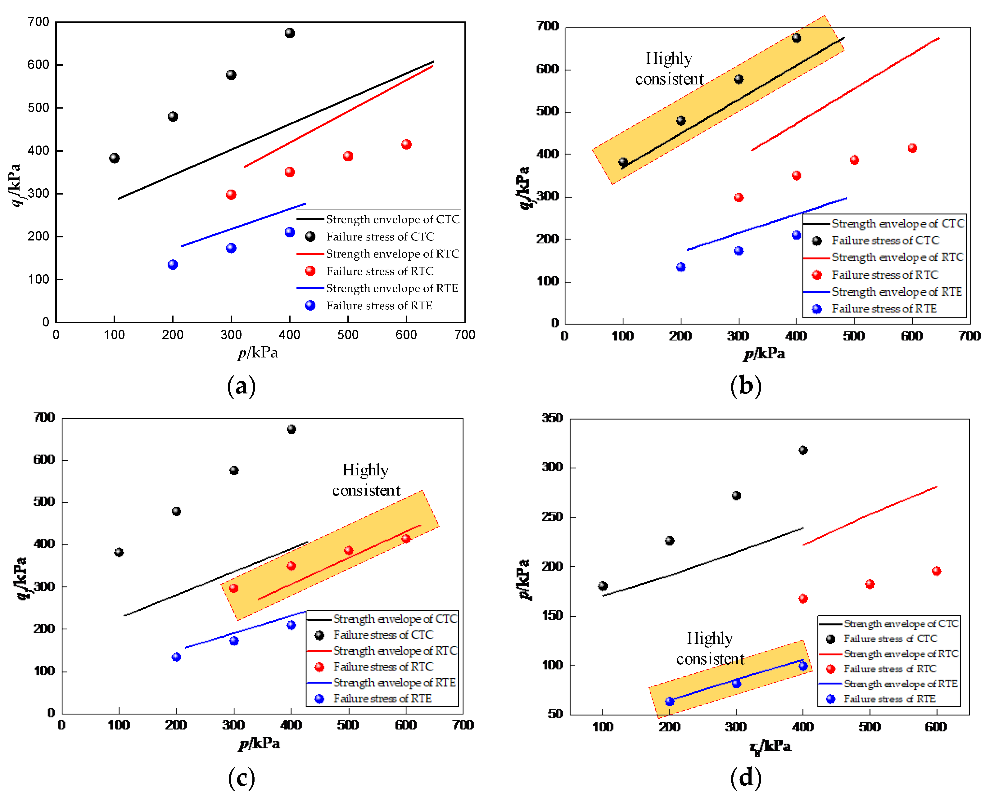
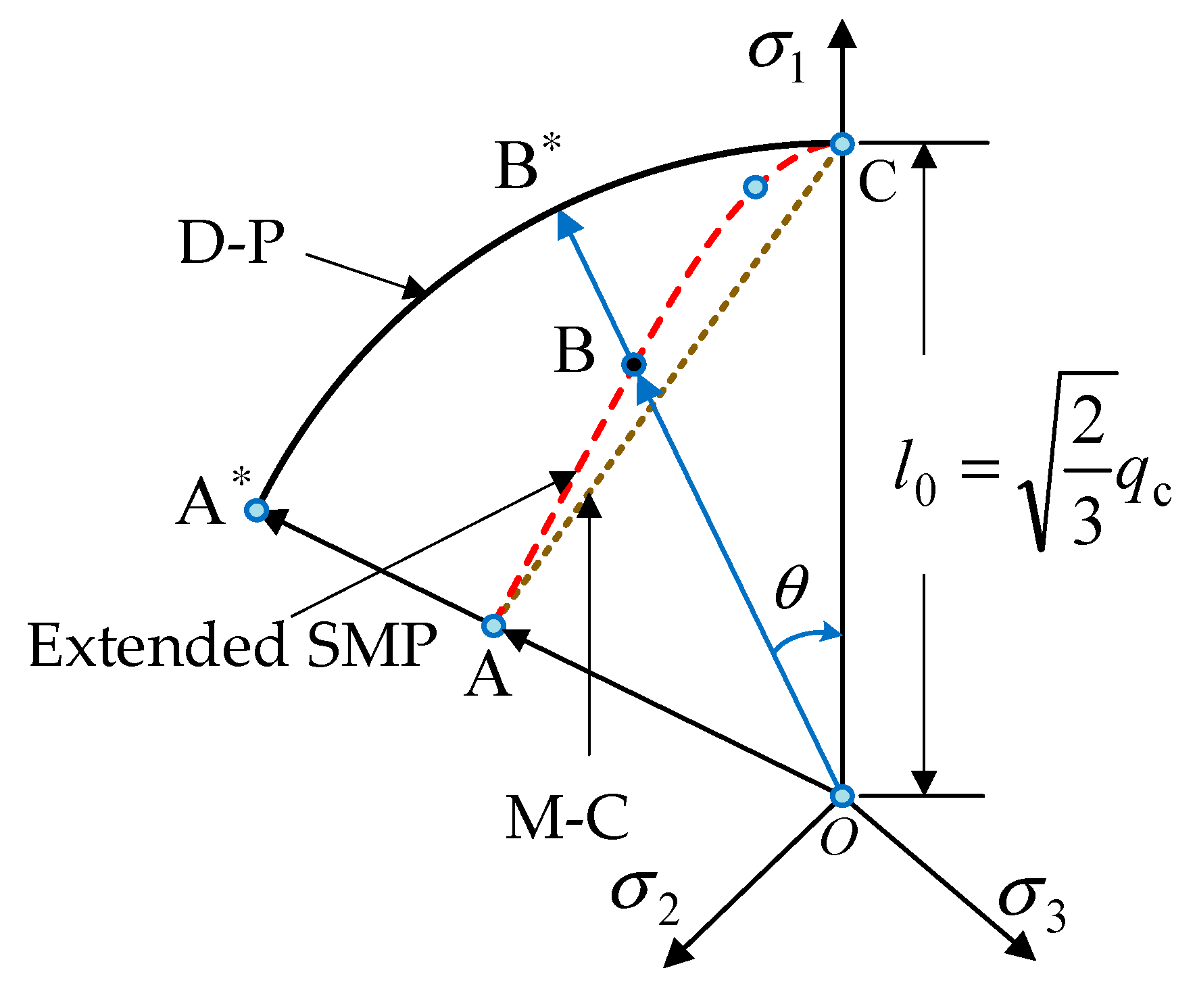
- In the applicability analysis of the four classical criteria, by comparing the predicted value of failure shear stress () with the test value, it was found that the M-C strength criterion was suitable for the CTC stress path, while the D-P strength criterion was suitable for the RTC stress path. The generalized Tresca strength criterion was not suitable. By comparing the calculated value of the extended SMP criterion () with the calculated value of octahedral shear stress () from the measured results, it was found that the error was less than 6%. The extended SMP criterion had an excellent effect on predicting the failure strength of the RTE path.
- (5)
- The traditional Duncan–Chang model had obvious limitations in describing the mechanical behavior of the expansive clay under the RTC and RTE paths. The unloading constitutive model based on the D-P strength criterion and the extended SMP strength criterion could accurately predict the tangent modulus of the expansive clay under the unloading stress path. This verified the reliability of the unloading constitutive model of expansive clay.
Author Contributions
Funding
Data Availability Statement
Conflicts of Interest
References
- Kuo, C.C.; Nelson, J.D. Validation of foundation design method on expansive soils. Geotech. Eng. 2019, 50, 103–111. [Google Scholar]
- Lan, T.; Zhang, R.; Yang, B.Y.; Meng, X. Influence of swelling on shear strength of expansive soil and slope stability. Front. Earth Sci. 2022, 10, 849046. [Google Scholar] [CrossRef]
- Lu, T.S.; He, H.; Liu, S.Y.; Yang, J.; Li, C.; Feng, M. SCPTU-based numerical analyses of an excavation in soft clay. Chin. Civ. Eng. J. 2023, 56, 141–148. [Google Scholar]
- Gao, Z.A.; Kong, L.W.; Wang, S.J. Deformation behavior and shear zone evolution characteristics of undisturbed expansive soil with different fissure directions under plane strain condition. Rock Soil Mech. 2023, 44, 2495–2508. [Google Scholar]
- Li, L.; Zang, M.; Zhang, R.T.; Lu, H.J. Experimental Study on Mechanical Properties of Structured Clay under Different Unloading Rates and Unloading Stress Paths. Buildings 2023, 13, 1544. [Google Scholar] [CrossRef]
- GB 50112-2013; Ministry of Housing and Urban-Rural Development of the People’s Republic of China. Technical Code for Building in Expansive Soil Area. China Building Industry Press: Beijing, China, 2013.
- Huang, W.; Li, J.; Lu, Y.; Li, D.; Mou, Y.; Wu, X.; Jiang, Z.; Li, Z. Mechanical properties of soft soil considering the influence of unloading stress paths. Adv. Civ. Eng. 2021, 2021, 8813882. [Google Scholar] [CrossRef]
- Yang, Y.; Lin, J.; Wu, Y.; Peng, S.; Shao, W.; Yang, L. Energy characteristics of saturated Jurassic sandstone in western China under different stress paths. Deep. Undergr. Sci. Eng. 2024, 1–11. [Google Scholar] [CrossRef]
- Lambe, T.W. Stress Path Method. J. Soil Mech. Found. Div. 1967, 93, 309–331. [Google Scholar] [CrossRef]
- Duncan, J.M.; Chang, C.Y. Nonlinear Analysis of Stress and Strain in Soils. J. Soil Mech. Found. Div. 1970, 96, 1629–1653. [Google Scholar] [CrossRef]
- Gao, Z.Z.; Hu, D.X.; Zhang, Q.Y. Study on constitutive model of soil under complex stress path. Adv. Eng. Sci. 1997, 1, 50–56. [Google Scholar]
- Ying, D.S.; Wang, B.T.; Wang, Y.T. Tangent elastic modulus of Duncan-Chang model for different stress paths. Chin. J. Geotech. Eng. 2007, 9, 1380–1385. [Google Scholar]
- Goto, S.; Burland, J.B.; Tatsuoka, F. Non-linear soil model with various strain levels and its application to axisymmetric excavation problem. Soil Found. 1999, 39, 111–119. [Google Scholar] [CrossRef] [PubMed]
- Roscoe, K.H.; Schofield, A.N.; Thurairajah, A. Yielding of clay in states wetter than critical. Geotechnique 1963, 13, 211–240. [Google Scholar] [CrossRef]
- Ma, P.C.; Ke, H.; Tong, X. Nonlinear constitutive model of soil–bentonite based on triaxial tests along different stress paths. Can. Geotech. J. 2021, 58, 682–694. [Google Scholar] [CrossRef]
- Roscoe, K.H.; Burland, J.B. On the Generalised Stress-Strain Behavior of “Wet” Clay; Cambridge University Press: Cambridge, UK, 1968; pp. 535–609. [Google Scholar]
- Robert, S.C.; Kenneth, L.I. Response of granular soil along constant stress increment ratio path. J. Geotech. Eng. 1990, 116, 355–376. [Google Scholar] [CrossRef]
- Matsuoka, H.; Yao, Y.; Sun, D. The Cam-clay models revised by the SMP criterion. Soils Found. 1999, 39, 81–95. [Google Scholar] [CrossRef]
- Sun, D.A.; Yao, Y.P.; Yin, Z.Z. Generalization of elasto-plastic model with two yield surfaces based on SMP criterion. Chin. J. Geotech. Eng. 1999, 21, 631–634. [Google Scholar]
- Yao, Y.P.; Wang, N.B. Unified hardening equation for soils in complex stress paths. Chin. J. Rock Mech. Eng. 2023, 42, 2041–2047. [Google Scholar]
- Zou, B.; Yao, Y.P.; Lu, D.C. Qinghua model revised by SMP criterion. Chin. J. Rock Mech. Eng. 2005, 24, 4303–4307. [Google Scholar]
- Lu, D.C. A constitutive model for soils considering stress paths based on generalized nonlinear strength theory. Chin. J. Rock Mech. Eng. 2007, 26, 1512. [Google Scholar]
- Zhang, K.Y.; Zang, Z.J.; Li, W.; Wen, D.B.; Nai, C.F. Three-dimensional elastoplastic model of soil with consideration of unloading stress path and its experimental verification. Rock Soil Mech. 2019, 40, 1313–1323. [Google Scholar]
- Yin, X.; Li, M.; Xia, B.; Shen, N.; Jiang, G.; Zhong, J. Shear behavior of saturated silt under complex unloading paths. Chin. J. Geotech. Eng. 2023, 45, 75–78. [Google Scholar]
- Qiu, Y.; Ding, W.; Zhao, T.; Wang, X.; Qiao, Y. Asymmetrical deformation characteristics and mechanisms of deep excavations induced by one-side unloading. Chin. J. Geotech. Eng. 2024, 46, 199–206. [Google Scholar]
- Li, F.G.; Ji, R.H.; Wang, X.M. Investigation and Evaluation of Disaster-Causing Special Soil in Anhui Province; Anhui Province Geological Prospecting Bureau Second Hydrological Engineering Geology Survey Institute: Wuhu, China, 2008. [Google Scholar]
- GB/T 50123-2019; Standard for Geotechnical Test Methods. Standardization Administration of the People’s Republic of China: Beijing, China, 2019.
- Zhang, T.; Peng, S.L.; Cao, G.Y.; Zhang, Y.J. Experimental study on expansive soil lateral unloading and analysis on its normalized characteristics. Water Resour. Hydropower Eng. 2023, 54, 175–186. [Google Scholar]
- Li, X.; Jia, Y.; Wang, Z.; Sun, Y.; Yin, S. Step-changed strain rate effect on the mechanical properties of undisturbed expansive clay. Eur. J. Environ. Civ. Eng. 2024, 28, 38–52. [Google Scholar] [CrossRef]
- Yu, M.H.; Peng, Y.J. Advances in strength theories for materials under complex stress state in the 20th century. Adv. Mech. 2004, 34, 529–560. [Google Scholar] [CrossRef]
- Cai, M.F. Rock Mechanics and Engineering; Science Press: Beijing, China, 2013. [Google Scholar]
- Matusoka, H. Prediction of plane strain strength for soils from triaxial compression. In Proceedings of the 10th International Conference on soil Mechanics and Foundation Engineering, Stockholm, Sweden, 15–19 June 1981; Volume 5, pp. 682–683. [Google Scholar]
- He, S.X.; Long, L.H.; Yang, X.Q.; He, Y. Experimental study of yield property of clayey soil under unloading. Rock Soil Mech. 2008, 29, 449–452. [Google Scholar]
- Li, J.J.; Kong, L.W.; Jin, L. Stress history and time effect on shear modulus of expansive soils. Arab. J. Geosci. 2022, 15, 35. [Google Scholar] [CrossRef]
- Kondner, R.L. Hyperbolic stress-strain response: Cohesive soils. J. Soil Mech. Found. Div. 1963, 89, 115–143. [Google Scholar] [CrossRef]
- Shao, D.C. A modified duncan-chang model and its application to numerical simulation of earth-rock dam. China Three Gorges Univ. (Nat. Sci.) 2015, 37, 21–24. [Google Scholar]


| Natural Moisture Content (%) | Dry Density (g/cm3) | Void Ratio | Plastic Limit (%) | Liquid Limit (%) | Plasticity Index | Free-Expansion Rate (%) |
|---|---|---|---|---|---|---|
| 23.4 | 1.73 | 0.743 | 21.3 | 39.6 | 18.3 | 47.1 |
| Maximum Vertical Load kN | Maximum Cell Pressure MPa | Load Sensor Range kN | Pore Pressure Sensor Range MPa | Axial Displacement Sensor Range mm |
|---|---|---|---|---|
| 100 | 32 | 100 | 32 | ±25 |
| Stress Path Types | Loading (Unloading) Methods | Consolidation Stress/kPa | Simulated Soil Position | Shearing Rate |
|---|---|---|---|---|
| CTC | 100, 200, 300, 400 | conventional axial loading | load 0.2 mm/min | |
| RTC | 300, 400, 500, 600 | passive zone | unload 0.2 kPa/min | |
| RTE | 200, 300, 400 | active zone |
| Stress Paths | Maximum Principal Stress /kPa | Medium Principal Stress /kPa | Minimum Principal Stress /kPa | Failure Deviatoric Stress ()/kPa | Internal Friction Angle | Cohesive Force |
|---|---|---|---|---|---|---|
| CTC | 499.18 | 100 | 100 | 399.18 | 19.1 | 101.7 |
| 711.55 | 200 | 200 | 511.55 | |||
| 925.81 | 300 | 300 | 625.81 | |||
| 1067.68 | 400 | 400 | 667.68 | |||
| RTC | 300 | 4.97 | 4.97 | 295.03 | 22.73 | 68.4 |
| 400 | 49.48 | 49.48 | 350.52 | |||
| 500 | 112.86 | 112.86 | 387.14 | |||
| 600 | 184.80 | 184.80 | 415.20 | |||
| RTE | 200 | 200 | 65.27 | 134.73 | 13.64 | 37.1 |
| 300 | 300 | 126.92 | 173.08 | |||
| 400 | 400 | 185.40 | 214.60 |
| Strength Criteria | -Plane Expression | Strength Parameters | |
|---|---|---|---|
| Mohr–Coulomb [30] | |||
| Drucker–Prager [31] | |||
| Generalized Tresca [30] | |||
| Extended SMP [32] | , , | ||
| Stress Paths | Strength Criterion Applicability Grade |
|---|---|
| CTC | M-C > extended SMP > generalized Tresca > D-P |
| RTC | D-P > extended SMP > generalized Tresca > M-C |
| RTE | extended SMP > D-P = generalized Tresca = M-C |
Disclaimer/Publisher’s Note: The statements, opinions and data contained in all publications are solely those of the individual author(s) and contributor(s) and not of MDPI and/or the editor(s). MDPI and/or the editor(s) disclaim responsibility for any injury to people or property resulting from any ideas, methods, instructions or products referred to in the content. |
© 2024 by the authors. Licensee MDPI, Basel, Switzerland. This article is an open access article distributed under the terms and conditions of the Creative Commons Attribution (CC BY) license (https://creativecommons.org/licenses/by/4.0/).
Share and Cite
Peng, S.; Li, Z.; Cheng, H.; Xu, Y.; Zhang, T.; Cao, G. Mechanical Response Characteristics and Tangent Modulus Calculation Model of Expansive-Clay Unloading Stress Path. Buildings 2024, 14, 2497. https://doi.org/10.3390/buildings14082497
Peng S, Li Z, Cheng H, Xu Y, Zhang T, Cao G. Mechanical Response Characteristics and Tangent Modulus Calculation Model of Expansive-Clay Unloading Stress Path. Buildings. 2024; 14(8):2497. https://doi.org/10.3390/buildings14082497
Chicago/Turabian StylePeng, Shilong, Zhijun Li, Hua Cheng, Yuhao Xu, Ting Zhang, and Guangyong Cao. 2024. "Mechanical Response Characteristics and Tangent Modulus Calculation Model of Expansive-Clay Unloading Stress Path" Buildings 14, no. 8: 2497. https://doi.org/10.3390/buildings14082497
APA StylePeng, S., Li, Z., Cheng, H., Xu, Y., Zhang, T., & Cao, G. (2024). Mechanical Response Characteristics and Tangent Modulus Calculation Model of Expansive-Clay Unloading Stress Path. Buildings, 14(8), 2497. https://doi.org/10.3390/buildings14082497