Article

Experimental Study on Axial Compressive Performance of Recycled Steel Fiber Reinforced Concrete Short Columns with Steel Pipes

1
College of Environment and Civil Engineering, Chengdu University of Technology, No. 1, East Third Road, Erxianqiao, Chengdu 610059, China
2
College of Civil Environment and Architecture, Nanchang Hangkong University, Nanchang 330063, China
3
State Key Laboratory of Geohazard Prevention and Geoenvironment Protection, No. 1, East Third Road, Erxianqiao, Chengdu 610059, China
*
Author to whom correspondence should be addressed.
Buildings 2024, 14(8), 2498; https://doi.org/10.3390/buildings14082498
Submission received: 28 June 2024 / Revised: 21 July 2024 / Accepted: 8 August 2024 / Published: 13 August 2024

Abstract

:
To explore the axial compressive mechanical properties of steel tube recycled steel fiber reinforced concrete short columns (STRSFRCSCs), axial compression tests were conducted on ten STRSFRCSCs and two steel tube reinforced concrete short columns (STRCSCs), mainly analyzing the effects of recycled steel fiber (RSF) content, steel content, and concrete strength grade on their mechanical properties. The results showed that different RSF contents had no significant effect on the failure mode of the specimens, while the concrete strength grade and steel content had a significant effect on the failure mode. When the steel content was 2.84%, the specimens experienced shear failure, while when the steel content was 4.24%, they experienced waist drum failure. As the RSF content increased, the peak strain during the loading process of the specimens decreased, and the transverse deformation coefficient at the peak decreased. The addition of RSF significantly improved the ductility performance of the specimens. When the volume fraction of RSF was 2%, the bearing capacity of the specimens increased the most, reaching 13.4%, and the ductility coefficient gradually increased. The axial compressive bearing capacity and combined elastic modulus of the specimens increased with the increase in concrete strength grade, RSF content, and steel content.

1. Introduction

Concrete-filled steel tubes (CFSTs) utilize the restraining effect of steel tubes on concrete, improving its axial compressive strength, enhancing its ductility, and overcoming its brittle defects [1,2,3,4,5]. In addition, the constraint of concrete on steel pipes reduces the local buckling of steel pipes due to compression. The combination of steel pipes and concrete fully utilizes the advantages of the two materials, avoiding their shortcomings, and is an excellent structural form [6,7,8,9,10,11]. At present, steel tube concrete has been widely used in high-rise building structures, heavy-duty industrial plants, large-span bridge engineering, and underground space engineering [12,13,14,15].
As the strength of concrete increases, the bearing capacity of CFST structures decreases rapidly after reaching its peak load under axial pressure, and only stabilizes after a sharp decrease [16,17,18]. Moreover, in general, the higher the strength of concrete, the more significant the decrease in bearing capacity after the peak point, which can lead to insufficient ductility performance of components and have a significant adverse effect on the seismic performance of the structure [19,20,21,22,23]. According to existing research results, following the Hanshin earthquake in Japan and the Chi Chi earthquake in Taiwan, China, a large number of CFST columns were seriously damaged due to insufficient ductility of components [24,25,26,27]. Therefore, enhancing the ductility performance of CFST structural components is an effective way to improve their seismic bearing capacity, which is more important than enhancing the bearing capacity of components [28,29,30].
Steel fiber reinforced concrete is an effective method to improve the ductility and toughness of concrete, which is both economical and efficient in improving the ductility of concrete [31,32]. In addition, with the rapid development of self-compacting concrete, steel fiber self-compacting steel tube concrete is increasingly being used in steel tube concrete structures [33]. Due to the global trend of green building materials and the implementation of China’s low-carbon development strategy, more and more solid waste materials are being used to enhance the ductility of concrete, such as waste rubber fibers, waste plastic fibers, waste tire steel fibers, etc. [34,35,36]. From the perspective of enhancing ductility and toughness, waste tire steel fibers have the optimal effect on enhancing toughness and improving ductility performance of concrete [37,38]. At present, there are two main sources of recycled steel fibers (RSF): one is the steel wire generated from the treatment of waste tires, and the other is the steel fiber formed by sorting the remaining materials from mechanical processing [39,40]. The steel wires generated from the treatment of waste tires can be called waste steel fibers, which are added to concrete to form waste steel fiber concrete. Research on waste steel fiber concrete is already in the preliminary stage [41]. However, the steel fibers formed by sorting the leftover materials generated by mechanical processing can be called RSF, and there is currently very little research on RSF concrete [42,43].
Only a small amount of research has shown that waste steel fibers can improve the compressive strength of concrete, but the improvement is relatively small, generally not exceeding 30% [43]. In terms of improving the flexural strength of concrete, the improvement is significant, usually exceeding 50% and up to 150% [44,45]. Furthermore, when the volume fraction of RSF is less than 2%, its ability to improve concrete is more significant, with significant improvements in both compressive and flexural strength. However, when the volume fraction of RSF exceeds 2%, its improvement in compressive strength of concrete is almost zero, but it still has an enhancing effect on tensile and flexural strength. However, this improvement is generally not more than 20%, which is significantly less effective than the effect of a fraction below 2%. Through impact tests on RSF concrete, it was found that RSF significantly increased the impact resistance of concrete and improved the failure mode of concrete after impact [46,47,48,49,50]. Compared to plain concrete, RSF concrete has more cracks and finer cracks after impact failure, and the integrity of the test block is significantly better than that of ordinary concrete [51].
Rice husk ash (RHA) is an agricultural waste, and replacing some Portland cement with RHA will help reduce carbon dioxide emissions in the atmosphere [19]. There are up to 150 million hectares of arable land worldwide used for rice cultivation. A large amount of rice husks are produced during the rice production process, which, if not effectively treated, can pollute the environment. The use of RHA in concrete has good environmental and economic benefits [20,21]. The RHA formed after rice husk incineration is a type of amphoteric low-carbon silica, which is a volcanic ash material that can improve the strength and corrosion resistance of concrete and reduces the chloride ion permeability and permeability of concrete [22]. The reaction of RHA improves concrete physically and chemically through the filler effect in the porous structure. In addition, RHA also improves the workability of concrete.
The axial compressive bearing capacity of steel fiber reinforced concrete with steel pipes is influenced by the strength of the concrete, the amount of steel fiber, and the strength of the steel. The amount of steel fiber has a significant effect on the ductility of the specimen and has a significant impact on the bearing capacity and failure mode [52,53,54,55]. Short cut steel fibers significantly improve the bearing capacity and ductility of high-strength concrete filled steel tubes. For columns with a large aspect ratio, using steel fiber reinforced steel tube concrete has better stability, higher bearing capacity, and better energy dissipation performance than ordinary steel tube concrete. The bearing capacity of the steel fiber reinforced concrete arch structure is 40% higher than that of the steel pipe arch structure, with better stability. Local buckling and deformation of the steel pipe are also well constrained, which improves the stiffness of the entire arch structure and reduces the deformation of the structure under dynamic loads. In the structure of heavy-duty factory buildings, the use of steel fiber reinforced steel tube concrete structural columns not only has greater load-bearing performance, but also better ductility and toughness, and more significant energy absorption capacity. It has a very obvious energy dissipation performance for the vibration generated by cranes in heavy-duty factory buildings [56,57,58,59]. In addition to the research on mechanical properties of steel fiber reinforced steel tubes, researchers have conducted long-term exposure tests, freeze–thaw cycle tests, etc., to evaluate its durability under different environmental conditions. Moreover, the steel fibers currently used in steel fiber reinforced steel tube concrete are mainly virgin steel fibers, while the use of RSF in steel tube concrete structures is still very rare. Therefore, the research on steel tube concrete structures using RSF still has exploratory significance.
The research on the addition of RSF formed by machining surplus materials into concrete to form composite materials is still in its infancy, and there are few studies on the addition of RSF to concrete to form steel tube steel fiber reinforced concrete structures. Therefore, there are almost no research results on the axial compression of steel tube recycled steel fiber reinforced concrete short columns (STRSFRCSCs). Based on this, the study of the axial compression mechanical properties of STRSFRCSCs has great exploratory significance. According to the specifications of the [60,61], axial compression tests were conducted on ten STRSFRSCs and two STRCSCs, mainly to study their deformation characteristics, failure modes, and post peak mechanical properties under axial compression load. A calculation method for the axial compression bearing capacity of STRSFRCSCs was established, providing reference for further research on STRSFRCSCs [62,63].

2. General Situation of Experiment

2.1. Material Properties

2.1.1. Steel Pipe

The experiment used Q235B ordinary welded steel pipe, with a peripheral diameter of 140 mm, wall thicknesses of 2 mm and 3 mm respectively, a length of 400 mm, and a length to diameter ratio of L/D = 2.86, meeting the requirements for short columns (L/D ≤ 4). Referring to the “Metallic materials–Test pieces for tensile testing (GB6397-86)” for sampling, three tensile specimens were taken from steel pipes of different thicknesses, and the tensile mechanical properties of the steel were tested according to the “Metallic materials–Tensile testing–Part1: Method of test at room temperature (GB/T228.1-2010)”. The performance indicators of steel are shown in Table 1.

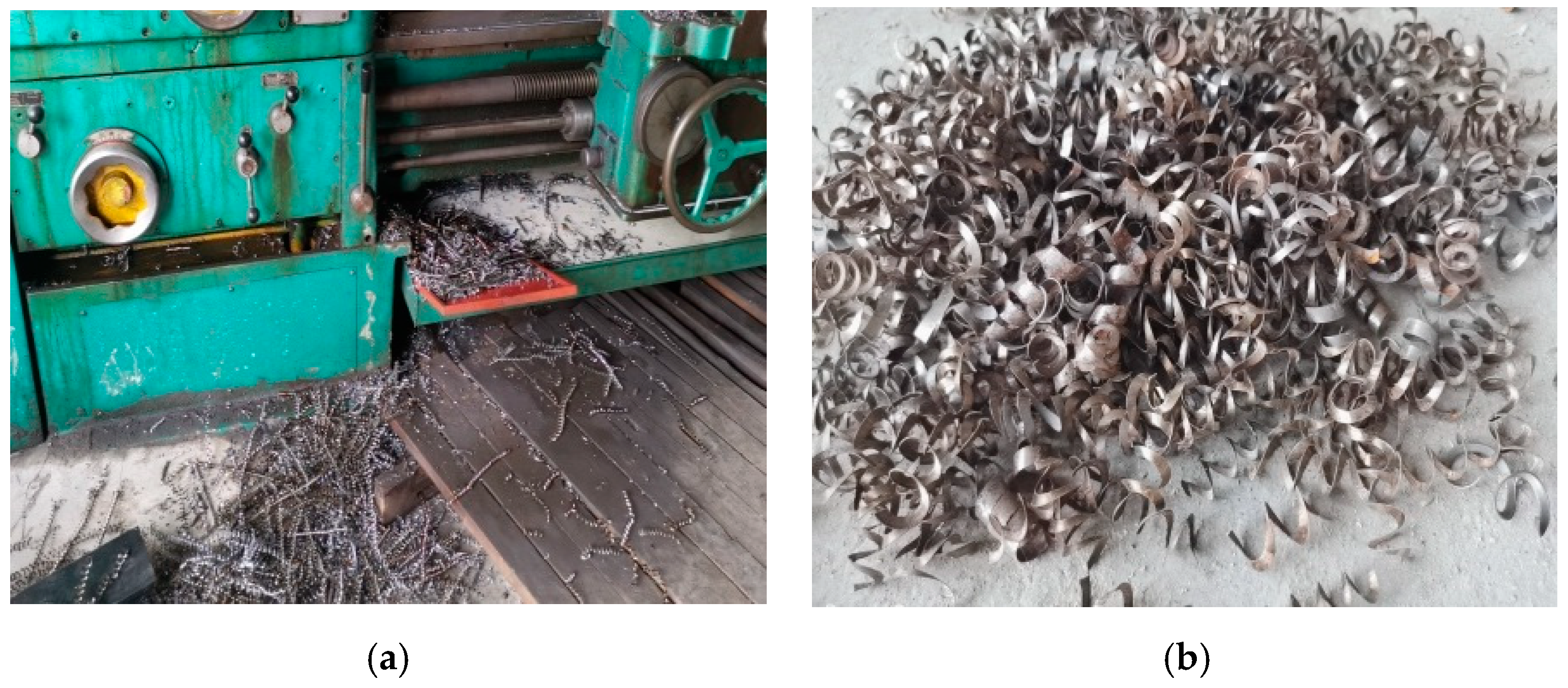
2.1.2. Recycled Steel Fibers

RSF is cut during the process of removing the tool from the workpiece in mechanical machining, with a three-dimensional spiral shape and varying lengths. After obtaining RSF from the factory, it is cut into small sections using steel scissors, and then the rusted and heavily polluted parts are removed. The remaining parts are left to air dry for later use. RSF has a length range of 20~40 mm, an average thickness of 0.36 mm, an average width of 2.68 mm, an average tensile strength of 385.3 MPa, and an elastic modulus of 2.02 × 10⁵ MPa. The volume fraction of RSF in concrete is 0%, 0.5%, 1.0%, 1.5%, and 2.0%, respectively. The machining process and shape of RSF are shown in Figure 1.

2.1.3. Concrete

The concrete strength grades are C30 and C50, and their mix design is shown in Table 2. During the processing and production of components, concrete samples are taken from each strength grade, with 3 groups of concrete samples taken and made into 100 × 100 × 100 cubic test blocks. After 28 days of standard curing, the cubic compressive strength test is conducted, and the final values are taken as the average of the 3 test blocks. The test results are shown in Table 3.

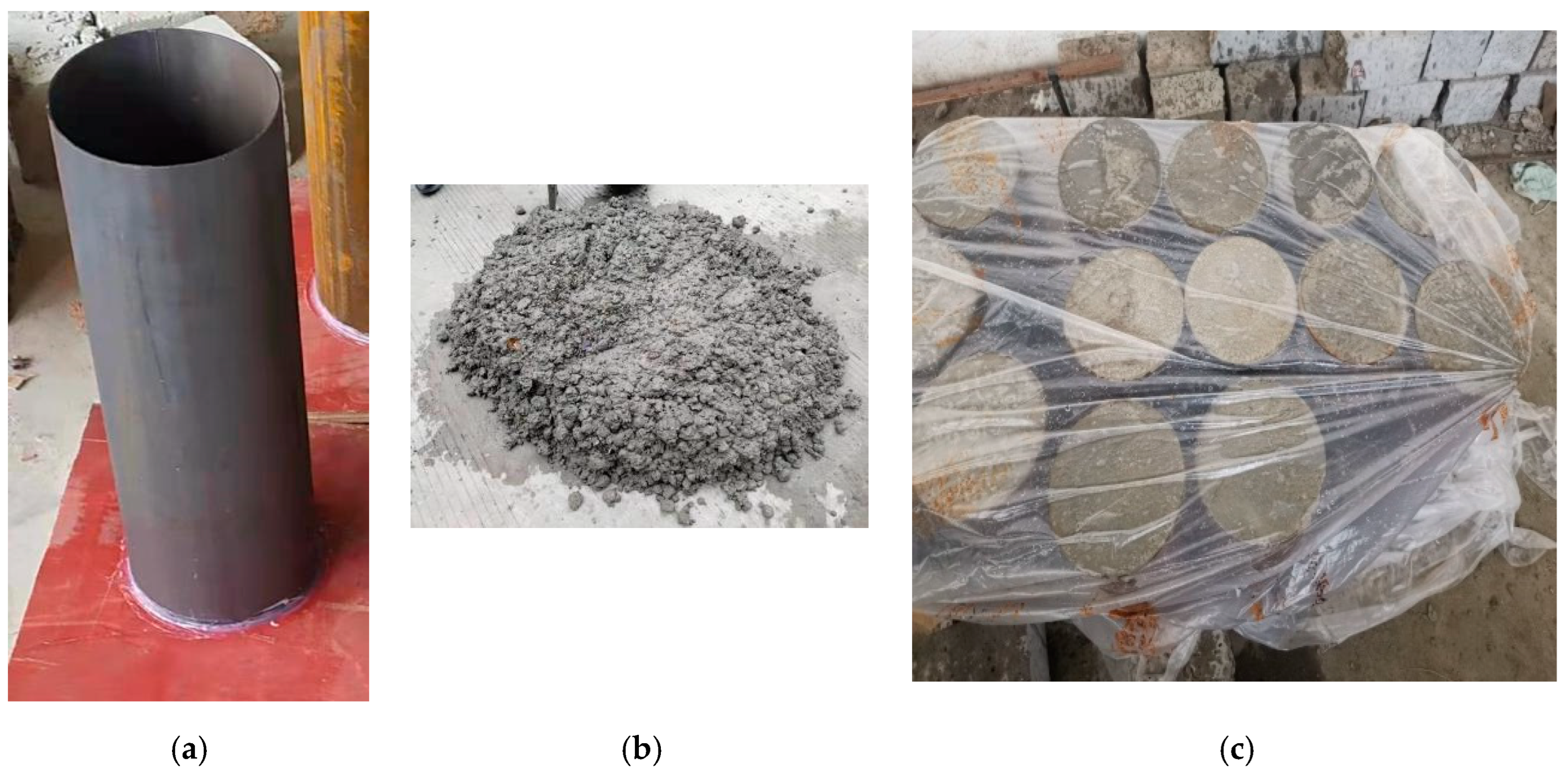
2.2. Test Piece Design and Production

A total of 10 STRSFRCSCs and 2 CFSTSCs were designed for the experiment. The experimental parameters are three variables: RSF volume fraction, steel content, and concrete strength grade. To ensure the flatness of both ends of a specimen and minimize errors during the testing process, the steel pipe used in the test is laser cut at the steel processing plant, with a length of 400 mm and a length error of less than 2 mm. Before pouring concrete, we first cleaned the floating rust on the inner wall of the steel pipe, then sealed the bottom with a wooden board and fixed it with hot melt adhesive. When pouring concrete, we used a steel rod to compact it, and then placed it on a vibration table with an amplitude of 0.3–0.6 mm to continue compacting until there was floating slurry on the surface of the specimen and the aggregate no longer settled. We then placed the specimen in a dry and cool place, covered it with plastic film on top of the steel pipe concrete, and allowed it to cure under natural conditions for more than 28 days until the concrete reached the design strength. Figure 2 shows the production and maintenance of the specimens. The specific design parameters of each specimen are shown in Table 4.

2.3. Test Method

2.3.1. Loading Equipment and Measurement Point Layout

The loading equipment and measurement point layout are shown in Figure 3, and the experiment was completed on a 10,000 kN electro-hydraulic servo long column pressure testing machine in the laboratory. In order to more clearly observe the position of surface deformation of the steel pipe and the entire process of bulging development, after 28 days of natural curing, rust was removed from the surface of the specimen and the surface was polished, and the concrete at both ends of the specimen was polished flat. Then, the four directions in the middle of the test piece were finely polished, and 400-grit sandpaper was used to polish the corresponding adhesive area of the variable piece. Finally, a 50 mm × 50 mm grid line was drawn with a white pen to determine the location of the steel pipe bulging.
After the entire processing work is completed, the specimen is installed on the loading end plate of the pressure testing machine, and the test load is tested through pressure sensors and automatically collected by the computer. Four sets of resistance strain gauges are pasted along the longitudinal and circumferential directions on the two symmetrical directions of the outer wall of the steel pipe in the middle of the specimen to measure the surface strain changes of the steel pipe. Two displacement sensors are symmetrically arranged on both sides of the specimen to measure the compression deformation during the axial compression process.

2.3.2. Loading Method

When the applied load is less than 0.7 times the estimated ultimate bearing capacity (0.7 Nu), the increase in load at each level is 0.1 Nu, and the load at each level lasts for 2 min. The three-stage control method is adopted throughout the entire loading process of the specimen. Before yielding, the load control method is used, and after yielding, the displacement control method is used. When the applied load reaches 0.7 times the estimated ultimate bearing capacity (0.7 Nu), the increase in load for each level is 0.05 Nu. After the increase, each level of load is continuously loaded for 2 min. When the applied load reaches the peak load, it changes from load control to displacement control, with a displacement loading rate of 1 mm/min.
There are three principles of the unloading system. One is that the longitudinal compression of the specimen reaches 30 mm (7.5% of the specimen height). The second is that the concrete in the core area has burst, the longitudinal weld seam of the steel pipe raw material has burst, and other parts of the steel pipe surface have cracked. Thirdly, after reaching the peak load, the bearing capacity of the specimen decreases to 85% of the peak load. If any of the above three event occurred, we stopped the loading test and stopped unloading.

3. Result Analysis and Discussion

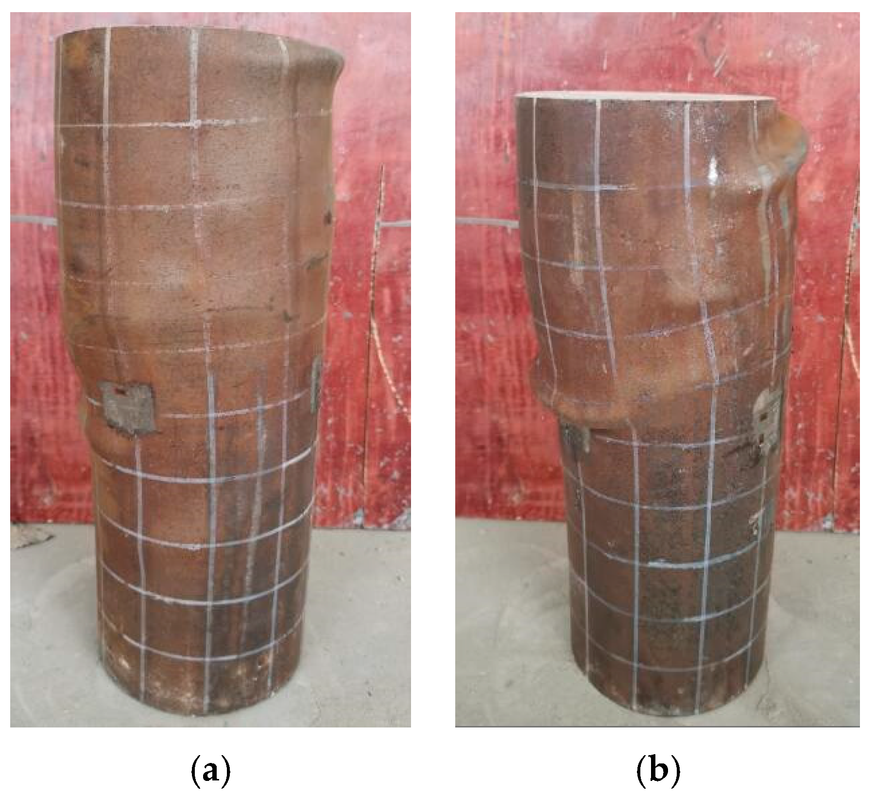
3.1. Deformation Process and Failure Mode

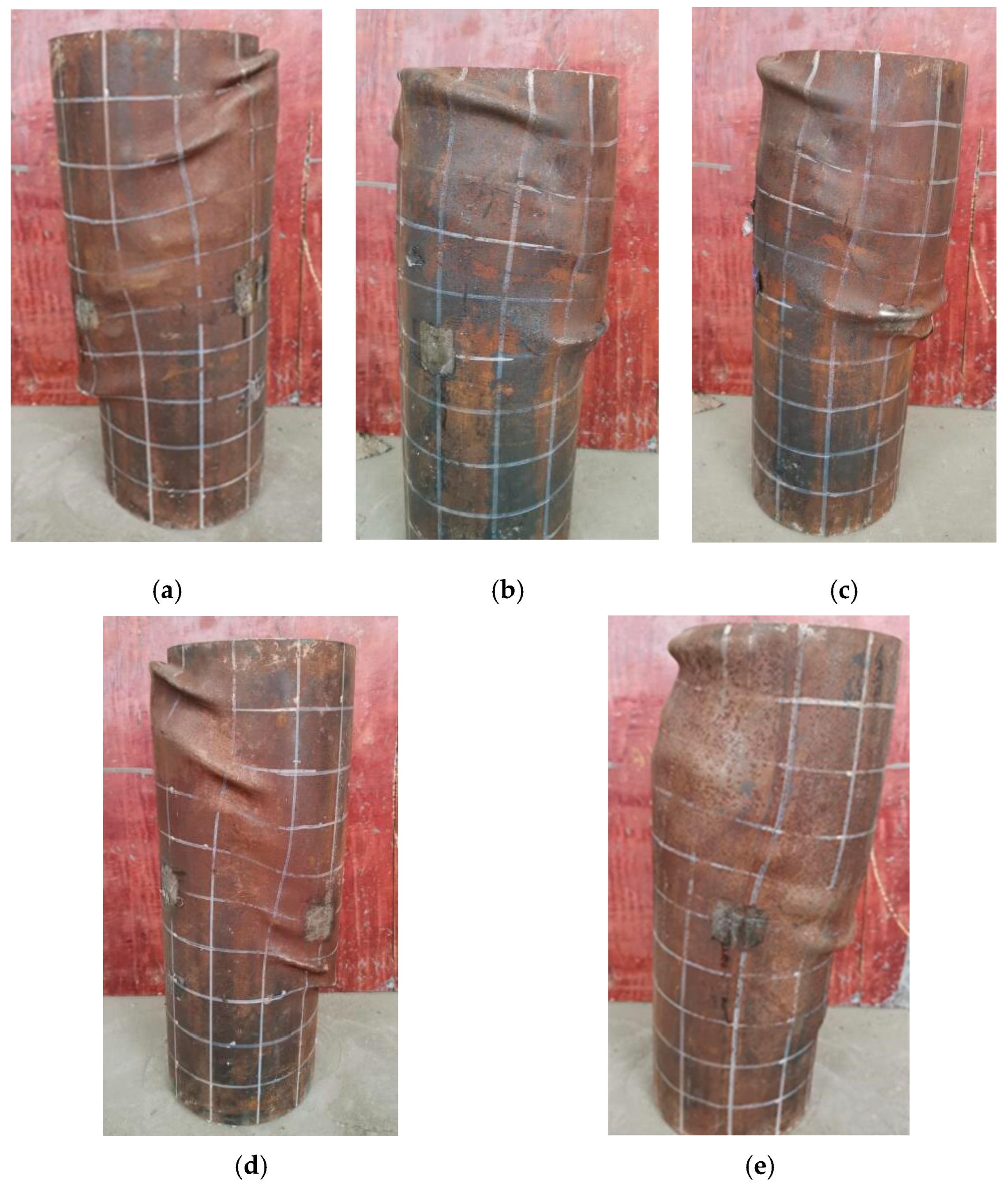
3.1.1. C30-2 Series Specimens

Figure 4 shows the final failure mode of the specimens with a concrete strength grade of C30 and a steel content of 2.84%. In the early stage of loading, the specimens were in an elastic working state with uniform stress, and there was no significant change in the surface of the steel pipe. With the increase in RSF content, the specimens began to show peeling and slag shedding, and the corresponding load values for deformation, bulging, and yield showed a significant increasing trend overall. When the RSF content was 0%, 0.5%, 1.0%, 1.5%, and 2.0%, the corresponding load values for the occurrence of peeling and slag on the steel surface were 570 kN (0.71 Nu), 610 kN (0.74 Nu), 710 kN (0.85 Nu), 750 kN (0.86 Nu), and 670 kN (0.75 Nu), respectively. The load values of the specimens with obvious bulging were very close to the ultimate load, and the corresponding load values were 720 kN (0.90 Nu), 770 kN (0.93 Nu), 800 kN (0.96 Nu), 800 kN (0.93 Nu), and 830 kN (0.92 Nu), respectively.
When the specimens showed obvious bulging, the upper half of each specimen slid significantly, while the lower half slid less. The ultimate load values of each specimen were 798 kN, 825 kN, 833 kN, 873 kN, and 905 kN, respectively. When the peak load was reached, the concrete inside the steel pipe made a cracking sound. The failure modes of the five columns were mainly divided into two types. Figure 4a–d show more obvious shear failure, while Figure 4e shows more obvious bulging failure.

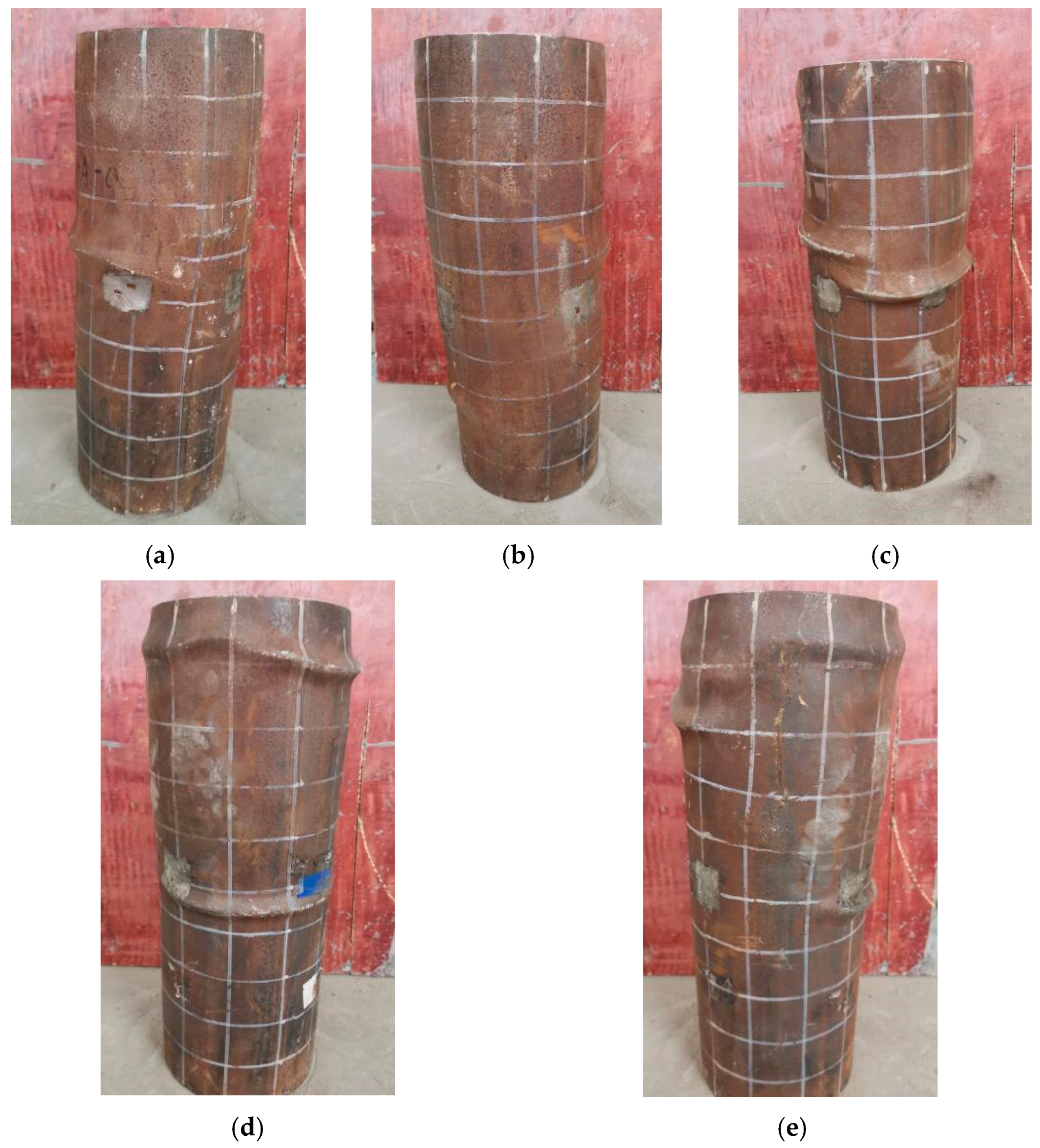
3.1.2. C30-3 Series Specimens

Figure 5 shows the final failure mode of the specimens with a concrete strength grade of C30 and a steel content of 4.24%. In the initial stage of loading, the load on each specimen increased linearly with compression deformation, and the surface changes of the steel pipe were not significant. With the increase in RSF content, the specimens began to show peeling and slag shedding, and the load values corresponding to deformation, bulging, and yield showed a significant upward trend overall. When the RSF content was 0%, 0.5%, 1.0%, 1.5%, and 2.0%, the corresponding load values for the occurrence of rust slag detachment on the steel surface were 830 kN (0.85 Nu), 730 kN (0.74 Nu), 820 kN (0.83 Nu), 840 kN (0.83 Nu), and 836 kN (0.8 Nu), respectively.
The load value at which the steel surface began to show obvious bulging exceeded 90% of the ultimate load, and the corresponding load values were 880 kN (0.91 Nu), 880 kN (0.91 Nu), 940 kN (0.95 Nu), 930 kN (0.92 Nu), and 960 kN (0.92 Nu), respectively. The ultimate load values of each specimen were 798 kN, 825 kN, 833 kN, 873 kN, and 905 kN, respectively. The maximum compression deformation of the specimen during unloading was 9 mm, 12.1 mm, 13.1 mm, 15.4 mm, and 18.1 mm, respectively. When the peak load was reached, the concrete inside the steel pipe broke and made a cracking sound. When there was obvious bulging when the specimen was damaged, the upper middle part of the specimen was more pronounced, while the lower half was not. The main form of damage to the five pillars was obvious drumbeat damage.

3.1.3. C50-2 Series Specimens

Figure 6 shows the final failure mode of the specimens with a concrete strength grade of C50 and a steel content of 2.84%. At the beginning of loading, the specimens were in an elastic working state, with a linear increase in load and deformation, and the force was uniform. At this time, the surface of the steel pipe did not change significantly. With the increase in RSF content, residual detachment, deformation bulging, and yield corresponding load values on the specimens began to show a slight downward trend. When the RSF content was 1.0% and 2.0%, the corresponding load values for rust and residue falling off the steel surface were 840 kN (0.78 Nu). The load value of the specimens with obvious bulging exceeded 90% of the ultimate load, and the corresponding load values were 970 kN (0.92 Nu) and 961 kN (0.90 Nu), respectively. The upper and middle parts of the specimens have obvious bulging, especially within a range of 10 cm from the loading end. The ultimate load values of each specimen were 1079 kN and 1045 kN, respectively. When the peak load was reached, the brittle sound of the concrete inside the steel pipe was obvious, and the failure mode of the two columns mainly showed obvious shear failure.
Through the analysis of the entire stress process of all specimens, the failure development process of STRSFRCSCs was shown to be different. In the initial stage of loading, when the loading load increased from zero to about 0.7 times the peak load (0.7 Nu), the deformation of all specimens changed proportionally with the continuous loading of the load, and the surface of the steel pipe did not show significant changes. In the subsequent loading process, due to the different steel content of the specimens, the lateral expansion constraint effect of the steel tube confined core concrete was inconsistent. The higher the steel content, the stronger was the constraint effect, and the development and final morphology of the specimens were different. When the concrete strength grade was C30 and the steel content was 2.84%, the specimens all exhibited shear failure. When the concrete strength grade was C30 and the steel content was 4.24%, the failure mode of the specimens was waist drum failure, but the deformation characteristics tended to develop towards shear failure. When the concrete strength grade was C50 and the steel content was 2.84%, the specimens all exhibited shear failure.
When the constraint of steel pipes on concrete is strengthened, the compressive strength and ductility of concrete will be improved. The presence of steel pipes limits the lateral expansion of concrete, allowing it to maintain higher integrity during compression. Under high constraint conditions, the failure mode of concrete transitions from brittle shear failure to ductile waist drum failure, with more uniform distribution of internal cracks. The core indicators of this destruction mechanism are the changes in the constitutive relationship of the material and the generation of the confinement effect. By analyzing the experimental results, it can be concluded that the volume fraction of RSF has little effect on the failure mode of the specimens at the same steel content and concrete strength grade.

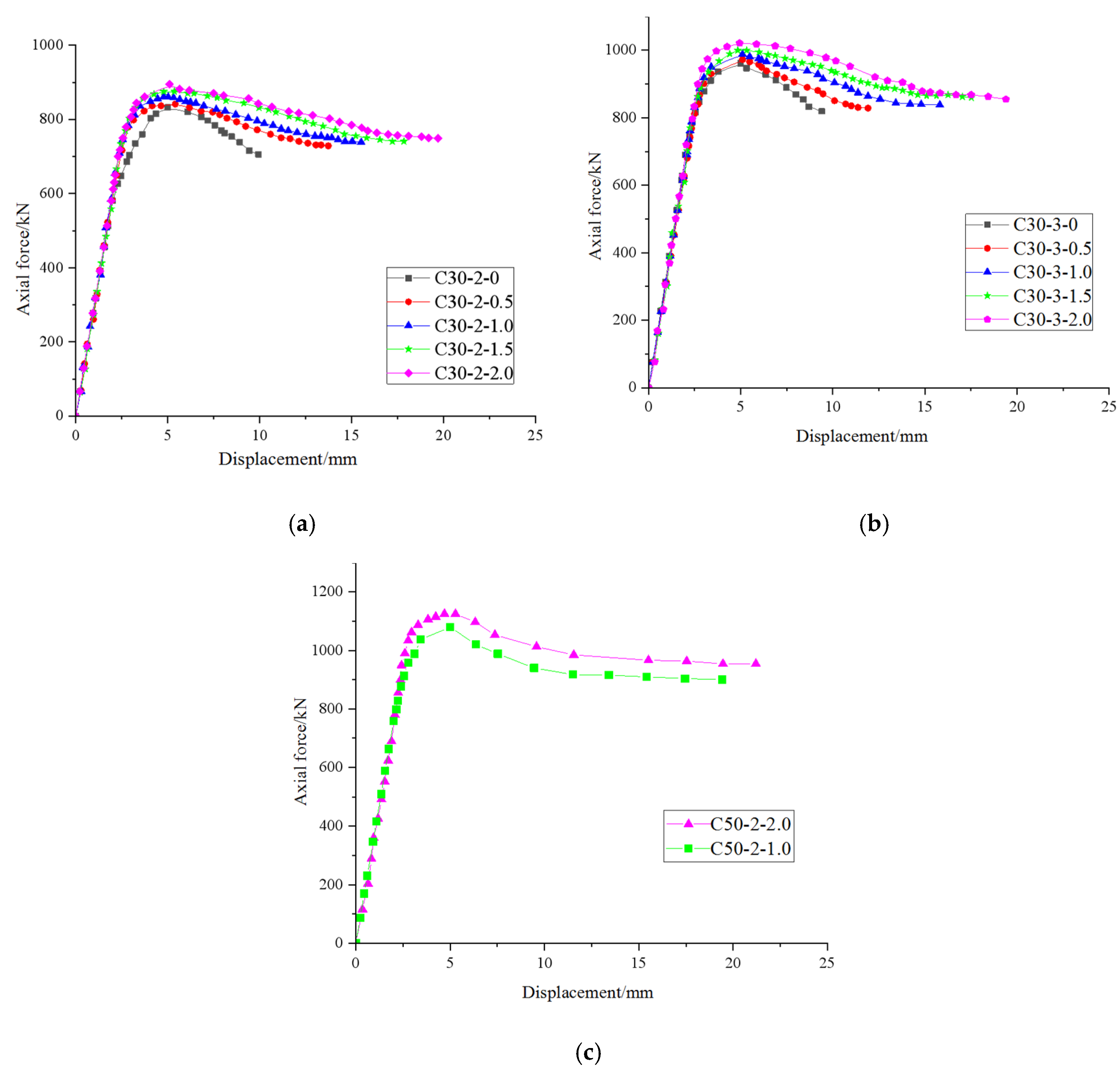
3.2. Load Deformation Curve

Figure 7 shows the load displacement curves of the STRSFRCSC axial compression test. It is obvious that STRSFRCSC is in the elastic stage as a whole in the early stage of loading, and the displacement shows a proportional change with the increase in load. The load when the specimen is in the elastic section is about 0.7 times the peak load, and then the load displacement curve begins to grow rapidly to reach the peak load, and the subsequent curve decreases gradually.
Compared with CFST specimens, the elastic stage of STRSFRCSC specimens is slightly longer, mainly because the addition of RSF can effectively limit the development of concrete cracks, improve the compressive strength of concrete, and enhance the ductility performance of concrete.
However, the difference is that when the concrete strength grade is C30, for specimens with steel pipe wall thicknesses of 2 mm and 3 mm, the higher the RSF content, the higher the peak load, and the longer the length of the curve after the peak load, indicating better ductility performance. When the RSF content is 2.0%, the maximum peak load of the specimen is increased by about 10% compared to CFST, but the maximum deformation value is doubled compared to CFST specimens. The peak load and maximum deformation of C50 concrete specimens are very close, that is, when the RSF content increases from 1.0% to 2.0%, the peak load increases by 3.1% and the maximum deformation increases by 12.6%.
When the steel content and concrete strength grade are the same, as the amount of RSF added to the core concrete increases, and the ductility and peak load of the specimen also show a gradually increasing trend. When the RSF content and concrete strength grade remain unchanged, the ultimate load of the specimen increases with the increase in steel content.
When the steel content and RSF volume fraction are the same, the specimen with a concrete strength grade of C50 has a much higher peak load than the specimen with a strength grade of C30. The peak load increases by 28%, but the maximum deformation is basically the same, both of which are about 24 mm. When the content of RSF is 2.0%, the contribution to the ductility of concrete may reach its limit.
In summary, with the increase in RSF content, the peel load value shows an upward trend, but after increasing to a certain extent, the peel load value decreases due to the deterioration of fiber dispersion. Moderate RSF can limit the propagation of microcracks inside concrete and improve its crack resistance; however, excessive RSF may increase the risk of concrete shrinkage and cracking, and instead reduce the expansion load value. RSF forms a mesh structure in concrete, which can effectively transmit and disperse stress, thereby enhancing the bearing capacity and toughness of concrete. With the increase in RSF content, the ultimate load value usually shows an upward trend. However, it is also important to note the impact of fiber dispersion on performance.

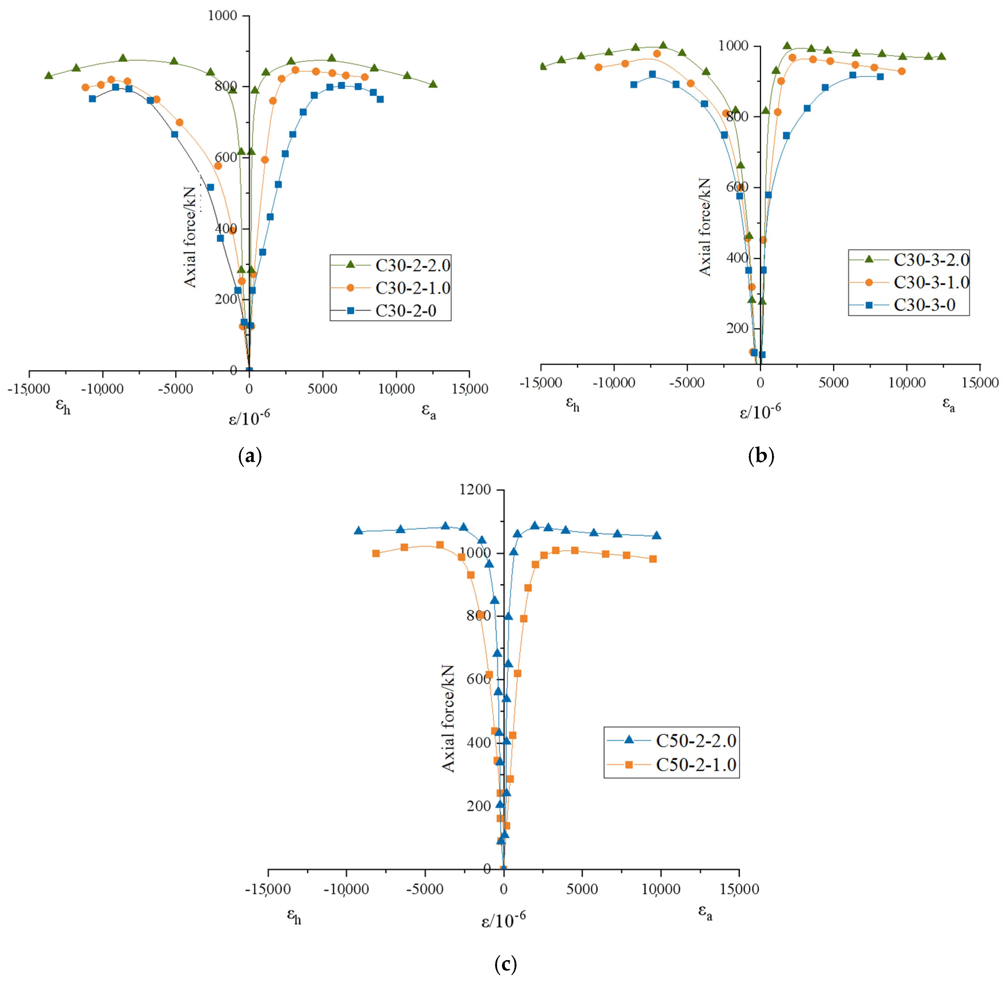
3.3. Load Strain Relationship

The load strain curves of the STRSFRCSC specimens are shown in Figure 8, where the abscissa represents the average measured effective strain in the middle of each specimen, with tension being positive (transverse strain) and compression being negative (longitudinal strain). The data collected from eight strain gauges arranged at four angles of 0°, 90°, 180°, and 270° in the middle of the specimen height were filtered out to obtain effective data. Then, the arithmetic mean was calculated according to different types of pasting directions, and the longitudinal and transverse strains of RSF reinforced concrete filled steel tubes were finally obtained.
Figure 8 shows that all specimens are in the elastic stage as a whole during the initial loading stage, and the strain shows a proportional change with the increase in load, at which point the strain growth rate is slow. As the loading continues to reach about 0.7 times the peak load, the specimens enter a stage of nonlinear variation, and the RSF in the concrete core area begins to fail to suppress the development of cracks. Cracks begin to appear in the core concrete, and plastic deformation begins to occur in the steel pipe. The surface strain of the specimens increases rapidly, and a clear turning point appears in the curves.
Compared with CFST, the lateral ultimate strain of STRSFRCSC increases, and the corresponding lateral stress of the specimen changes less at peak load. When the RSF content and concrete strength grade are the same, when the specimen reaches the peak load, the lateral strains of specimens C30-3-0 and C30-3-1.0 are 0.00614 and 0.00218, respectively, while the lateral strains of C30-2-0 and C30-2-1.0 are 0.0647 and 0.00313, respectively. The lateral strains of high-strength concrete specimens C50-2-1.0 and C50-2-2.0 are 0.00248 and 0.00211, respectively.
In summary, with the increase in RSF content, the transverse strain corresponding to the peak load of the specimens decreases, and the lower the steel content, the more significant is the influence of RSF on the transverse strain. The influence of RSF content on the longitudinal strain of the specimens is not significant, and the longitudinal strain corresponding to the peak load of the three types of specimens is around 0.072.

3.4. Lateral Deformation Coefficient

Figure 9 shows the variation curves of the transverse deformation coefficient of STRSFRCSC specimens with stress, reflecting the interaction relationship between different materials. The nominal stress is the ratio of the loading load at a certain moment to the total area of the specimen.
From Figure 9, it can be concluded that during the initial stage of load loading, the overall deformation of the specimens is in the elastic stage, and the lateral deformation coefficient fluctuates around 0.29, which is close to Poisson’s ratio (0.3) of the raw material. As the load continues to increase, the specimens enter a stage of nonlinear variation, and microcracks inside the core concrete begin to develop, causing compression on the steel pipe, and the lateral expansion of the specimens begins to manifest. When the concrete strength grade and RSF content are the same, as the wall thickness increases from 2 mm to 3 mm, reaching 60% and 70% of the ultimate stress, the lateral deformation coefficient of the specimens begins to show a significant increase. This is because the increase in the steel content of the specimens enhances the constraint effect of the steel pipe on the core concrete.
When the specimens enter the elastic–plastic deformation stage, as the volume fraction of RSF increases, the slope of the lateral deformation coefficient growth rate is roughly equal, and the corresponding lateral deformation coefficient decreases when reaching the peak load. This is because RSF is added to the core concrete, and the bridging effect of RSF hinders the further development of microcracks inside the concrete, delaying the lateral expansion of the core concrete, thereby reducing the lateral strain under ultimate load and reducing the lateral deformation coefficient. For the C30-3-0.5 specimen, under peak load, its lateral deformation expansion is significant, and the lateral deformation coefficient at this time is 0.5. The addition of steel fibers can suppress the development of microcracks inside concrete, enhance the bonding stress between the internal interfaces of concrete, and thus improve the mechanical properties of concrete. Under the action of load, RSF will be pulled out or pulled apart as cracks develop, which consumes a large amount of energy and delays the failure process of concrete, enhancing its toughness performance. If we want to explore the working mechanism of RSF in detail, we need to use SEM technology to reveal it.
When the wall thickness and steel fiber content are the same, as the concrete strength increases, the transverse deformation system rapidly increases when the specimens enter the elastic–plastic stage.

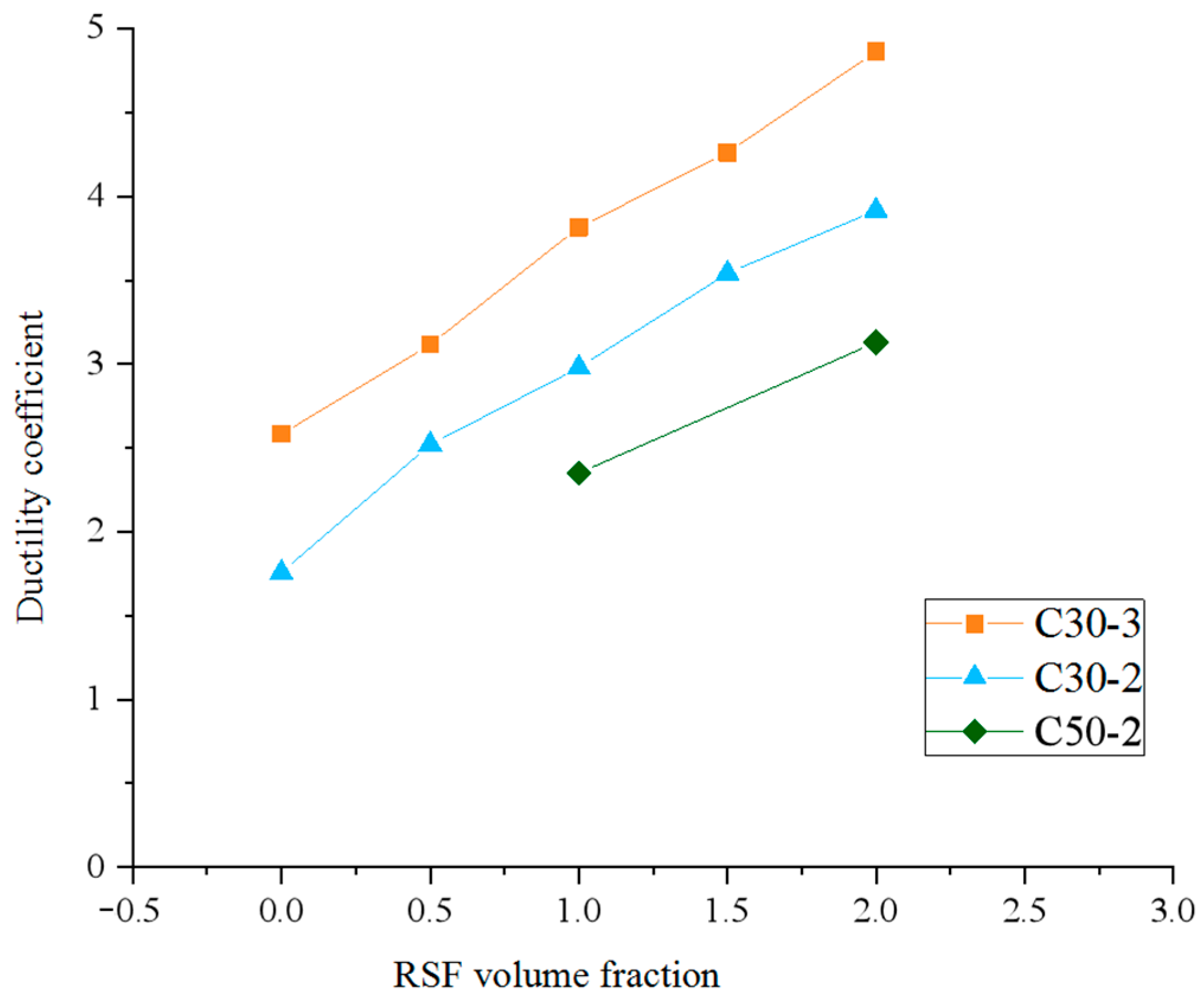
3.5. Ductility Performance

Ductility is particularly important in performance-based engineering seismic design. Improving the ductility of components in the plastic energy dissipation zone of structural design can enhance their energy dissipation capacity, reduce structural damage caused by earthquake action, and reduce the probability of brittle failure. The ductility calculation formula based on existing literature is shown in (1) [64]:
μ = Δ u 85 % Δ u
The displacement corresponding to the peak load in the equation is 85% of the displacement corresponding to the peak load in the descending section.
The influence of different steel content, waste steel fiber content, and concrete strength grade on the ductility of short column specimens can be determined by Equation (1), as shown in Figure 10. As shown in Figure 10, for the C30-3 series specimens, the ductility coefficient is 2.58 when the steel fiber content is 0, 3.12 when the content is 0.5%, 3.83 when the content is 1.0%, 4.26 when the content is 1.5%, and 4.86 when the content is 2.0%. The ductility coefficient of specimen C30-3-2.0 increased by 188.4% compared to C30-3-0.
From the analysis of experimental results, it can be concluded that when the concrete strength grade is C30 and the steel pipe wall thickness is 2 mm and 3 mm, the ductility coefficient of STRSFRCSCs gradually increases with the increase in steel fiber volume fraction. Under the same other parameters, as the strength grade of concrete increases, the ductility of the specimens shows a downward trend, mainly due to the increase in the strength of the core concrete, which increases its brittleness and deteriorates its ductility. If the RSF content and concrete strength grade remain unchanged, the ductility of the specimens significantly increases with the increase in steel content, mainly due to the increase in the cross-sectional area of the steel pipe and the improvement of plastic deformation capacity.

3.6. Combined Elastic Modulus

According to the unified theory of steel tube concrete, the two materials (steel tube and concrete) are equivalent to a single material, and their combined elastic modulus is studied by analyzing the overall specimen, represented by Esc [65]. The specific calculation formulas are as follows:
E s c = σ ε
σ = N A c + A s
In these equations, σ is the combined stress at the elastic stage, ε is the corresponding strain at the elastic stage, N is the axial force at the elastic stage, Ac is the cross-sectional area of the concrete, and As is the cross-sectional area of the steel pipe.
According to the results of the load displacement curve, it can be seen that when the specimens are in the linear variation stage, the maximum load applied is about 0.7 times the ultimate load. The initial data of the linear variation in the elastic stage are used to study the combined elastic modulus of STRSFRCSCs. The calculated values of the elastic modulus of each specimen are shown in Table 5.
Figure 11 shows the effect of different parameters on the elastic modulus of the STRSFRCSC combination. It can be clearly seen from the graph that, under the condition of constant concrete strength grade and steel pipe wall thickness, as the RSF volume fraction increases, the combined elastic modulus of the specimens shows a slow upward trend, but the magnitude of the increase can be ignored.
Under the condition of constant concrete strength grade and RSF content, when the steel content of the specimen increases by 1.4%, its combined elastic modulus significantly increases. Compared with specimen C30-2-1.0, the wall thickness of specimen C30-3-1.0 increases by 1 mm, and the combined elastic modulus of the specimen increases from 39,690 N/mm2 to 44,123 N/mm2. The main reason is that as the steel content of the specimen increases, the cross-sectional area of the steel pipe also increases, which strengthens the constraint ability of the steel pipe on the concrete in the core area, increases the ultimate strength of the core concrete, and thus improves the composite elastic modulus of the column.
When the wall thickness of the steel pipe is 2 mm and the RSF content is 1.0% and 2.0%, the strength grade of the concrete ranges from C30 to C50, and the combined elastic modulus of the specimens is also slightly improved. The main reason is that the higher the strength grade of the concrete raw materials themselves, the greater is their elastic modulus.

3.7. Axial Compressive Bearing Capacity

3.7.1. Factors Affecting Axial Compressive Bearing Capacity

Through the analysis of axial compression test results, it was found that the volume fraction of RSF, steel content, and concrete strength grade all have an impact on the bearing capacity of STRSFRCSCs. Figure 12 shows the magnitude of the influence of three different parameters on the bearing capacity of STRSFRCSCs. Overall, the bearing capacity of columns increases with the increase in RSF volume fraction, steel content, and concrete strength.
As the volume fraction of RSF increases, the ultimate bearing capacity of the specimens increases to a certain extent, with a maximum increase of 13.4%. The main reason is that the three-dimensional form of RSF forms a spatial skeleton in the concrete, and the bridging effect weakens the development of concrete cracks inside the core area, forming micro-reinforced concrete structures in the concrete, thereby improving the bearing capacity of the specimens. According to Figure 12a, compared with specimen C30-2-0, the ultimate bearing capacity of specimens C30-2-0.5, C30-2-1.0, C30-2-1.5, and C30-2-2.0 increases by 3.4%, 4.4%, 9.4%, and 13.4%, respectively.
When the RSF content and concrete strength grade remain unchanged, the steel content of the specimen increases from 2.84% to 4.24%, and its bearing capacity also shows a significant increase. This is due to the increase in the cross-sectional area of the test steel pipe, which enhances the restraining effect of the steel pipe on the concrete in the core area, enhances the hoop effect of the steel pipe on the concrete, and thus improves the ultimate bearing capacity of the concrete. According to Figure 12c, as the RSF content increases from 0.5% to 2.0%, the growth rates of the bearing capacity of the specimens are 18.8%, 18.6%, 15.5%, and 15.5%, respectively, with an average increase of 17.1%.
When the steel content and RSF volume fraction remain unchanged, the overall bearing capacity of STRSFRCSC specimens improves with the increase in concrete strength. As shown in Figure 12d, the ultimate bearing capacity of specimen C50-2-1.0 increases by 29.5% compared to specimen C30-2-1.0.

3.7.2. Calculation Method for Axial Compressive Bearing Capacity

The ultimate bearing capacity of STRSFRCSCs under axial compression can be divided into two parts: steel pipe and RSF concrete in the core area. Due to their mutual interaction, their ultimate bearing capacity is significantly improved. The calculation formula for the axial compressive bearing capacity of STRSFRCSCs needs to consider the following two factors: firstly, when RSF is not added, its ultimate bearing capacity calculation formula can degenerate into the calculation formula for ordinary steel tube concrete short columns; secondly, when adding RSF, the calculation formula for its bearing capacity needs to reflect the influence of RSF volume dosage.
Referring to existing research results and considering the influence of RSF volume fraction on the bearing capacity of specimens, the influence of steel fiber parameters is introduced by modifying the specification formula to establish the axial compressive ultimate bearing capacity formula of STRSFRCSCs [66,67], as shown in Formula (4):
N u = A c f c 1 + 1.8 ϕ + α γ f
In the equation, Ac is the cross-sectional area of the core concrete (mm2), fc is the axial compressive strength of the core concrete (MPa), φ is the confinement coefficient, φ = (Asfy)/(Acfc). The coefficient of influence on RSF, α, is the characteristic value of steel fiber content, taking into account the influence of factors such as RSF type, dosage, and aspect ratio on the crack resistance of concrete, γf = (ρflf)/df; when γf > 1.2, it is taken as 1.2. The characteristic values of RSF content in this experiment are shown in Table 6. ρf is the volume percentage of RSF, df is the diameter of RSF, and lf is the length of RSF.
By conducting regression analysis on the bearing capacity test values of ten STRSFRCSCs in this study, the RSF influence coefficient α was obtained to be 0.2. This was incorporated into Equation (4) to obtain the ultimate bearing capacity Equation (5) for the columns:
N u = A c f f 1 + 1.8 ϕ + 0.2 γ f
Table 7 shows the ratio of the calculated and experimental values of the STRSFRCSC bearing capacity. According to Equation (5), the calculated values of the bearing capacity of each specimen are obtained. The average value of the ratio is 1.0085, the mean square error is 0.017, and the coefficient of variation is 0.012.

4. Conclusions

By conducting axial compression tests on STRSFRCSCs, the influence of failure modes, load strain curves, load displacement curves, combined elastic modulus, ductility, etc. of the specimens was analyzed, and a formula for calculating the axial compression bearing capacity of STRSFRCSCs was established. The main research conclusions are as follows:
(1)
The influence of steel content on the failure mode of STRSFRCSC is significant. When the steel content is 2.84%, the specimens are subjected to shear failure. When the steel content is 4.24%, the specimens are subjected to waist drum failure, which tends to transition to shear failure. The influence of concrete strength grade and RSF content on the failure mode of specimens is not significant.
(2)
The higher the steel content and concrete strength grade, the higher is the ultimate bearing capacity and composite elastic modulus of the specimens. The optimal RSF is 2%, and the maximum increase in the bearing capacity of STRSFRCSCs is 13.4%. As the RSF content increases, the peak strain during the loading process of the specimens decreases and the combined elastic modulus increases.
(3)
The addition of RSF significantly improves ductility. As the volume fraction of RSF increases, the ductility coefficient of the specimens gradually increases. As the steel content increases, its bearing capacity and displacement ductility coefficient both increase. As the strength grade of concrete increases, the bearing capacity of the column increases, but the displacement ductility coefficient shows a decreasing trend.
(4)
On the basis of existing research results and combined with experimental data, the influence of RSF volume fraction on the bearing capacity of specimens was considered, and the calculation formula for the axial compressive bearing capacity of STRSFRCSCs was obtained through regression analysis. By comparing and analyzing the experimental data, it is shown that the calculated results of this formula are in good agreement with the experimental results, with a low degree of dispersion and a concise calculation method, which can effectively predict the ultimate bearing capacity of STRSFRCSCs under axial compression.
(5)
This study only conducted axial compression tests on STRSFRCSCs, and a comparison of bearing capacity with similar components made of native steel fibers has not been conducted yet. Compression bending tests, bending tests, and shear tests of STRSFRCSCs have not yet been carried out, and these are all future research directions.

Author Contributions

Conceptualization, M.T.; methodology, Y.G.; software, X.H.; validation, H.Z.; formal analysis, B.W.; investigation, B.W.; resources, H.L.; data curation, B.W.; writing—original draft preparation, N.D.; writing—review and editing, X.Z. All authors have read and agreed to the published version of the manuscript.

Funding

This research was funded by the Jiangxi Province Intelligent Building Engineering Research Center Open Fund Project (No. HK20231009), the National Natural Science Foundation of China, and the State Key Laboratory of Geological Disaster Prevention and Geological Environmental Protection of Chengdu University of Technology, grant numbers 2015BAK09B01, 41877273, and SKLGP2019K019.

Data Availability Statement

Data will be made available upon request.

Acknowledgments

The authors thank the editors and reviewers for their guidance and feedback on the paper.

Conflicts of Interest

The authors declare that they have no known competing financial interests or personal relationships that could have appeared to influence the work reported in this paper.

References

  1. Li, X.Z.; Zhang, S.M.; Lu, W.; Li, J. Axial compressive behavior of steel-tube-confined concrete-filled-steel-tubes. Thin-Walled Struct. 2022, 181, 110138. [Google Scholar] [CrossRef]
  2. Zhu, T.; Liang, H.J.; Lu, Y.Y.; Li, W.J.; Zhang, H. Axial behaviour of slender concrete-filled steel tube square columns strengthened with square concrete-filled steel tube jackets. Adv. Struct. Eng. 2020, 23, 1074–1086. [Google Scholar] [CrossRef]
  3. Khalifa, M.; Shaat, A.; Ibrahim, S. Optimum concrete filling ratio for partially filled noncompact steel tubes. Thin-Walled Struct. 2019, 134, 159–173. [Google Scholar] [CrossRef]
  4. Zhang, T.H.; Wang, Y.H.; Zhai, X.M.; Zhi, X.D.; Zhou, H.Y.; Yu, X. Impact response of stainless steel tube locally-strengthened by concrete-filled steel tube. Int. J. Impact Eng. 2024, 186, 104895. [Google Scholar] [CrossRef]
  5. Hosseinzadehfard, E.; Mobaraki, B. Investigating concrete durability: The impact of natural pozzolan as a partial substitute for microsilica in concrete mixtures. Constr. Build. Mater. 2024, 419, 135491. [Google Scholar] [CrossRef]
  6. Alatshan, F.; Osman, S.A.; Hamid, R.; Mashiri, F. Stiffened concrete-filled steel tubes: A systematic review. Thin-Walled Struct. 2018, 148, 106590. [Google Scholar] [CrossRef]
  7. Abed, F.H.; Abdelmageed, Y.I.; Ilgun, A.K. Flexural response of concrete-filled seamless steel tubes. J. Constr. Steel Res. 2021, 149, 53–63. [Google Scholar] [CrossRef]
  8. Zheng, J.L.; Wang, J.J. Concrete-filled steel tube arch bridges in China. Engineering 2018, 4, 143–155. [Google Scholar] [CrossRef]
  9. Ahmad, S.; Kumar, A.; Kumar, K. Axial performance of GGBFS concrete filled steel tubes. Structures 2020, 23, 539–550. [Google Scholar] [CrossRef]
  10. Ahmad, H.S.; Abendeh, R.M.; Hunaiti, Y.M. Evaluation of concrete-steel interfaces in steel tubes filled with chipped rubber-concrete. Proc. Inst. Civ. Eng.-Struct. Build. 2023, 176, 91–113. [Google Scholar] [CrossRef]
  11. Xu, X.; Cheng, R.; Yang, P.; Liu, R.Q. Cyclic Loading Test for Concrete-Filled U-Shaped Steel Beam to Concrete-Filled Steel Tube Column Connections. Int. J. Steel Struct. 2020, 20, 1859–1870. [Google Scholar] [CrossRef]
  12. Shen, P.L.; Lu, J.X.; Zheng, H.B.; Lu, L.N.; Wang, F.Z.; He, Y.J.; Hu, S.G. Expansive ultra-high performance concrete for concrete-filled steel tube applications. Cem. Concr. Compos. 2020, 114, 103813. [Google Scholar] [CrossRef]
  13. Ding, C.T.; Pan, X.B.; Bai, Y.; Shi, G. Prefabricated connection for steel beam and concrete-filled steel tube column. J. Constr. Steel Res. 2019, 162, 105751. [Google Scholar] [CrossRef]
  14. Elghazouli, A.Y.; Mujdeci, A.; Bompa, D.V.; Guo, Y.T. Experimental cyclic response of rubberised concrete-filled steel tubes. J. Constr. Steel Res. 2022, 199, 107622. [Google Scholar] [CrossRef]
  15. Krishan, A.L.; Astafeva, M.A.; Chernyshova, E.P. Strength Calculation of Short Concrete-filled Steel Tube Columns. Int. J. Concr. Struct. Mater. 2019, 12, 84. [Google Scholar] [CrossRef]
  16. Li, W.T.; Zha, X.X.; Wang, H.Y. A unified formulation for axial compression of steel tube-confined concrete and concrete-filled steel tube stub columns. Structures 2023, 58, 105319. [Google Scholar] [CrossRef]
  17. Kanishchev, R.; Kvocak, V. Local buckling of rectangular steel tubes filled with concrete. Steel Compos. Struct. 2019, 31, 201–216. [Google Scholar]
  18. Ekmekyapar, T.; Al-Eliwi, B.J.M. Concrete filled double circular steel tube (CFDCST) stub columns. Eng. Struct. 2017, 135, 68–80. [Google Scholar] [CrossRef]
  19. Mobaraki, B.; Ma, H.Y.; Galant, J.A.L.; Turmo, J. Structural Health Monitoring of 2D Plane Structures. Appl. Sci. 2021, 11, 2000. [Google Scholar] [CrossRef]
  20. Li, X.Z.; Zhang, S.M.; Tao, Y.; Zhang, B. Numerical Study on the Axial Compressive Behavior of Steel-Tube-Confined Concrete-Filled Steel Tubes. Materials 2024, 17, 155. [Google Scholar] [CrossRef]
  21. Wang, S.Y.; Wang, W.; Xie, Z.Y. Nonlinear cyclic behavior of steel tube in concrete-filled steel tube members including local buckling. Thin-Walled Struct. 2023, 191, 111055. [Google Scholar] [CrossRef]
  22. Wei, Y.; Zhu, C.; Miao, K.T.; Zheng, K.Q.; Tang, Y. Compressive performance of concrete-filled steel tube columns with in-built seawater and sea sand concrete-filled FRP tubes. Constr. Build. Mater. 2022, 317, 125933. [Google Scholar] [CrossRef]
  23. Ye, Y.; Li, W.; Liu, X.J.; Guo, Z.X. Behaviour of concrete-filled steel tubes with concrete imperfection under axial tension. Mag. Concr. Res. 2021, 73, 743–756. [Google Scholar] [CrossRef]
  24. Skalomenos, K.A.; Hayashi, K.; Nishi, R.; Inamasu, H.; Nakashima, M. Experimental Behavior of Concrete-Filled Steel Tube Columns Using Ultrahigh-Strength Steel. J. Struct. Eng. 2016, 14, 04016057. [Google Scholar] [CrossRef]
  25. Liu, Z.N.; Lu, Y.Y.; Li, S.; Liao, J.C. Shear response of steel fiber reinforced recycled concrete-filled steel tube columns. Adv. Struct. Eng. 2021, 24, 2684–2704. [Google Scholar] [CrossRef]
  26. Dai, P.; Yang, L.; Wang, J.; Fan, J.W.; Lin, M.F. Experimental study on the steel-concrete bond behaviour of circular concrete-filled stainless steel tubes. Thin-Walled Struct. 2021, 169, 108506. [Google Scholar] [CrossRef]
  27. Wang, Z.B.; Zhang, J.B.; Li, W.; Wu, H.J. Seismic performance of stiffened concrete-filled double skin steel tubes. J. Constr. Steel Res. 2020, 169, 106020. [Google Scholar] [CrossRef]
  28. Lin, S.C.; Liu, F.B.; Bai, Q. Bond Behavior of Concrete-Filled Steel Tube with Molybdenum Tailing. Int. J. Steel Struct. 2024, 24, 354–365. [Google Scholar] [CrossRef]
  29. Roeder, C.W.; Stephens, M.T.; Lehman, D.E. Concrete Filled Steel Tubes for Bridge Pier and Foundation Construction. Int. J. Steel Struct. 2018, 18, 39–49. [Google Scholar] [CrossRef]
  30. Alhussainy, F.; Sheikh, M.N.; Hadi, M.N.S. Behaviour of small-diameter self-compacting concrete-filled steel tubes. Mag. Concr. Res. 2018, 70, 811–821. [Google Scholar] [CrossRef]
  31. Zhang, Y.T.; Shan, B.; Xiao, Y. Axial impact behaviors of stub concrete-filled square steel tubes. Adv. Struct. Eng. 2019, 22, 2490–2503. [Google Scholar] [CrossRef]
  32. Dong, M.H.; Elchalakani, M.; Karrech, A.; Fawzia, S.; Ali, M.S.M.; Yang, B.; Xu, S.Q. Circular steel tubes filled with rubberised concrete under combined loading. J. Constr. Steel Res. 2019, 162, 105613. [Google Scholar] [CrossRef]
  33. Liu, Z.Z.; Ma, X.X.; Li, N.; Chen, J.; Lu, Y.Y. Research advances in fiber-reinforced concrete-filled steel tube columns. Struct. Des. Tall Spec. Build. 2024, e2155. [Google Scholar] [CrossRef]
  34. Samingthong, W.; Hoy, M.; Ro, B.; Horpibulsuk, S.; Yosthasaen, T.; Suddeepong, A.; Yaowarat, T.; Arulrajah, A. Natural Rubber Latex-Modified Concrete with PET and Crumb Rubber Aggregate Replacements for Sustainable Rigid Pavements. Sustainability 2023, 15, 14147. [Google Scholar] [CrossRef]
  35. Sengul, O. Mechanical properties of slurry infiltrated fiber concrete produced with waste steel fibers. Constr. Build. Mater. 2018, 186, 1082–1091. [Google Scholar] [CrossRef]
  36. George, C.; Selvan, S.S.; Kumar, V.S.; Murali, G.; Giri, J.; Makki, E.; Sathish, T. Enhancing the fire-resistant performance of concrete-filled steel tube columns with steel fiber-reinforced concrete. Case Stud. Constr. Mater. 2024, 20, e02741. [Google Scholar] [CrossRef]
  37. Domski, J.; Zakrzewski, M. Deflection of Steel Fiber Reinforced Concrete Beams Based on Waste Sand. Materials. 2020, 13, 392. [Google Scholar] [CrossRef] [PubMed]
  38. Zeybek, O.; Özkilic, Y.O.; Çelik, A.I.; Deifalla, A.F.; Ahmad, M.; Sabri, M.M.S. Performance evaluation of fiber-reinforced concrete produced with steel fibers extracted from waste tire. Front. Mater. 2022, 9, 1057128. [Google Scholar] [CrossRef]
  39. Ojeda, J.P.; Mercante, I.T.; de Borbón, F.M.; Zerbino, R.; Torrijos, M.C.; Giaccio, G. Pull-out performance of plastic and steel fibers recycled from waste. J. Reinf. Plast. Compos. 2024. [Google Scholar] [CrossRef]
  40. Gok, S.G.; Sengul, O. The effect of recycled waste glass as a coarse aggregate on the properties of portland cement concrete and geopolymer concrete. Constr. Build. Mater. 2023, 408, 133697. [Google Scholar] [CrossRef]
  41. Yan, J.Q.; Gao, Y.T.; Tang, M.G.; Ding, N.S.; Xu, Q.; Peng, M.; Zhao, H. Experimental Study on the Mechanical Properties of Recycled Spiral Steel Fiber-Reinforced Rubber Concrete. Buildings 2024, 14, 897. [Google Scholar] [CrossRef]
  42. Yan, J.Q.; Gao, Y.T.; Fan, T.; Xu, Q.; Yuan, W.G.; Zhao, X. Experimental Study on Flexural Performance of Recycled Steel Fiber Concrete Beams. Buildings 2023, 13, 3046. [Google Scholar] [CrossRef]
  43. Akça, K.R.; Ipek, M.; Çelenk, S.; Karabulak, A. Experimental investigation on mechanical properties of HSSCC containing waste steel fibers obtained from end-of-life tires. Rev. Constr. 2023, 22, 87–101. [Google Scholar]
  44. Lehmann, M.; Glodkowska, W. Shear Capacity and Behaviour of Bending Reinforced Concrete Beams Made of Steel Fibre-Reinforced Waste Sand Concrete. Materials 2021, 14, 2996. [Google Scholar] [CrossRef] [PubMed]
  45. Dezhampanah, S.; Nikbin, I.M.; Charkhtab, S.; Fakhimi, F.; Bazkiaei, S.M.; Mohebbi, R. Environmental performance and durability of concrete incorporating waste tire rubber and steel fiber subjected to acid attack. J. Clean. Prod. 2020, 268, 122216. [Google Scholar] [CrossRef]
  46. Deng, Z.M. Utilisation of steel fibres to reinforce waste glass concrete: Alkali-silica reaction, engineering properties, and 3D mesoscale modelling. Case Stud. Constr. Mater. 2022, 17, e01686. [Google Scholar] [CrossRef]
  47. Smrkic, M.F.; Damjanovic, D.; Baricevic, A.; Uros, M. Experimental and numerical analysis of concrete slabs reinforced with rebar and recycled steel fibers from waste car tyres. Struct. Concr. 2023, 24, 1807–1820. [Google Scholar] [CrossRef]
  48. Althoey, F.; Zaid, O.; Alsharari, F.; Yosri, A.M.; Isleem, H.F. Evaluating the impact of nano-silica on characteristics of self-compacting geopolymer concrete with waste tire steel fiber. Arch. Civ. Mech. Eng. 2022, 23, 48. [Google Scholar] [CrossRef]
  49. Fakoor, M.; Nematzadeh, M. Evaluation of post-fire pull-out behavior of steel rebars in high-strength concrete containing waste PET and steel fibers: Experimental and theoretical study. Constr. Build. Mater. 2021, 299, 123917. [Google Scholar] [CrossRef]
  50. Abbas, S. Preventive measures of Alkali-Silica Reaction in concrete buildings: Use of hybrid waste coal ash and steel wire cut fibers. Buildings 2023, 13, 710. [Google Scholar] [CrossRef]
  51. Chen, M.; Sun, J.Q.; Zhang, T.; Shen, Y.; Zhang, M.Z. Enhancing the dynamic splitting tensile performance of ultra-high performance concrete using waste tyre steel fibres. J. Build. Eng. 2023, 80, 108102. [Google Scholar] [CrossRef]
  52. Nematzadeh, M.; Karimi, A.; Fallah-Valukolaee, S. Compressive performance of steel fiber-reinforced rubberized concrete core detached from heated CFST. Constr. Build. Mater. 2020, 239, 117832. [Google Scholar] [CrossRef]
  53. Liang, W.; Dong, J.F.; Wang, Q.Y. Axial compressive behavior of concrete-filled steel tube columns with stiffeners. Steel Compos. Struct. 2018, 29, 151–159. [Google Scholar]
  54. Guler, S.; Lale, E.; Aydogan, M. Non-linear analysis of steel fibre reinforced concrete-filled steel tube columns. Proc. Inst. Civ. Eng.-Struct. Build. 2013, 166, 298–306. [Google Scholar] [CrossRef]
  55. Jegadesh, J.S.S.; Jayalekshmi, S. Using fibres and fly ash in concrete-filled steel tube columns. Proc. Inst. Civ. Eng.-Struct. Build. 2016, 169, 741–755. [Google Scholar] [CrossRef]
  56. Miao, K.T.; Wei, Y.; Dong, F.H.; Zheng, K.Q.; Wang, J.Q. Experimental study on concrete-filled steel tube columns with inner distributed seawater and sea sand concrete-filled fiber-reinforced polymer tubes under axial compression. Compos. Struct. 2023, 320, 117181. [Google Scholar] [CrossRef]
  57. Xiong, Y.M.; Yang, M.; Yang, M.; Shi, H.; Zhao, J.K.; Yuan, Y.; Guo, X.Y. Axial compression behavior of concrete-filled prefabricated aligned steel fiber UHPC tubes. J. Build. Eng. 2024, 89, 109353. [Google Scholar] [CrossRef]
  58. Lu, Y.Y.; Li, N.; Li, S.; Liang, H.J. Behavior of steel fiber reinforced concrete-filled steel tube columns under axial compression. Constr. Build. Mater. 2015, 95, 74–85. [Google Scholar] [CrossRef]
  59. Huang, Y.; Zhao, P.T.; Lu, Y.Y.; Liu, Z.Z. Hysteresis performance of steel fiber-reinforced high-strength concrete-filled steel tube columns. J. Constr. Steel Res. 2024, 219, 108755. [Google Scholar] [CrossRef]
  60. GB/T51446-2021; Technical Standard for Concrete-Filled Steel Tubular Hybrid Structures. China Architecture & Building Press: Beijing, China, 2021. (In Chinese)
  61. GB50936-2014; Technical Code for Concrete Filled Steel Tubular Structures. China Architecture & Building Press: Beijing, China, 2021. (In Chinese)
  62. Anas, S.M.; Alam, M.; Umair, M. Experimental and numerical investigations on performance of reinforced concrete slabs under explosive-induced air-blast loading: A state-of-the-art review. Structures 2021, 31, 428–461. [Google Scholar] [CrossRef]
  63. Liu, Z.Z.; Lu, Y.Y.; Li, S.; Zong, S.; Yi, S. Flexural behavior of steel fiber reinforced self-stressing recycled aggregate concrete-filled steel tube. J. Clean. Prod. 2020, 274, 122724. [Google Scholar] [CrossRef]
  64. Li, J.T.; Chen, Z.P.; Xu, J.J.; Jing, C.G.; Xue, J.Y. Cyclic behavior of concrete-filled steel tubular column-reinforced concrete beam frames incorporating 100% recycled concrete aggregates. Adv. Struct. Eng. 2018, 21, 1802–1814. [Google Scholar] [CrossRef]
  65. Chen, J.; Kuder, K.G.; Lehman, D.E.; Roeder, C.W.; Lowes, L.N. Creep modeling of concretes with high volumes of supplementary cementitious materials and its application to concrete-filled tubes. Mater. Struct. 2017, 50, 89. [Google Scholar] [CrossRef]
  66. Xu, C.Y.; Han, L.H.; Hou, C. Behaviour of recycled aggregate concrete-filled stainless steel tubular columns subjected to lateral monotonic and cyclic loading. Eng. Struct. 2023, 293, 116663. [Google Scholar] [CrossRef]
  67. Zhao, H.Y.; Han, L.H.; Hou, C.; Lyu, W.Q. Performance of recycled aggregate concrete-filled high-strength steel tubes under axial compression, tension and torsion. Thin-Walled Struct. 2023, 184, 110478. [Google Scholar] [CrossRef]
Figure 1. Recycled steel fiber (RSF) raw materials. (a) RSF formation process; (b) RSF appearance.
Buildings 14 02498 g001
Figure 2. Sample fabrication and maintenance. (a) Steel pipe fixation; (b) mixing of RSF reinforced concrete; (c) curing of specimens.
Buildings 14 02498 g002
Figure 3. Loading device and measurement point layout. (a) Placement of test specimens; (b) strain data acquisition instrument; (c) arrangement of strain gauges and displacement gauges.
Buildings 14 02498 g003
Figure 4. Failure morphology of C30-2 series specimens: (a) C30-2-0; (b) C30-2-0.5; (c) C30-2-1.0; (d) C30-2-1.5; (e) C30-2-2.0.
Buildings 14 02498 g004
Figure 5. Failure morphology of C30-3 series specimens: (a) C30-3-0; (b) C30-3-0.5; (c) C30-3-1.0; (d) C30-3-1.5; (e) C30-2-2.0.
Buildings 14 02498 g005
Figure 6. Failure morphology of C50-2 series specimens: (a) C50-2-1.0; (b) C50-2-2.0.
Buildings 14 02498 g006
Figure 7. Load deformation curves for (a) C30-2 series specimens, (b) C30-3 series specimens, and (c) C50-2 series specimens.
Buildings 14 02498 g007
Figure 8. Load strain curves of (a) C30-2 series specimens, (b) C30-3 series specimens, and (c) C50-2 series specimens.
Buildings 14 02498 g008
Figure 9. Lateral deformation coefficient. (a) RSF dosage remains unchanged; (b) RSF dosage changes.
Buildings 14 02498 g009
Figure 10. Ductility performance.
Buildings 14 02498 g010
Figure 11. Effect of different parameters on the combined elastic modulus of specimens: (a) C30; (b) C50.
Buildings 14 02498 g011
Figure 12. Influence of different parameters on the bearing capacity of specimens: (a) C30-2 series specimens and (b) C30-3 series specimens. (c) Influence of different wall thicknesses. (d) Influence of concrete strength.
Buildings 14 02498 g012
Table 1. Mechanical properties of steel pipe materials.
D × t/mmYield Strength
f y /MPa
Ultimate Strength
f u /MPa
Elastic Modulus/(×105 MPa)Poisson’s Ratio
140 × 22533561.990.297
140 × 32603622.010.299
Table 2. Concrete mix proportions.
Strength GradeWater-Cement RatioCement
/kg/m3
Dilatant
/kg/m3
Aggregate
/kg/m3
Water
/kg/m3
Sand
/kg/m3
Superplasticizer
/kg/m3
CoarseFine
C300.53339.634682.6558.5180639.36.8
C500.38474.347672.2549.9180524.89.5
Table 3. Compressive strength of concrete cubes.
Test Block NumberConcrete Strength Grade f c u
/MPa
f ¯ c u
/MPa
Test block group 1C3032.631.9
31.1
31.9
Test block group 2C5050.350.1
50.7
49.4
Note: f ¯ c u is the average of three converted compressive strength values for a group of test blocks.
Table 4. Steel tube recycled steel fiber reinforced concrete short column (STRSFRCSC) design parameters.
Test Piece NumberDiameter
D/mm
Wall Thickness
t/mm
Length
L/mm
Steel Content
ρ /%
RSF Volume Fraction/%
C30-2-014024002.840
C30-2-0.514024002.840.5
C30-2-1.014024002.841.0
C30-2-1.514024002.841.5
C30-2-2.014024002.842.0
C30-3-014034004.240
C30-3-0.514034004.240.5
C30-3-1.014034004.241.0
C30-3-1.514034004.241.5
C30-3-2.014034004.242.0
C50-2-1.014024002.841.0
C50-2-2.014024002.842.0
Note: For specimen number “C30-2-1.0”, “C30” represents the strength grade of concrete, “2” represents the wall thickness of steel pipes, and “1.0” represents the RSF volume fraction.
Table 5. Combination elastic modulus of specimens.
Test Piece NumberCombination Elastic Modulus
Esc/MPa
Test Piece NumberCombination Elastic Modulus
Esc/MPa
C30-2-039,514C30-3-044,044
C30-2-0.539,632C30-3-0.544,085
C30-2-1.039,690C30-3-1.044,123
C30-2-1.539,721C30-3-1.544,165
C30-2-2.039,754C30-3-2.044,200
C50-2-1.041,080C50-2-2.041,157
Table 6. Characteristic values of recycled steel fiber content.
Test Piece NumberDiameter
(mm)
Length
(mm)
Length to Diameter Ratio
l f / d f
RSF Content Characteristic Value ( γ f )
C30-2-0.50.7530400.20
C30-2-1.00.7530400.40
C30-2-1.50.7530400.60
C30-2-2.00.7530400.80
C30-3-0.50.7530400.20
C30-3-1.00.7530400.40
C30-3-1.50.7530400.60
C30-3-2.00.7530400.80
C50-2-1.00.7530400.40
C50-2-2.00.7530400.80
Table 7. STRSFRCSC calculation and test values.
Test Piece NumberCalculated Value
N1
Experimental Value
Ntest
N1/Ntest
C30-2-0802.57981.0056
C30-2-0.5819.98250.9938
C30-2-1.0837.38331.0052
C30-2-1.5854.88730.9792
C30-2-2.0872.29050.9638
C30-3-0968.69710.9975
C30-3-0.5985.59801.0056
C30-3-1.01002.59881.0147
C30-3-1.51019.410091.0103
C30-3-2.01036.310450.9918
C50-2-1.01151.210791.0669
C50-2-2.01209.311321.0683
Disclaimer/Publisher’s Note: The statements, opinions and data contained in all publications are solely those of the individual author(s) and contributor(s) and not of MDPI and/or the editor(s). MDPI and/or the editor(s) disclaim responsibility for any injury to people or property resulting from any ideas, methods, instructions or products referred to in the content.

