
Study on the Reuse of Shield Mud from Clay Stratum in Synchronous Grouting Slurry

Abstract
1. Introduction
2. Materials and Methods
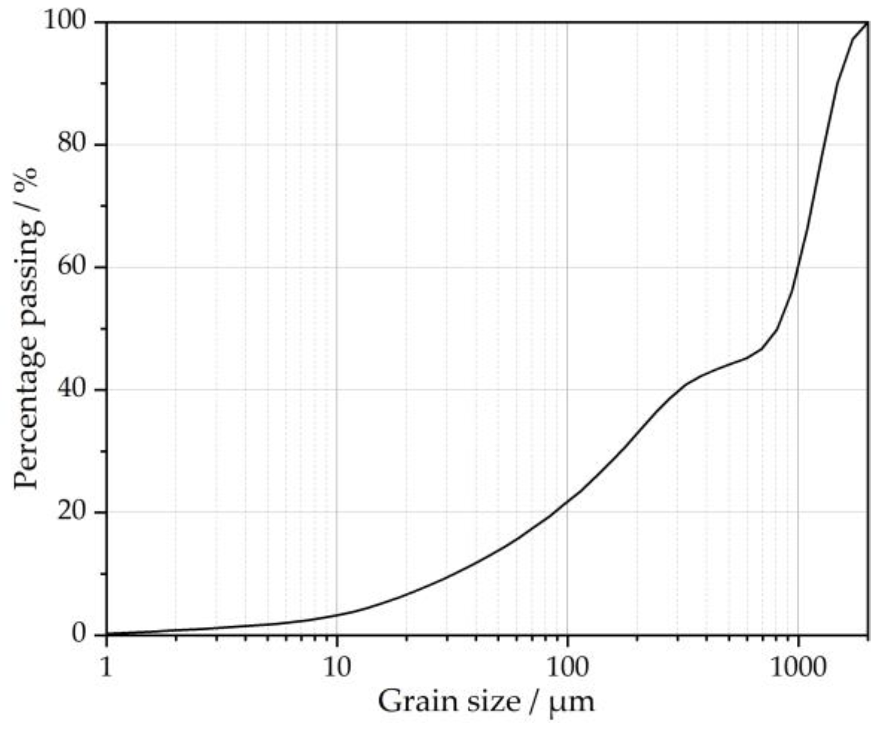
2.1. Materials
2.2. Test Scheme
2.3. Performance Requirements for Synchronized Grouting Materials
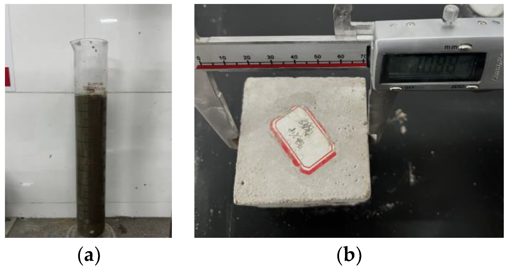
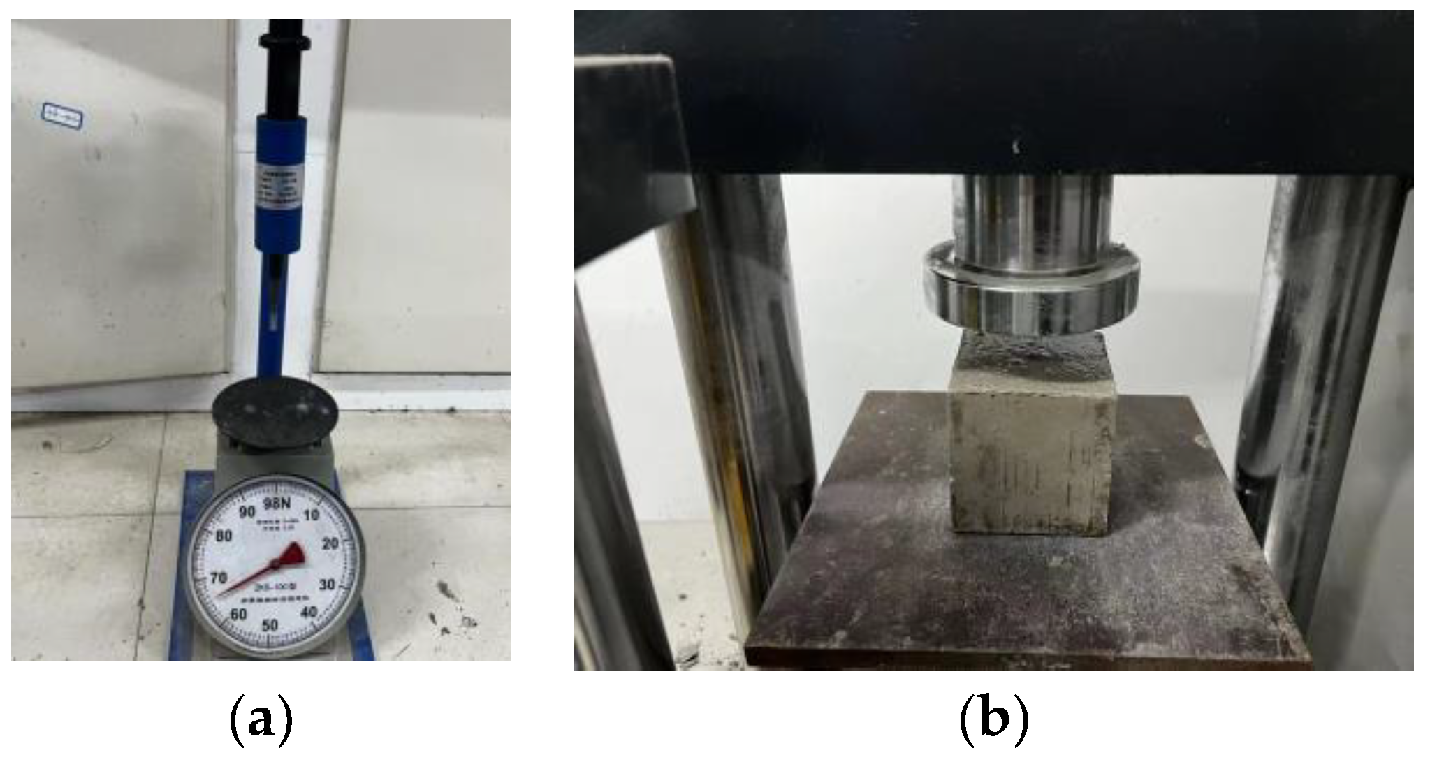
2.4. Test Method
3. Analysis of Test Results
3.1. The Influence Factors of Shield Mud Content on Slurry Performance
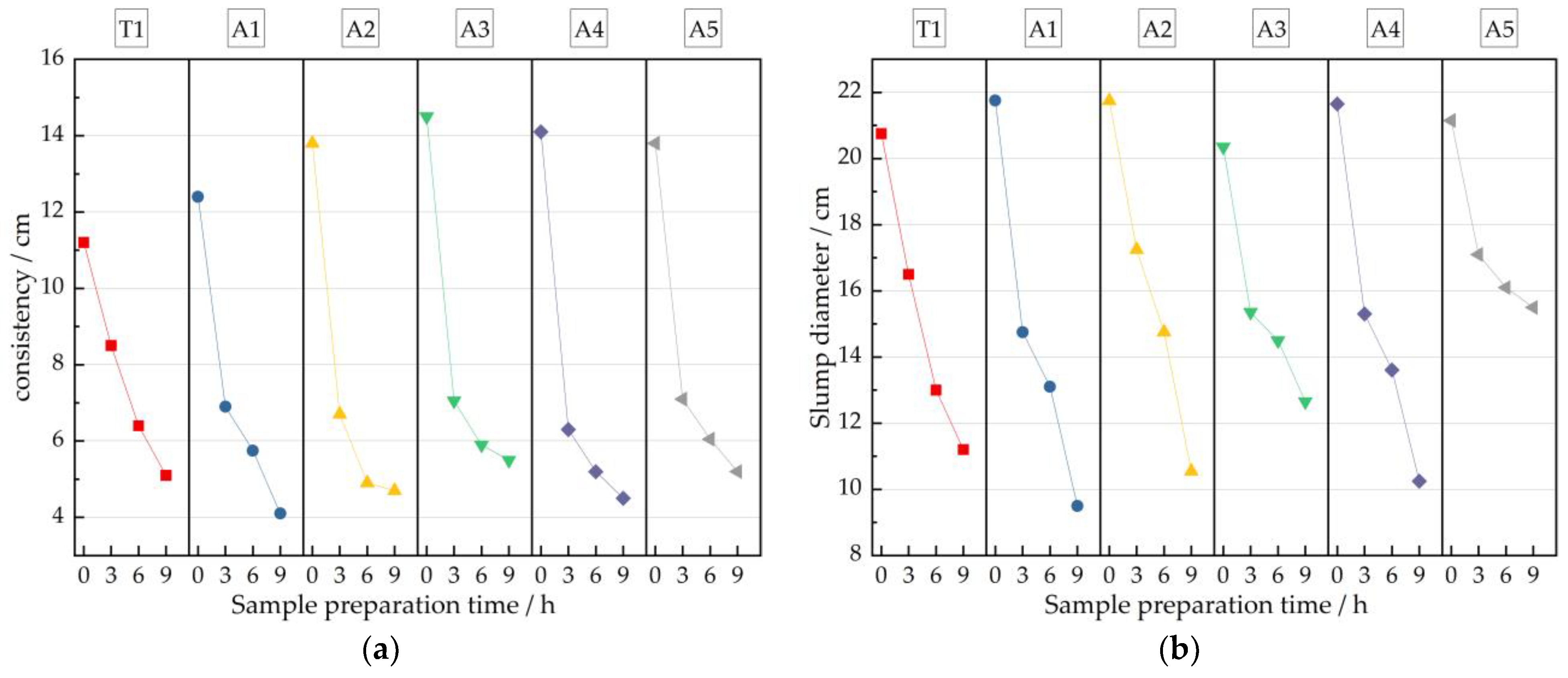
3.1.1. Effect of Shield Mud Content on Slurry Fluidity
3.1.2. Effect of Shield Mud Content on Slurry Stability
3.1.3. Effect of Shield Mud Content on Slurry Strength
3.2. Improvement Scheme of Initial Value of Slurry Consistency
3.2.1. Liquidity Improvement Effect
3.2.2. Strength Improvement Effect
3.3. Improvement Scheme of Slurry Fluidity Gradual Loss
3.3.1. Effect of Water-Reducing Agent on Slurry Fluidity
3.3.2. Effect of Water Reducer on Slurry Stability
3.3.3. Effect of Water Reducer on Slurry Strength
3.4. Study on Water Dispersion Resistance of Slurry
3.4.1. The Influence of HEMC on pH Value and Turbidity Value of Slurry
3.4.2. The Influence of HEMC Content on Slurry Fluidity
3.4.3. Effect of HEMC on the Water-to-Ground Strength Ratio of Slurries
4. Microscopic Test Results and Analysis
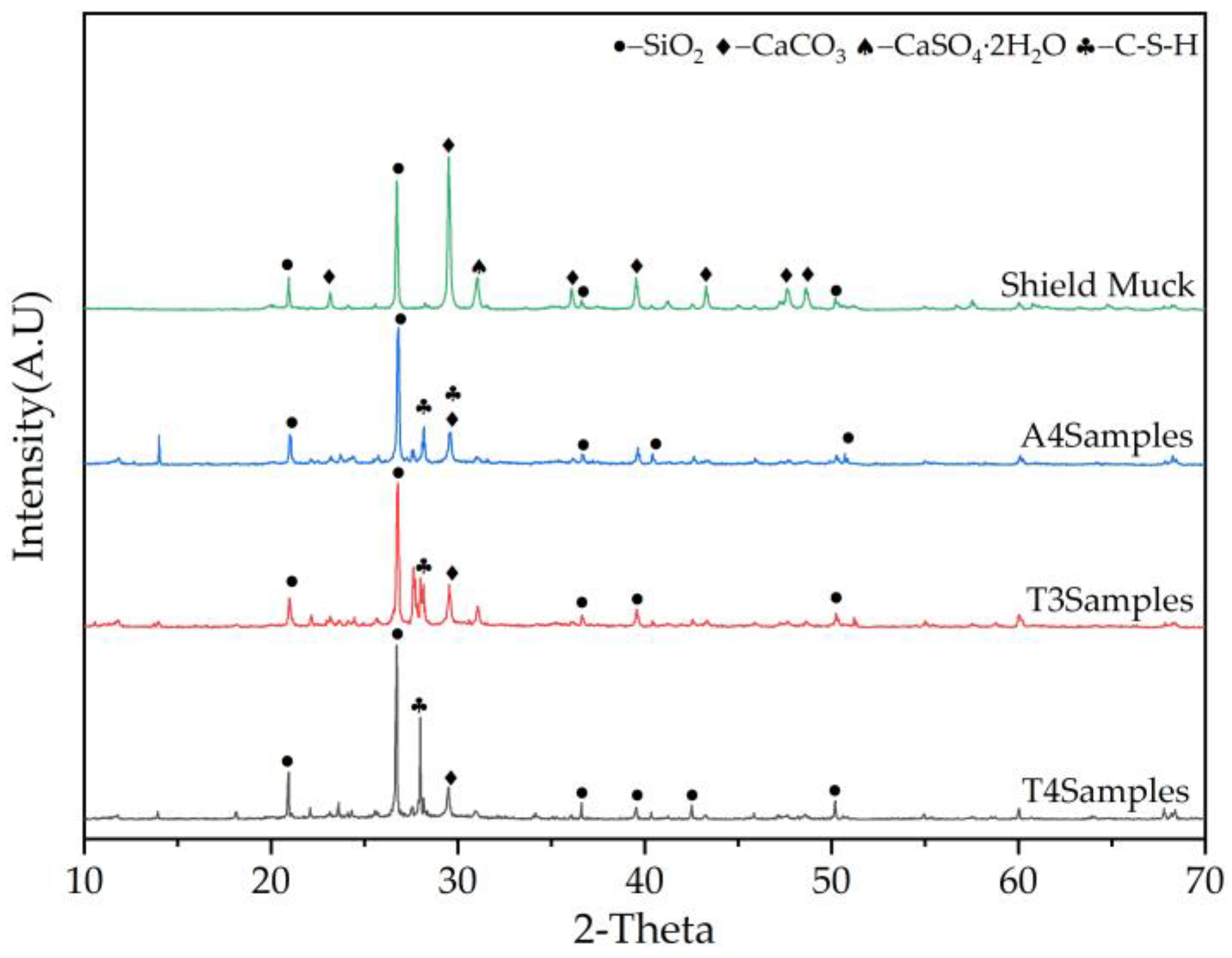
4.1. X-ray Diffraction
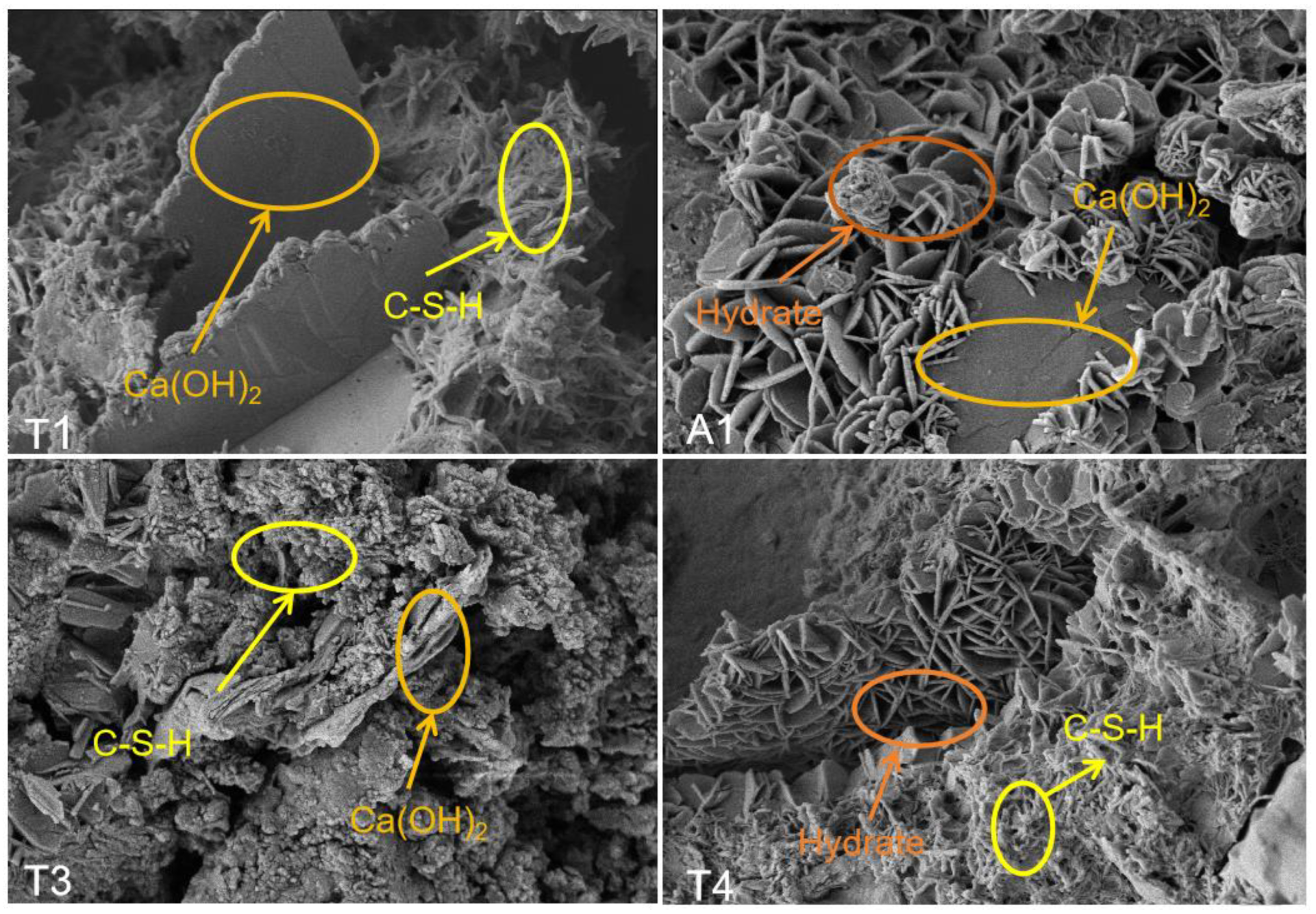
4.2. Scanning Electron Microscopy
5. Conclusions
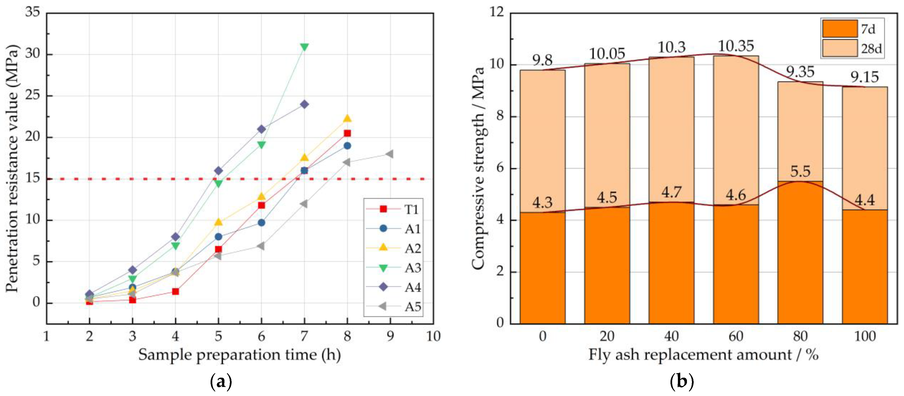
- (1)
- Tests showed that, when using clay strata shield mud to replace the fly ash in synchronous grouting material, with replacement percentages of 20%~100%, the slurry achieved good compressive strength and stability, but at the same time led to slurry consistency and slump diameter of the initial value, and the time loss was too large. At a shield mud replacement of 80%, the slurry had a stronger compressive strength and a shorter coagulation time, so the use of shield mud can not only reduce project expenditure, but also greatly shorten the project duration.
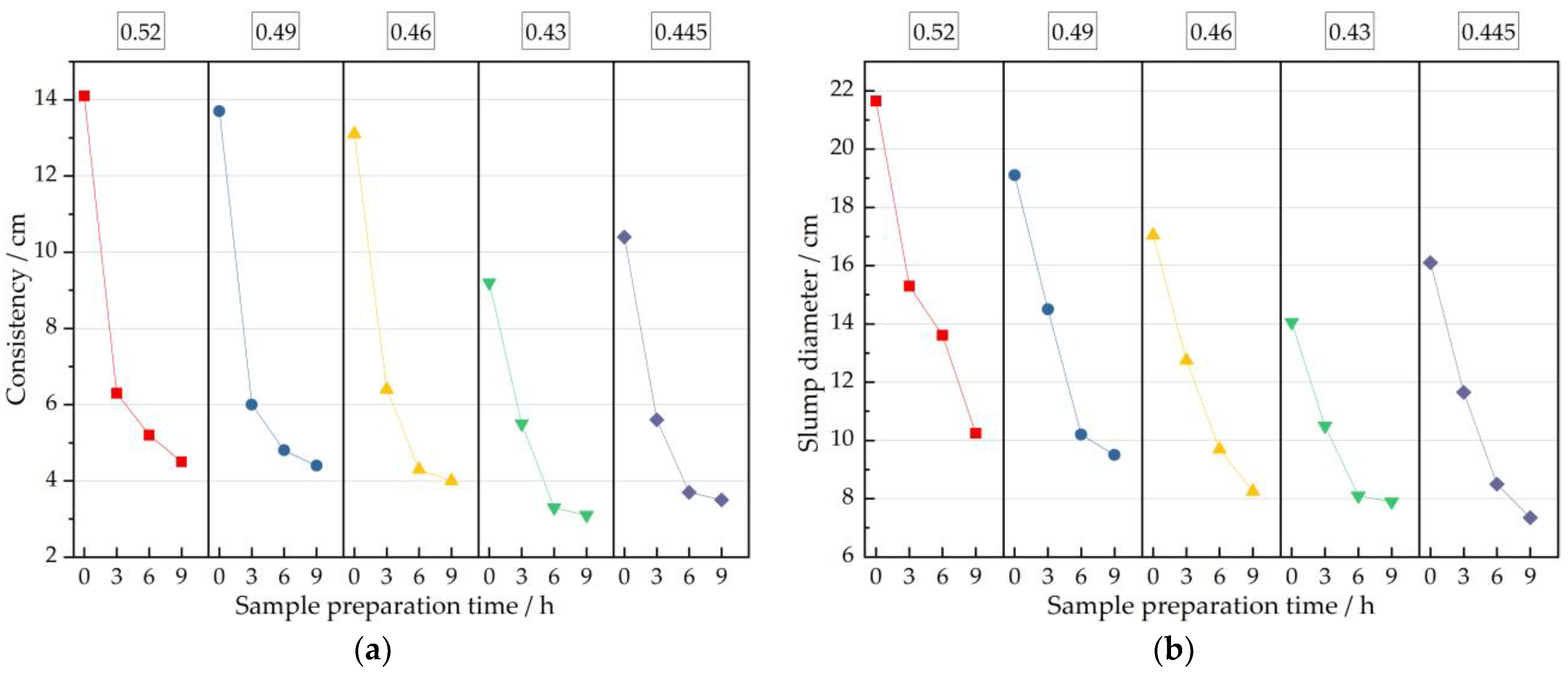
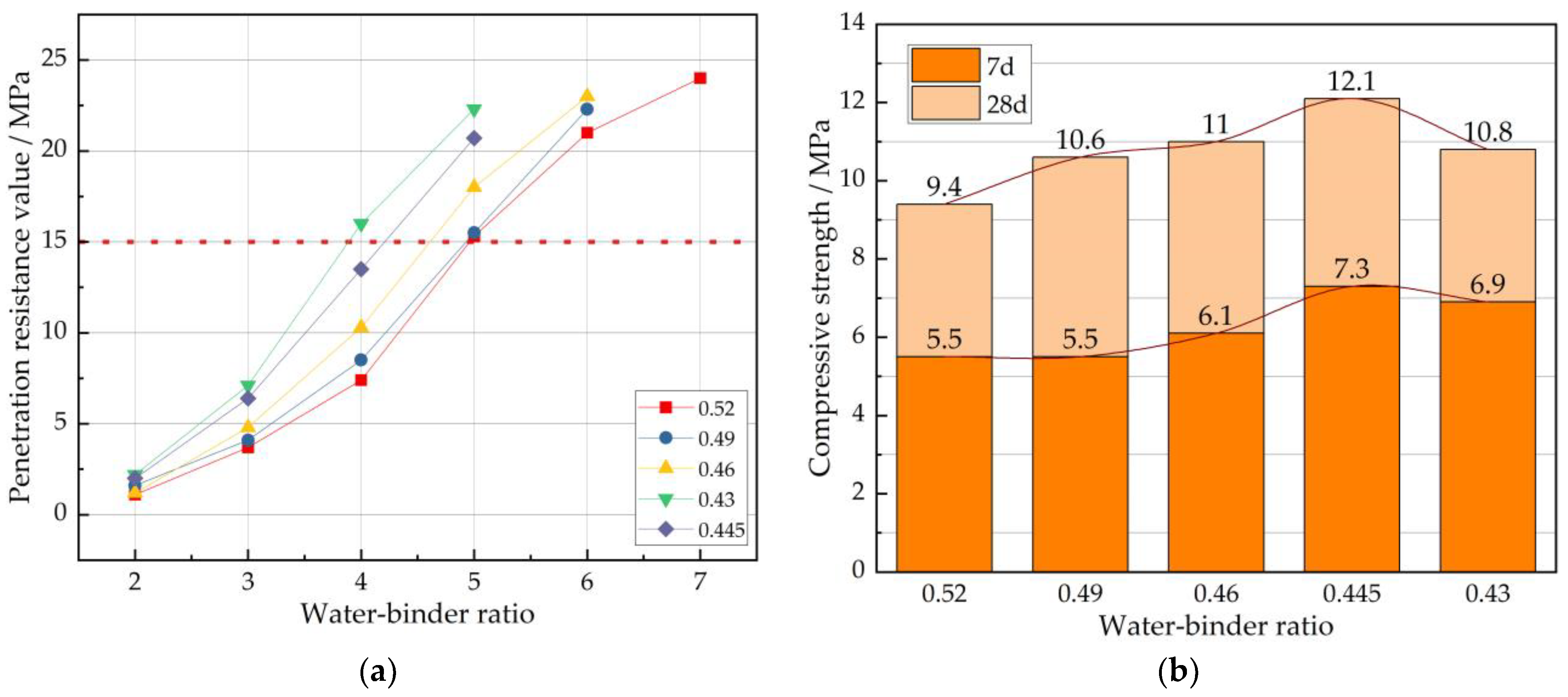
- (2)
- An experiment was conducted to investigate the effects of different water–binder ratios on the consistency, slump, and compressive strength of shield mud simultaneous grouting slurries. The results indicate that adjusting the water–binder ratio significantly improved the initial consistency of the slurry. When the water–binder ratio was 0.445, the initial consistency and slump of the slurry met the specification requirements. Furthermore, it exhibited optimal compressive strength.
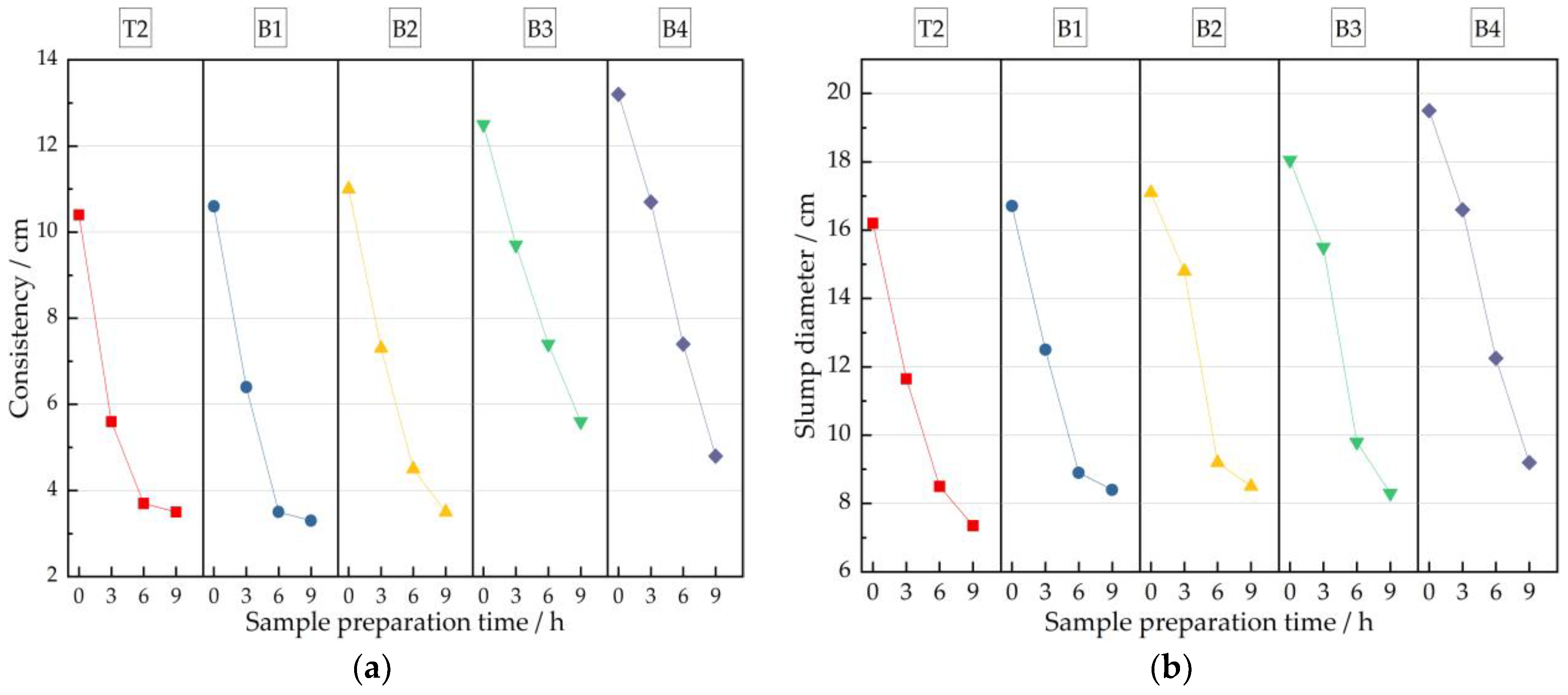
- (3)
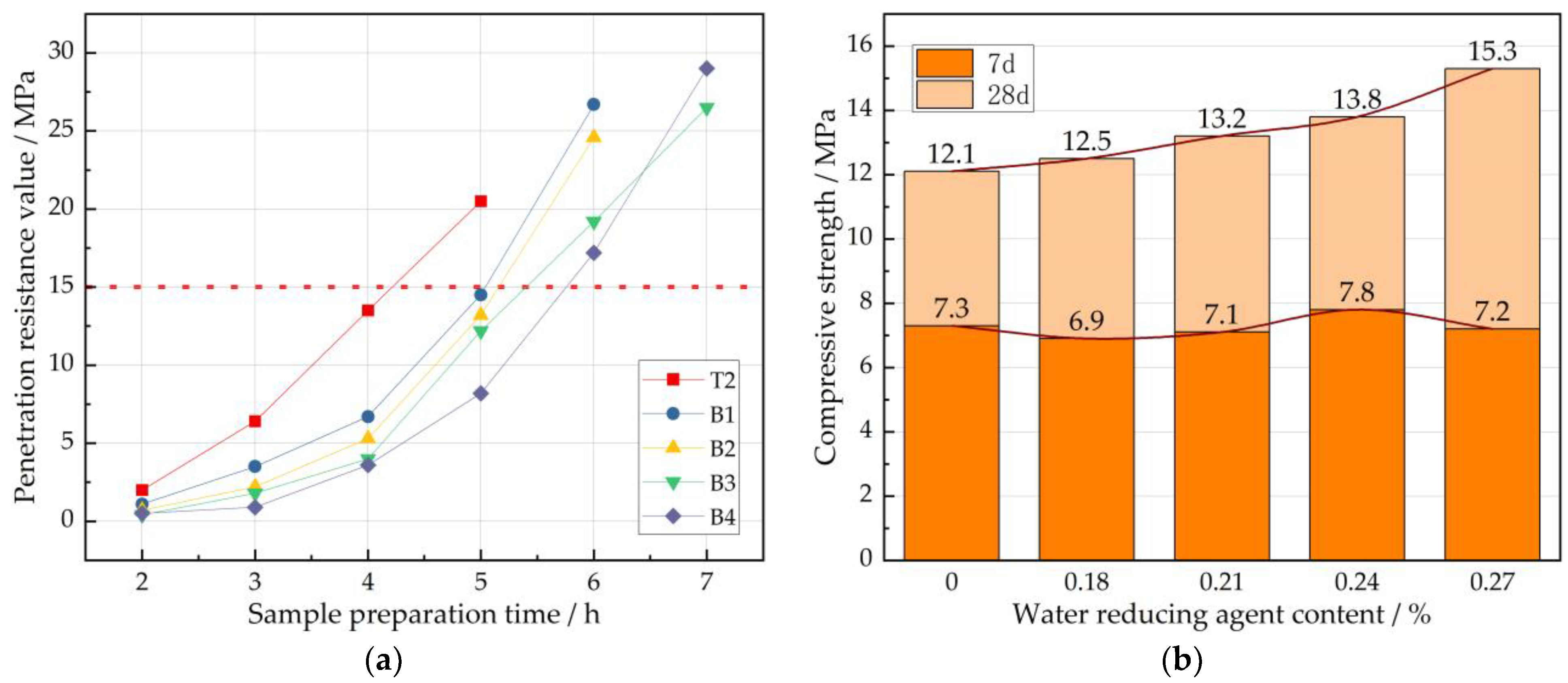
- By increasing the dosage of the polycarboxylate superplasticizer agent, the fluidity and stability of the synchronized grouting slurry could be effectively improved, and its strength showed a steady growth trend. When the dosage of the polycarboxylate superplasticizer agent was 0.24%, the slurry showed optimal performance, especially regarding the flow time loss, which significantly improved. However, if the dosage of the polycarboxylate superplasticizer agent is too high, it will lead to excessive fluidity performance of the slurry, and, at the same time, there will be no phenomenon of segregation of the slurry.
- (4)
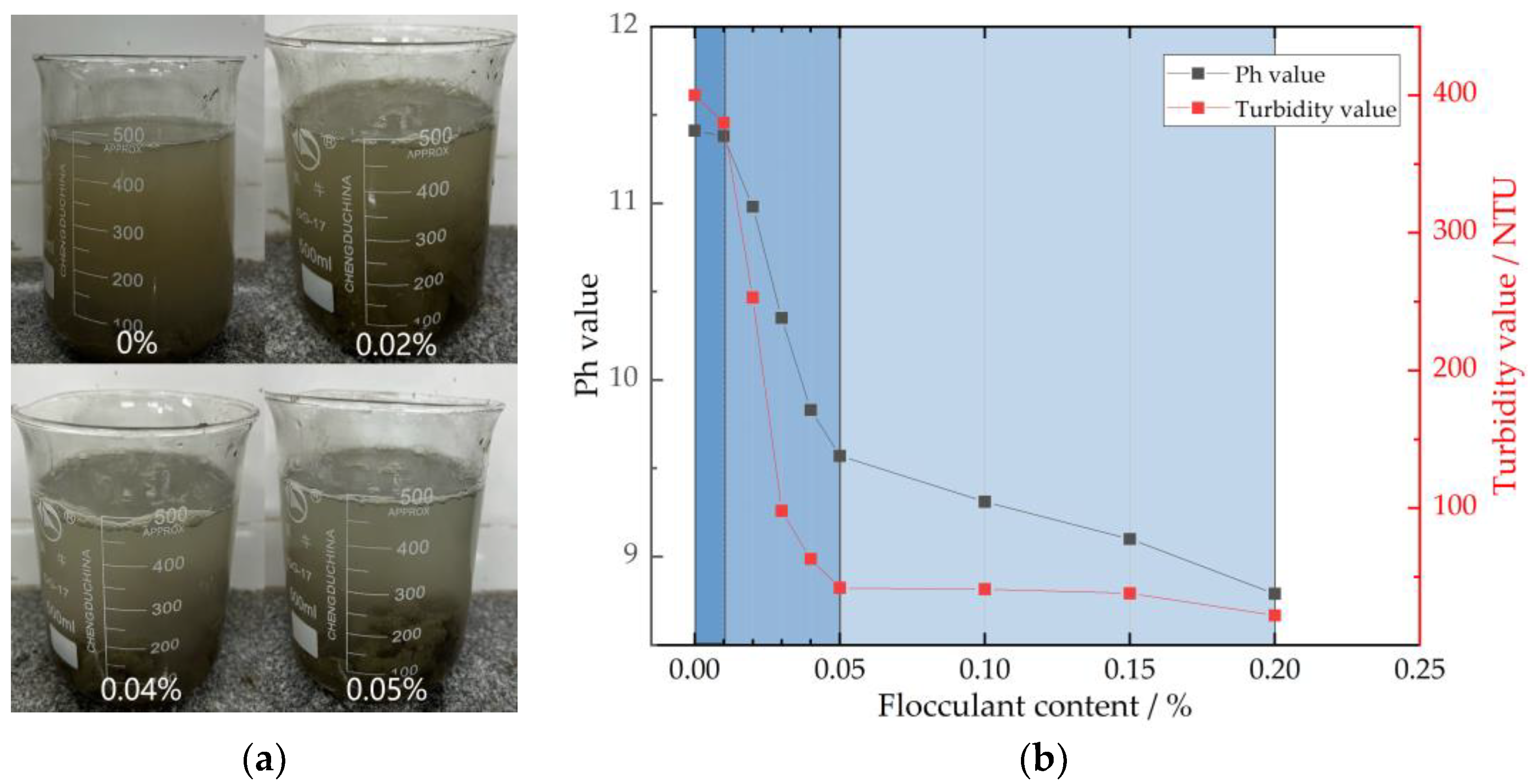
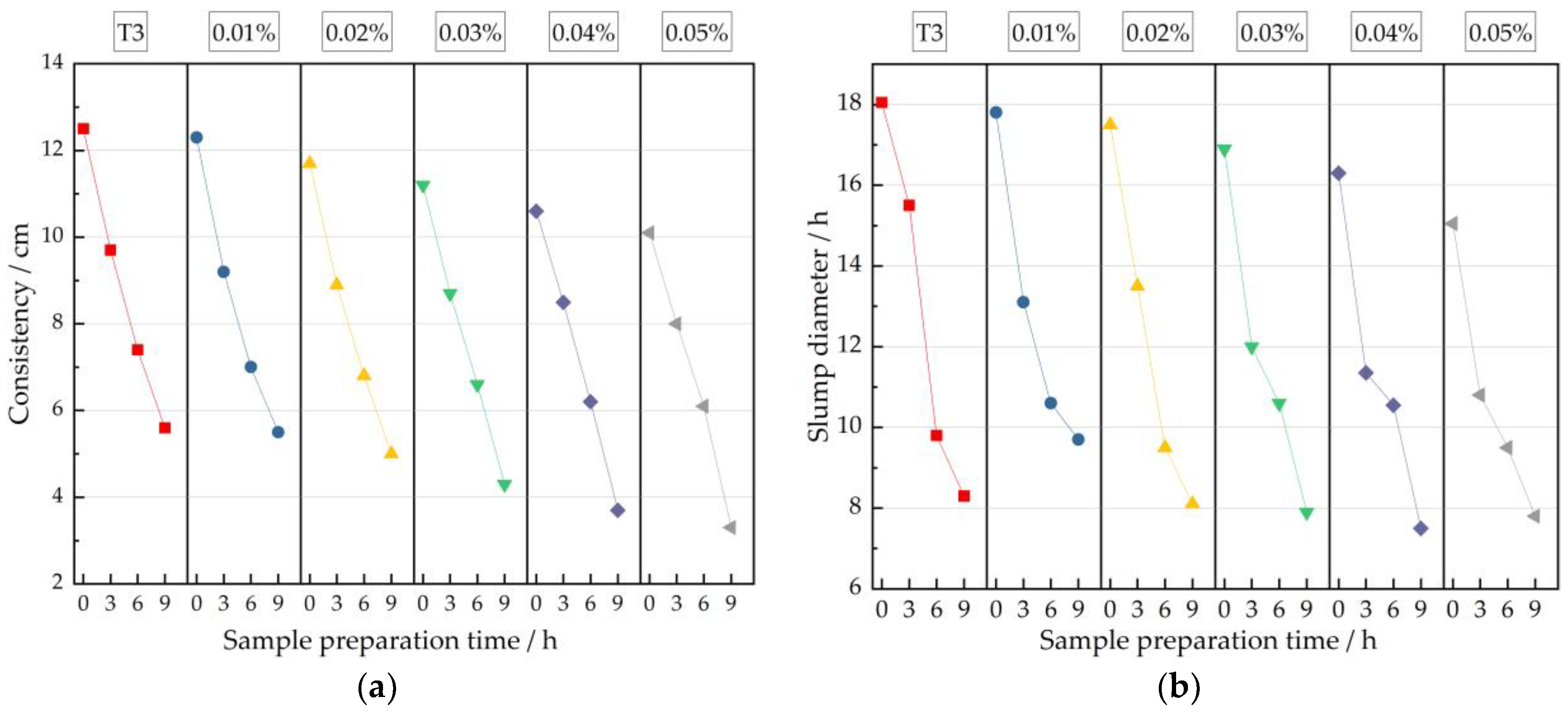
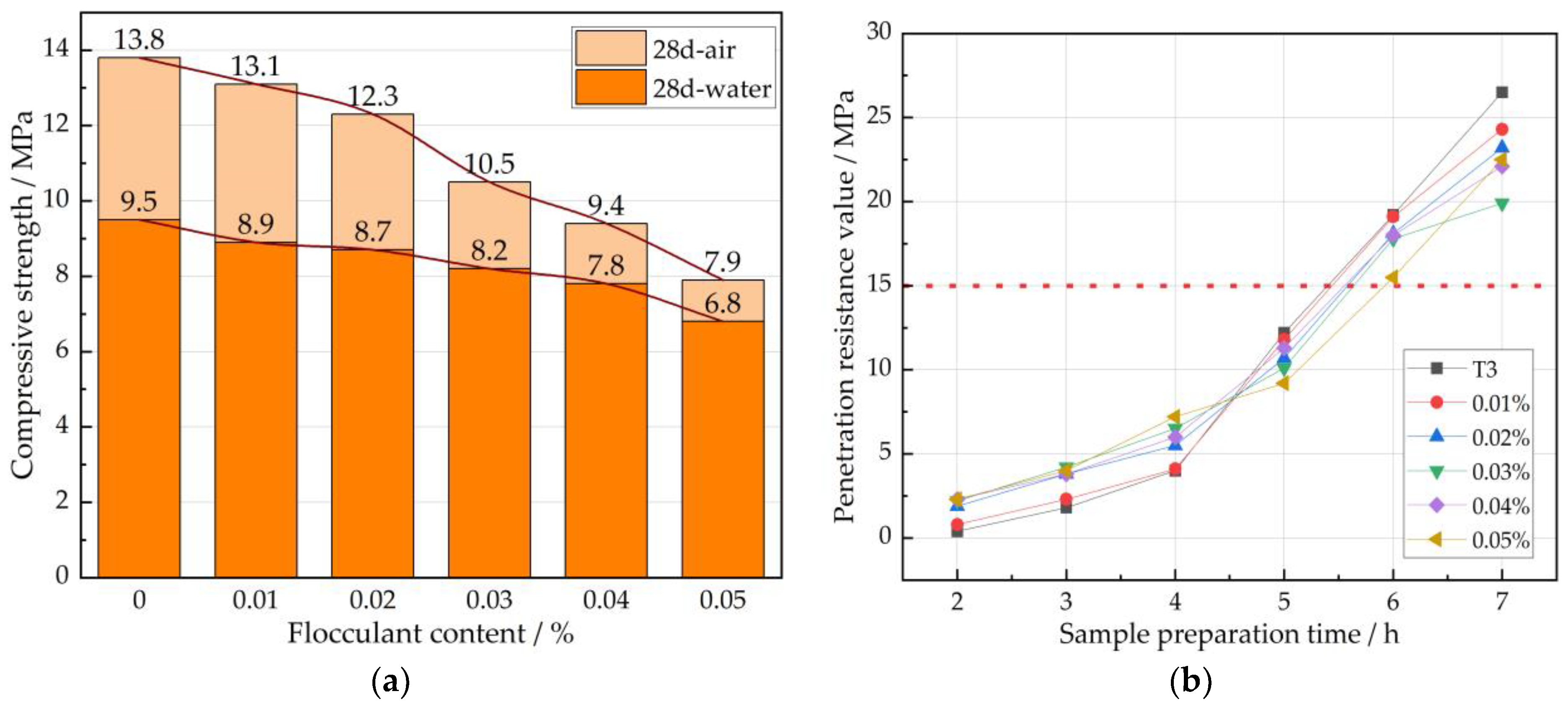
- In this study, it was found that, as the content of hydroxyethyl methyl cellulose (HEMC) in the slurry increased, the turbidity and pH of the slurry decreased and the consistency slightly reduced, while the setting time of the mortar was significantly delayed. The water dispersion resistance of the mortar was improved with 0.04% HEMC. At the same time, when the HEMC content is too high, it will seriously affect the compressive strength and fluidity of the slurry, so in the tunnel construction process, the actual water content of the geological survey environment should be used to determine the dosage of HEMC, as an excessive HEMC dosage will have a negative impact on the slurry.
- (5)
- After replacing fly ash with shield tunneling mud, XRD analysis showed a decrease in CaCO3 diffraction peaks in the shield tunneling mud, while the C-S-H diffraction peaks in the grout solution simultaneously increased, enhancing the strength formation capability. SEM analysis revealed that, in the replaced samples (A4, T3, and T4), there was a reduction in fly ash particles and the appearance of numerous interlaced hydration products, ensuring strength enhancement in the grout’s later stages. Meanwhile, the air-entraining effect of HEMC caused the loosening of the internal structure in sample T4. An analysis of the 1 μm level showed that the addition of a polyhydroxy acid water reducer delayed the hydration time and promoted the formation of C-S-H cementitious material.
Author Contributions
Funding
Data Availability Statement
Acknowledgments
Conflicts of Interest
References
- Hou, X.F.; Feng, C.H.; Yan, H.M. Overview of urban rail transit operation lines in mainland China in 2023. Urban Rapid Rail Transit 2024, 37, 10–16. [Google Scholar]
- Guo, W.S.; Wang, B.Q.; Li, Y.Z. Current status and prospects of harmless treatment and resource utilization of shield tunnel muck. Tunn. Constr. 2020, 40, 1101–1112. [Google Scholar]
- Zhu, K.F.; Zhang, Y.Y.; Xue, Z.B. Environmental issues and green treatment of shield tunnel muck. Urban Archit. 2018, 29, 032. [Google Scholar]
- Pu, C.C.; Hua, K.H.; Gao, P.H. Research progress on resource utilization of shield tunnel muck. J. Mod. Tech. Ceram. 2022, 4, 004. [Google Scholar]
- Liu, H.; Xue, D.H.; Wu, L.Y. Current situation and improvement suggestions for on-site treatment of shield tunnel muck in Shenzhen. J. Shenzhen Univ. Sci. Eng. 2022, 39, 152–158. [Google Scholar]
- Chen, R.; Yang, K.; Xiao, W. Analysis of resource utilization and treatment of engineering muck. Environ. Eng. 2020, 38, 22–26. [Google Scholar]
- Jiang, X.; Zhu, H.H.; Yan, Z.G. A state-of-art review on development and progress of backfill grouting materials for shield tunneling. Dev. Built Environ. 2023, 16, 100250. [Google Scholar] [CrossRef]
- He, S.; Lai, J.; Wang, L. A literature review on properties and applications of grouts for shield tunnel. Constr. Build. Mater. 2020, 239, 117782. [Google Scholar] [CrossRef]
- Zhou, L.; Mao, W.; Shi, M.H. Optimization Design of Synchronous Grouting Slurry Mix Ratio in Shield Tunneling. J. Wuhan Univ. Eng. 2013, 35, 29–30. [Google Scholar]
- Zhang, C.; Yang, J.; Fu, J. Recycling of Discharged Soil from EPB Shield Tunnels as a Sustainable Raw Material for Synchronous Grouting. J. Clean. Prod. 2020, 268, 121947. [Google Scholar] [CrossRef]
- Zhang, J.; Jin, J.J.; Feng, T.G. Optimization of mixture ratio of muck grout by earth pressure balance shield machine. Chin. J. Geotech. Eng. 2023, 45, 748–757. [Google Scholar]
- Cong, Z.; Kui, C.; Jun, S.Y. Reuse of Discharged Soil from Slurry Shield Tunnel Construction as Synchronous Grouting Material. J. Constr. Eng. Manag. 2022, 148, 04021193. [Google Scholar]
- Wu, T.; Gao, Y.; Huang, C. In situ resource reutilization of earth pressure balance (EPB) shield muck for the generation of novel synchronous grouting materials. Constr. Build. Mater. 2024, 421, 135737. [Google Scholar] [CrossRef]
- Ye, X.Y.; Wang, S.Y.; Yang, J.S. Soil Improvement Technology of Slurry from Muddy Sandstone Strata in Earth Pressure Balance Shield Tunneling. J. Railw. Sci. Eng. 2017, 14, 1925–1933. [Google Scholar]
- Ying, C.; Zhong, S.T. Experimental Study of High Performance Synchronous Grouting Materials Prepared with Clay. Materials 2021, 14, 1362. [Google Scholar] [CrossRef] [PubMed]
- Ni, Z.; Wang, S.; Zheng, X. Application of geopolymer in synchronous grouting for reusing of the shield muck in silty clay layer. Constr. Build. Mater. 2024, 419, 135345. [Google Scholar] [CrossRef]
- Liu, Z.X. Preparation of Unfired Bricks from Sandstone Strata Shield Tunneling Slurry and Analysis of Its Slope Protection Effect. North China Univ. Technol. 2023, 000713. [Google Scholar]
- Xi, Z.Q.; Hou, Y.K.; Li, S.S. Experimental study on the properties of non-fired bricks made from geopolymer-based fine-grained shield tunneling muck. J. Hunan Inst. Eng. 2022, 32, 83–88. [Google Scholar]
- Xu, J. Study on the reuse of shield tunneling muck incohesive soil layers for synchronous grouting. Hunan Univ. 2020, 000175. [Google Scholar]
- Lin, W.S.; Wang, H.X.; Peng, B.H. Study on the influence of shield tunneling sands from different strata on the performance of synchronous grouting materials. Tunn. Constr. 2013, 33, 715–719. [Google Scholar]
- Wang, Y.S.; Zhao, X.P.; Yuan, R. Performance and microscopic morphology analysis of shield tunnel synchronous grouting slurry prepared with weathered rock slag. J. Ho Hai Univ. 2023, 51, 65–71. [Google Scholar]
- Liu, H.G.; Ding, J.W.; Ji, F. Applicability of reusing abandoned sandy soil from shield tunnel construction at the bottom of the Yangtze River in synchronous grouting. J. Civ. Environ. Eng. 2023, 45, 134–142. [Google Scholar]
- Dai, Y.; Yang, J.S.; Zhang, C. Study on the reuse of abandoned slurry from mud-water shield tunneling in synchronous grouting materials. J. Huazhong Univ. Sci. Technol. 2019, 47, 40–45. [Google Scholar]
- Ruan, L. Study on anti-water dispersion mechanism of synchronous grouting in highly permeable and water-rich strata by shield tunneling. Southwest Jiao Tong Univ. 2019, 000109. [Google Scholar]
- Zhu, X.F.; Song, P.Y.; Du, F. Study on durability and anti-water dispersion performance of high-performance synchronous grouting materials. Concrete 2021, 12, 157–160. [Google Scholar]
- T/CECS 563-2018; Building Materials World. China Association for Engineering Construction Standardization: Beijing, China, 2022; Volume 2, pp. 7–23.
- JGJ/T 70-2009; Standard for Basic Performance Test Methods of Building Mortar. Ministry of Housing and Urban-Rural Development: Beijing, China, 2009; Volume 2, pp. 7–13.
- JC/T 2153-2012; Test Method for Bleeding of Cement. National Standardization Technical Committee Cement: Beijing, China, 2012; Volume 1, pp. 2–9.
- Ma, K.L.; Feng, J.; Long, G.C. Rheological characteristics and mechanism of cement-fly ash slurry. J. Railw. Sci. Eng. 2017, 14, 465–472. [Google Scholar]
- Li, S.; Yu, Q.J.; Wei, J.X. Influence of molecular structure of polycarboxylate superplasticizer on cement hydration process. J. Chin. Ceram. Soc. 2012, 40, 613–619. [Google Scholar]
- Su, Z.Z.; Lin, M.S.; Zhang, Z.W. Discussion on retarding mechanism of polycarboxylate superplasticizers. J. Sanming Univ. 2005, 4, 401–405. [Google Scholar]
- Ma, B.G.; Tan, H.B.; Dong, R.Z. Study on retarding mechanism of polycarboxylate superplasticizers. Yangtze River Sci. Res. Inst. 2008, 25, 93–95. [Google Scholar]
- Fang, M.M.; Xi, X.L.; Lin, D. Research status and application prospects of polycarboxylate superplasticizers. Mater. Rev. 2008, 3, 76–79. [Google Scholar]
- Saric-Coric, M.; Khayat, K.H.; Tagnit-Hamou, A. Performance characteristics of cement grouts made with various combinations of high-range water reducer and cellulose-based viscosity modifier. Cem. Concr. Res. 2003, 33, 1999–2008. [Google Scholar] [CrossRef]
- Wang, P.M.; Xu, Q.; Li, W.W. The influence of hydroxyethyl methyl cellulose on the properties of cement mortar. J. Build. Mater. 2000, 04, 305–309. [Google Scholar]
- Kovalenko, Y.; Tokarchuk, V.; Poliuha, V. The impact of methyl hydroxyethyl cellulose on cement matrix properties. East.-Eur. J. Enterp. Technol. 2020, 3, 28–33. [Google Scholar]
- Ou, Z.H.; Ma, B.G.; Jian, S.W. Influence of cellulose ether molecular parameters on the mechanical properties of cement slurry. Bull. Chin. Ceram. Soc. 2016, 35, 2371–2377. [Google Scholar]
- Zhang, G.F.; Wang, P.M. The effect of hydroxyethyl methyl cellulose on cement hydration. J. Tongji Univ. 2009, 37, 369–373. [Google Scholar]


| Sample Name | CaO | SiO2 | Al2O3 | MgO | Fe2O3 |
|---|---|---|---|---|---|
| Fly Ash | 9.25 | 49.55 | 29.37 | 3.23 | 5.33 |
| Cement | 51.42 | 24.99 | 8.26 | 3.71 | 4.03 |
| Bentonite | 66.7 | — | 28.3 | — | — |
| Sample Name | Displacement Volume (%) | Fly Ash (g) | Shield Mud (g) | Cement (g) | Water (g) | Bentonite (g) | Sand (g) | Water–Binder Ratio |
|---|---|---|---|---|---|---|---|---|
| T1 * | 0 | 230 | 0 | 185 | 254 | 75 | 510 | 0.52 |
| A1 | 20% | 184 | 46 | |||||
| A2 | 40% | 138 | 92 | |||||
| A3 | 60% | 92 | 138 | |||||
| A4 | 80% | 46 | 184 | |||||
| A5 | 100% | 0 | 230 |
| Performance Name | Consistency (cm) | The Loss in Consistency (cm/h) | Slump Diameter (cm) | Slump Loss (cm/h) | Bleeding Rate (%) | Volume Shrinkage (%) | Setting Time (h) | 7-Day Compressive Strength (MPa) | 28-Day Compressive Strength (MPa) |
|---|---|---|---|---|---|---|---|---|---|
| Performance requirements | 10~13 | <1 | >16 | <2 | ≤3.5 | ≤5 | 4 < h < 6 | ≥3.5 | ≥7 |
| Water–Binder Ratio | Water (g) | Cement (g) | Fly Ash (g) | Bentonite (g) | Shield Mud (g) |
|---|---|---|---|---|---|
| 0.52 | 254 | 185 | 46 | 75 | |
| 0.49 | 240 | 184 | |||
| 0.46 | 225 | ||||
| 0.43 | 211 |
| Sample Name | Water-Reducing Agent (%) | Water–Binder Ratio | Sand (g) | Water (g) | Binding Material 2 (g) |
|---|---|---|---|---|---|
| B1 1 | 0.18 | 0.445 | 510 | 218 | 490 |
| B2 | 0.21 | ||||
| B3 | 0.24 | ||||
| B4 | 0.27 |
| Sample Name | Binding Material (g) | Sand (g) | Water (g) | Water–Binder Ratio | HEMC (%) | Polycarboxylate Superplasticizer (%) |
|---|---|---|---|---|---|---|
| T4 | 490 | 510 | 218 | 0.445 | 0.04 | 0.24 |
Disclaimer/Publisher’s Note: The statements, opinions and data contained in all publications are solely those of the individual author(s) and contributor(s) and not of MDPI and/or the editor(s). MDPI and/or the editor(s) disclaim responsibility for any injury to people or property resulting from any ideas, methods, instructions or products referred to in the content. |
© 2024 by the authors. Licensee MDPI, Basel, Switzerland. This article is an open access article distributed under the terms and conditions of the Creative Commons Attribution (CC BY) license (https://creativecommons.org/licenses/by/4.0/).
Share and Cite
Fan, Y.; Gao, Y.; Tao, W.; Huang, S. Study on the Reuse of Shield Mud from Clay Stratum in Synchronous Grouting Slurry. Buildings 2024, 14, 2537. https://doi.org/10.3390/buildings14082537
Fan Y, Gao Y, Tao W, Huang S. Study on the Reuse of Shield Mud from Clay Stratum in Synchronous Grouting Slurry. Buildings. 2024; 14(8):2537. https://doi.org/10.3390/buildings14082537
Chicago/Turabian StyleFan, Ying, Yang Gao, Weilong Tao, and Sihong Huang. 2024. "Study on the Reuse of Shield Mud from Clay Stratum in Synchronous Grouting Slurry" Buildings 14, no. 8: 2537. https://doi.org/10.3390/buildings14082537
APA StyleFan, Y., Gao, Y., Tao, W., & Huang, S. (2024). Study on the Reuse of Shield Mud from Clay Stratum in Synchronous Grouting Slurry. Buildings, 14(8), 2537. https://doi.org/10.3390/buildings14082537