Abstract
Expansion joints render bridge structures highly vulnerable to damage during strong ground motions. Failures of expansion joints triggered by earthquakes not only jeopardize the post-earthquake serviceability of the bridge but also have a significant impact on the bridge’s overall seismic performance. Despite extensive investigations and efforts to integrate these measures into design specifications aimed at mitigating the consequences of relative movements between adjacent bridge spans, major earthquakes have still revealed instances of damage related to expansion joints. On 6 February 2023, strong earthquake sequences occurred in Kahramanmaraş, Turkey, with magnitudes of M7.7 and M7.6. The fault lines and epicenters of these shallow earthquakes were near the city and town centers and caused severe structural damage to buildings and infrastructures. There are approximately 1000 railway and highway bridges in the earthquake-affected region. Although both highway and railway bridges have generally performed well, some bridges experienced structural damage during the Kahramanmaraş earthquakes. A large number of damage on the bridges is due to pounding and opening relative movements in expansion joints. This paper presents a comprehensive seismic evaluation of expansion joint failure mechanisms on bridges without viscous dampers during the 2023 Kahramanmaraş earthquake sequences and an in-depth investigation into the seismic performance of bridge expansion joints equipped with viscous dampers and shock transmission unit devices are implemented utilizing the strong ground motion data collected throughout the earthquake sequences. It can be stated that the near-fault induced significant directivity and fling effects, resulting in notable velocity pulses and permanent tectonic deformations, and that these effects contributed to the failures of expansion joints, viscous damper devices, pot bearings, and shear keys.
1. Introduction
Bridges with multiple spans are equipped with expansion joints to mitigate the effects of various factors, including creep, shrinkage, thermal expansion and contraction, shortening due to applied loads, live loads (both vertical and horizontal forces resulting from braking), wind, earthquakes, and foundation settlements [1,2]. However, the presence of these expansion joints makes bridge structures highly susceptible to damage during strong ground motions. Collisions between adjacent bridge components (such as deck-to-deck and deck-to-abutment connections) can occur when the relative closing displacement exceeds the size of the expansion gap. Moreover, strong ground motions can lead a potential increase in relative opening movement between adjacent components of the bridge. The failures of expansion joints caused by earthquakes not only threaten the post-earthquake serviceability of the bridge but also impact the bridge’s overall seismic performance [3]. It is worth noting that the most significant factors influencing the magnitude of expansion joint movements under earthquake conditions are the variations in the vibrational properties of adjacent bridge spans, fluctuations in ground motions at bridge supports, and the variability in soil–structure interaction [4].
To mitigate the issues of pounding and opening in bridge spans, various preventive measures have been suggested. These include the use of steel cable/bar restrainers, shape memory alloy restrainers, fiber-reinforced polymer restrainers, damping devices (such as metallic dampers, viscoelastic dampers, and fluid viscous dampers), modular expansion joints, shock-absorbing devices, hybrid solutions, and modular expansion joints. Despite numerous investigations and efforts to incorporate these measures into design specifications aimed at avoiding or reducing the consequences of relative movements between adjacent bridge spans, incidents of damage related to these movements have been observed in previous major earthquakes. Notable examples include the 1971 San Fernando earthquake (USA), 1989 Loma Prieta earthquake (USA), 1995 Kobe earthquake (Japan), 1994 Northridge earthquake (USA), 1999 Chi-Chi earthquake (Taiwan), 1999 Kocaeli earthquake (Turkey), 1999 Düzce earthquake (Turkey), 2006 Yogyakarta earthquake (Indonesia), 2008 Wenchuan earthquake (China), 2010 Maule earthquake (Chile), 2011 Christchurch earthquake (New Zealand), and 2023 Kahramanmaraş earthquakes (Turkey).
Owing to the vital role of bridges in transportation networks, there has been a substantial increase in research on expansion joints in bridge structures. These studies aim to comprehensively understand this phenomenon and identify the most effective mitigation measures during seismic events. Feng et al. [5] conducted a study on implementing viscoelastic dampers at expansion joints in highway bridges to prevent superstructure decks from dislodging from their seats or colliding with each other during severe earthquakes. Zhu et al. [6] introduced a 3D modeling approach for the nonlinear analysis of elevated bridges exposed to strong ground motion, accounting for arbitrary pounding between bridge girders and experiments were performed to validate the proposed pounding model. Ruangrassamee and Kawashima [7] conducted an investigation into the effectiveness of variable dampers in enhancing seismic response, considering the impact of pounding. Their findings revealed that the friction-type damping force scheme resulted in the most significant reductions in deck displacement, relative displacement between two decks, and the flexural hysteretic curvature at the plastic hinge of a pier.
Li et al. [8] evaluated girder bridge damages, which include span collapses due to unseating at expansion joints, shear key failure, and expansion joint failure due to the slide-induced large relative displacement between the bottom of the girder and the top of the laminated-rubber bearing, on National Highway 213 and the Dujiangyan-Wenchuan expressway during 2008 Wenchuan earthquake. Chouw and Hao [4,9,10] conducted comprehensive investigations into the effects of soil–structure interaction and the spatial variation of ground motions on the response of bridge expansion joints. Chouw and Hao [11] addressed the damage to buildings and bridges resulting from relative movements between adjacent structures observed from inspections and in-the-field investigations in Christchurch and surroundings after the devastating earthquake of 22 February 2011. Guo et al. [12] conducted a comprehensive study involving the long-term monitoring and analysis of expansion joint displacements, with a specific focus on the impact of viscous dampers installed to mitigate seismic responses in bridges. According to the monitoring data, the presence of viscous dampers can reduce displacements caused by vehicles and wind but it has no significant influence on temperature-induced movements.
Gao et al. [3] developed a new device named cable-sliding modular expansion joints to investigate the effect of controlling the relative displacement and avoid collision. Sun and Zhang [13] examined the failure mechanism of expansion joints in a suspension bridge through both field tests and a numerical study. Mahjoubi and Maleki [14] proposed a straightforward displacement-based procedure for designing dual-pipe dampers and infilled-pipe damper elements to prevent deck-abutment impacts in bridges with expansion joints. Shrestha et al. [2] provided an extensive review of the contemporary literature concerning experimental and numerical studies on devices applied externally to bridge superstructures to mitigate pounding and unseating damage in highway bridges. They discussed the advantages and limitations of these devices in practical applications. Li and Shi [15] investigated the seismic isolation design of near-fault bridges under the seismic excitations of near-fault ground motions in high-intensity earthquake zones and proposed a combined control system using lead rubber bearings and cable displacement restrainers.
Miari et al. [1] conducted a review of prior research studies focusing on earthquake-induced structural pounding in bridge structures, the influencing factors, and recommended mitigation measures. Khedmatgozar Dolati et al. [16] numerically investigated the effectiveness of viscous damper and laminated rubber bearing pads for controlling the large displacement between superstructure and substructure under several earthquakes, considering the finite element model validated with the experimental results. To investigate the effect of seismic isolation bearings on the potential pounding between adjacent girders considering the wave passage effect, a finite element model of a bridge system consisting of two box-girder bridges and one long-span hybrid truss-box girder bridge was developed by Guo et al. [17]. Meng et al. [18] reviewed previous research on seismically induced pounding in both motorway and high-speed rail bridges. Eraky et al. [19] conducted a numerical study to assess the benefits and effectiveness of shape memory alloy seismic restrainers in preventing joint openings in various bridge scenarios under different seismic conditions.
The literature review provided above underscores a substantial body of research dedicated to elucidating the responses of bridge expansion joints subjected to seismic forces. In the context of the 2023 Kahramanmaraş earthquakes, registering magnitudes of M7.7 and M7.6, bridges experienced structural damage. The main objectives of this study are (a) to provide a comprehensive assessment of expansion joint failures on bridges without viscous dampers during strong near-fault earthquakes and (b) to conduct an in-depth investigation of the seismic performance of bridge expansion joints equipped with viscous dampers using strong ground motion monitoring data collected during the earthquake sequences. These objectives will significantly enhance the understanding of the response of bridge expansion joints to seismic events, particularly strong near-fault earthquakes. The results will inform the seismic evaluation and design of both existing and new bridges, with and without viscous dampers, thereby advancing engineering practices to improve infrastructure resilience.
2. An Overview of the 2023 Kahramanmaraş Earthquakes
Tectonic activity in Turkey is primarily driven by two major active fault systems: the East Anatolian Fault (EAF) and the North Anatolian Fault (NAF). The EAF spans approximately 450 km and exhibits a northeast-trending, left-lateral strike-slip fault configuration, extending from Karlıova to Hatay [20]. On 6 February 2023, at 04:17 a.m. local time (01:17 GMT), an earthquake with a moment magnitude of M7.7 and a depth of 8.6 km struck Pazarcık-Kahramanmaraş, Turkey, along the EAF [21]. Just 10 min later, at 04:28 a.m. local time (01:28 GMT), a strong aftershock, with a depth of 6.2 km and a moment magnitude of M6.6, occurred in Nurdağı-Gaziantep, Turkey, also along the EAF. Approximately nine hours later, at 13:24 p.m. local time (10:24 GMT), Elbistan-Kahramanmaraş, Turkey, experienced another earthquake, with a magnitude of M7.6 and a depth of 7.0 km. In addition, a significant third earthquake with a magnitude of M6.4 and a depth of 21.73 km struck Yayladağ-Hatay, also on the EAF, on 20 February 2023, at 20:04 p.m. local time (17:04 GMT). Figure 1 displays major active faults and the locations of the epicenters of the mainshocks and aftershocks of the 6 February 2023 Kahramanmaraş, Turkey, earthquakes.
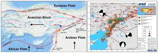
Figure 1.
The major active faults of Turkey and the epicenters of the mainshocks and aftershocks of the 6 February 2023, Kahramanmaraş earthquakes [22,23].
The shake intensity maps, PGAs, and affected cities of the 6 February 2023 Kahramanmaraş, Turkey, earthquakes are given in Figure 2. The 2023 Kahramanmaraş earthquakes affected 11 cities with residents of over 14 million and the north part of Syria. A total of 50,783 people lost their lives and 115,353 people were injured. According to the damage assessment dated 2 May 2023 from the Ministry of Environment, Urbanization, and Climate Change, the number of collapsed or urgently demolished buildings in the region is reported as 58,039, while the number of severely damaged buildings is 205,534. In addition to the buildings, the 2023 Kahramanmaraş earthquakes also caused significant damage to engineering structures such as bridges, dams, tunnels, etc.

Figure 2.
The shake intensity maps, PGAs, and affected cities during the 6 February 2023, Kahramanmaraş earthquakes [22].
3. Seismic Failure Mechanisms of Bridge Expansion Joints
There are approximately 1000 railway and highway bridges in the earthquake-affected region [24]. Overall, both railway and highway bridges have performed well. However, earthquake-induced damage has been observed in some bridges. The observed damage issues are expansion joint openings, pounding of adjacent girder and expansion joints, sliding between the girder and bearings, settlement at supports, steel plate crushing, concrete pouring in columns, interior and exterior shear key failures, cracking in abutments, longitudinal and transverse joint offsets, liquefaction in foundations, and damage to supports [21]. It can be stated that a large amount of the damage in bridges is pounding and opening relative movements in expansion joints and shear keys.
The primary cause of damage was the shorter hypocenter distance to the cities and structures, coupled with the consecutive impact of earthquake sequences. Another contributing factor was the strong effect of directivity on the city and its structures. These two primary factors were manifested in the very high horizontal and vertical ground accelerations, characterized by significant high-frequency content. The combined lateral, longitudinal, and vertical motions resulted in damage to many expansion joints. Below, the observed failure mechanisms of bridge expansion joints with and without viscous dampers during the 2023 Kahramanmaraş earthquakes are presented and discussed.
3.1. Failures at Expansion Joints without Viscous Dampers
One of the affected bridges without viscous dampers during the 2023 Kahramanmaraş earthquakes is the Adıyaman Aksu Bridge, located in the city of Adıyaman. This bridge comprises two parallel parts, denoted as A and B. It was constructed in 2012 using reinforced concrete prestressed simple beams. Both parts, A and B, are divided into three spans, with a distance of 28.50 m between supports, a total length of 87.40 m, and a width of 9.50 m. The nearest earthquake station to the bridge is the TK0213 station located in the Tut district center. During the M7.7 earthquake at the TK0213 station, the PGAH (horizontal peak ground accelerations) values were recorded as 171.70 cm/s2 in the E-W direction and 242.28 cm/s2 in the N-S direction. The PGAV (vertical peak ground acceleration) value recorded in the vertical direction was 291.29 cm/s2 [25]. The TK0213 station is situated at a distance of 96.48 km from the epicenter of the M7.7 earthquake and the distance from the station to the bridge is 19.01 km. It can be stated that the E-W and N-S components induced pronounced lateral and longitudinal movements in the bridge deck girders, while the vertical component resulted in vertical impact effects on the girders. Figure 3 provides a visual representation of the earthquake’s impact, highlighting damage to the exterior shear keys, the top flange of the girders, and the expansion joints.
Figure 3.
Exterior shear key, girder top flange, and expansion joint damage on Adıyaman Aksu Bridge.
The Adıyaman Cendere Bridge, located in the city of Adıyaman, was constructed using reinforced concrete prestressed simple beams in 2001. The bridge consists of 11 spans with a distance between supports of 24.30 m, a total length of 299.95 m, and a width of 7.95 m. The nearest strong ground motion station to the bridge is the TK0201 station, located in Adıyaman city center. During the M7.7 earthquake, the PGAH values recorded were 879.95 cm/s2 in the E-W direction and 474.12 cm/s2 in the N-S direction. The PGAV value recorded in the vertical direction was 318.97 cm/s2. The shear wave velocity of the foundation soil at the TK0201 station is 391 m/s [25]. The distance from the TK0201 station to the epicenter of the M7.7 earthquake is 120.12 km and the distance from the station to the bridge is 35.27 km. Interior and exterior shear key damage, along with an expansion joint opening, was observed on the bridge due to the E-W and N-S components of the M7.7 earthquake. Figure 4 shows the interior and exterior shear key damage and the expansion joint opening that occurred in the bridge.

Figure 4.
Shear key and expansion joint damages on the Adıyaman Cendere Bridge.
The Nurdağı Şehitler Viaduct is located in the Nurdağ district. It has a total length of 310 m and consists of 8 spans. The viaduct was constructed using prestressed reinforced concrete prefabricated beams. The nearest acceleration station to the bridge is the TK2712 station, located in the Nurdağ district. The distance from the TK2712 station to the epicenter of the M7.7 earthquake is 29.79 km and the distance from the station to the viaduct is 3.97 km [25]. At the TK2712 station, PGAH values recorded during the M7.7 earthquake in the E-W and N-S directions are 592.35 cm/s2 and 555.59 cm/s2, respectively. The PGAV value recorded in the vertical direction is 313.75 cm/s2. It can be seen from Figure 5 that Nurdağı Şehitler Viaduct experienced pounding damage in the railings and opening at the expansion joints due to the horizontal components of the M7.7 earthquake.
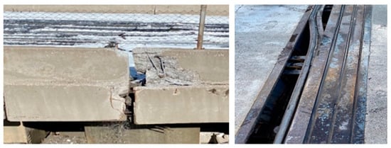
Figure 5.
Railing and expansion joint damages on Nurdağı Şehitler Viaduct.
The Nurdağ viaduct was located in the Nurdağ district. The total length of Nurdağ Viaduct is 266 m and it has five spans. The viaduct consists of two parallel parts: a prestressed reinforced concrete prefabricated beam section and composite steel box beam section. The nearest station to Nurdağ Viaduct is the TK2712 station. The PGA values for this station during the M7.7 earthquake have been provided above. The distance from the TK2712 station to the viaduct is 3.38 km. It can be seen from Figure 6 that during the M7.7 earthquake, the Nurdağı Viaduct experienced concrete spalling in the middle pier column where concrete and steel deck joints are connected. Additionally, there was an opening in the expansion joint, collision damage to New Jersey elements, and crushing in the steel girder at the abutment support. The horizontal components caused longitudinal movements in the bridge deck girders, while the vertical component resulted in vertical impact effects on the girders. The horizontal components of the earthquake were effective in causing these damages.

Figure 6.
Concrete spalling, girder crushing, New Jersey collision, and expansion joint opening damages on the Nurdağı Viaduct.
The Nurdağı Turgut Özal Viaduct, situated in the Nurdağ district, has a total length of 424 m and features a steel box section deck with five spans. The nearest station to the Turgut Özal Viaduct is the TK2712 station. The PGA values for this station during the M7.7 earthquake are mentioned above. The distance of the TK2712 station from the viaduct is 1.40 km. Figure 7 illustrates the separation in the abutment steel plates and the opening in the expansion joint of the Turgut Özal Viaduct due to the longitudinal movements.

Figure 7.
Separation in the abutment steel plate and opening in the expansion joint in the Turgut Özal Viaduct.
The Başpınar Viaduct is located in the Nurdağ district. It has a total length of 310 m and consists of eight spans. The viaduct was constructed using prestressed reinforced concrete prefabricated beams. The nearest station to the Başpınar Viaduct is the TK2712 station. The PGA values for this station during the M7.7 earthquake are explained above. The distance of the TK2712 station from the viaduct is 1.50 km. Figure 8 shows that during the M7.7 earthquake, the E-W component caused the Başpınar Viaduct to experience openings and pounding in the expansion joints, damage to the deck above the cap beam, and damage to the precast facade and New Jersey elements.

Figure 8.
Earthquake-induced damage on the Başpınar Viaduct.
The Büyükkarasu Bridges, located in the city of Hatay, consist of two parallel bridges, with each having a total length of 65 m. The prestressed simple girder bridge on the right side with four spans was constructed in 2014 and the cast-in-place simple girder bridge on the left side with four spans was built in 1989. In the TK3142 station located in Kırıkhan district, the PGAH values recorded during the M7.7 earthquake in the E-W and N-S directions are 739.29 cm/s2 and 651.69 cm/s2, respectively. The PGAV value recorded in the vertical direction is 456.90 cm/s2. The shear wave velocity of the foundation soil at the TK3142 station is 539 m/s [25]. The distance from the TK3142 station to the epicenter of the M7.7 earthquake is 106.49 km and the distance from the station to the bridge is 3.91 km. In the aftermath of the M7.7 earthquake, due to the lateral movement, it is seen from Figure 9 that the shear keys on the left side of the old Büyükkarasu bridge sustained damage and the deck shifted by approximately 10 cm at the joint.

Figure 9.
Shear key and deck joint shifting damages on the Büyükkarasu Bridge.
The Afrin Bridges, located in the city of Hatay, each with a total length of 84 m, consist of two parallel bridges, one on the left and one on the right. The bridge on the right is a 5-span prestressed simple beam bridge, constructed in 2014. The bridge on the left is a 5-span cast-in-place simple beam bridge, built in 1987. At TK3133 station in Reyhanlı district, during the M7.7 earthquake, the recorded PGAH values in the E-W and N-S directions are 147.22 cm/s2 and 221.41 cm/s2, respectively. The PGAV value in the vertical direction is 87.60 cm/s2. The shear wave velocity of the foundation soil at the TK3133 station is 377 m/s [25]. The epicenter-to-station distance for the M7.7 earthquake at the TK3133 station is 123.47 km and the station-to-bridge distance is 7.30 km. After the M7.7 earthquake, it was observed that transverse movement and damage occurred at the joint of the left bridge deck and the rubber pads on the right bridge experienced longitudinal sliding, as depicted in Figure 10.

Figure 10.
Joint transverse movement and rubber pad sliding on the Afrin Bridge.
The Hitit (Demirköprü) Bridge, located in the city of Hatay, consists of two parallel bridges for both directions, each with a total length of 61.8 m. The bridge on the right is a three-span prestressed simple beam bridge, constructed in 2010. The bridge on the left is a three-span prestressed simple beam bridge, built in 1990. At TK3124 station in Antakya district, during the M7.7 earthquake, the recorded PGAH values in the E-W and N-S directions are 638.32 cm/s2 and 572.63 cm/s2, respectively. The recorded PGAV value in the vertical direction is 578.08 cm/s2. The shear wave velocity of the foundation soil at the TK3124 station is 283 m/s [25]. The epicenter-to-station distance for the M7.7 earthquake at the TK3124 station is 140.11 km and the station-to-bridge distance is 16.46 km. As can be seen in Figure 11, rotations and openings occurred in the expansion joint damage at the three abutments of the bridge. Additionally, extensive and deep settlements and cracks were observed behind the abutments in the asphalt and approach embankment due to soil liquefaction.

Figure 11.
Expansion joint and liquefaction damage on the Hitit Bridge.
The Deve Geçidi Viaduct, located on the Diyarbakır-Ergani State Road, has a length of 572 m and features 14 spans. It is a prestressed reinforced concrete simple beam bridge, which was constructed in 2019. In Diyarbakır province, at the TK2101 station, during the M7.7 earthquake, the recorded PGAH values in the E-W and N-S directions are 71.42 cm/s2 and 77.08 cm/s2, respectively. The PGAV value in the vertical direction is 33.53 cm/s2. The shear wave velocity of the foundation soil at the TK2101 station is 519 m/s [25]. The epicenter-to-station distance for the M7.7 earthquake is 287.35 km and the station-to-viaduct distance is 18.16 km. The only observed damage resulting from the longitudinal effect of the M7.7 earthquake was the expansion joint opening damage, as indicated in Figure 12.

Figure 12.
Expansion joint damage on Deve Geçidi Viaduct.
The Adıyaman Göksu Bridge, located in the city of Adıyaman, consists of two parallel parts, A and B. The A part, built in 1983, is a reinforced concrete simple beam bridge, while the B part, constructed in 2012, is a reinforced concrete prestressed simple beam bridge. Both the A and B parts of the bridge have 11 spans with a span length of 19.95 m, a total length of 226 m, and a width of 8.50 m. In Nurhak district, at the TK4631 station, during the M7.6 earthquake, the recorded PGAH values in the E-W and N-S directions are 388.61 cm/s2 and 337.39 cm/s2, respectively. The recorded PGAV value in the vertical direction is 610.04 cm/s2. The shear wave velocity of the foundation soil at the TK4631 station is 543 m/s [25]. The epicenter-to-station distance for the M7.6 earthquake at the TK4631 station is 21.43 km and the station-to-bridge distance is 27.73 km. Figure 13 shows that the Adıyaman Göksu Bridge suffered internal and external shear key damage, as well as expansion joint openings, due to the horizontal components of the M7.6 earthquake.

Figure 13.
Shear key and expansion joint opening damages on the Adıyaman Göksu Bridge.
3.2. Failures at Expansion Joints with Viscous Dampers
The seismic performances of the Tohma Bridge, equipped with viscous dampers at the expansion joints, and the Adana 15 July Martyrs Bridge, fitted with Shock Transmission Unit (STU) devices at the bearings during the 2023 Kahramanmaraş earthquakes, are examined and assessed in the following sections.
3.2.1. Tohma Bridge
The Tohma Bridge was constructed in 2021 and situated on the Tohma Stream within the boundaries of Malatya province, precisely at coordinates 38.23858° E and 38.50476° N. The superstructure of the bridge was designed as a steel composite continuous beam with reinforced columns. The total length of the bridge with nine spans is 517.50 m. The bridge consists of two edge piers (A1 and A2) and eight central piers (P1–P8). The span lengths are 34.5 m between A1 and P1, 69 m between P2 and P6 (six spans), and 34.5 m between P7–P8 and P8–A2 (two spans). Some views from the bridge are shown in Figure 14.

Figure 14.
Views from Tohma Bridge.
The I3000 profile was used as a steel girder, with top and bottom flange widths and thicknesses of 1250 mm and 55 mm. The reinforced concrete slab thickness is 280 mm. The bridge deck concrete class is C45 (fc28 = 45 MPa), while the concrete class for the central and edge piers is C30 (fc28 = 30 MPa). The material grade for the steel girders is S355N (fy = 355 MPa, allowable tensile and compressive strength = 0.55fy). The steel plates on the bridge deck have a maximum thickness of 120 mm. For the reinforced concrete elements of the bridge, S420 steel (fy = 420 MPa) has been selected.
The site soil class was determined as ZC, which has a shear wave velocity ranging from 360 to 760 m/s [26]. The edge piers are founded on observed conglomerate units from the surface. Since conglomerate units provided sufficient strength and experienced less load compared to the central piers, shallow foundations were used for the edge piers. Due to the central piers resting on alluvial layers, bored piles with a diameter (D) of 120 cm were placed at 3D (360 cm) intervals. Each central pier has 20 piles underneath. The pile lengths in the central piers vary between 14 m and 34 m.
In bridge analyses, considering the ZC soil class, a 5% damped design spectrum was used for the 1000-year return period. The maximum spectral acceleration values for short (SS) and 1.0-s (S1) periods were determined to be 1.117 g and 0.729 g, respectively. The PGA value calculated at the bridge location for the 1000-year earthquake is 0.568 g.
Modular expansion joints, comprising multiple components, were employed on the bridge abutments. There are a total of four fluid viscous dampers, with two each at bridge piers A1 and A2, located at the expansion joints. A fluid viscous damper, which is a Maurer Hydraulic Damper (MHD2500/600), was integrated into the units in the longitudinal viaduct direction. This system allows unrestrained longitudinal movement of the superstructure concerning the substructure, accommodating effects such as creep, shrinkage, and temperature variations. The maximum load capacity of the viscous dampers used on the bridge is 2500 kN, with a longitudinal displacement capacity of ±300 mm, a maximal velocity of 860 mm/s, and a damping coefficient of 2557 kNs/m. Moreover, sliding pot bearings and fixed pot bearings were installed on the top of the piers. The friction coefficient for the sliding pot bearings used on the bridge is 0.06 and the displacement capacity was selected as 300 mm, compatible with the fluid viscous dampers. The load capacity for the fixed pot bearings used on piers P4 and P5 was determined to be 4890 kN.
The fluid viscous dampers and pot bearings were designed to exhibit behavior close to elastic for the 1000-year seismic level. During the 2023 Kahramanmaraş earthquake sequences, the bridge was subjected to strong near-fault pulse-type motions and Tohma Bridge experienced earthquake-induced damage at the hydraulic dampers mounted on the edge piers at the Malatya direction, as well as at the expansion joints and numerous pot bearings. Disconnections and locking have occurred at the connections of the fluid viscous dampers. The pot bearings suffered complete failure with their parts dislocated and ejected from the bearing pedestals. Figure 15 illustrates the damage to the expansion joint, pot bearings, and dampers on the Tohma Bridge.

Figure 15.
Earthquake-induced damage to the Tohma Bridge.
The Tohma Bridge was subjected to two mainshocks (M7.7 and M7.6) and numerous aftershock ground motions. To assess the damage behavior of the Tohma Bridge during the M7.7 and M7.6 mainshocks, two strong ground motion stations, TK4406 and TK4412, which are closest to the bridge, were selected. The TK4406 station is located at a distance of 143.07 km from the M7.7 earthquake epicenter and 70.17 km from the M7.6 earthquake epicenter. The TK4412 station is situated at a distance of 176.60 km from the M7.7 earthquake epicenter and 99.89 km from the M7.6 earthquake epicenter. Despite both stations being quite far from the epicenters of the M7.7 and M7.6 earthquakes, they are in proximity to the EAF and its segments. Figure 16 depicts the position of the Tohma Bridge, the epicenters of the earthquakes (M7.7 and M7.6), fault lines, and the locations of the strong ground motion stations that recorded significant data.

Figure 16.
Location of the Tohma Bridge, the epicenters of earthquakes, the fault lines, and the strong ground motion stations.
Figure 17 displays recorded accelerations versus time and spectra at the TK4406 station for the horizontal (E-W and N-S) and vertical (U-D) directions during the M7.7 and M7.6 earthquakes. The TK4406 station is situated approximately 29 km to the southwest of the bridge. The shear wave velocity of the ground at the TK4406 station is 815 m/s [25]. The shear wave velocity of the bridge site ranges from 360 to 760 m/s [26]. It can be observed from Figure 17a that the recorded accelerations have significant high-frequency content. This indicates that the accelerations contain rapid fluctuations over short time intervals, which can have considerable implications for the dynamic response of structures subjected to such ground motions. The Peak Ground Accelerations (PGAs) for the M7.7 and M7.6 mainshocks at the TK4406 station are 132.92 cm/s2 and 382.47 cm/s2 in the E-W direction and 109.47 cm/s2 and 444.75 cm/s2 in the N-S direction, respectively. In the vertical (U-D) direction, the PGAs are 49.71 cm/s2 and 284.86 cm/s2, respectively. The PGAs recorded at the TK4406 station for the M7.7 and M7.6 earthquakes are lower than the 1000-year return period earthquake design value of 557.21 cm/s2. However, during the M7.6 earthquake, the PGAs recorded in the N-S direction are close to the bridge design acceleration values.

Figure 17.
Acceleration time histories and spectra recorded at the TK4406 station during the M7.7 and M7.6 Kahramanmaraş earthquakes.
The acceleration spectra with 5% damping for the M7.7 and M7.6 earthquakes at the TK4406 station are presented in Figure 17b for both horizontal directions (E-W and N-S) and the vertical direction (U-D), along with the bridge design curve for a 1000-year return period. When comparing the horizontal acceleration spectra calculated from the M7.7 and M7.6 ground motions recorded at the TK4406 station to the smoothed bridge design acceleration spectrum, it is observed that the spectral accelerations in the E-W, N-S, and U-D directions at TK4406 station for both M7.7 and M7.6 earthquakes are generally lower than the design spectrum accelerations. However, the spectral values of the recorded E-W and N-S components during the M7.6 earthquake exceed the design spectral values in the short period range of 0.1 s and 0.2 s. The maximum spectral accelerations calculated for the M7.6 earthquake in the E-W and N-S directions within the 0.1 s to 0.2 s range are 1496.34 cm/s2 and 1345.45 cm/s2, respectively. The design spectrum’s maximum spectral acceleration is 1129.13 cm/s2. During the M7.6 earthquake, the maximum spectral accelerations recorded in the E-W and N-S directions are 33% and 19% greater than the maximum values of the design spectrum, indicating that the bridge was subjected to high acceleration values within these period ranges. Furthermore, in the vertical direction, the peak spectral acceleration was 985.70 cm/s2, which is significant because it suggests that the bridge girders lifted off their supports and repeatedly slammed back down, contributing significantly to the observed damage.
Velocity–time histories at the TK4406 station for the M7.7 and M7.6 earthquakes in the horizontal (E-W and N-S) and vertical (U-D) directions are depicted in Figure 18. The figures clearly show the substantial velocity pulses in the ground velocity components. The Peak Ground Velocities (PGVs) for the M7.7 and M7.6 mainshocks at the TK4406 station are 27.35 cm/s and 35.01 cm/s in the E-W direction and 13.12 cm/s and 21.34 cm/s in the N-S direction, respectively. In the vertical direction, the PGVs for M7.7 and M7.6 mainshocks are 11.70 cm/s and 19.03 cm/s, respectively. When examining the temporal variations in velocities recorded at the TK4406 station during the M7.7 and M7.6 earthquake series, it is observed that velocity values close to the PGVs are repeated numerous times throughout the duration of the earthquake records. The PGVs recorded at the TK4406 station for the M7.7 and M7.6 earthquakes are smaller than the maximum velocity capacity of the viscous dampers installed on the bridge, which is 86 cm/s. However, it can be stated that the fault induced significant directivity and fling effects, resulting in notable velocity pulses and permanent tectonic deformations. These effects caused damage to pot bearings and viscous damper devices.
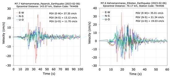
Figure 18.
Time histories of the velocities recorded at the TK4406 station during the M7.7 and M7.6 Kahramanmaraş earthquakes.
Displacement time histories at the TK4406 station for the M7.7 and M7.6 earthquakes in the horizontal (E-W and N-S) and vertical (U-D) directions are illustrated in Figure 19. The figures clearly depict the substantial pulse effects in the displacement records. The Peak Ground Displacements (PGDs) for the M7.7 and M7.6 mainshocks at the TK4406 station are 39.44 cm and 24.19 cm in the E-W direction and 20.15 cm and 20.11 cm in the N-S direction, respectively. In the vertical direction, the PGDs are 10.04 cm and 9.18 cm, respectively. The absolute maximum recorded displacements at the TK4406 station for the M7.7 and M7.6 earthquakes do not exceed the maximum relative displacement capacity of 30 cm for the viscous dampers and pot bearings, except for the maximum ground displacement of 39.44 cm recorded in the E-W direction during the M7.7 earthquake. It can be stated that the substantial movements of the superstructure relative to the substructure during the Kahramanmaraş earthquakes resulted in excessive translation of the bearings and dampers.

Figure 19.
Time histories of the displacements recorded at the TK4406 station during the M7.7 and M7.6 Kahramanmaraş earthquakes.
Arias intensity graphs for the effective durations of the ground motion records in the E-W, N-S, and U-D directions recorded at the TK4406 station during the M7.7 and M7.6 earthquakes are presented in Figure 20. Arias Intensity graphs provide valuable insights into the energy content and intensity of ground shaking during an earthquake. It can be generally stated that Arias intensity graphs of the E-W, N-S, and U-D components have similar shapes for each earthquake event. For the M7.7 earthquake, the effective duration in the records falls in the range of 20–70 s, while for the M7.6 earthquake, it is in the range of 15–35 s for E-W, N-S, and U-D directions. The M7.7 earthquake has a longer effective duration than the M7.6 earthquake, meaning that the shaking is more prolonged and more energy is delivered to the structure. The Arias intensity plots of the E-W, N-S, and U-D components are close to each other for each earthquake record.

Figure 20.
Arias intensity graphs at the TK 4406 station for the M7.7 and M7.6 earthquakes.
The second station selected to assess the behavior of the Tohma Bridge during earthquakes is the TK4412 station. The TK4412 station is located to the north of the bridge, approximately 11 km away. The shear wave velocity of the ground at the TK4412 station is 360 m/s. Time histories of acceleration measurements recorded at the TK4412 station during the M7.7 and M7.6 earthquakes are presented in Figure 21a for the horizontal (E-W and N-S) and vertical (U-D) directions. The PGAs for the M7.7 and M7.6 mainshocks at the TK4412 station are 68.15 cm/s2 and 126.02 cm/s2 in the E-W direction and 63.05 cm/s2 and 157.81 cm/s2 in the N-S direction, respectively. In the vertical direction, the PGAs for the M7.7 and M7.6 earthquakes are 54.21 cm/s2 and 79.02 cm/s2, respectively. The PGAs recorded at the TK4412 station during the M7.7 and M7.6 earthquakes are significantly lower than the 557.21 cm/s2 value considered for the 1000-year return period earthquake in the bridge design.

Figure 21.
Acceleration time histories and spectra recorded at the TK4412 station during the M7.7 and M7.6 Kahramanmaraş earthquakes.
Acceleration spectra graphs with 5% damping for the M7.7 and M7.6 earthquakes at the TK4412 station are presented in Figure 21b for the two horizontal directions (E-W and N-S) and the vertical (U-D) direction, along with the bridge design curve for a 1000-year return period. As can be seen from Figure 21b, the spectral accelerations recorded in the E-W, N-S, and U-D directions at the TK4406 station for the M7.7 earthquake are significantly lower than the design spectral accelerations. They are below the design spectral values along the period range. However, the spectral accelerations recorded at the TK4412 station have effective values in the range of 0.2 s to 2 s. Considering that the bridge’s periods fall within this range, it can be stated that the M7.7 and M7.6 earthquakes caused significant demands on the bridge.
The velocity–time histories at the TK4412 station for the M7.7 and M7.6 earthquakes in the horizontal (E-W and N-S) and vertical (U-D) directions are depicted in Figure 22. The figures clearly show the substantial velocity pulses in the ground velocity components at the TK4412 station. The PGVs for the M7.7 and M7.6 mainshocks at the TK4412 station are 47.47 cm/s and 28.63 cm/s in the E-W direction and 26.75 cm/s and 38.83 cm/s in the N-S direction, respectively. In the vertical direction, the PGVs for M7.7 and M7.6 earthquakes are 27.11 cm/s and 29.02 cm/s. The PGVs recorded at the TK4412 station for the M7.7 and M7.6 earthquakes are smaller than the maximum velocity capacity of the viscous damper, which is 86 cm/s. However, an examination of the velocity–time histories recorded at the TK4412 station during the M7.7 and M7.6 earthquake series, as shown in Figure 22, reveals that velocity values close to the peak ground velocities (PGVs) are repeated numerous times throughout the duration of the earthquake records.
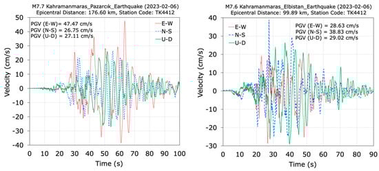
Figure 22.
Time histories of the velocities recorded at the TK4412 station during the M7.7 and M7.6 Kahramanmaraş earthquakes.
Recorded displacements versus time at the TK4412 station from the M7.7 and M7.6 earthquakes are displayed in Figure 23 for the horizontal (E-W and N-S) and vertical (U-D) directions. The PGDs for the M7.7 and M7.6 mainshocks at the TK4412 station are 44.63 cm and 16.64 cm in the E-W direction and 28.66 cm and 28.37 cm in the N-S direction, respectively. In the vertical direction, the PGDs for both mainshocks are 24.59 cm and 25.63 cm. The absolute maximum recorded displacements at the TK4412 station for the M7.7 and M7.6 earthquakes exceeded the maximum relative displacement capacity of 30 cm for the viscous damper and pot bearings, particularly in the E-W direction during the M7.7 earthquake. This condition can be attributed to triggering damage in the expansion joint, viscous dampers, and pot bearings.
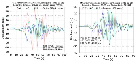
Figure 23.
Time histories of the displacements recorded at the TK4412 station during the M7.7 and M7.6 Kahramanmaraş earthquakes.
The Arias intensity graphs for the effective durations of the ground motion records in the E-W, N-S, and U-D directions recorded at the TK4412 station during the M7.7 and M7.6 earthquakes are presented in Figure 24. For the M7.7 earthquake, the effective duration in the records of E-W and N-S directions falls in the range of 30–80 s, while it is in the range of 30–65 s for the M7.6 earthquake. In the records of the U-D direction, the effective duration for the M7.7 earthquake is in the range of 30–85 s and it falls in the range of 28–80 s for the M7.6 earthquake. The M7.7 earthquake record at the TK4412 station has a longer effective duration than the M7.6 earthquake. The Arias intensity plots for the E-W, N-S, and U-D components differ from each other.

Figure 24.
Arias intensity graphs at the TK 4412 station for the M7.7 and M7.6 earthquakes.
3.2.2. Adana 15th July Martyrs Bridge
The Adana 15 July Martyrs Bridge is a highway and railway bridge located over the Seyhan River in the city of Adana, Turkey. The bridge connects the Seyhan and Yüreğir districts. During the 2023 Kahramanmaraş earthquakes, the construction of the bridge was in its final stages (Figure 25). The total length of the bridge with 23 spans is 1668.90 m, with 786.90 m consisting of a post-tensioned reinforced concrete box section and 882 m composed of a continuous steel box-section girder system. The bridge, with a total width of 38.85 m, serves as a 6-lane roadway, divided into three lanes for each direction of traffic. Additionally, there is a railway track with one line on the bridge.
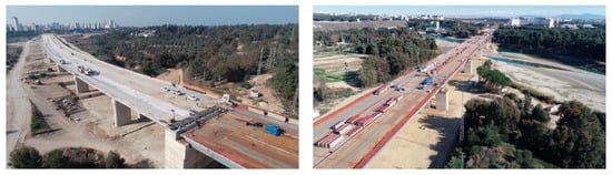
Figure 25.
Views and sections of the Adana 15 July Martyrs Bridge.
In the reinforced concrete section, elastomeric bearings were used. Between the steel superstructure and the piers, there are pot bearings. The movements of both central and edge pier bearings of continuous steel box-section girders were restricted in the transverse direction for both service and seismic loads. The bearings can only move longitudinally. In the steel bridge section, LRN1000X160 pot bearings with a diameter of 1000 mm were utilized at the edge piers and LRN1200X192 pot bearings with a diameter of 1200 mm were used at the central piers. The heights of the pot bearings are 160 mm and 192 mm. The allowable horizontal displacements of the pot bearings at the edge and central piers are 320 mm and 390 mm, respectively. The effective horizontal stiffnesses of the pot bearings at the edge and central piers are 6540 kN/m and 7850 kN/m, respectively. Their maximum vertical load capacities of the edge and central piers are 1610 kN and 2550 kN, respectively. In addition to pot bearings in the steel section, Shock Transmission Unit (STU) devices were used to ensure that all central pier bearings were restrained in the longitudinal direction during seismic events. STU devices allow free longitudinal movement of the superstructure relative to the substructure due to creep, shrinkage, and temperature and lock up under high-speed movement to engage.
The deck, central, and edge piers have a concrete class of C50 (fc28 = 50 MPa). The material grade for the steel elements used to span the openings is S355J2G3 (fy = 355 MPa, allowable tensile and compressive strength = 0.55fy). The steel plates in the bridge have a maximum thickness of 63 mm. The material grade for the steel in the reinforced concrete elements is S420 (fy = 420 MPa). The tensile strength of the prestressing strands in the reinforced concrete elements is 1860 MPa.
The bridge foundation consists of alluvial and conglomerate units. An average shear wave velocity (Vs30) of 1010 m/s was determined for a depth of 30 m and soil class ZB was selected for the analyses (ABP, 2018). Bored piles with a diameter of 120 cm were used at axes P21 and P22. All bridge piles have sockets, with a pile length of 26.0 m at axis P21 and 28.50 m at axis P22.
The seismic design spectrum was defined for horizontal ground motion spectral acceleration values corresponding to return periods of 2475 and 475 years (ABP, 2018). For a 2475-year return period, the maximum spectral acceleration values for short (Ss) and 1.0-second (S1) periods were determined as 1.064 g and 0.256 g, respectively. In the case of an earthquake with a 475-year return period, the maximum spectral acceleration values for short (Ss) and 1.0-s (S1) periods were obtained as 0.525 g and 0.13 g, respectively. For the 475-year earthquake, the PGA value at the bridge location is 0.3 g. The dominant periods calculated from the theoretical modal analysis of the bridge model in the longitudinal and transverse directions are 1.318 s and 0.248 s, respectively [27].
The Adana 15 July Martyrs Bridge experienced the effects of the first and second primary seismic events (M7.7 and M7.6). It can be seen from Figure 26 that no damage was observed on the Adana 15 July Martyrs Bridge during the inspections following the 2023 Kahramanmaraş earthquake sequences.
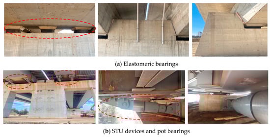
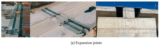
Figure 26.
Views from the elastomeric and pot bearings, shock transmission unit devices, and expansion joints of the Adana 15 July Martyrs Bridge.
To investigate the seismic performance of the Adana 15 July Martyrs Bridge during the 2023 Kahramanmaraş seismic events, the TK0118 station, which is closest to the bridge, was selected. The TK0118 station is located at a distance of 155.36 km from the M7.7 earthquake and 205.81 km from the M7.6 earthquake. The shear wave velocity of the soil at the TK0118 station is 946 m/s [3]. Figure 27 provides a visual representation of the Adana 15 July Martyrs Bridge’s location, the epicenters of the M7.7, M7.6, and M6.4 earthquakes, and the TK0118 station that recorded significant data.

Figure 27.
Location of the Adana 15 July Martyrs Bridge, the epicenters of earthquakes, and the strong ground motion station.
The TK0118 station is situated approximately 1.0 km northwest of the bridge. The shear wave velocity of the soil beneath the TK0118 station is 946 m/s [25], while the average shear wave velocity of the bridge foundation soil is 1010 m/s [27]. The time histories of accelerations recorded at the TK0118 station during the M 7.7 and M 7.6 earthquakes are depicted in Figure 28a, showing data for both horizontal (E-W and N-S) and vertical (U-D) directions. The PGAs for the M 7.7 and M 7.6 mainshocks at the TK0118 station are 38.01 cm/s2 and 23.67 cm/s2 in the E-W direction and 49.24 cm/s2 and 27.27 cm/s2 in the N-S direction, respectively. In the vertical direction, the PGAs are 23.21 cm/s2 and 24.15 cm/s2, respectively. It is noteworthy that the PGAs recorded at the TK0118 station for the M 7.7 and M 7.6 earthquakes are significantly lower than the PGA, 294.30 cm/s2, considered in the design of the bridge for a 475-year return period earthquake.

Figure 28.
Acceleration time histories and spectra recorded at the TK0118 station during the M7.7 and M7.6 Kahramanmaraş earthquakes.
Acceleration spectra with 5% damping for the M 7.7 and M 7.6 earthquakes at the TK0118 station are presented in Figure 28b, specifically for the two horizontal directions (E-W and N-S) and the vertical (U-D) direction. As can be seen from Figure 28b, the spectra exhibit significant acceleration within the period range of 0.2 s to 3 s. The theoretical dominant periods of the bridge in the longitudinal and transverse directions are 1.318 s and 0.248 s, respectively, which fall within the 0.2 s to 3 s range in the acceleration spectrums in Figure 28b. The calculated spectral accelerations at the TK0118 station for the M7.7 and M7.6 earthquakes in the E-W, N-S, and U-D directions are notably lower than the design spectral acceleration values corresponding to 2475-year short and 1-s periods, which are 1043.78 cm/s2 and 251.14 cm/s2, respectively. The recorded spectral values are also considerably lower than the design spectral acceleration value of 515.03 cm/s2 for the short period corresponding to a 475-year earthquake. However, it is worth noting that the recorded spectral values are close to 127.53 cm/s² for the 1-s period corresponding to a 475-year return period earthquake.
The time histories of the velocities at the TK0118 station from the M7.7 and M7.6 earthquakes are plotted in Figure 29 for the horizontal (E-W and N-S) and vertical (U-D) directions. The large velocity pulses of the components of the velocities can be clearly seen in Figure 29. PGVs for M7.7 and M7.6 mainshocks at the TK0118 station are 14.51 cm/s and 25.63 cm/s in the E-W direction and 18.76 cm/s and 11.79 cm/s in the N-S direction, respectively. In the vertical direction, the PGVs are 10.88 cm/s and 12.10 cm/s, respectively. Upon examining the temporal changes in the recorded velocities at the TK0118 station during the M7.7 and M7.6 earthquake sequences, it is evident that velocity values closely resembling the PGV values are recurrently observed throughout the duration of the earthquakes.
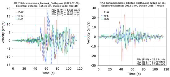
Figure 29.
Velocity–time histories recorded at the TK0118 station during the M7.7 and M7.6 Kahramanmaraş earthquakes.
Recorded displacements versus time at the TK0118 station from the M 7.7 and M7.6 earthquakes are plotted in Figure 30 for the horizontal (E-W and N-S) and vertical (U-D) directions. PGDs for M7.7 and M7.6 mainshocks at the TK0118 station are 13.69 cm and 32.12 cm in the E-W direction and 33.63 cm and 9.13 cm in the N-S direction, respectively. In the vertical direction, the PGDs are 10.75 cm and 12.14 cm, respectively. At the TK0118 station, the absolute maximum recorded displacements for the N-S component during the M7.7 earthquake and the E-W component during the M7.6 earthquake exceed the maximum displacement capacity of the pot bearings at the abutment piers, which is 32 cm. However, it is worth noting that the recorded ground displacement values are smaller than the displacement capacity of pot bearings at the central piers, which is 39 cm.
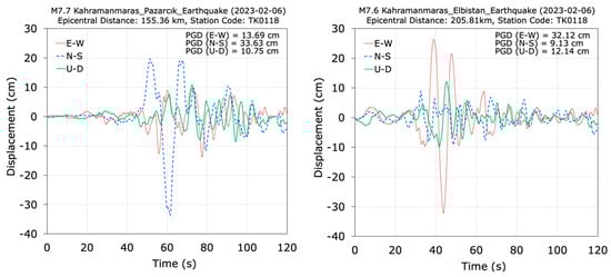
Figure 30.
Displacement time histories recorded at the TK0118 station during the M7.7 and M7.6 Kahramanmaraş earthquakes.
Arias intensity graphs for the effective durations of the recorded ground motion in the E-W, N-S, and U-D directions at the TK0118 station during the M7.7 and M7.6 earthquakes are provided in Figure 31. For the M7.7 earthquake, the effective duration intervals in the records of E-W, N-S, and U-D directions are 30–100 s, 40–100 s, and 30–100 s, respectively. For the M7.6 earthquake, the effective duration intervals in the records of E-W, N-S, and U-D directions are 35–90 s, 30–90 s, and 20–90 s, respectively. It can be stated that the M7.7 and M7.6 earthquakes recorded at the TK0118 station have similar effective durations. The Arias intensity plots for the E-W, N-S, and U-D components differ from one another.

Figure 31.
Arias intensity graphs at the TK0118 station for the M7.7 and M7.6 earthquakes.
4. Conclusions
A comprehensive seismic evaluation of the failure mechanisms of bridge expansion joints without viscous dampers caused by the 2023 Kahramanmaraş earthquakes (M7.7 and M7.6) was conducted, and the seismic performance of bridge expansion joints equipped with viscous dampers and shock transmission unit devices was investigated using the strong ground motion data in this study. The following summarizes some of the results obtained from the study:
- Damage issues observed in bridges during the 2023 Kahramanmaraş earthquakes include pounding and openings in expansion joints, sliding between girders and bearings, settlement at supports, steel plate crushing, concrete pouring in columns, interior and exterior shear key failures, cracking in abutments, transverse joint offsets, and liquefaction in foundations;
- The most prevalent types of damage on the bridge expansion joints without viscous dampers are pounding and openings in expansion joints and interior and exterior shear key failures;
- Disconnections and locking occurred at the connections of the fluid viscous dampers, while the pot bearings suffered a complete failure, with their components dislocated and ejected from the bearing pedestals;
- The maximum displacement capacities of the fluid viscous dampers and the pot bearings were exceeded during the earthquakes;
- It is thought that the main cause of the damage was the proximity of the fault rupture to the bridges and the successive impact of strong near-fault earthquake sequences; These factors led to very high horizontal and vertical ground accelerations, velocities, and displacements, resulting in significant damage to the bridges;
- When designing bridge expansion joints, viscous dampers, shock transmission units, pot bearings, and shear keys in high seismicity regions, it is crucial to consider the back-to-back and long-period pulse effects of near-fault ground motions;
- To ensure the sustained functionality of bridges, it is vital to conduct regular inspections and maintenance of the expansion joints.
Author Contributions
Conceptualization, A.B.; methodology, A.B., Y.T., M.A., E.H., C.E.V. and T.Y.Y.; software, A.B., Y.T., M.A., E.H., C.E.V. and T.Y.Y.; validation, A.B., Y.T., M.A., E.H., C.E.V. and T.Y.Y.; formal analysis, A.B., Y.T., M.A., E.H., C.E.V. and T.Y.Y.; investigation, A.B, Y.T., M.A., E.H., C.E.V. and T.Y.Y.; resources, A.B, Y.T., M.A., E.H., C.E.V. and T.Y.Y.; data curation, A.B.; writing—original draft preparation, A.B., Y.T., M.A., E.H., C.E.V. and T.Y.Y.; writing—review and editing, A.B., Y.T., M.A., E.H., C.E.V. and T.Y.Y.; visualization, A.B., Y.T., M.A., E.H., C.E.V. and T.Y.Y.; supervision, A.B. All authors have read and agreed to the published version of the manuscript.
Funding
The authors declare that no funds, grants, or other support were received during the preparation of this manuscript.
Data Availability Statement
The data presented in the study are available on request from the corresponding author.
Acknowledgments
The authors wish to extend their heartfelt gratitude to the General Directorate of Highways (KGM) and Disaster and Emergency Management Presidency (AFAD).
Conflicts of Interest
The authors declare that they have no conflicts of interest.
References
- Miari, M.; Choong, K.K.; Jankowski, R. Seismic pounding between bridge segments: A state-of-the-art review. Arch. Comput. Methods Eng. 2021, 28, 495–504. [Google Scholar] [CrossRef]
- Shrestha, B.; Hong Hao, H.; Bi, K. Devices for protecting bridge superstructure from pounding and unseating damages: An overview. Struct. Infrastruct. Eng. 2017, 13, 313–330. [Google Scholar] [CrossRef]
- Gao, K.; Yuan, W.; Cao, S.; Pang, Y. Seismic performance of cable-sliding modular expansion joints subject to near-fault ground motion. Lat. Am. J. Solids Struct. 2015, 12, 1397–1414. [Google Scholar] [CrossRef]
- Chouw, N.; Hao, H. Seismic design of bridge structures with allowance for large relative girder movements to avoid pounding. Bull. N. Z. Soc. Earthq. Eng. 2009, 42, 75–85. [Google Scholar] [CrossRef]
- Feng, M.Q.; Kim, J.-M.; Shinozuka, M.; Purasinghe, R. Viscoelastic Dampers at Expansion Joints for Seismic Protection of Bridges. J. Bridge Eng. 2000, 5, 67–74. [Google Scholar] [CrossRef]
- Zhu, P.; Abe, M.; Fujino, Y. Modelling three dimensional non-linear seismic performance of elevated bridges with emphasis on pounding of girders. Earthq. Eng. Struct. Dyn. 2002, 31, 1891–1913. [Google Scholar] [CrossRef]
- Ruangrassamee, A.; Kawashima, K. Control of nonlinear bridge response with pounding effect by variable dampers. Eng. Struct. 2003, 25, 593–606. [Google Scholar] [CrossRef]
- Li, J.; Peng, T.; Xu, Y. Damage investigation of girder bridges under the Wenchuan earthquake and corresponding seismic design recommendations. Earthq. Eng. Eng. Vib. 2008, 7, 337–344. [Google Scholar] [CrossRef]
- Chouw, N.; Hao, H. Significance of SSI and non-uniform near-fault ground motions in bridge response I: Effect on response with conventional expansion joint. Eng. Struct. 2008, 30, 141–153. [Google Scholar] [CrossRef]
- Chouw, N.; Hao, H. Significance of SSI and non-uniform near-fault ground motions in bridge response II: Effect on response with modular expansion joint. Eng. Struct. 2008, 30, 154–162. [Google Scholar] [CrossRef]
- Chouw, N.; Hao, H. Pounding damage to buildings and bridges in the 22 February 2011 Christchurch earthquake. Int. J. Prot. Struct. 2012, 3, 123–139. [Google Scholar] [CrossRef]
- Guo, T.; Liu, J.; Zhang, Y.; Pan, S. Displacement monitoring and analysis of expansion joints of long-span steel bridges with viscous dampers. J. Bridge Eng. 2015, 20, 04014099. [Google Scholar] [CrossRef]
- Sun, Z.; Zhang, Y. Failure mechanism of expansion joints in a suspension bridge. J. Bridge Eng. 2016, 21, 05016005. [Google Scholar] [CrossRef]
- Mahjoubi, S.; Maleki, S. Pipe dampers as passive devices for seismic control of isolated bridges. Struct. Control. Health Monit. 2016, 24, e1869. [Google Scholar] [CrossRef]
- Li, X.; Shi, Y. Seismic design of bridges against near-fault ground motions using combined seismic isolation and restraining systems of LRBs and CDRs. Shock. Vib. 2019, 2019, 4067915. [Google Scholar] [CrossRef]
- Khedmatgozar Dolati, S.S.; Mehrabi, A.; Khedmatgozar Dolati, S.S. Application of viscous damper and laminated rubber bearing pads for bridges in seismic regions. Metals 2021, 11, 1666. [Google Scholar] [CrossRef]
- Guo, W.; Li, J.; Guan, Z.; Chen, X. Pounding performance between a seismic-isolated long-span girder bridge and its approaches. Eng. Struct. 2022, 262, 114397. [Google Scholar] [CrossRef]
- Meng, D.; Yang, M.; Sun, T.; He, X.; Chouw, N. Seismic-induced poundings in highway and high-speed railway bridges: A state-of-the-art review. Struct. Infrastruct. Eng. 2023, 1–15. [Google Scholar] [CrossRef]
- Eraky, A.; Sharabash, A.M.; El-Feky, M.H. Efficiency of shape memory alloy seismic restrainers for several conditions of bridge joints. Frat. Ed Integrità Strutt. 2023, 64, 104–120. [Google Scholar] [CrossRef]
- MTA. Türkiye Active Fault Maps; General Directorate of Mineral Research and Exploration: Ankara, Turkey, 2023. [Google Scholar]
- Bayraktar, A.; Akköse, M.; Taş, Y.; Ventura, C.E.; Yang, T.Y. Monitored seismic performance assessment of cable-stayed bridges during the 2023 Kahramanmaraş earthquakes (M7.7 and M7.6). J. Civil. Struct. Health Monit. 2024. [Google Scholar] [CrossRef]
- AFAD. February 06, 2023 Kahramanmaraş (Pazarcık and Elbistan) Earthquakes Field Study Preliminary Assessment Report. Disaster and Emergency Management Presidency (AFAD), Ankara, Turkey, 2023. Available online: https://deprem.afad.gov.tr/assets/pdf/Arazi_Onrapor_28022023_surum1_revize.pdf (accessed on 10 August 2023). (In Turkish)
- USGS. The M7.8 and M7.5 Kahramanmaraş Earthquake Sequence Struck near Nurdağı, Turkey (Türkiye) on February 6 2023; United States Geological Survey: Reston, VA, USA, 2023. [Google Scholar]
- SBB. 2023 Kahramanmaraş and Hatay Earthquakes Report. Presidency of Strategy and Budget, Ankara, Turkey. 2023. Available online: https://www.sbb.gov.tr/wp-content/uploads/2023/03/2023-Kahramanmaras-and-Hatay-Earthquakes-Report.pdf (accessed on 7 July 2023).
- AFAD. Disaster and Emergency Management Presidency (AFAD), Ankara, Turkey. 2023. Available online: https://tadas.afad.gov.tr (accessed on 10 August 2023).
- TBP. Tohma Bridge Project; UBM Inc.: Ankara, Turkey, 2015. [Google Scholar]
- ABP. Adana 15 July Martyrs Bridge Project; Prizma Engineering Inc.: Istanbul, Turkey, 2018. [Google Scholar]


Disclaimer/Publisher’s Note: The statements, opinions and data contained in all publications are solely those of the individual author(s) and contributor(s) and not of MDPI and/or the editor(s). MDPI and/or the editor(s) disclaim responsibility for any injury to people or property resulting from any ideas, methods, instructions or products referred to in the content. |
© 2024 by the authors. Licensee MDPI, Basel, Switzerland. This article is an open access article distributed under the terms and conditions of the Creative Commons Attribution (CC BY) license (https://creativecommons.org/licenses/by/4.0/).