Article

Study on the Impact of Deep Foundation Pit Construction on Nearby Elevated Structures—Case Study

1
School of Civil Engineering, Hubei Engineering University, Xiaogan 432000, China
2
Wuhan Bohong Construction Group Co., Ltd., Wuhan 430050, China
3
Wuhan Municipal Engineering Design & Research Institute Co., Ltd., Wuhan 430023, China
4
School of Urban Construction, Wuhan University of Science and Technology, Wuhan 430081, China
*
Authors to whom correspondence should be addressed.
Buildings 2024, 14(8), 2541; https://doi.org/10.3390/buildings14082541
Submission received: 12 July 2024 / Revised: 5 August 2024 / Accepted: 16 August 2024 / Published: 18 August 2024
(This article belongs to the Section Architectural Design, Urban Science, and Real Estate)

Abstract

:
Urbanization and population concentration in China’s major cities drive high land utilization demands, affecting nearby bridges during underground construction. Foundation pit construction alters the internal forces, deformation, and displacement of bridge piles. To understand these impacts and assess excavation support rationality, a case study was conducted on an ultra-deep foundation pit near an elevated ring road bridge in Wuhan. Considering the engineering geological conditions of the project site, construction sequence, and traffic load on the bridge, a three-dimensional finite element model was established to simulate the impact of foundation pit excavation on the elevated structure. And through an analysis of tracked monitoring data from the construction site, comparisons were also made with the simulation results. The findings of this case study indicated that throughout the entire construction phase of the foundation pit, the maximum horizontal and vertical displacements of the bridge foundation structure caused by the construction are 2.98 mm and −1.75 mm, respectively; the maximum change rate of the bending moment in the bridge structure due to the foundation pit construction is 6.3%, while the change in the axial forces is small, and completely within the safety control standards for bridge structure displacement. By analyzing the monitoring data over three stages within one year after the completion of the foundation pit, it is shown that the bridge structure gradually tends to stabilize. Additionally, due to soil consolidation, its displacement shows uniform rebound and tends to stabilize. The research findings provide valuable reference points for the design and construction of similar deep foundation pit projects.

1. Introduction

In urban transportation, overpasses and elevated bridges have become vital components. Due to limited ground space and the need to accommodate modern traffic demands [1], the construction of elevated bridges has increased, providing more convenient and faster traffic routes [2]. With rapid economic development, countries worldwide have significantly increased their infrastructure investments, leading to a booming bridge construction industry. The total number and length of bridges worldwide are increasing dramatically. In China, the rapid development and construction of elevated bridges have made them integral to highways, railways, and urban transportation [3,4,5]. Consequently, the protection and maintenance of these bridges have become imperative.
Engineering practice has shown that the excavation of foundation pits induces changes in the internal stress of the soil, leading to adverse geotechnical phenomena such as pit collapse and sliding [6,7,8]. The soil layers in foundation pits are complex, with anisotropic mechanical and physical properties. Even if the pile foundations are well designed [9,10,11] according to regulations, if the excavation method is inappropriate or the pit walls are not promptly and properly treated, there is still a high risk of wall instability, bottom heave, and the displacement of engineering piles [12,13]. During the construction of the cut-off curtain in foundation pit engineering, the cutting or mixing of the in situ soil reduces the strength of the surrounding soil. Drilling and grouting piles release soil pressure and pore water pressure, which can lead to hole collapse and subsequently affect the stress state of the soil around the elevated structure [14]. The excavation of the foundation pit causes significant vertical unloading of the soil below the excavation surface, inevitably leading to soil rebound at the pit bottom [15,16,17]. Additionally, the retaining structure of the foundation pit, under the pressure of the surrounding soil, forces the structure below the excavation surface to displace inward, compressing the soil within the pit [18,19,20]. This increases the horizontal stress on the pit bottom soil and causes upward heaving, further affecting the stress state of the soil around the elevated structure. Also, the scale of unloading is a crucial factor influencing the displacement and stress fields around the elevated structure [21,22].
Even though there is a lot of research on the impact of foundation pit excavation on underground structures such as basements, tunnels, and utility corridors [23,24,25,26,27,28], studies on the effects of foundation pit excavation on adjacent elevated bridges are relatively scarce. As crucial components of urban transportation, elevated bridges are affected by the stress release in the surrounding soil during foundation pit excavation, which can impact the nearby structures’ foundations. Some researchers have addressed finite element simulation and onsite monitoring methods to study this issue; for instance, Liu et al. [29] conducted a numerical investigation to analyze the impact of deep foundation pit excavation on adjacent tunnel structures. They focused on understanding how the excavation affects the existing tunnel’s displacement and validated their three-dimensional model by comparing numerical simulations with field-measured ground settlement data. Matsumoto et al. [30] investigated the impact of a Statnamic test on pile foundations for a temporary road bridge over the Hokuriku railway line in Kanazawa, Japan. They found that the test had minimal effects on the surroundings. By performing a one-dimensional stress-wave analysis and using strain gauges to measure axial loads, they confirmed that the test’s predictions of pile load distribution and settlement were accurate, ensuring the safety of the pile foundations. Ayasrah et al. [31] conducted a series of numerical simulations to assess the effects of tunnel construction on adjacent pile cap foundations. Their study revealed that tunneling induces additional axial forces and bending moments, with significant impacts on pile responses depending on the tunnel’s depth and proximity to the pile foundations. Their findings underscore the critical role of the tunnel diameter and depth in influencing pile settlement and deflection. It can be seen that most of these studies are related to tunnel or road bridges. However, the displacement and mechanical impacts of foundation pits on relatively nearby urban elevated bridge structures are not well understood, particularly under adverse geological conditions such as deep soft soil; the long-term monitoring data after foundation construction also lack analysis [32,33,34]. Foundation pit excavation poses a significant threat to the safety of urban elevated bridge structures, and there is limited practical experience to draw upon.
This study examines a large foundation pit project near an elevated bridge structure and ramp in Wuhan. Using the MIDAS/GTS NX 2022R1 software, a three-dimensional numerical analysis model was constructed, and the modified Mohr–Coulomb constitutive model was applied to simulate the entire excavation support process. This study analyzes the displacement patterns of deep soil and support structures during foundation pit construction, deduces the displacement patterns of elevated bridge structures and pile foundations, and proposes targeted safety measures for foundation pit construction. The research findings provide valuable reference points for the design and construction of other transportation routes and similar deep foundation pit projects.

2. Project Overview

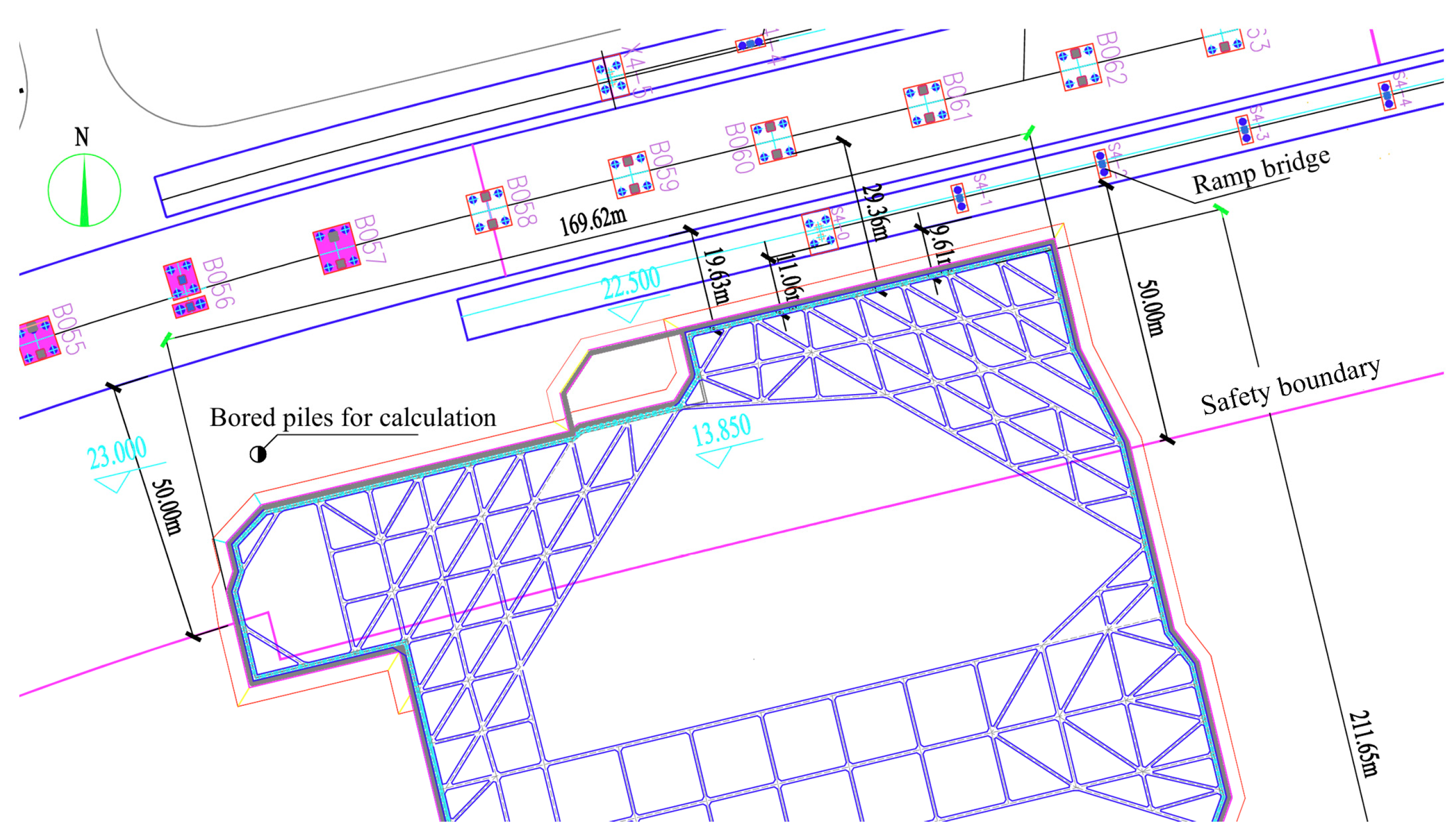
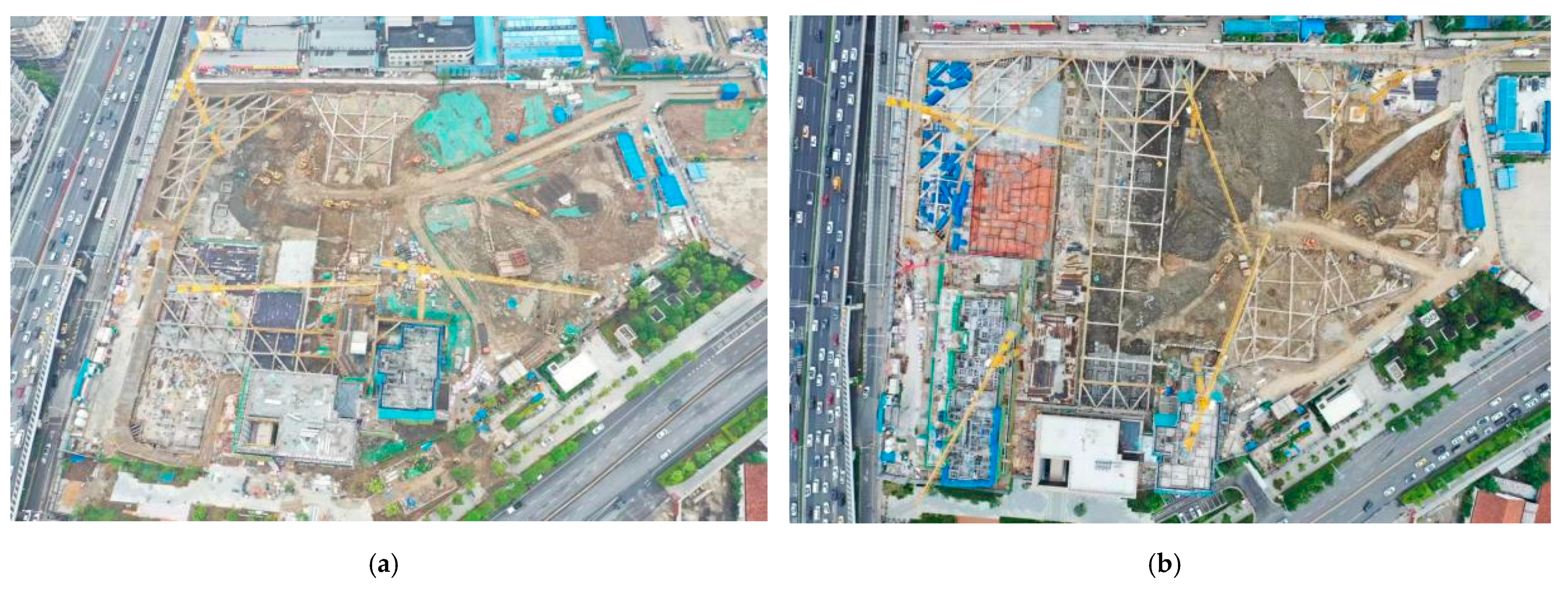
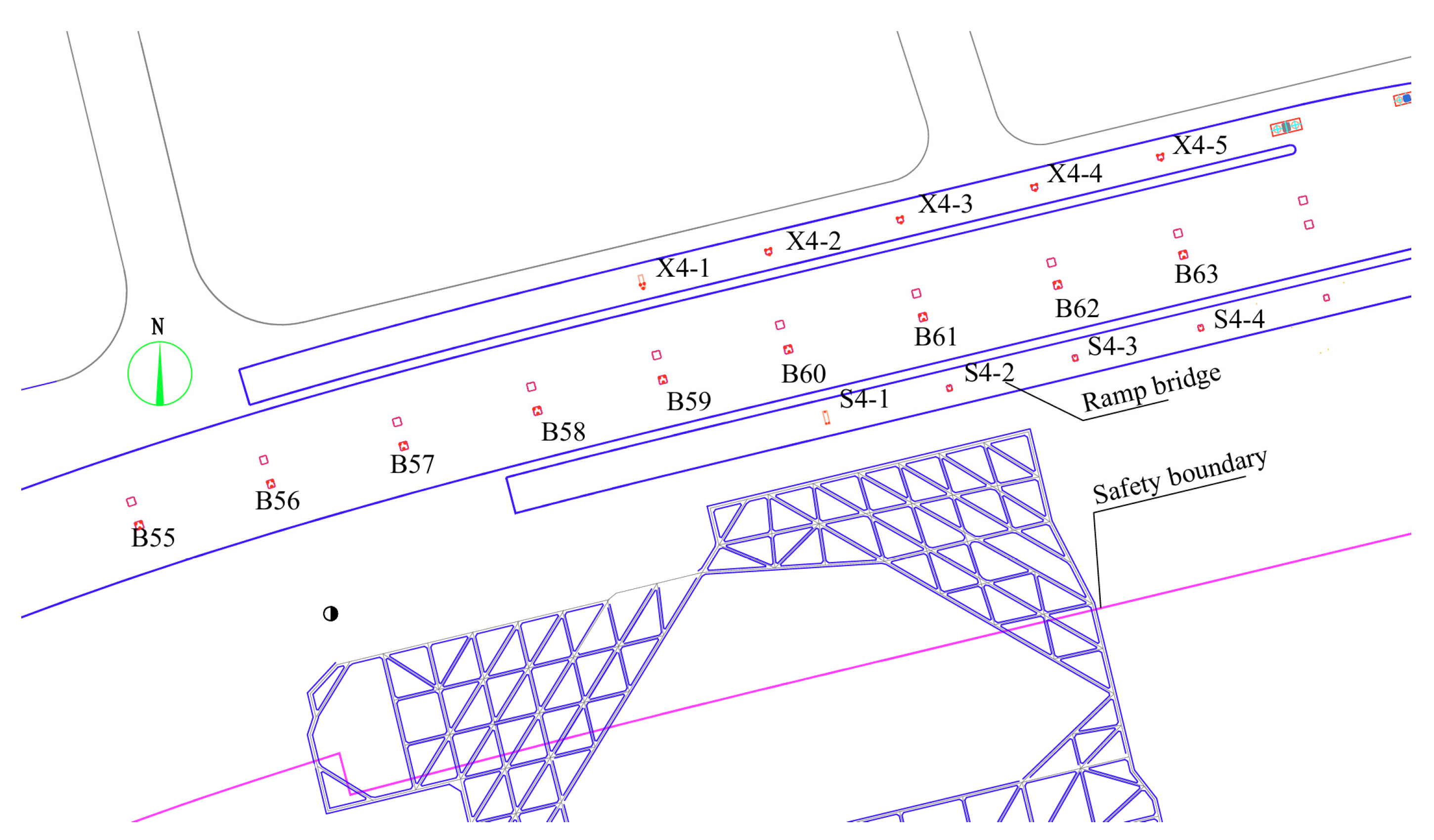
2.1. Project Profile

The project is located in Wuhan, a major city in Hubei Province, Central China. Wuhan has a high population density, which demands a high land utilization rate and extensive underground space excavation. The construction site before the excavation can be seen in Figure 1; the designed foundation pit construction is very close to the elevated bridge. The minimum horizontal clear distance between the inner edge of the foundation pit retaining piles and the ramp bridge piles is 11.06 m, and the minimum horizontal clear distance from the main bridge piles of the second elevated ring road is 29.36 m.
According to Article 3.0.2 of the Chinese Code “Code for Design of Urban Bridges” (CJJ 11-2011), the elevated structures involved in this project are classified as medium-sized urban bridges. Based on Article 19 of the local regulation “Wuhan Urban Bridge and Tunnel Safety Management Regulations”, the safety protection zone for medium-sized and larger urban bridges, as well as special structure urban bridges, includes the space beneath the bridge, which includes the land area within 50 m outside the vertical projection plane of the bridge. Therefore, the construction of this deep foundation pit may have a significant impact on the elevated bridge structure. Studying the patterns and extent of this impact is crucial for ensuring the smooth implementation of the project and can also provide valuable insights for similar foundation pit construction projects.
As for the elevated bridge, the piers are numbered B55 to B63 from west to east. The section between piers B55 and B58 consists of a 3 × 30 = 90 m prestressed concrete box girder, while the section between piers B58 and B63 consists of a 2 × 28 + 2 × 30 + 1 × 28 = 144 m prestressed concrete box girder. The foundations of piers B55 to B64 are drilled and grouted pile foundations, with pile lengths ranging from 58 to 67 m. The pile bases penetrate into the moderately weathered mudstone layer (corresponding to the moderately weathered mudstone in Section 2.2 (6-2)). These bridge piles are end-bearing friction piles. Each bridge pier has a single cap, with four to six drilled and grouted piles of 1.2/1.5 m in diameter beneath each cap. The material for the drilled and grouted piles is underwater C30 concrete [35].
As for the ramp bridge, the foundation piers consist of drilled and grouted pile foundations, with pile lengths ranging from 50 to 65 m. The pile bases penetrate into the moderately weathered mudstone layer (corresponding to the moderately weathered mudstone in Section 2.2 (6-2)). These bridge piles are end-bearing friction piles. Each bridge pier has a single cap, with two to four drilled and grouted piles of 1.2 m in diameter beneath each cap. The material for the drilled and grouted piles is underwater C30 concrete.
As for the foundation pit, the perimeter of the foundation pit is approximately 811 m, with a vertical excavation area of about 27,300 square meters. The ground elevation around the foundation pit ranges from 22.50 to 23.20 m. The design depth of the second basement level of the foundation pit is approximately 8.05 to 9.40 m, while the design depth of the first basement level is 4.6 to 5.3 m. The foundation pit utilizes bored piles, internal bracing for support, and slope unloading at the pile tops. In some areas of the first basement level, slope cutting and cantilever piles are used, while slope cutting is utilized at the junction between the first and second basement levels. Inside the foundation pit, a combination of a hanging cut-off curtain, open drainage, and depressurization dewatering is implemented.
The plan view of the relationship between the excavation pit and the bridge can be seen in Figure 2.
The northern side of the foundation pit is adjacent to an elevated bridge and the ramp leading to it. The relevant sections of the foundation pit near the urban elevated bridge structures are designated as segments N1-A-A1-B-C-C1. Other sections of the foundation pit are further from the urban elevated bridge structures and are not the focus of this analysis. The section of the foundation pit near the elevated bridge is located within the second basement level, with an excavation depth of 8.05 m. The soil layers on the sidewalls of the foundation pit, from top to bottom, consist of (1) miscellaneous fill, (2) silty clay, (3) silty clay with silt, and fine sand. The bottom of the foundation pit is primarily located within (3) the silty clay with silt and fine sand layers. Beneath these layers lie (4) silty sand with silty clay and fine silty sand layers.
Considering the characteristics of this project and experience from similar projects in Wuhan, the main support systems that can be used are pile and brace structures, pile and anchor structures, and sloped excavation methods. Due to the complex surrounding environment and limited site area, the pile and brace structure is preferred. Taking into account the excavation depth, strata conditions, and surrounding environment, the preferred support structure for the excavation is bored cast-in-place piles combined with a waterproof curtain and internal bracing. This ensures the safety of surrounding structures such as bridges. Additionally, to reduce construction costs, a combination of long and short piles will be used for the cast-in-place piles. The specific parameters are as follows. The support system consists of Φ900@1300 drilled and grouted piles combined with truss bracing. The short piles are 15.8 m long (including the crown beam), and the long piles are 17.8 m long (including the crown beam). Slope unloading is achieved with a slope ratio of 1:1.2. The slope surface is reinforced with an 80 mm thick shotcrete layer. Outside the support piles, a cut-off curtain made of Φ850@600 three-axis mixing piles, 15.2 m long, is used as a water-blocking and silt-stopping curtain.

2.2. Engineering Geology and Hydrogeological Conditions

The main special geotechnical features of this site (as shown in Figure 3) include the following layers:
(1)
Miscellaneous fill. This consists of recently deposited material that has not undergone self-weight consolidation and is classified as under-consolidated soil.
(2)
Layer (3-1) silty clay. It is soft soil, locally missing, highly compressible, with low strength and poor engineering properties. Its adverse impact on foundation pit support and pile formation should be considered. This layer is of medium sensitivity and under-consolidated; untreated soft soil below the foundation may lead to instability and uneven settlement.
(3)
Layer (3-2) silty clay with silt and fine sand interlayers. It has low strength and medium compressibility, with uneven distribution and anisotropic properties.
(4)
Unit layer (6) weathered rock. It softens when exposed to water.
The groundwater at this site can be categorized into three types:
(1)
The first type is perched water primarily found in the upper layer of miscellaneous fill (Layer 1). Its water level and volume fluctuate seasonally, mainly influenced by atmospheric precipitation and domestic wastewater infiltration, without a consistent free water level. During the survey, the stable water table depth was measured at 1.2 to 3.0 m, corresponding to elevations of 19.49 to 21.81 m. The perched water level varies between the top and bottom of the fill layer.
(2)
The second type is confined water present in the lower sand layer, which is hydraulically connected to the Yangtze River, and its water level directly correlates with the Yangtze River’s water level. There is no hydraulic connection between the first and second groundwater layers due to the intervening clay soil.
(3)
The third type is fissure water in the bedrock, primarily stored within bedrock fissures on the site. The overall water volume is small and uneven, with minimal impact on engineering structures. Only a few fissures in the bedrock are hydraulically connected to the confined water in the quaternary sand and gravel layer.

3. Three-Dimensional Finite Element Model and Calculating Conditions

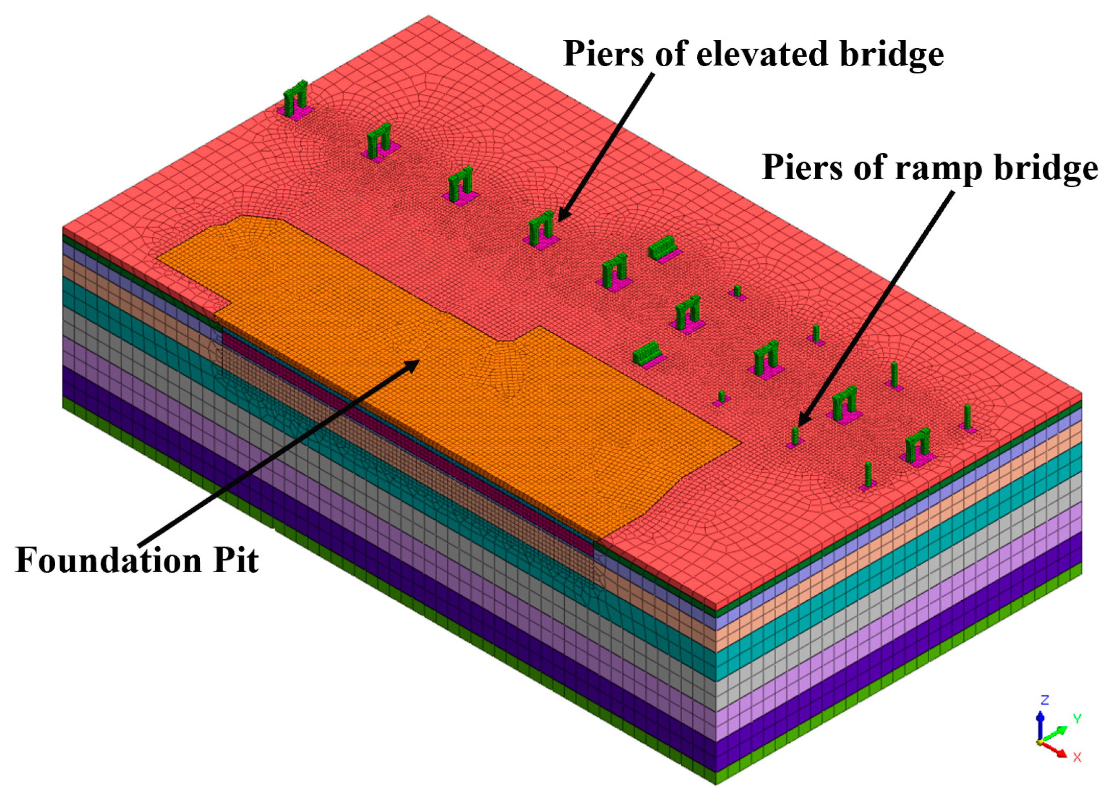
3.1. Model Design and Calculation Parameters

MIDAS GTS/NX (New eXperience of GeoTechnical Analysis System) 2022R1 is an advanced, general-purpose geotechnical analysis software developed using cutting-edge computer processing and analysis technology [36]. This software includes almost all analysis functions required for geotechnical and tunnel construction, such as stress analysis and permeability analysis during construction procedures. GTS/NX integrates the structural analysis capabilities of the general analysis program MIDAS/Civil with the geometric modeling and mesh generation functions of the pre- and post-processing program MIDAS/NX+, and adds specialized analysis functions tailored to the geotechnical and tunnel fields, thus meeting the analytical needs of this project.
The principle for controlling the model calculation range is that the boundary conditions should not significantly affect the results of the areas of interest. Based on previous research experience, for numerical calculations of foundation pits, the model extension range should be no less than three times the depth of the foundation pit. The overall model in this report includes the bridge structure and the proposed excavation pit, with a model calculation range approximately 300 m in length, 280 m in width, and 80 m in depth for the soil layer. The mesh consists of 232,092 elements and 149,019 nodes. In the model simplification, the design plan adopts different support forms based on the surrounding environmental variations. This calculation primarily focuses on the impact of pit excavation on the bridge; thus, the overall model uses the most adverse borehole near the bridge as the basis for determining the stratigraphic parameters. A three-dimensional calculation model is established, referencing the foundation pit and bridge construction drawings, without considering the influence of pits within pits. The axial view of the calculation model is shown in Figure 4 and the retaining structure and bridge pier are shown in Figure 5.
According to the geotechnical investigation report and existing engineering numerical simulation experience, the primary mechanical processes in this foundation pit excavation study include vertical unloading within the pit, lateral unloading outside the pit, nearly unchanged lateral stress beneath the excavated soil, reduced vertical stress, and unchanged vertical stress with reduced lateral stress in the soil outside the pit. Some of the calculation parameters are referenced in Table 1.
The bridge is modeled as a solid; the bridge piles are simulated using embedded beam elements; the foundation pit retaining structure is modeled using plate elements; and the internal supports, columns, and column piles are all simulated using beam elements. The concrete grade for the internal supports is C35, and for the column piles, it is C30. The dimensions and materials are detailed in Table 2. The foundation pit retaining piles are equivalent to a continuous slab structure based on the principle of equivalent stiffness, with bored piles of Φ900@1300 (diameter of 900 mm and spacing of 1300 mm) and an equivalent slab thickness of 0.667 m per meter.

3.2. Excavation Support and Boundary Simulation

This analysis primarily focuses on assessing the impact of the proposed foundation pit construction on the bridge structure and the displacement of the pit support structure. Since the analysis considers the incremental displacement caused by the pit excavation, the displacements induced by the construction of existing buildings and the initial stress field are reset to zero. Due to the coupling of dewatering through seepage in a steady-state analysis, the displacement and internal forces related to this step are not displayed in the results. Instead, these displacements are carried over to the next construction step. The analysis consists of ten construction steps, as detailed in Table 3.
In deep foundation pit construction, it is essential to consider the spatiotemporal effects and strictly follow the designed construction sequence. During excavation in soft soil foundation pits, it is important to reduce the spatial dimensions of each excavation step appropriately and minimize the exposure time of the retaining walls after each excavation step. Prolonged exposure of the pit bottom after excavation can also lead to accidents. This is because, after excavation, the foundation is unloaded, reducing the self-weight stress of the soil, and the soil’s elastic effect will cause certain rebound deformations (heaving) at the pit bottom. If the pit bottom remains exposed for too long, water accumulation in the pit will cause the clay to swell, exacerbating the rebound deformation.
The model constrains the Z-direction displacement at the bottom, Y-direction displacement at the front and back faces, and X-direction displacement at the left and right faces. The initial water head is set to 22.5 m, and the dewatering water head inside the foundation pit is set to 13.5 m. During the calculation process, a horizontal braking force of 165 kN from vehicles is considered, along with vertical loads from the bridge deck applied to the main bridge and ramp bridge pile foundations. Ground overloading is considered at 20 kPa.

4. Results and Discussion

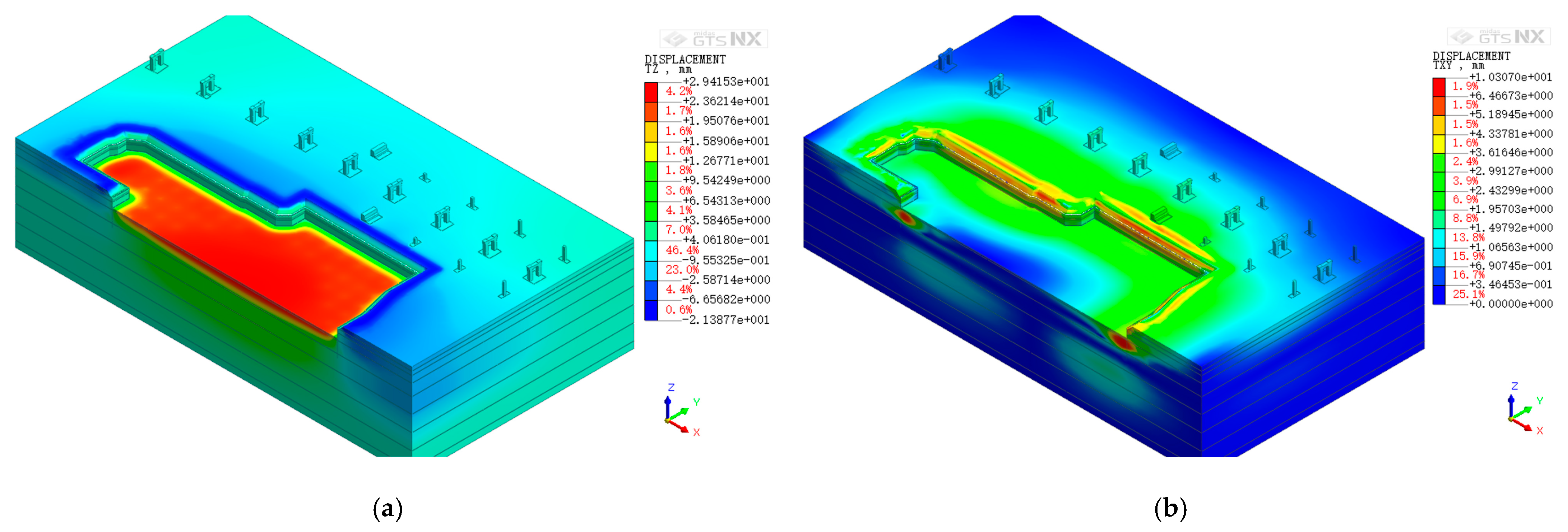
4.1. Displacement Analysis of the Total Structure

To verify whether the overall displacement of the foundation pit and the bridge meets the regulatory requirements, an analysis of the lateral and vertical displacement of the completed structure model after construction was conducted. As can be seen in Figure 6, the results indicate that the maximum overall horizontal displacement is 10.3 mm, and the maximum vertical displacement, specifically the maximum uplift at the bottom of the foundation pit, is 29.4 mm. Based on past engineering experiences, this uplift is usually due to unloading and can cause the kick-out failure of the retaining structure. The maximum settlement value is 21.4 mm. Both values satisfy the requirement in the specifications according to the local standards in Hubei Province, as outlined in the “Technical Specifications for Foundation Pit Engineering” (DB 42/T159-2012) [37]. The total displacement of the model meets the requirements after construction, indicating that the design of the retaining structure and the construction process of the foundation pit are reasonable.

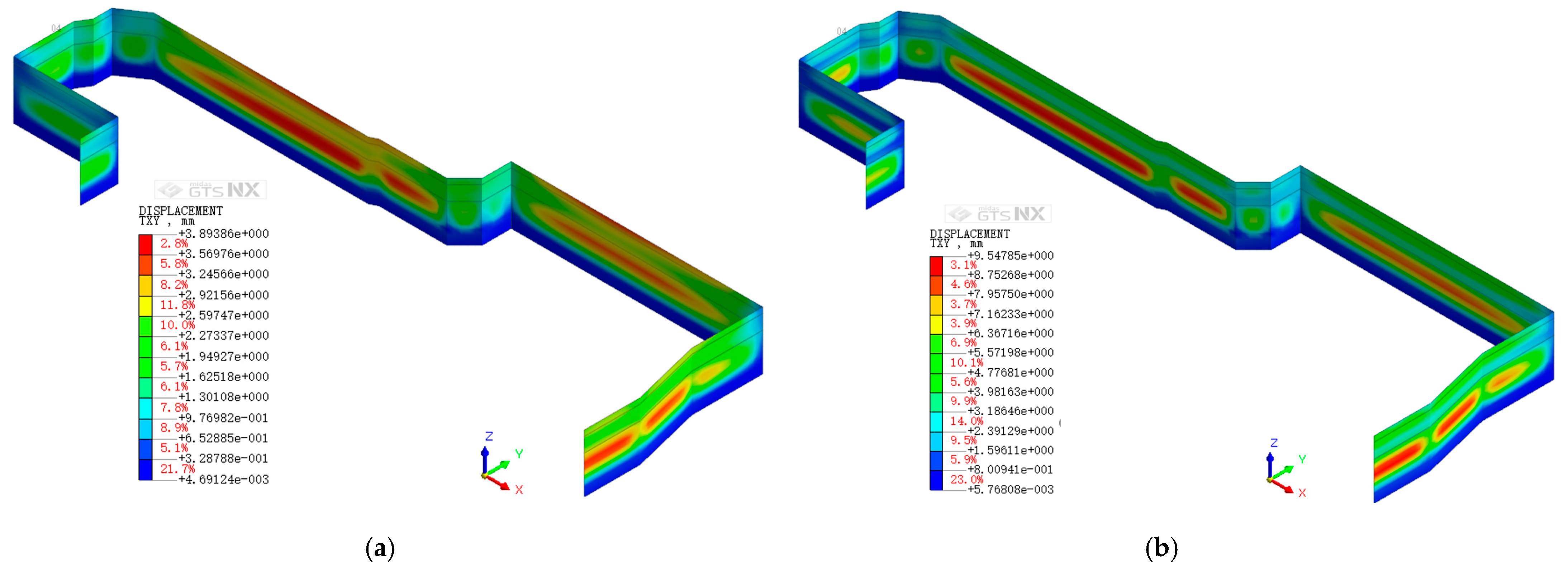
4.2. Displacement Analysis of Foundation Pit Support Structures

The analysis of the horizontal displacement of foundation pit retaining structures during excavation is crucial for ensuring the stability of the foundation pit, predicting potential risks, optimizing design schemes, and guiding construction operations. During the excavation of the foundation pit, disturbances to the surrounding soil are caused by the construction of retaining structures and the excavation itself. These disturbances lead to stress changes in the soil around and within the foundation pit. As the surrounding soil stress reaches a new equilibrium, the surrounding soil undergoes displacement. Due to the unloading inside the foundation pit and the imbalance of earth pressure on the inner and outer sides of the retaining structures, the retaining structures displace towards the inside of the foundation pit.
The horizontal displacement of the support structure in different construction procedures (procedure 7, 9, 10, and 11) are shown in Figure 7. The results reveal that during the construction of the foundation pit retaining structure, the structure initially starts to withstand lateral earth pressure. However, as the structure has not yet encountered soil release due to subsequent excavation, the displacement remains relatively minor. Numerical calculations show that during the first phase, the maximum horizontal displacement of the retaining structure measures 3.89 mm, indicating effective control of soil deformation and stable conditions during this procedure. As excavation progresses, the original stress equilibrium is disrupted, causing the soil to shift towards the pit and exert increased lateral pressure on the retaining structure. Consequently, the maximum displacement significantly rises to 9.55 mm, marking the most notable displacement among the four scenarios. This underscores the influence of soil stress release and redistribution during excavation on the retaining structure. Subsequent bracing operations enhance the stability of the retaining structure. Despite ongoing soil release effects from excavation, the retaining structure’s resistance to lateral pressure improves, resulting in a slight reduction in the maximum displacement. After the bracing is removed, the horizontal displacement of the retaining structure increases. Then, the pit nears its design depth, intensifying the effects of soil release and exerting maximum lateral pressure on the retaining structure. The peak displacement reaches 9.37 mm.
According to the local standard [37], the total horizontal displacement of the support structure in the pit must be kept within 25 mm. According to the finite element simulation results, the maximum horizontal displacement of the pit support structure is 9.55 mm, which is below the displacement control. Since the support structure in this project is deeply embedded, with negligible displacement at the pile bottoms, the impact of bottom uplift on the pit and surrounding environment is minimal.

4.3. Influence of the Foundation Construction on the Elevated Bridge

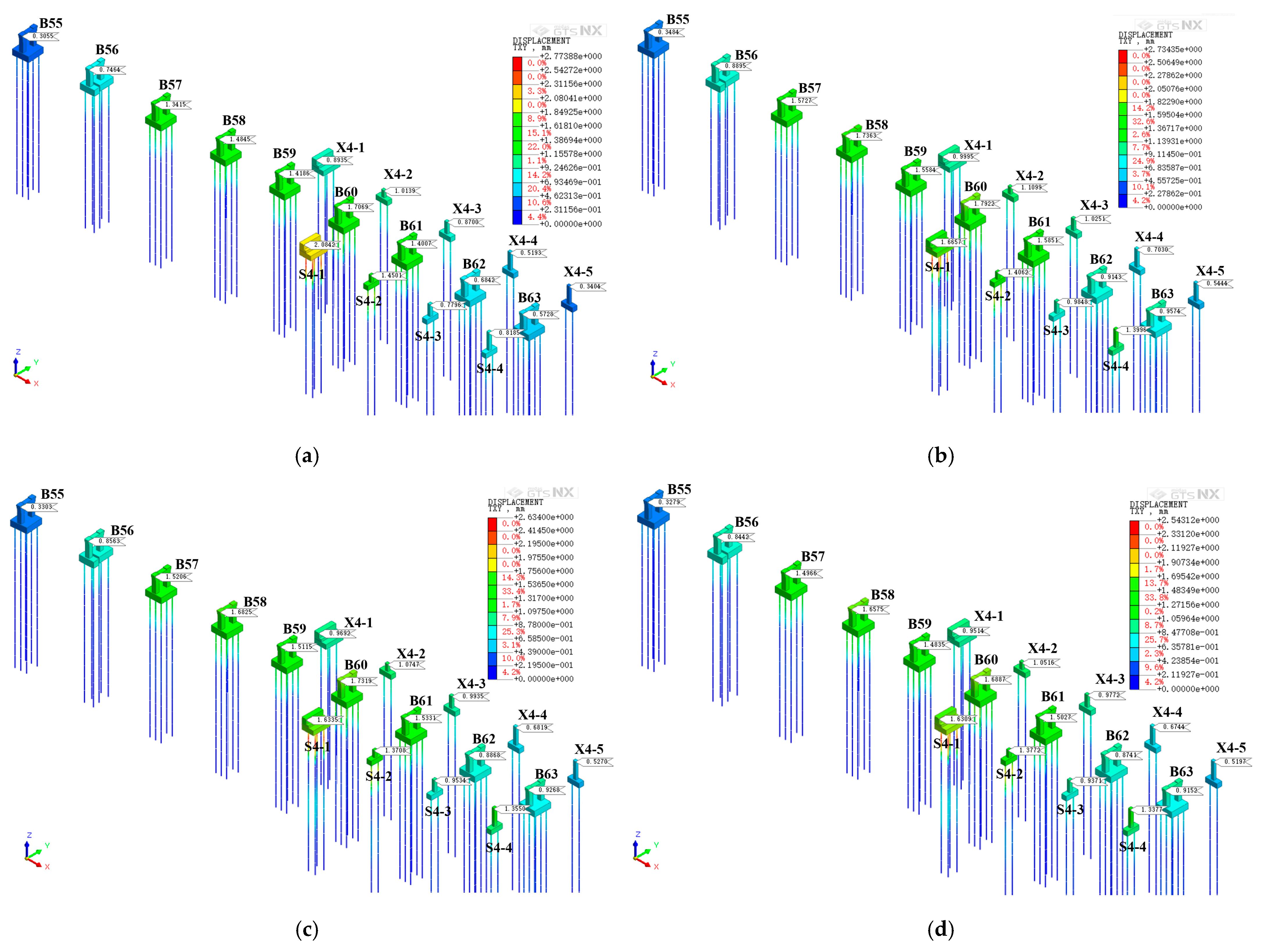
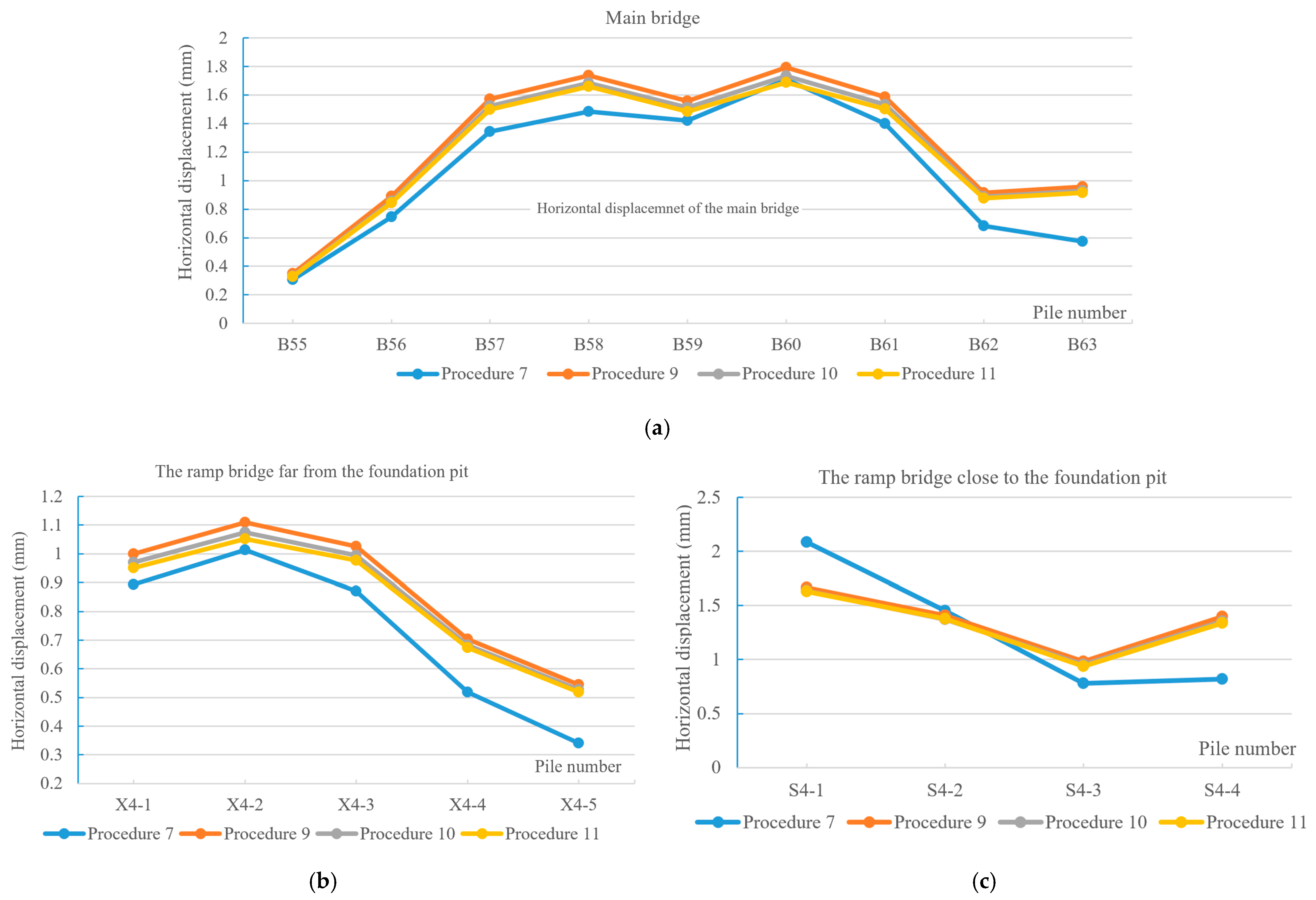
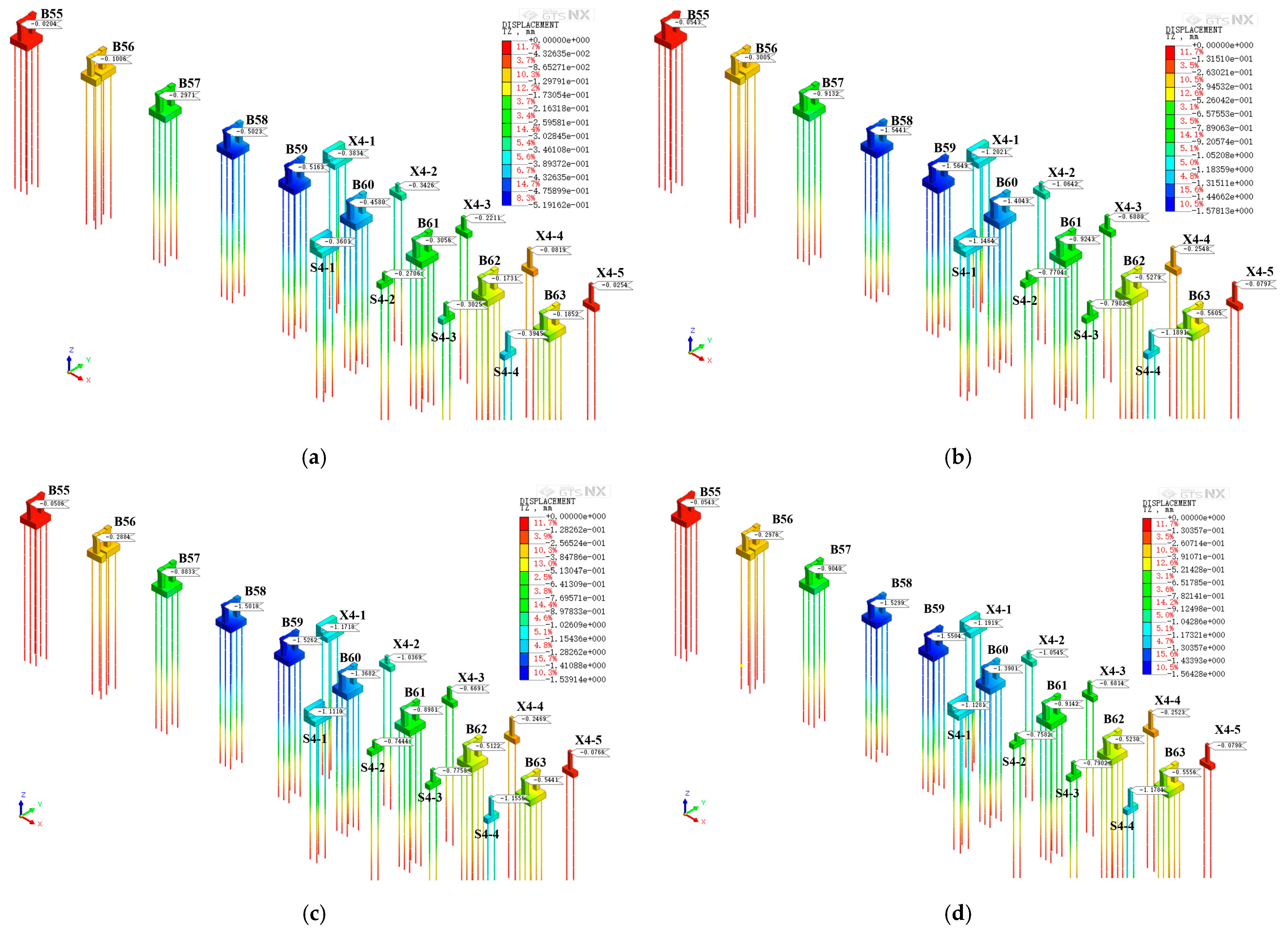
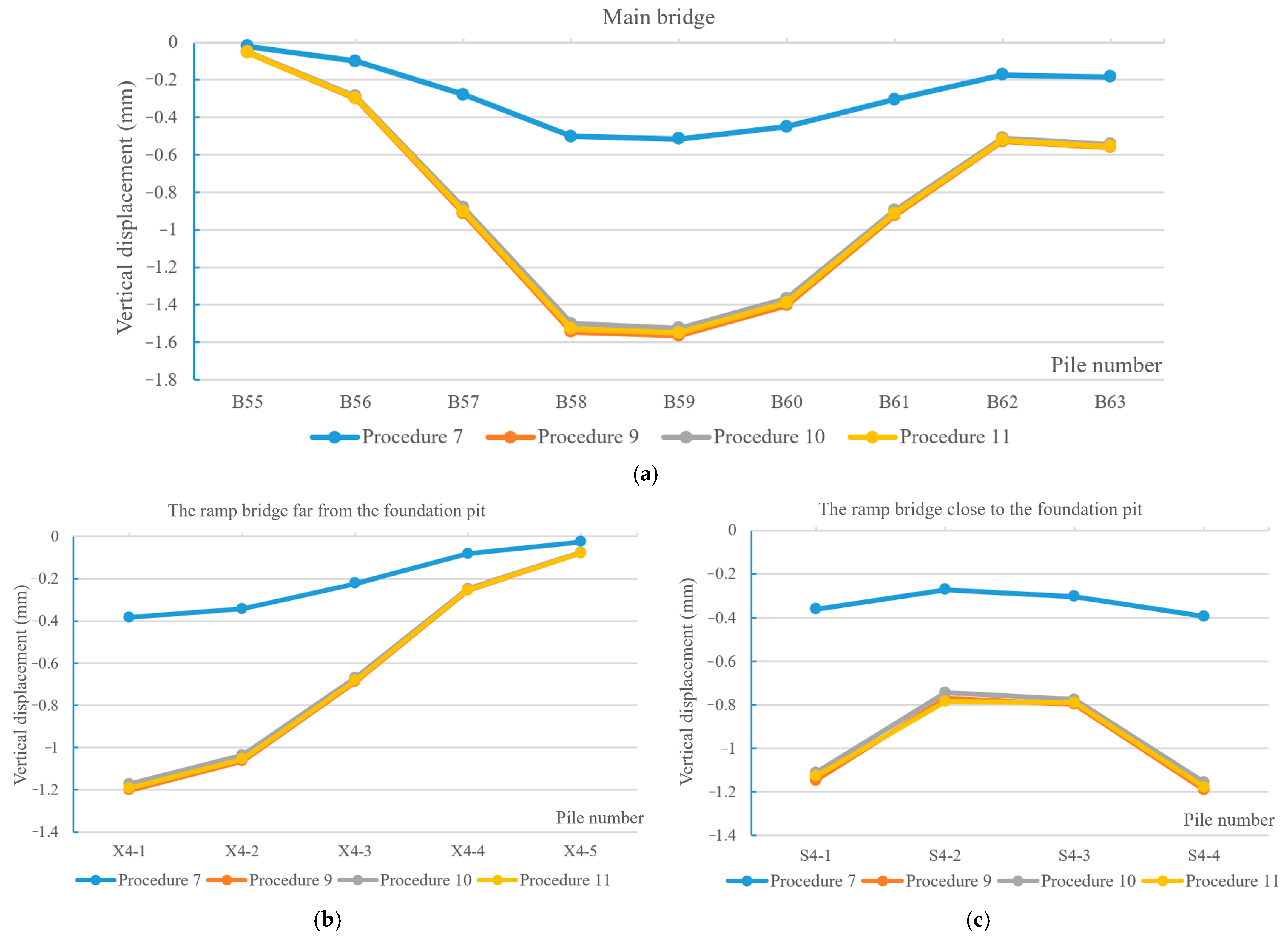
4.3.1. Displacements of the Elevated Bridge

Figure 8 shows the corresponding displacement contour maps of the whole bridge after different construction conditions. It can be seen that the excavation of the foundation pit significantly impacted the nearby elevated bridge, especially the closer ramp, causing horizontal displacements. The maximum displacement of the bridge structure is on the top of the pile. Before the foundation pit construction, the bridge structure was subjected to the original stress field. However, as the excavation progressed, the stress field of the elevated bridge altered. This led to stress release in the area where the bridge’s foundation is located, resulting in the displacement of the foundation. The upper part of the ramp foundation pile (S4-1) closest to the excavation exhibited the greatest displacement. In procedure 7, the weakest part near the contact surface of the bridge piers exhibited a maximum displacement of 2.774 mm. As the excavation continued to deepen, the maximum displacement of the pile became 2.734 mm. During the main construction phase, stress redistribution occurred within the soil, causing the displacement to gradually reduce to 2.634 mm and after completing procedure 11, the maximum displacement of the piles decreases to 2.543 mm.
The horizontal displacement in the top of the bridge piles close to the foundation side at different excavation procedures, plotted according to the bridge monitoring numbers in Figure 8, is shown in Figure 9. The figures also confirm an increasing trend in horizontal displacement from procedure 7 to procedure 9, attributed to bracing and soil stress redistribution. Subsequently, there is a slight decrease and regional stability in procedure 10 and procedure 11. Comparing variations in the measurement values along the bridge length reveals that the maximum horizontal displacement occurs at monitoring points B57–B60 on the main bridge. The displacement patterns at the far and near ramps correspond closely to those on the main bridge. Notably, the most significant displacement occurs at the near pit ramp; it can be seen that the data for S4-4 are relatively unique, which may be attributed to the relatively higher height of the pier at that location. This results in the model’s data monitoring points being positioned higher, making the horizontal displacement at the monitoring points more significantly affected by minor disturbances at the base. Also, the connection between the main bridge and the ramp bridge in the model and the real bridge are not totally the same; this minor difference has more impact on S4-4 than other places. There is an increase from S4-3 to S4-4, likely due to the interaction at the S4-4 and main bridge connection, limiting bridge displacement. Overall, the simulation results indicate that the excavation of the pit results in overall bridge displacement below the specified regulatory limits.
Figure 10 presents the vertical displacement curves of the pile foundations for the elevated bridge and ramp structures under different construction conditions of the foundation pit. It can be observed that all the vertical displacements are negative, indicating an overall sinking of the viaduct due to the excavation of the foundation pit. The vertical displacement of the bridge pile foundations primarily results from soil disturbance and stress release around the piles, causing the bridge structure to tilt toward the foundation pit. Additionally, the bridge piles rest on hard rock layers (see Figure 3) and have high stiffness; the settlement of the pile foundations due to excavation is relatively smaller. Thus, the monitoring point with the greatest vertical displacement is located at the main bridge, where the ramp near the foundation pit experiences slightly greater settlement than the distant ramps, but this is less than at piers B58, B59, and B60 of the main bridge. This may be because the midpoint of the excavation pit is located between B58 and B60, where the settlement effect is greatest, as confirmed by the greater settlement at X4-1 on the distant ramps. Comparing the settlement across the four procedures shows that settlement is minimal in the initial excavation procedure, gradually increasing with continued excavation, and slightly decreasing during the main construction and subsequent excavation phases, eventually stabilizing. The maximum settlement values out of all the piers are seen at B59, measuring −0.5163 mm, −1.5649 mm, −1.5262 mm, and −1.5299 mm respectively; the maximum of the total bridge structures is 1.578 mm, so all of these values are within permissible limits according to the regulations.
The vertical displacements of the bridge are shown in Figure 11. A comparative analysis of specific vertical displacement data trends across the procedure reveals that the vertical displacement is minimal in procedure 7, while the other three procedures show similar values. This is because in procedure 7, the foundation pit excavation reaches the first support, at which point the excavation depth is relatively small, resulting in a relatively minor impact on the bridge. By procedure 9, the excavation has reached the bottom of the pit, leading to increased stress release and a noticeable increase in the vertical settlement of the bridge. Subsequently, procedures 10 and 11 continue at the same depth as procedure 9, so there is little change in settlement as the depth of the pit remains constant during these three stages. For the main bridge and the distant ramp near the foundation pit, the maximum settlement occurs at the midpoint corresponding to the pit. Regarding the nearby ramp near the foundation pit, the settlement pattern is more unique, with relatively smaller settlement at the two middle monitoring points. This could be due to the ramp bridge deck having a certain stiffness, causing a phenomenon of negative arching, which affects the bridge columns and leads to less settlement in the middle section.
(1)
Deck displacement of the elevated bridge
The horizontal and vertical displacement contour maps of the bridge deck after the excavation are shown in Figure 12. It can be observed that among the three bridge decks, the horizontal displacement of the bridge near the foundation pit is the largest, with a maximum value of 2.693 mm located at the apex of the ramp near the foundation pit. The maximum horizontal displacement of the main bridge deck is 1.772 mm, located at the middle of the deck, while the horizontal displacement of the ramp bridge deck further from the foundation pit and the bridge deck on the B55 pile side of the main bridge is the smallest. This indicates that the excavation of the foundation pit has the greatest horizontal impact on the middle section of the main bridge deck and the ramp near the foundation pit. Analyzing the vertical displacement pattern, it can be seen that almost all the structures exhibit settlement, with the maximum settlement located at the middle of the main bridge. The maximum settlement of the ramp near the foundation pit is located at the bridge deck near the S4-1 pier. However, all three bridge decks show a “lift at both ends” pattern, where the ends of the main bridge and the ramp on the side further from the foundation pit rise instead of settle due to the overall stiffness of the bridge deck. In summary, the horizontal and vertical displacement of the bridge deck caused by the foundation pit excavation are within the specified limits [37]. The finite element simulation results indicate that the construction, support, and other measures for the foundation pit are reasonable.

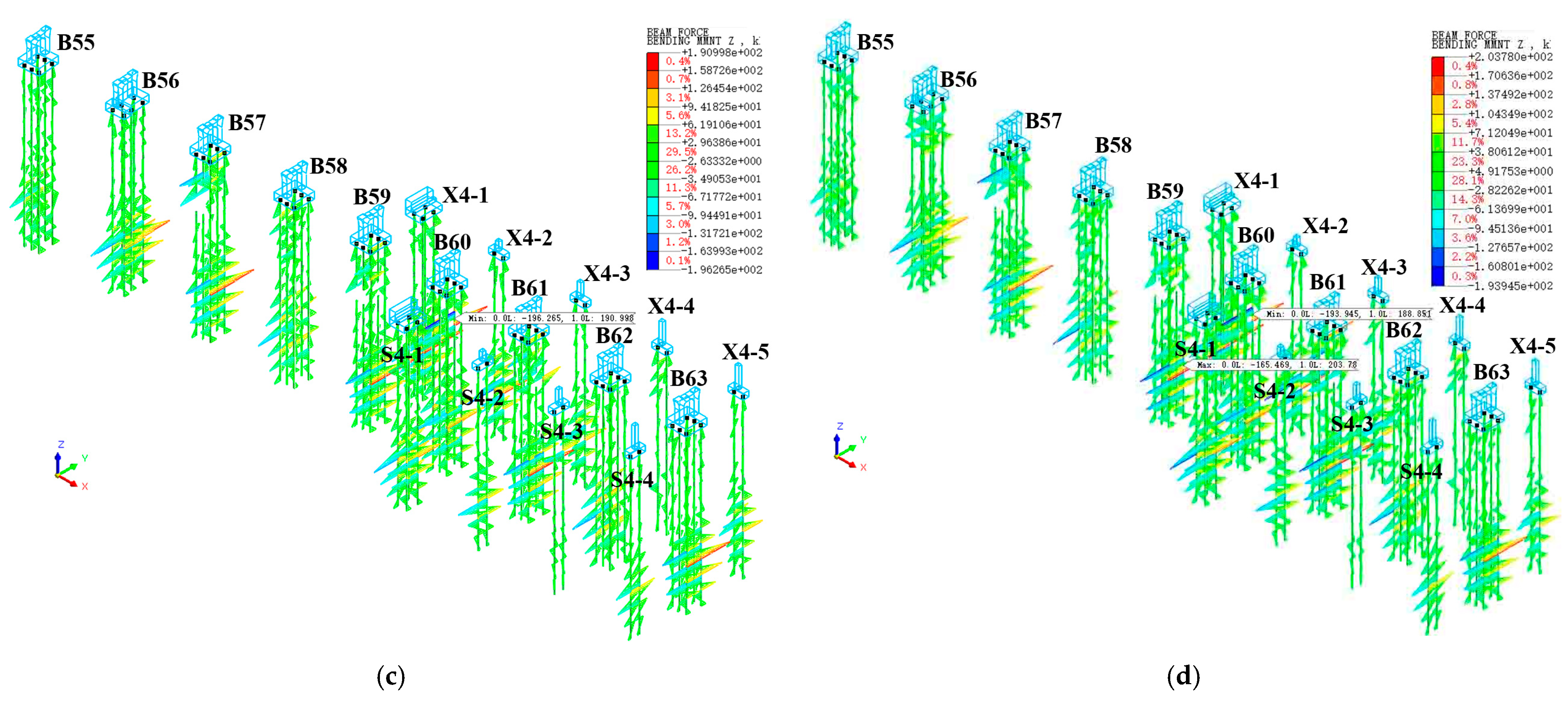
4.3.2. Internal Force Analysis of Bridge Foundation Structure

During the foundation pit excavation, the soil is disturbed, causing a redistribution of stress, which in turn changes the internal forces of the bridge structure. Figure 13 shows the axial force and bending moment diagrams of the structure before and after the excavation. It can be seen that the maximum axial force before excavation is 4153 kN, while after excavation it is 4184 kN, indicating that the excavation has a negligible impact on the axial force of the bridge structure (0.7%). This is because the excavation primarily alters the stress state of the soil around the foundation pit rather than directly affecting the axial direction of the bridge. An analysis of Figure 13c,d shows that the maximum positive bending moment before excavation is 191 kN·m, and the maximum bending moment after excavation is 203 kN·m, with a bending moment change rate of 6.3%. This increase in the bending moment is due to the settlement displacement of the foundation after excavation and the constraint of the bridge deck stiffness, which leads to an increase in the bending moment of the foundation structure. In summary, the excavation of the foundation pit has a significant impact on the bending moment of the bridge structure but does not have a noticeable effect on the axial force of the bridge structure.

5. Construction and Monitoring Onsite

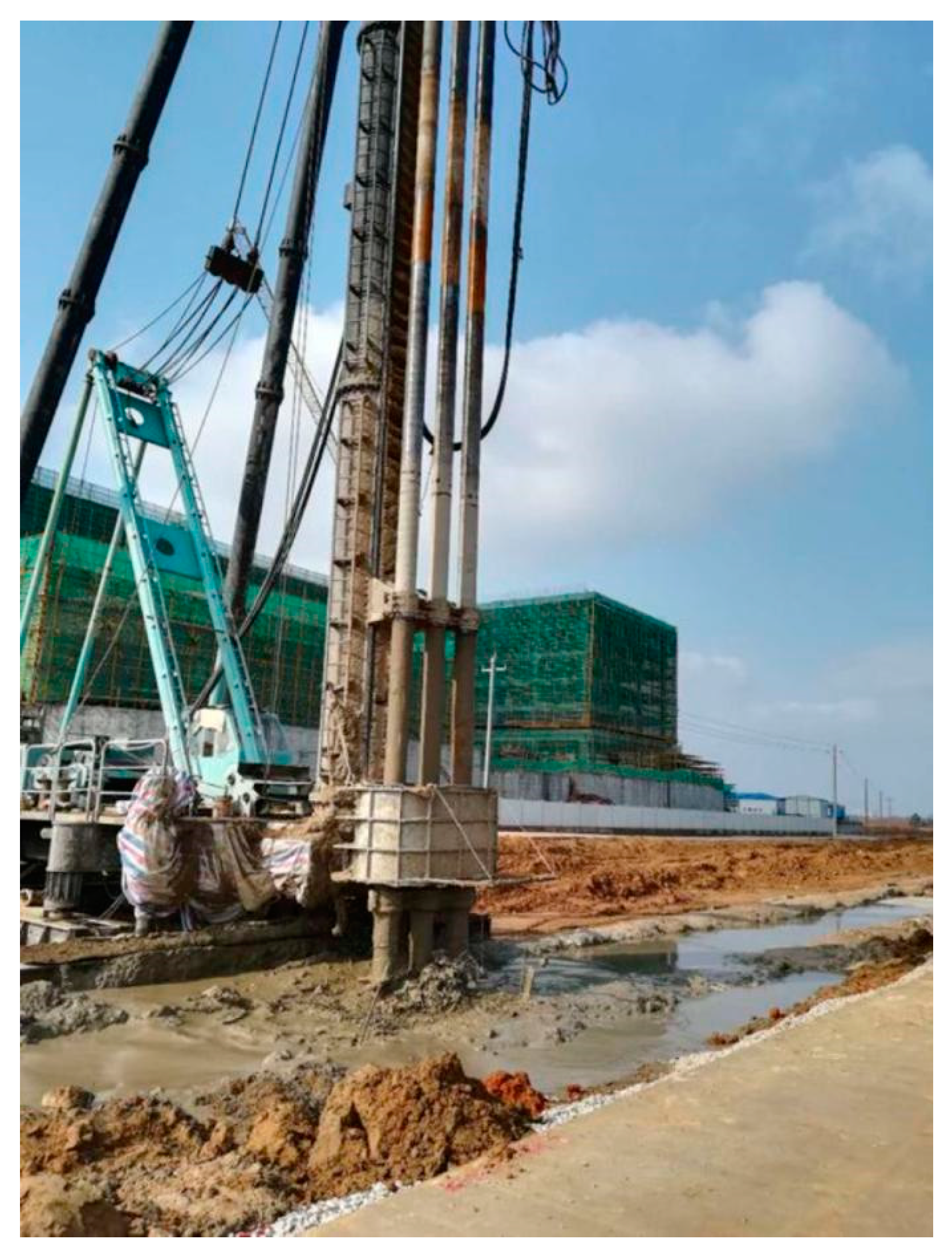
5.1. Construction Onsite

Deep cement mixing piles use cement as the main solidifying agent [38]. The construction of the piles is shown in Figure 14. Specialized deep mixing machinery is employed to forcibly mix soft soil with the solidifying agent in situ, causing the soft soil to harden and thereby increasing the foundation strength. This method is particularly effective for treating soft soil, yielding significant results and allowing for quick usage after treatment. Construction methods can be categorized based on the state of the reinforcement materials used: the slurry mixing method (wet method, as specified in these guidelines for deep cement slurry mixing) and the powder mixing method (dry method). The deep cement mixing piles utilize the PH-5 series deep mixing pile machine and corresponding auxiliary equipment, such as grout pumps and grout mixers, to prepare the cement slurry. An aerial photo of the site is shown in Figure 15.
The construction process for deep mixing piles is as follows:
(1)
Mark pile positions.
(2)
Position the drilling rig.
(3)
Inspect and adjust the drilling rig.
(4)
Perform forward circulation drilling to the design depth.
(5)
Activate the high-pressure grouting pump.
(6)
Perform reverse circulation while lifting the drill and injecting cement slurry until 0.3 m below the working reference surface.
(7)
Repeat the downward mixing while injecting cement slurry to the design depth.
(8)
Perform reverse circulation lifting to the ground surface.
(9)
Complete pile formation.
(10)
Proceed to the next pile.

5.2. Monitoring Onsite

Due to the heterogeneity, anisotropy, and discontinuity of the soil composition, as well as the uncontrollable influences of natural environmental factors, it is necessary to use monitoring methods for essential supplementation to obtain relevant information in a timely manner and ensure the stability and safety of the surrounding environment. Onsite monitoring allows for an understanding of the actual displacement and stress distribution of the surrounding soil, which can be used to verify the degree of conformity between design and reality. Additionally, it provides valuable guidance for construction based on the displacement and stress distribution conditions.
The foundation pit excavation project was completed in May 2023. Subsequently, monitoring began, which was divided into three stages:
(1)
Stage 1, June 2023;
(2)
Stage 2, November 2023;
(3)
Stage 3, May 2024.
The locations of the observation points are shown in Figure 16. A schematic diagram of the observation point layout on each pier can be seen in Figure 17.

5.3. Analysis and Discussion of the Settlement Values

Figure 18 indicates the measured results for each numbered monitoring point across the three observation stages. The green line represents the settlement curve after the completion of process 11 in the finite element simulation; although the measuring points are not exactly the same, they can still be used as a reference. Analyzing Figure 18a, it can be seen that during stage 1, the settlement of the bridge foundation is relatively large, with a pattern similar to the finite element simulation results, showing more settlement in the middle and less at the ends. In the subsequent stages 2 and 3, the curves become flatter, and the central settlement decreases. This is due to the stiffness rebound of the upper bridge deck after excavation, which reduces the load on the bridge foundation in the central area of the study region. Additionally, soil consolidation and stress redistribution contribute to the reduced central settlement, leading to a more uniform overall settlement of the bridge foundation within the calculation region. Analyzing Figure 18b,c, it is evident that the actual settlement of the ramp bridge further from the foundation pit is relatively smaller than that of the ramp bridge closer to the foundation pit. Additionally, the settlement pattern of the ramp bridge significantly differs from the finite element results, particularly at measurement points X4-1 and S4-4. This discrepancy is partly because the connection between the ramp and the main bridge or ground is weak in the actual construction, so the displacement of the main bridge does not affect the ramp, resulting in less constraint and a less pronounced central uplift displacement trend. Moreover, there is also a certain gap between the finite element simulation results and the measured results due to idealization in the theoretical simulations and errors during the measurements, which cannot fully replicate the complexities of the actual site conditions.

6. Conclusions

Based on a deep excavation project near an elevated bridge in Wuhan, a three-dimensional finite element model was used to simulate and analyze the impact of the excavation process on the adjacent elevated bridge. The conclusions are as follows:
(1)
According to the 3D numerical analysis results, the maximum displacements of the retaining structure and surface settlement were found to be 9.55 mm and 17.4 mm, respectively. The bridge experienced a maximum horizontal displacement of 2.98 mm and a vertical displacement of −1.75 mm during the excavation, with maximum settlement between piers B58 and B60. The maximum change rate of the bending moment in the bridge structure caused by the foundation pit construction is 6.3%, but there are almost no changes in the axial forces of the bridge structure. All of these values are within the acceptable displacement limits for bridge safety.
(2)
Displacement primarily occurred during excavation, stabilizing in the final procedure. The displacements in the middle of the main bridge structure are relatively larger and the displacement of the near-bridge ramp is greater than that of the far-bridge ramp. The near-bridge ramp exhibited greater horizontal displacement due to its connection to the main bridge while the vertical displacement was larger at both ends of the near-bridge ramp; both the main and ramp bridge display the reverse arch phenomenon due to stiffness constraints, resulting in greater absolute values of negative displacement in the middle and positive displacement at both ends.
(3)
A comparison of the observed settlement values with the finite element simulation indicated smoother observed curves that stabilize over time due to stress redistribution, soil consolidation, and bridge deck rigidity rebound. Uneven settlement may cause lateral displacement and inclination, with a maximum inclination of 0.6‰ observed at the one-third points of the bridge. The inclination and settlement of the ramp near the excavation pit are more pronounced.
In summary, although there may be errors in the observed values due to the limitations of the observation duration and accuracy, the overall results are relatively reliable. This further confirms that the impact of the excavation on the bridge is controllable and that the construction process and maintenance structures are reasonable.

Author Contributions

Conceptualization, J.H.; Methodology, J.Y. and X.Y.; Software, X.Y.; Formal analysis, K.G.; Investigation, J.Y.; Resources, J.H., J.Y. and K.G.; Data curation, S.P.; Writing—original draft, K.G. and X.Y.; Writing—review & editing, C.W.; Visualization, J.H., J.Y. and S.P.; Supervision, J.H.; Project administration, J.H.; Funding acquisition, C.W. All authors have read and agreed to the published version of the manuscript.

Funding

The authors acknowledge the financial support from the Natural Science Foundation Youth Project of Hubei Province (JCZRQN202400959).

Data Availability Statement

Data will be made available on reasonable request.

Conflicts of Interest

Author Jun Yan was employed by the company Wuhan Bohong Construction Group Co., Ltd. Authors Kai Guo and Xingyue Yang were employed by the company Wuhan Municipal Engineering Design & Research Institute Co., Ltd. The remaining authors declare that the research was conducted in the absence of any commercial or financial relationships that could be construed as a potential conflict of interest.

References

  1. Guo, C.; Jin, X.; Yang, X.; Xu, W.; Sun, R.; Zhou, Y. Comprehensive evaluation of newly cultivated land sustainable utilization at project scale: A case study in Guangdong, China. J. Geogr. Sci. 2024, 34, 745–762. [Google Scholar] [CrossRef]
  2. Sommer, D.; Plieninger, S. Three pedestrian bridges for China. Bautechnik 2023, 100, 135–142. [Google Scholar] [CrossRef]
  3. Chen, Y.; Wang, X.; Sun, C.; Zhu, B. Exploring the failure mechanism of light poles on elevated bridges under high winds. Eng. Fail. Anal. 2024, 159, 108076. [Google Scholar] [CrossRef]
  4. Xia, H.; Guo, W.W.; Xia, C.Y.; Pi, Y.L.; Bradford, M.A. Dynamic interaction analysis of a LIM train and elevated bridge system. J. Mech. Sci. Technol. 2009, 23, 3257–3270. [Google Scholar] [CrossRef]
  5. Ming, C.; Wei, W.; Haibo, W. Field Tests and Simulation of Ground and Building Vibrations Caused by Metros on an Elevated Bridge. IEEE Access 2018, 6, 627–636. [Google Scholar] [CrossRef]
  6. Yu, C.; Long, J.; Lu, M. Study on the influence of deep foundation pit excavation on adjacent metro structure. IOP Conf. Ser. Earth Environ. Sci. 2021, 768, 012101. [Google Scholar] [CrossRef]
  7. Huang, J.; Liu, J.; Guo, K.; Wu, C.; Yang, S.; Luo, M.; Lu, Y. Numerical Simulation Study on the Impact of Deep Foundation Pit Excavation on Adjacent Rail Transit Structures—A Case Study. Buildings 2024, 14, 1853. [Google Scholar] [CrossRef]
  8. Pei, Q.; Wang, X.; He, L.; Liu, L.; Tian, Y.; Wu, C. Estimation Method for an In Situ Stress Field along a Super-Long and Deep-Buried Tunnel and Its Application. Buildings 2023, 13, 1924. [Google Scholar] [CrossRef]
  9. Poulos, H.G. From theory to practice in pile design. Int. J. Rock Mech. Min. Sci. Geomech. Abstr. 1998, 26, 85–86. [Google Scholar] [CrossRef]
  10. Reese, L.; Van Impe, W.F. Single piles and pile groups under lateral loading. Appl. Mech. Rev. 2002, 55, B9–B10. [Google Scholar] [CrossRef]
  11. Basack, S.; Nimbalkar, S.; Zaman, M. Recent developments in pile foundations: Design, construction, innovations and case studies. Int. J. Geotech. Eng. 2023, 17, 581–582. [Google Scholar] [CrossRef]
  12. Li, Z.; Zhao, G.-F.; Deng, X.; Zhu, J.; Zhang, Q. Further development of distinct lattice spring model for stability and collapse analysis of deep foundation pit excavation. Comput. Geotech. 2022, 14, 104619. [Google Scholar] [CrossRef]
  13. Chin, Y.-T.; Shen, S.-L.; Zhou, A.-N.; Chen, J. Foundation Pit Collapse on 8 June 2019 in Nanning, China: A Brief Report. Safety 2019, 5, 68. [Google Scholar] [CrossRef]
  14. Si, W.J.; Wang, Y.J.; Gao, Y.F.; Zhou, H. Safety Assessment on Retaining and Protecting of Deep Foundation Excavation Adjacent to the Existing Railway. Appl. Mech. Mater. 2013, 363, 1511–1514. [Google Scholar] [CrossRef]
  15. Ding, J.S.; Xian, Y.Q.; Liu, T.J. Numerical Modeling of Affection of Foundation Pit Excavation on Metro Tunnel. Adv. Mater. Res. 2012, 368–373, 2562–2566. [Google Scholar] [CrossRef]
  16. Shi, C.; Peng, L. Ground surface settlement caused by foundation pit excavation and dewatering. China Civ. Eng. J. 2006, 39, 117–121. [Google Scholar] [CrossRef]
  17. Zhang, J.; Xie, R.; Zhang, H. Mechanical response analysis of the buried pipeline due to adjacent foundation pit excavation. Tunn. Undergr. Space Technol. 2018, 78, 135–145. [Google Scholar] [CrossRef]
  18. Xu, C.J.; Yin, M.; Lin, G. Characters Analysis of the Retaining Structure of the Foundation Pit under Local Load. Appl. Mech. Mater. 2014, 477–478, 448–452. [Google Scholar] [CrossRef]
  19. Jun, C.L.; Zhuo, Y.Z.; Guo, Y.L. Study on effects of time-space of retaining structures of the deep-foundation pit excavation. Rock Soil Mech. 2003, 24, 812–816. [Google Scholar] [CrossRef]
  20. Wang, R.S.; Guo, C.C.; Lin, P.Y.; Wang, F.M. Excavation response analysis of prefabricated recyclable support structure for water-rich silt foundation pit. Rock Soil Mech. 2023, 44, 843–853. [Google Scholar] [CrossRef]
  21. Xia, H.; Deng, Y.; Zou, Y.; De Roeck, G.; Degrande, G. Dynamic analysis of rail transit elevated bridge with ladder track. Front. Archit. Civ. Eng. China 2009, 3, 2–8. [Google Scholar] [CrossRef]
  22. Tamotsu, M.; Kazuhiro, O. Foundation damage of structures. Soils Found. 2012, 36, 189–200. [Google Scholar] [CrossRef]
  23. Wang, Z.C.; Guo, X.P.; Wang, C. Field monitoring analysis of construction process of deep foundation pit at subway station. Ge-Otech. Geol. Eng. 2019, 37, 549–559. [Google Scholar] [CrossRef]
  24. Bing, H.L.; Xing, W.L.; Zu, Y.S. Comparison of the Application Effects of Two Supporting Forms in a Deep Foundation Pit Engineering. In Proceedings of the International Symposium on Architectural Interchanges in Asia, Hangzhou, China, 14–17 October 2014. [Google Scholar]
  25. Pearlman, S.L.; Walker, M.P.; Boscardin, M.D. Deep Underground Basements for Major Urban Building Construction. In Proceedings of the GeoSupport 2004: Innovation and Cooperation in the Geo-Industry, Orlando, FL, USA, 29–31 January 2004; pp. 545–560. [Google Scholar] [CrossRef]
  26. Klotz, U.; Vermeer, P.A.; Klotz, C.; Möller, S. A 3D finite element simulation of a shield tunnel in weathered Singapore Bukit Timah Granite. Tunn. Undergr. Space Technol. 2006, 21, 272. [Google Scholar] [CrossRef]
  27. Suh, J.M.W. Multi-agent based traffic simulation and integrated control of freeway corridors: Part 1 simulation and control model. J. Mech. Sci. Technol. 2009, 23, 1365–1373. [Google Scholar] [CrossRef]
  28. Chen, B.G.; Jia, Z.P. Optimal strut position of deep foundation pit with convex corner under surcharge of adjacent building. Rock Soil Mech. 2023, 44, 2400–2408. [Google Scholar] [CrossRef]
  29. Liu, J.; Xue, B.; Wang, H.; Zhang, X.; Zhang, Y. Numerical study on the behavior of an existing tunnel during excavating adjacent deep foundation pit. Sustainability 2023, 15, 9740. [Google Scholar] [CrossRef]
  30. Matsumoto, T.; Kitiyodom, P.; Matsui, H.; Katsuzaki, Y. Monitoring of load distribution of the piles of a bridge during and after construction. J. Jpn. Geotech. Soc. 2004, 44, 109–117. [Google Scholar] [CrossRef]
  31. Ayasrah, M.; Qiu, S.H.; Zhang, X. Influence of Cairo Metro Tunnel Excavation on Pile Deep Foundation of the Adjacent Under-ground Structures: Numerical Study. Symetry 2021, 13, 426. [Google Scholar] [CrossRef]
  32. Ning, W.; Ming, H. Deformation Monitoring Artificial Neural Network Model of Deep Foundation Pit Considering the Excavation Effect. J. Shanghai Jiaotong Univ. 2009, 43, 990–993. [Google Scholar] [CrossRef]
  33. Ding, Z.; Jin, J.; Han, T.-C. Analysis of the zoning excavation monitoring data of a narrow and deep foundation pit in a soft soil area. J. Geophys. Eng. 2018, 15, 1231. [Google Scholar] [CrossRef]
  34. Lowry, K.; Rayhani, M.T. Factors Affecting Axial and Lateral Load Transfer of Hollow Fibre-Reinforced Polymer Piles in Soft Clay. Int. J. Geotech. Eng. 2024, 17, 644–653. [Google Scholar] [CrossRef]
  35. GB50010-2010; Code for Design of Concrete Structures. Ministry of Housing and Urban Rural Development of the People’s Republic of China: Beijing, China, 2015.
  36. Ahmad, M.; Ray, R. Modelling of the Torsional Simple Shear Test with Randomized Tresca Model Properties in Midas GTS NX. Geotech. Geol. Eng. 2023, 41, 1937–1946. [Google Scholar] [CrossRef]
  37. DB 42/T159-2012; Technical Specifications for Foundation Pit Engineering. Hubei Provincial Department of Housing and Urban Rural Development: Wuhan, China, 2012.
  38. JGJ79-2012; Technical Code for Ground Treatment of Buildings. Ministry of Housing and Urban Rural Development of the People’s Republic of China: Beijing, China, 2015.
Figure 1. Schematic diagram of the construction site before the excavation.
Buildings 14 02541 g001
Figure 2. Plan view of the relationship between the excavation pit and the bridge.
Buildings 14 02541 g002
Figure 3. Vertical relationship between the foundation pit and the bridge.
Buildings 14 02541 g003
Figure 4. Axial view of the calculation model.
Buildings 14 02541 g004
Figure 5. Model of retaining structure and bridge pier.
Buildings 14 02541 g005
Figure 6. Overall displacement of the model after construction: (a) vertical; (b) horizontal.
Buildings 14 02541 g006
Figure 7. Horizontal displacement of foundation pit support structures after (a) excavation procedure 7; (b) excavation procedure 9; (c) procedure 10; (d) procedure 11.
Buildings 14 02541 g007aBuildings 14 02541 g007b
Figure 8. Horizontal displacements of the pile foundation after (a) excavation procedure 7; (b) excavation procedure 9; (c) procedure 10; (d) procedure 11.
Buildings 14 02541 g008
Figure 9. Horizontal displacement of the bridge: (a) main bridge; (b) ramp bridge far from the foundation pit; (c) ramp bridge close to the foundation pit.
Buildings 14 02541 g009
Figure 10. Vwetical displacements of the pile foundation after (a) excavation procedure 7; (b) excavation procedure 9; (c) procedure 10; (d) procedure 11.
Buildings 14 02541 g010
Figure 11. Vertical displacement of the bridge: (a) main bridge; (b) ramp bridge far from the foundation pit; (c) ramp bridge close to the foundation pit.
Buildings 14 02541 g011
Figure 12. Displacement of the bridge deck after procedure 11: (a) horizontal; (b) vertical.
Buildings 14 02541 g012
Figure 13. Cloud plot of internal forces in the foundation structure of the bridge: (a) axial force before excavation; (b) axial force after excavation; (c) bending moment before excavation; (d) bending moment after excavation.
Buildings 14 02541 g013aBuildings 14 02541 g013b
Figure 14. Construction of the deep cement mixing piles utilized.
Buildings 14 02541 g014
Figure 15. Aerial photo of the site during construction: (a) procedure 7; (b) procedure 11.
Buildings 14 02541 g015
Figure 16. Locations of the measured points on the bridge.
Buildings 14 02541 g016
Figure 17. Layout of the monitoring points of piles in main bridge.
Buildings 14 02541 g017
Figure 18. Measured settlements and the comparisons: (a) main bridge; (b) ramp bridge far from the foundation bridge; (c) ramp bridge close to the foundation pit.
Buildings 14 02541 g018
Table 1. Main physical and mechanical parameters of the model’s geotechnical layers.
Soil Layer NameConstitutive ModelUnit Weight (kN/m3)c (kPa)Φ
(°)
Eoedref
(MPa)
E50ref
(MPa)
Eurref
(MPa)
Poisson’s Ratio
1 Miscellaneous fillModified Mohr–Coulomb18.081755150.4
2 Silty clay Modified Mohr–Coulomb18.0181155150.35
3-1 Silty clay with siltModified Mohr–Coulomb16.91253390.45
3-2 Silty clay with silt and fine sandModified Mohr–Coulomb17.917955150.3
4-1 Fine sand with silty clayModified Mohr–Coulomb18.42258.58.525.50.3
4-2 Fine silty sandModified Mohr–Coulomb18.502815.415.446.20.3
6-1 Strongly weathered mudstoneModified Mohr–Coulomb19 *20 *25 *2020600.28
6-2 Moderately weathered mudstoneModified Mohr–Coulomb20 *50 *35 *50501000.25
The values marked with * are provided by authoritative geological survey organization based on experiences.
Table 2. Structural mechanical parameters.
Structural NameTypeSection Size (mm)Unit Weight (kN/m3)E (Gpa)Poisson’s Ratio
Row pilePlate6672532.50.2
Capping beamBeam1100 × 8002530.00.2
Internal supportBeam800 × 8002530.00.2
Column pileBeamDiameter of 9002530.00.2
ColumnBeam4L160 × 1678.5206.00.2
Bridge pileBeamDiameter of 12002528.00.2
Pile capSolidStructural size2528.00.2
Bridge pierSolidStructural size2528.00.2
Bridge bodyPlateStructural size2528.00.2
Table 3. Simulated construction procedures.
ProceduresConditionDescription
1Initial flow fieldActivate all strata and initial water head
2Initial stressActivate stress boundaries and loads
3Bridge constructionConstruct bridge structure
4Displacement reset——
5Pile and column constructionConstruct piles and columns for foundation pit, apply additional load
6Dewatering 1Foundation pit dewatering
7Excavation 1Excavate foundation pit to the bottom of the first support
8Installation of concrete supportsActive concrete supports
9Excavation 2 Excavate foundation pit to the bottom and construct bottom slab
10Main structure constructionSimulate the analysis of bracing replacement
11Remove supportsRemove internal supports and construct roof slab
Disclaimer/Publisher’s Note: The statements, opinions and data contained in all publications are solely those of the individual author(s) and contributor(s) and not of MDPI and/or the editor(s). MDPI and/or the editor(s) disclaim responsibility for any injury to people or property resulting from any ideas, methods, instructions or products referred to in the content.

