Article

Analytical Formulation and Optimization of the Initial Morphology of Double-Layer Cable Truss Flexible Photovoltaic Supports

1
Key Laboratory of Concrete and Prestressed Concrete Structures of Ministry of Education, Southeast University, Nanjing 211189, China
2
National Prestressed Engineering Research Center, Southeast University, Nanjing 211189, China
3
Nanjing Dong-Da Modern Prestressed Engineering Co., Ltd., Nanjing 210018, China
*
Authors to whom correspondence should be addressed.
Buildings 2024, 14(8), 2549; https://doi.org/10.3390/buildings14082549
Submission received: 26 July 2024 / Revised: 13 August 2024 / Accepted: 16 August 2024 / Published: 19 August 2024
(This article belongs to the Special Issue Advancements in Large-Span Steel Structures and Architectural Design)

Abstract

:
With the rapid development of the photovoltaic industry, flexible photovoltaic supports are increasingly widely used. Parameters such as the deflection, span, and cross-sectional dimensions of cables are important factors affecting their mechanical and economic performance. Therefore, in order to reduce steel consumption and cost and improve application value, it is crucial to design and optimize their initial morphology. In this paper, the mechanical behavior of a single-cable structure is introduced, and the simplified analytical formulations for internal force and displacement are deduced based on the geometric nonlinear characteristics and small strain assumption of the flexible photovoltaic supports. On this basis, the analytical expressions for the cable force and displacement of a convex prestressed double-layer cable truss flexible photovoltaic support structure under a uniform load are derived, and the correctness of the analytical formulations is verified by comparing the values with the finite element analysis results. In order to reduce the construction costs of the flexible photovoltaic support, a mathematical model for optimizing the initial structure’s morphology is established according to the analytical formulations. The initial morphology of the double-layer cable truss flexible photovoltaic support is optimized, and the optimization results of different deflection deformation limits and whether the lower load-bearing cable is allowed to relax are compared. The results indicate that the errors of the displacement formulation and cable force formulation, when compared with the finite element results, are less than 3% and 4%, respectively, which verifies the accuracy of the analytical formulations. By analyzing the cable force and displacement of the structure under static action, it is suggested that the deflection limit of the double-layer cable truss structure should be 1/100 of the single span. The lower load-bearing cables of the double-layer cable truss flexible photovoltaic support are highly susceptible to relaxation under wind suction loads, and, by comparing the optimization results, it is suggested that slack should be allowed in the lower load-bearing cables for a better economic effect. When choosing the most economical structure morphology, it is recommended that the total height of the mid-span struts should be 1/20~1/15 of the single span. The analytical formulation and the mathematical model for the optimization of the initial morphology proposed in this paper can provide certain theoretical references and bases for the design of practical engineering projects and play an important role in promoting its application and promotion.

1. Introduction

Photovoltaic power generation has become an important source for the promotion of low-carbon energy transition, with the rapid development of the global photovoltaic industry. However, land plains with an excellent geology have been rapidly depleted. In order to ensure the sustainable development of this industry, the use of low-quality land such as mountain steep slopes, sewage treatment plants, ponds, beaches, and the land in the Gobi Desert has become inevitable. The traditional rigid photovoltaic supports shown in Figure 1a are not suitable for a land type, with poor geological conditions brought by the high flatness requirements of the site, the low utilization rate of the site’s space, the uneven foundations, the large amount of steel required, and poor economic returns. In recent years, a flexible photovoltaic support, which uses prestressed cables to fix and support the photovoltaic module and which transmits the upper load to the foundation through a substructure on both sides of the cable, has gradually received extensive attention in the engineering field. An example of this is shown in Figure 1b. Compared to the traditional fixed photovoltaic support, the flexible photovoltaic support shows unparalleled superiority in large sites such as steep slopes in mountainous areas, barren slopes in the Gobi Desert, and ponds; this is due to the ability of this structure to attain a flexible layout over large areas, as well as requiring a low level of steel consumption and having good site adaptability. In addition, the characteristics of the secondary utilization of the space below the structure are in line with the efficient energy utilization strategies represented by fishery–photovoltaic complementarity and agriculture–photovoltaic complementarity, conducive to the application of flexible photovoltaic supports.
The flexible photovoltaic support structure consists of two parts: the flexible cable system and the lower support system. The flexible cable system is composed of a load-bearing cable, a stability cable, a wind-resistant cable, a ground anchor towing structure, a strut-connecting load-bearing cable with a stability cable, a photovoltaic module, and a module clamp. The lower support system is composed of a foundation, a steel column, a crossbeam, column bracing, and a diagonal-bracing or stay cable. Depending on the structure of their prestressed cables, flexible photovoltaic supports can be categorized into the single-layer suspension cable type and the double-layer cable truss type. The cable truss flexible photovoltaic support (CTFPS) is mainly composed of load-bearing cables, stability cables, and struts, with a higher overall stiffness which significantly reduces the deformation of the structure under the wind load compared to single-layer suspension cable structures.
The research on photovoltaic supports mainly focuses on two aspects: one is static performance and the other is wind vibration response analysis. In terms of static performance research, Jiang et al. [1] derived the law of cable force increment and cable displacement due to a change in suspension in an equilibrium state under a uniform load based on the energy principle. Ding et al. [2] conducted a detailed study on the failure mode and bearing capacity of the new cable-supported photovoltaic system; they proposed a design method based on a limit state. The results showed that the structure has a strong bearing capacity; cable failure and triangular bracket failure are the two main modes of primary structure failure, and the sectional area of the cable is the most critical factor in terms of affecting the bearing capacity. Desai et al. [3] proposed a stiffness matrix of a three-node parabolic cable element to analyze the geometric nonlinearity of cable-supported structures; this stiffness matrix can effectively describe the deformation characteristics of cable-supported structures. Bartholet et al. [4] developed a cable-supported photovoltaic structure that tracks sunlight and demonstrated its construction feasibility. Li et al. [5] conducted a fluctuating-wind dynamic time–history analysis and an equivalent static analysis on structures based on different design parameters in order to study the force and deformation of single-layer cable-suspended flexible photovoltaic support structures. The analysis results showed that the initial prestress of cables could significantly increase the structural stiffness and change the structural dynamic characteristics of the structures, and the span was the main factor affecting the structural deformation and gust factor. Zhang et al. [6] calculated the cable force and displacement of the flexible photovoltaic supports under wind pressure and wind suction load and analyzed the influence of the initial tension and vector height of the cable on the cable force and displacement. The results showed that the load-bearing cables would relax under wind suction load, and the load was mainly born by the stability cables; meanwhile, the load was born jointly by the stability cables and the load-bearing cables under wind pressure load. However, the influence of the initial tension of the load-bearing cables on the displacement of the cable truss was more obvious, and the vector height of the stability cables could effectively reduce the displacement under wind suction load. Du et al. [7] proposed three new flexible photovoltaic supports, studied the methods of load and deformation limit of the three flexible photovoltaic supports, and analyzed the vertical deflection, cable force, and sectional stress. The results indicated that the deflection limit values of the main and secondary cable of photovoltaic supports with flexible suspension cable structures were L/150 and L/50, respectively. Yuan et al. [8] used ABAQUS16.0 to conduct an analysis of static performance, dynamic characteristics, dynamic response, and gust factor of the double-layer cable-suspended flexible photovoltaic supports structure, and investigated the influence of the span, the spacing of transverse connecting system, and deflection limit on structural performance. The results showed that the wind vibration response of the structure increased with the increase in the span and the mid-span deflection; the upper cable force increased with the increase in the transverse connection distance; the increase in the upper cable prestress could reduce the dynamic response of the structure; meanwhile, the increase in the lower cable prestress lead to the increase in the wind vibration response of the structure. He et al. [9] established a finite element model of a double-layer cable truss photovoltaic support, and a conducted modal analysis and a static characteristics study on the inverted arch model; they concluded that the torsional stiffness and bearing capacity of this structure were significantly improved compared with a single-layer flexible photovoltaic support. Furthermore, the influences of support arrangement spacing, photovoltaic module inclination angle, initial tension, and cable diameter on the structural characteristics were further studied. Shen et al. [10] designed a fixed and adjustable photovoltaic support based on the actual photovoltaic substation project, proposed an innovative optimization design by comparing the advantages and disadvantages with existing supports, and analyzed the mechanical behavior of the support to test the rationality. Kilikevicius et al. [11] studied the dynamic load of photovoltaic modules on both the theoretical and experimental aspects, and designed a dynamic load test bench to apply cyclic dynamic load excitation to photovoltaic modules. The tests used excitation of no more than 7 mm amplitude and frequencies ranging from 0 to 40 Hz, and frequency-sweep power generation is used to simulate different weather conditions. The experimental and theoretical responses of photovoltaic modules under different weather conditions show that the evaluation method can be successfully applied to the design and mechanical response analysis of photovoltaic modules. Bao et al. [12] obtained the dynamic characteristics of the tracking photovoltaic support system under different inclination angles through field modal tests, and found that three torsional modes in the frequency range of 2.9–5.0 Hz, accompanied by a small damping rate ranging from 1.07 to 2.99%; they proposed a finite element analysis method for the tracking photovoltaic support system, which obtained four torsional modes in a frequency range of 2.8–7.0 Hz. Tang et al. [13] conducted simulation calculations for different forms of flexible photovoltaic support to compare the mechanical characteristics of three horizontal load-bearing components, and studied the influence of changes in the inclination angle θ between horizontal load-bearing components and the ground on structural mechanical behavior.
In terms of wind vibration response analysis, Chen et al. [14] provided a comprehensive review of the latest research on the aerodynamic characteristics and wind responses of flexible photovoltaic systems. They used physical and numerical simulation tools to compare the effects of parameters such as spacing ratio, wind attack angle, tilt, and position, and recorded the dynamic responses including buffeting-, flutter-, and vortex-induced vibration. Xu et al. [15] conducted aeroelastic wind tunnel tests and rigid model wind tunnel tests on a flexible photovoltaic system; the characteristics of wind vibration were studied, and the influence of several factors on displacement response and aerodynamic damping were analyzed. Liu et al. [16] investigated the wind vibration response and critical wind speed of a 33 m span flexible support structure based on the wind tunnel test of an elastic model, and examined the effect of three stability cables on improving the critical wind speed of the flexible support structure. Li et al. [17] conducted wind tests on cable-supported photovoltaic structures, studied the wind load response of photovoltaic arrays with different lengths and widths, and proposed wind load reduction factors for different array areas considering the wind shielding effect of upstream modules. Moreover, the gust load factor of photovoltaic arrays was obtained through numerical simulation and equivalent static analysis of wind-induced vibration. Abiola-Ogedengbe et al. [18] and Jubayer et al. [19] investigated the wind pressure distribution of a single photovoltaic module through wind tunnel tests and numerical simulations, respectively. They found that wind direction angle and photovoltaic module inclination angle are the main factors affecting surface wind load and determined the wind direction angle of a photovoltaic module subjected to the maximum lift and the maximum overturning moment. Davenport et al. [20] took the lead in introducing the a theory of random vibration, established the theoretical framework for structure vibration response analysis, and simplified a complex dynamic analysis into a static analysis by using the concept of gust load factor (GLF), thus pioneering the theoretical study of equivalent static wind load. Tamura et al. [21] and Kim et al. [22] investigated the vibration characteristics of single-layer flexible photovoltaic systems through wind tunnel tests; the results indicated that the structural displacement response of wind-induced vibration was closely related to the cable sag-to-span ratio, wind speed, and wind direction angle. In addition, the research demonstrated that fluctuating displacement is proportional to the square of the mean wind speed; this holds for all wind direction angles in boundary layer flow. Tan et al. [23] established a model of a row of three-span single-layer prestressed cables photovoltaic support, investigated the wind vibration response of the cable support by performing time–history analysis on the support subjected to fluctuating wind loads, and compared them with the displacements under static loads. The results indicated that the single-layer suspension cable support has larger vertical displacement and cable force under fluctuating wind load.
Scholars at home and abroad have also performed extensive research on the design optimization of photovoltaic supports and cable truss structures. Finotto et al. [24] proposed a “Hybrid Fuzzy Genetic System Algorithm” and compared the results of this optimization with those of a genetic algorithm. The results showed that the hybrid genetic optimization system greatly reduces iterations of the genetic algorithm and showed an advantage in minimizing the structural self-weight. Ma et al. [25] investigated the minimum mass design problem of a cable truss structure subjected to concentrated vertical loads in a given span by considering both loading and unloading conditions, proposed a new topology and configuration of the cable truss, and parameterized it with several variables. They optimized the topology and structure of the cable truss by using constrained nonlinear optimization of structural parameters and added the roof and nodes mass as penalty terms to the total mass. The efficiency and accuracy of the method were verified by numerical examples. Barbon et al. [26] proposed a method to estimate the optimal distribution of photovoltaic modules on a fixed inclination angle using the open-source QGIS, which took the variations in the local cloud cover distribution into account, and the optimization process was conducted by calculating the shadows between the photovoltaic modules using a filling algorithm. In the research, different support configurations and inclination angles were considered to adapt to the irregular shape of the land, and wind loads, snow loads, structural weights, photovoltaic module weights, and their combinations were calculated. Li et al. [27] proposed a topology optimization method for a prestressed cable truss structure that considers geometric nonlinearities and large deformation kinematics theory, which fully considered the geometric nonlinearities caused by external loads and prestresses. In order to consider the effect of prestress on the overall stiffness of the structure, the prestress was rebalanced, the objective function of the prestress corrected flexibility was constructed, the cable truss structure was equated to a specific two-phase material structure, and the material interpolation was realized by the baseline discrete material optimization class method. The sensitivity analysis of the accompanying objective function was carried out and the optimization problem was solved by a gradient-based algorithm. Lou et al. [28] developed a MATLAB code to simulate fluctuating wind load time history and performed structural modeling to evaluate safety performance under extreme wind conditions, exploring critical wind speeds associated with different spans and prestress within the system. The results showed that the mid-span displacements and axial forces of wind-resistant cables were greater under wind pressure conditions than under wind suction conditions; the wind-induced vibration coefficients suggested ranged from 1.5 to 2.52; the introduction of support beams in the mid-span was the most effective measure to mitigate wind-induced vibration responses; the installation of stability cables at the midspan significantly reduced the wind-induced vibration responses under wind suction loads. Wang et al. [29] described the design calculation method and process of the fixed photovoltaic supports by using SAP2000v18. Li et al. [30] proposed an equivalent equilibrium force model, EEFM, for cable truss structures, where the cable truss structure was divided into upper and lower cables with equivalent nodal forces, and the geometrical reasonableness could be easily assessed from the equivalent nodal force relationship; the self-stressing mode with reasonable geometry was obtained based on the geometrical topology of the two cables and the equilibrium equations. For geometrically irrational structures, the nodal coordinates of one cable were corrected according to the nodal coordinates of the other cable. The accuracy and effectiveness of the method were verified by several examples, and the method could be used in shape design, geometry correction, and force finding. Barbon et al. [31] proposed an optimization method that considered the most important design variables for uniaxial photovoltaic supports including irregular land shape, size, and configuration of the support, spacing, and duty cycle, and developed equations for determining the optimal spacing and duty cycle. They also proposed a filling algorithm that took irregular terrain and possible configurations of the installed system into account. The results showed that the proposed method optimized photovoltaic plants with uniaxial solar supports and provided reliable results in reasonable computation time. Chen et al. [32] derived analytical formulations for the deformation and cable forces of cable truss pedestrian bridge under full-span live load and half-span live load, and verified their reliability and accuracy by comparing with finite element analysis. Through parametric studies, the cable truss bridge was found to have several novel structural features different from those of traditional suspension bridges, and the bearing range of the cable truss bridge was discussed through material usage analysis. In summary, existing studies are mainly based on the influence of structural parameter changes on the structural performance in the design and optimization of cable trusses, with little attention to the economic performance of the structure and lack of discussion on the economy, and most of the parametric analyses are based on the comparison of finite element analysis, which is lack of the support of corresponding theoretical formulations.
The flexible photovoltaic support structure has no stiffness and an indeterminate shape before prestressing, and it must be provided with a certain shape by prestressing for withstanding the external loads. Under the given boundary conditions, the distribution and magnitude of prestressing are interrelated with the initial morphology of structure. Therefore, the initial geometric position and initial prestresses of the load-bearing cable and stability cable are crucial for the design of the flexible photovoltaic support structure. For the flexible photovoltaic support structure, the evaluation criteria of structural performance should be established according to its working characteristics, and its “shape” and “state” under prestress and load should be analyzed and compared, so as to obtain the optimal initial state under the premise of economy and functional requirements. Finally, the results of the morphological optimization of the flexible photovoltaic support structure are verified to ensure the accuracy and satisfaction of parameter optimization.
In summary, the research on flexible photovoltaic support structures is still in infancy and mainly focuses on the above two aspects, and there are still substantial problems to be researched. One of them is to optimize the initial morphology under the premise of economy and requirements as much as possible for the reduction in steel consumption and cost. In the initial state, the rise-to-span ratio of stability cable and the sag-to-span ratio of the load-bearing cable are significant geometric parameters affecting the performance of convex prestressed cable truss structures. For flexible photovoltaic supports, previous studies are mainly based on the dynamic analysis of existing morphology, including wind vibration response analysis, wind load analysis and wind tunnel tests, etc., but little attention has been paid to the initial structural design and optimization of flexible photovoltaic supports, which is not only related to the static mechanical behavior and cost, but also related to the dynamic response of the structure. Therefore, the initial structure design and optimization is the basis of dynamic response analysis, and it is necessary to study some key problems in the initial structure design of flexible photovoltaic supports. Although domestic and foreign scholars have conducted in-depth studies on the morphology and performance of cable trusses based on the single-cable theory, these studies are mostly based on classical theories, whose expressions are very cumbersome and difficult to directly apply to the conceptual design of the structure at the initial stage, and relevant specifications such as China’s “Cable structure Technical Regulations” (JGJ257-2012) [33] have not given clear provisions on the tension sag-to-span ratio of flexible photovoltaic supports. In order to resolve this problem, this paper analyzes the morphology and performance of convex prestressed CTFPS structures under uniform load along the span direction based on the single-cable theory, refines concise analytical formulations, provides suggested values of the flexural deformation limit, the deflection-to-span ratio, and the sag-to-span ratio; this provides a design basis for the conceptual design of flexible photovoltaic support structure, and a mathematical optimization model was established based on the analytical formulations, which can be used to optimize the initial morphology in the structural design stage. The analytical formulation and the mathematical model for the optimization of the initial morphology proposed in this paper can provide certain theoretical references and bases for the design of practical engineering projects and play an important role in promoting its application and promotion.

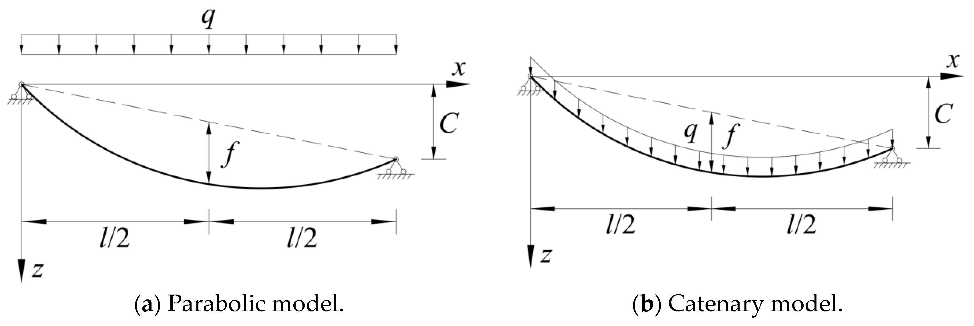
2. The Relationship between the Force and the Geometric Morphology of the Single-Cable Structure

2.1. Basic Assumption

The basic component of a cable-suspended structure is a single cable, and the following assumptions are introduced when the mechanical behavior of a single cable is deduced according to the relationship between the morphology and the force:
(1)
The cable is ideally flexible, and can only be tensioned, not compressed or bent.
(2)
The material properties of cables conform to Hooke’s law without considering plastic deformation.
(3)
The strain of cables under the upper load is small.

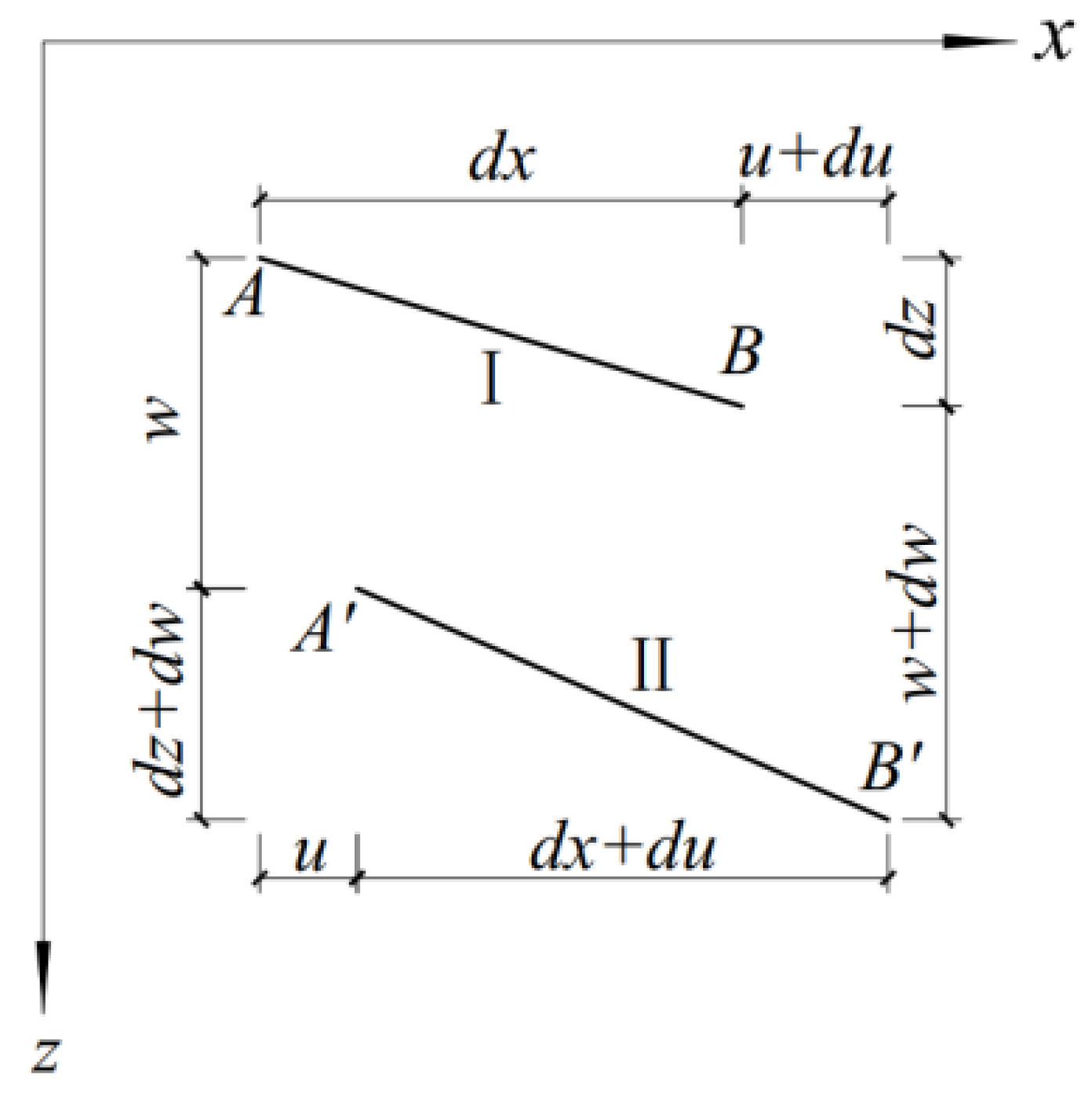
2.2. Deformation Coordination Equation

Figure 2 is a schematic diagram of the deformation microelement of the cable structure. The length of the cable is dx in the horizontal direction and dz in the vertical direction, and when the microelement AB is deformed from the initial position Ⅰ to position Ⅱ, its strain is as follows:
ε ( x ) = d x + d u 2 + d z + d w 2 d x 2 + d z 2 d x 2 + d z 2
The strain of a single cable under the upper load is small; Taylor’s formula is used to expand the square root in the above equation, and the first term of the trace is retained. By neglecting (du/dx)2 since u is a higher-order infinitesimal compared to x, the above equation can be simplified to Equation (2):
ε ( x ) = d u d x + d z d x d w d x + 1 2 d w d x 2 1 + d z d x 2
In terms of the prestressed cable structure, since its prestress P is much larger than the cable dead weight G, the cable can be regarded as a straight line in the initial state, and the sag of any point on it is 0, i.e., z(x) = 0. The above equation can be simplified to Equation (3):
ε x = d u d x + 1 2 d w d x 2
The cable is mainly subjected to vertical loads, so it is assumed that the horizontal component of cable force at any point on the cable is H. Under the upper load, the bending moment of the equivalent simply supported beam at any point along the span direction is M(x). Then, there is the following equilibrium condition at any point on the cable:
H z x + w x = M x
where z(x) is the initial morphology function of a cable, w(x) is the displacement function of a cable under the upper load.
For the prestressed cable structure, if the initial morphology of a cable is assumed to be a straight line, and the deformation of structure in its final morphology is noted as wN(x), then the horizontal tension of cable is the nominal horizontal tension, and HN is used to represent the nominal horizontal tension of cable, as shown in Figure 3a. Then, Equation (4) can be converted into Equation (5):
H N w N x = M x
If the axial stiffness of a cable is infinite, the elastic deformation of a cable can be neglected, i.e., w(x) = 0, as shown in Figure 3b. Therefore, the horizontal tension of cable is the rigid horizontal tension, and the rigid horizontal tension of cable is expressed in terms of Hf; Equation (4) can be transformed into Equation (6):
H f z x = M x
From Equation (6), it is clear that, if the initial condition and upper load of cable are known, the rigid horizontal tension Hf can be directly calculated from the equilibrium condition. According to the small strain assumption, the following equation holds for any point of a cable:
ε x = H 1 + d z d x 2 E A
By substituting Equation (7) into Equation (2) and Equation (3), respectively, the following two equations can be obtained:
H E A 1 + d z d x 2 3 2 = d u d x + d z d x d w d x + 1 2 d w d x 2
H N E A = d u d x + 1 2 d w N d x 2
A structural morphology parameter ξ [34] is introduced as shown in Equation (10); the deformation coordination equations of single-cable structure can be obtained by integrating the above two equations along the horizontal axis x-direction, as shown in Equations (11) and (12), which can be used to solve the forces and displacements of cable structures.
ξ = 1 l 0 l 1 + d z d x 2 3 2 d x
H l ξ E A = 0 l d z d x d w d x + 1 2 d w d x 2 d x
H N l E A = 1 2 0 l d w N d x 2 d x

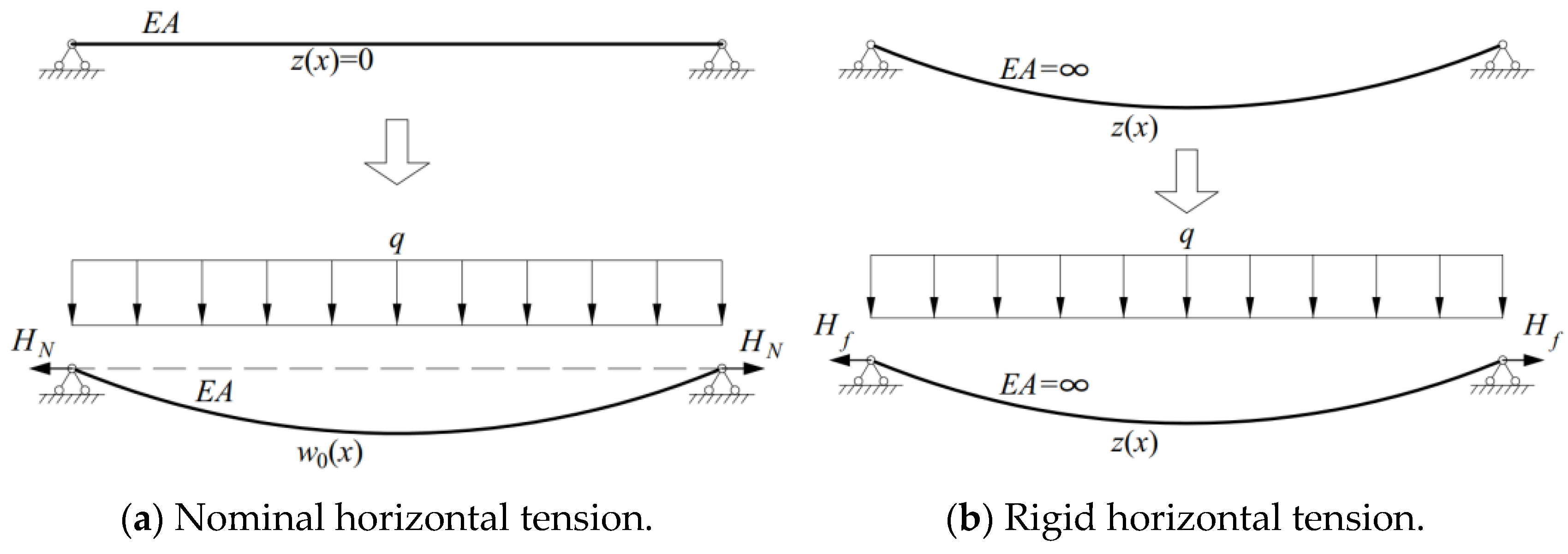
2.3. Analytical Formulations of Displacement and Cable Force

From Equation (4):
z x + w x = M x H
The cable morphology function is directly proportional to the bending moment of its equivalent simply supported beam. When z(x) ≠ 0, w(x) = αz(x), then it can be assumed according to the deformation characteristics of the cable structure; here, α is the displacement coefficient. Therefore, the following two formulations can be obtained:
z x = M x H 1 + α
w x = α M x H 1 + α
Substituting Equations (14) and (15) into the deformation coordination Equation (11), and substituting Equation (5) into Equation (12), the relationship between the cable force and its upper load can be obtained:
H l ξ E A = 2 α + α 2 2 H 2 1 + α 2 0 l d M x d x 2 d x
H N l E A = 1 2 H N 2 0 l d M x d x 2 d x
From Equation (17), it is clear that the nominal horizontal tension HN can be obtained; in other words, when the upper load is known, the horizontal tension of cable caused by the upper load can be solved directly by the following equation:
H N = E A 2 l 0 l d M x d x 2 d x 3
Substituting Equation (6) into Equation (14):
H 1 + α = H f
Substituting Equations (19) and (17) into Equation (16), the following equation can be obtained:
α + 1 α 2 + 2 α = H f 3 ξ H N 3
Converting the above equation from an equation about α to an equation about (α + 1), α can be solved as:
α = 1 + ξ H f 3 H N 3 3 1 1 1 3 1 + ξ H f 3 H N 3 2 3
According to Equations (5) and (6), the following equation is valid for any point on the cable structure:
H f H N = w N x z x
Substituting Equation (22) into Equation (21):
α = 1 + ξ w N 3 x z 3 x 3 1 1 1 3 1 + ξ w N 3 x z 3 x 2 3
If the displacement coefficient α << 1, in other words, if the deformation of the structure under the upper load is very small compared to the initial sag, w(x)/z(x) << 1, then Equation (21) can be simplified as:
α = 1 2 ξ H f 3 H N 3
According to the result of displacement coefficient α, analytical equations of H and w(x) can be obtained as follows:
H = H f 1 + α
w x = α z x
From the above analysis results, it can be seen that the solution of the cable force and displacement can be converted into the solution of the displacement coefficient α, which can be further decomposed into the solution of the two types of cable forces HN, Hf, and structural morphology parameter ξ. When the span and load conditions of the structure are known, the initial morphology function z(x) can be obtained; then, Hf can be directly obtained from the equilibrium condition, i.e., Equation (6); finally, ξ and HN can be obtained from Equations (10) and (18). z(x) and Hf reflect the initial morphology of the cable structure, and HN reflects cross-sectional properties of the cable structure. The three factors cover the main information of the cable structure, providing a simple conceptual design method for the determination and optimization of the initial morphology of the cable structure.

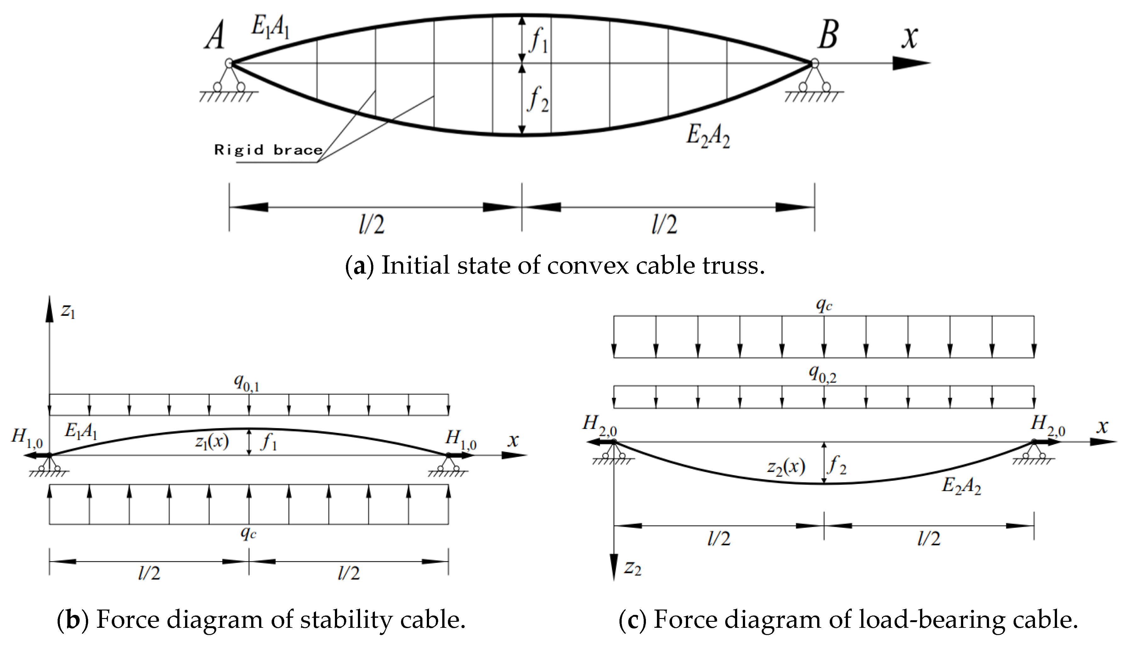
3. Analytical Formulation of Double-Layer Cable Flexible Photovoltaic Supports

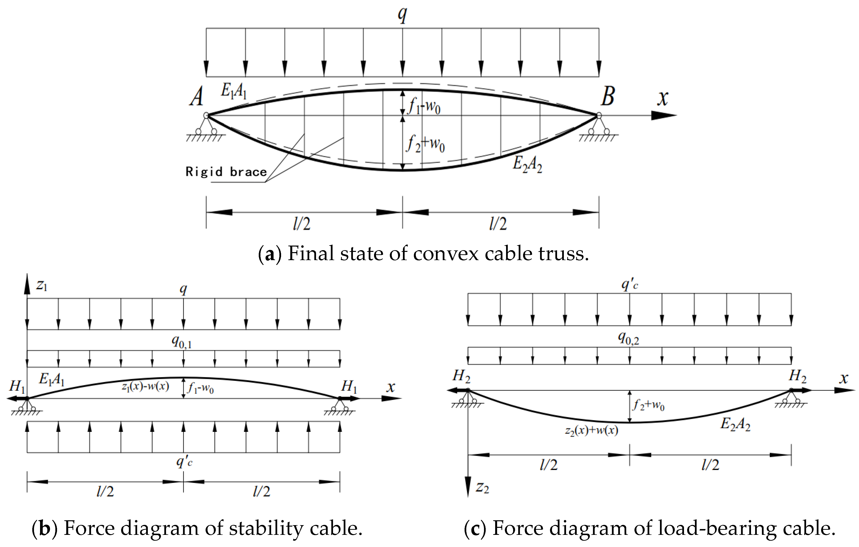
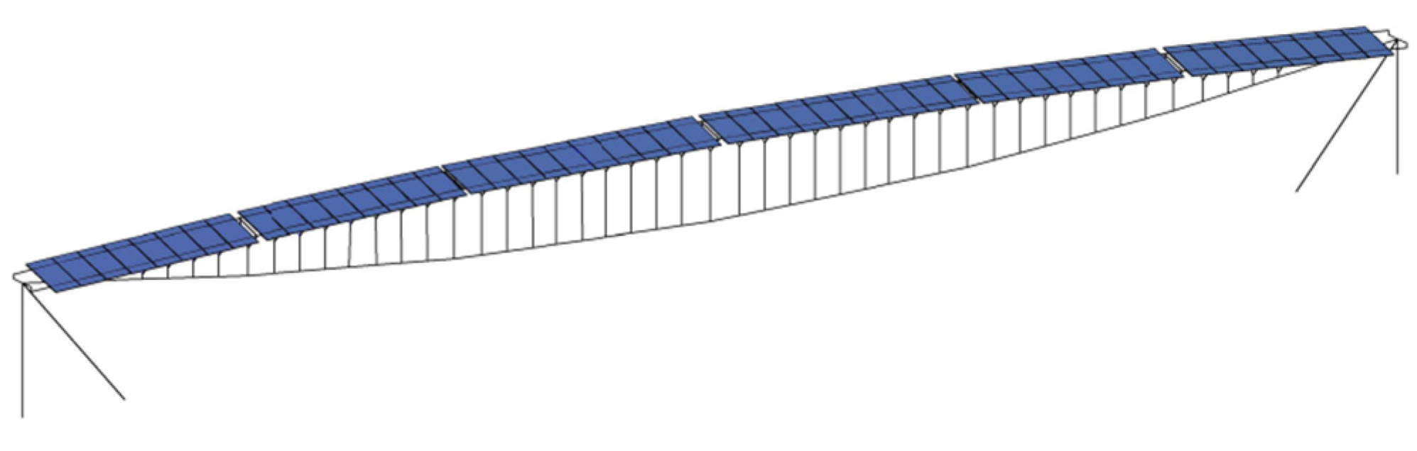
3.1. Structural Morphology and Load Assumption

The following three states of cable structures are defined in flexible photovoltaic supports:
(1)
Zero state: In this state, the cable only bears the initial prestress, without considering the effect of elastic elongation of the cable-on-cable force. It is assumed that cable force in this state is P.
(2)
Initial equilibrium state: The initial state refers to the self-equilibrium state of structure under prestress and dead weight. Assuming that the change in the cable length of the initial state from the zero state is Δs, and the cable force in this state is H0, through Hooke’s law, it can be deduced that H 0 = P + Δ s l E A .
(3)
The load equilibrium state, i.e., the final state, refers to the equilibrium state of structure under the external loads, assuming that the cable force in this state is H.
The morphology of the cable depends on the external loads, so the morphology of a single cable can be determined by the equilibrium condition. As shown in Figure 4, the equilibrium curves of the initial state of the cable vary under different upper loads. If the upper load is uniformly distributed along the span, then the cable morphology is a parabola. If the upper load is uniformly distributed along the length of cable, then the cable morphology is a catenary. Compared to the parabola, the use of a catenary to imitate the cable structure has higher accuracy, but this approach is also more computationally cumbersome. In the case of the sag-to-span ratio f/l ≤ 1/10, the difference in cable force and deformation is negligible, and the flexible photovoltaic support structure meets the above requirement, so the cable can be calculated by using a parabola. A parabola is used in the derivation of the cable length equation, and the cable length is calculated using Equation (27), where Lc is the length of the cable and f0 is the parabolic vector height.
s = L c + 8 f 0 2 3 L c
In fact, each photovoltaic module transmits the upper load to the cable in the form of concentrated forces through four fixture bolts. It is found that, if the number of compartments of the photovoltaic modules in cable length direction is greater than 3, the error of the single cable deflection and cable force is less than 5%, which is calculated according to the uniform distribution loads along the span compared with being a result calculated according to the concentrated loads. Therefore, it can be assumed that the upper load of the flexible photovoltaic support is uniformly distributed along the span, and the supports at both ends of the cable are equal in height and no support displacement occurs.

3.2. Analytical Formulation of Displacement

Under the structural dead weight and prestress, the initial morphology of the cable truss is shown in Figure 5. The elastic modulus of the stability cable and the load-bearing cable are E1 and E2, respectively, and the sectional areas of the cable are A1 and A2, respectively. The structure is divided into the upper and lower parts for stress analysis.
For the upper stability cable, the dead weight of the stability cable and photovoltaic module is the load q0,1, which is uniformly distributed along the span; the concentrated load on the stability cable is equivalent to the load qc, which is uniformly distributed along the x-axis direction; the initial morphology of the stability cable is z1(x); the initial tension is H1,0; the mid-span deflection of cable in the initial state is z1(l/2) = f1. For the lower load-bearing cable, the dead weight of the load-bearing cable and struts is the load q0,2 uniformly distributed along the span, and the concentrated load on the load-bearing cable is equivalent to the load qc uniformly distributed along the x-axis, and the initial morphology of load-bearing cable is z2(x), the initial tension is H2,0, and the mid-span deflection of cable in the initial state is z2(l/2) = f2.
The following equations are for the stability cable and the load-bearing cable, respectively:
H 1 , 0 d 2 z 1 d x 2 + q c q 0 , 1 = 0
H 2 , 0 d 2 z 2 d x 2 + q c + q 0 , 2 = 0
According to Equations (28) and (29), it can be obtained that:
H 1 , 0 d 2 z 1 d x 2 H 2 , 0 d 2 z 2 d x 2 q 0 , 1 q 0 , 2 = 0
Similar to the single-cable structure, the initial state parameters of the prestressed cable truss structure are recalculated according to Hooke’s law, the parabolic cable length equation, and the equilibrium condition under prestressing. Assuming that the struts between the stability cables and the load-bearing cables are absolutely rigid, i.e., the deflection changes of the upper and lower cables are equal, H1,0, H2,0, f1, and f2 in the new initial state are obtained by solving the nonlinear equations.
Under the load q uniformly distributed along the span direction, the balance diagram of the cable truss is shown in Figure 6. The structure departs from the dotted line position to the solid line position, assuming that the vertical displacement of the structure under the upper load is w(x), and the mid-span displacement of w(x) is denoted as w0. The cable force of the upper stability cable changes from H1,0 to H1, and the concentrated load on the stability cable is equivalent to the load qc, uniformly distributed along the x-axis, and the mid-span deflection of the stability cable in load equilibrium state is f1-w0. The cable force of the lower load-bearing cable changes from H2,0 to H2, and the mid-span deflection of the load-bearing cable in load equilibrium state is f2 + w0.
According to the single-cable theory, the equilibrium equation and deformation coordination equation of stability cable and load-bearing cable in this state are, respectively:
H 1 d 2 z 1 d x 2 d 2 w d x 2 + q c q 0 , 1 q = 0
H 2 d 2 z 2 d x 2 + d 2 w d x 2 + q c + q 0 , 2 = 0
H 1 H 1 , 0 l E 1 A 1 = 0 l 1 2 d w d x 2 d z 1 d x d w d x d x
H 2 H 2 , 0 l E 2 A 2 = 0 l 1 2 d w d x 2 + d z 2 d x d w d x d x
The balance equation of the whole cable truss can be obtained from Equations (31) and (32):
H 1 d 2 z 1 d x 2 d 2 w d x 2 H 2 d 2 z 2 d x 2 + d 2 w d x 2 q 0 , 1 q 0 , 2 q = 0
By combining the equilibrium Equations (30) and (35) of the initial equilibrium state and load equilibrium state, the second derivative of the vertical displacement w(x) of the structure under load q can be obtained as follows:
d 2 w d x 2 = H 1 H 1 , 0 H 2 H 2 , 0 q c + 1 H 1 H 1 , 0 q 0 , 1 + 1 H 2 H 2 , 0 q 0 , 2 + q H 2 H 1
The horizontal component H1,0, H1, H2,0, and H2 of the cable forces of the stability cable and the load-bearing cable in the initial and final states are independent of the horizontal coordinate x; the loads q, q0,1, q0,2, and qc are uniformly distributed along the span direction and they are independent of the horizontal coordinate x; it can be assumed that the displacement function w(x) is in the parabola form based on the upper loads and the initial geometric conditions. Assuming that the mid-span deflection of the stability cable and the mid-span deflection of the load-bearing cable in the initial state of the cable truss structure are f1 and f2, respectively, the initial geometric conditions of the stability cable and the load-bearing cable are as follows:
z 1 x = 4 f 1 l 2 x l x
z 2 x = 4 f 2 l 2 x l x
Substituting the above two equations into Equation (30):
8 l 2 f 2 H 2 , 0 f 1 H 1 , 0 q 0 , 1 q 0 , 2 = 0
According to Equations (36)–(38), the displacement function of cable truss under uniform load q can be set as:
w x = 4 w 0 l 2 x l x
By substituting Equations (37), (38) and (39) into Equations (33) and (34), respectively, the following equations can be obtained:
H 1 H 1 , 0 l E 1 A 1 = 8 w 0 2 3 l 16 f 1 w 0 3 l
H 2 H 2 , 0 l E 2 A 2 = 8 w 0 2 3 l + 16 f 2 w 0 3 l
By substituting Equations (39), (40), (41) and (42) into Equation (35), respectively, the following equation can be obtained:
8 3 l 2 E 1 A 1 + E 2 A 2 w 0 3 + 8 l 2 E 2 A 2 f 2 E 1 A 1 f 1 w 0 2   + H 1 , 0 + H 2 , 0 + 16 3 l 2 E 1 A 1 f 1 2 + E 2 A 2 f 2 2 w 0 = q l 2 8
It is very complicated to solve the unary cubic equation in Equation (43) with respect to w0. Since the structural deformation is a small amount compared to the span l, the quadratic and cubic terms of w0 in the above equation can be neglected and simplified by denoting (E2A2f2E1A1f1) as β, (E1A1f12 + E2A2f22) as γ, and (H1,0 + H2,0) as H0:
w 0 = 3 q l 4 128 γ + 24 H 0 l 2
Calculations with higher accuracy can be obtained if only the cubic term of w0 is ignored:
w 0 = l 4 H 0 2 + 256 9 γ 2 + 32 3 H 0 l 2 γ + 4 q l 4 β 16 β l 2 H 0 16 β γ 3 β

3.3. Analytical Formulation of Cable Force

By substituting w0 into the deformation coordination equation, i.e., Equations (41) and (42), the cable forces H1 and H2 of stability cable and load-bearing cable under uniform load q are obtained. In addition, H1 and H2 can also be calculated by means of unstressed length. Taking the horizontal component H2 of the load-bearing cable force in the load equilibrium state as an example, we will demonstrate here.
In the initial state, assuming that the cable force (prestress) of the load-bearing cable is P2, the coefficient of thermal expansion of cable is α, and the mid-span deflection of the load-bearing cable in initial state is known to be f2,0 as shown in Figure 7, then the unstressed length of the load-bearing cable can be obtained by the parabolic length equation. The unstressed length is as follows:
P 2 = α E 2 A 2 Δ T s 0 = l + 8 f 2 , 0 2 3 l P 2 l E 2 A 2 = l + 8 f 2 , 0 2 3 l α l Δ T
where P2 is the prestress applied in the form of temperature, and ΔT is the temperature change.
In the load equilibrium state, the mid-span deflection of the load-bearing cable is f2,0 + w0, which is denoted as f2. At this condition, the morphology of the load-bearing cable is a parabola, and the horizontal component of the cable force at any position is equal, denoted as H2. The cable force at any position of the load-bearing cable in the final state can be calculated from the morphology function z(x) of the final state and the horizontal component H2 of the cable force. By integrating the elastic elongation of the cable caused by the cable force in the span direction, the following equations can be obtained:
z x = 4 f 2 l 2 x l x Δ s = 0 l H 2 E 2 A 2 cos 2 θ d x
where θ is the angle between the tangent line at any point within the load-bearing cable and the x-axis in the positive direction.
Therefore, Equation (48) can be established according to the variation of load-bearing cable length relative to unstressed cable length in the load equilibrium state as follows:
s = l + 8 f 2 2 3 l s s 0 = Δ s
According to the above equation, the horizontal component H2 of the cable force in the final state of the load-bearing cable can be sorted out:
H 2 = E 2 A 2 8 l 2 f 2 2 f 2 , 0 2 + 3 α l 4 Δ T 3 l 4 + 16 f 2 2 4 l 2 6 l + 3
In the same way, the horizontal component H1 of the cable force in the final state of the stability cable can be sorted out:
H 1 = E 1 A 1 8 l 2 f 1 2 f 1 , 0 2 + 3 α l 4 Δ T 3 l 4 + 16 f 1 2 4 l 2 6 l + 3

4. The Finite Element Verification of Analytical Formulation

4.1. Finite Element Model

Figure 8 shows the cable truss flexible photovoltaic support structure with a span of 63 m; the diameters of stability cable and load-bearing cable are 19.3 mm and 28.6 mm, respectively; the sectional areas are A1 = 0.000244 m2 and A2 = 0.000532 m2; the elastic modulus is E = 1.95 × 10¹¹ N/m2; the density is 7850 kg/m3; the coefficient of thermal expansion is α = 1.2 × 10⁻⁵/°C; the gravitational acceleration is 9.806 N/kg. The mass of the photovoltaic module is distributed to each load-bearing cable about 13 kg/m according to the structural span, and a rigid brace is arranged every meter between the stability cable and the load-bearing cable.
The stability cable arches upward in the initial state of the cable truss structure, and the mid-span vector height is f1 = 1.26 m; the mid-span sag of the load-bearing cable is f2 = 2.52 m. Taking the mid-span sag of the load-bearing cable as the verification index, the structural dead weight is converted into an equivalent line load q0 = 333.5 N/m on the load-bearing cable. According to the actual working conditions, the vertical downward variable load q1 = 800 N/m and vertical upward variable load q2 = 500 N/m are applied to each upper stability cable, respectively. Under each variable load, the temperature increases by 30 °C and decreases by 30 °C, respectively. The six load cases are shown in Table 1.
In the structural finite element calculation model, Link180 is used for cable and Beam188 is used for rigid brace. All other elements except cable and brace are killed, and fixed constraints are set at both ends of the cable. First, the horizontal component of the cable force of the stability cable is set in the analytical formulation, H1,0, and then the prestress distribution of the stability cable and the load-bearing cable can be calculated from the initial position function of cable. The prestress should ensure that no slack occurs in both layers of cables under variable loads q1 and q2.

4.2. Comparison of Finite Element Calculation Results
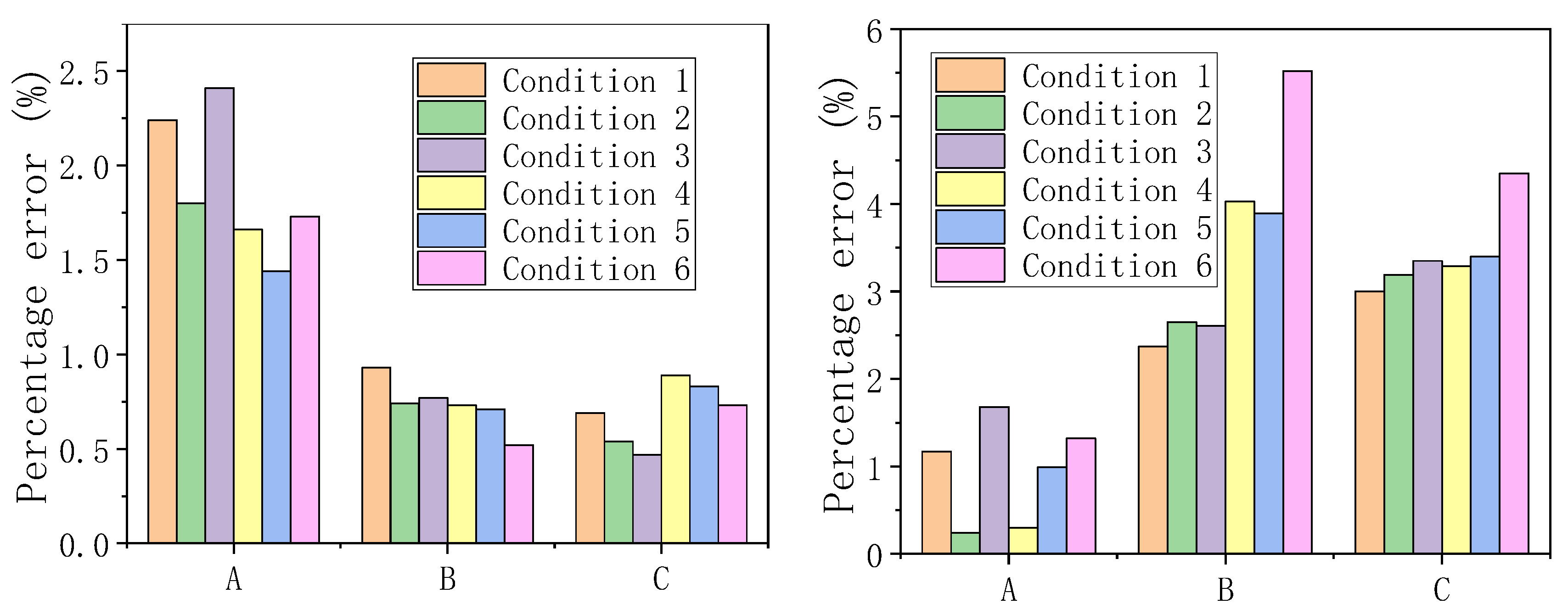
The nonlinear analysis of 63 m span cable truss structure is conducted, and the results are compared with theoretical calculation results to verify the accuracy of the analytical formulations. The displacement and cable force equation obtained in the previous chapter are verified by taking the deformation of the mid-span and the horizontal component of the cable force in the load equilibrium state as the verification indexes.

4.2.1. Displacement

The results of finite element calculation and analytical formulation calculation are listed in Table 2.
As can be seen from Table 2 and Figure 9, with the improvement of the theoretical accuracy of the analytical solution, the gap between the structural mid-span deformation calculated by the analytical formulation and the finite element results gradually decreases. Compared with only considering the linear term, if the linear term and the quadratic term are considered at the same time in the analytical formulation, then the accuracy of the analytical solution can be greatly improved, so that the gap between them is controlled within 3%. If all the terms are considered, then the error is less than 2%. In addition, cases 1, 2, and 3 are more sensitive to the accuracy of analytical solutions, and cases 4, 5, and 6 are less sensitive.

4.2.2. Cable Force

The horizontal components H2 and H1 of the load-bearing and stability cable forces in the load equilibrium state are calculated by substituting the three kinds of structural mid-span displacements w0 with different analytical accuracies, seen in Table 2, into Equations (49) and (50), respectively. The finite element results and the three accuracy results for analytical formulations are listed in Table 3.
It can be seen from Table 3 and Figure 10 that the cable force equation has excellent accuracy. The stability cable force H1 is closer to the finite element result when the quadratic and cubic terms are considered, and the load-bearing cable force H2 is closer to the finite element result when only the linear term is considered. The stability cable force error can be controlled within 1%, and the load-bearing cable force error can be controlled within 4%. When the initial and the final morphology of the cable truss structure is known, the horizontal component of the cable force in the final state can be calculated directly according to the prestress P in the initial state.

5. Mathematical Model of Optimization of the Initial Morphology

5.1. Optimization Objective

In the design of the flexible photovoltaic support, the stability, bearing capacity, and wind-resistant performance can be improved by optimizing the initial morphology of the support structure, so as to improve the power generation efficiency and service life of the photovoltaic module. According to the analytical formulation, it can be seen that there are numerous design variables for the optimization of the structure’s morphology of the flexible photovoltaic support, including the structure shape, cable section, prestress level, etc. Therefore, it is still difficult to establish a comprehensive and overall optimization objective function. According to the fully stressed design method, under the premise that the deformation of the structure meets the deflection limit, the structural performance of the cable should be maximized, i.e., the cross-sectional dimensions of the cable should be reduced as much as possible to achieve the lightest weight. From the perspective of engineering economy, the cable force not only directly determines the cable specifications, but also indirectly affects the specifications selection of steel components connected with the cable. In order to simplify the structural optimization design process, the morphological optimization problem of the flexible photovoltaic support structure was simplified to a function problem with the single objective of reducing the cable force, some structural design parameters other than the optimization variables were set as known, and the optimal solution was obtained through the nonlinear programming method.

5.2. Optimization Variable

The CTFPS structure has three independent optimization variables, which are the vector height f1 of the stability cable in the initial state, the sag f2 of the load-bearing cable in the initial state, and the cable force H1,0 in the initial state. Based on the above optimization objective, f1 is set as a known quantity, f2 and H1,0 are taken as the optimization variables; the relationship between the optimization variables and optimization objectives is established through constraint conditions, so as to obtain the minimum solution of the sum of the upper and lower tension forces of the CTFPS structure under the condition that the stability cable vector height is known, i.e., to achieve the final optimization objective.

5.3. Constraint Condition

There are three constraints for the optimization of the initial morphology of the CTFPS structure:
(1)
The maximum deformation of the structure meets the deflection control requirements.
(2)
In the serviceability limit state, the lower cables of cable truss structure are allowed to relax, while the upper cables are not allowed to relax.
(3)
In the ultimate limit state, the cables meet the strength limit requirements.

5.4. Load Case

As shown in Table 4, the standard value of permanent action is G; the standard value of snow load is Q s k ; the standard value of wind pressure load is Q w k + ; the standard value of wind suction load is Q w k ; the heating effect is Q t k + ; the cooling effect is Q t k . SC-1 and SC-2 are the standard combined cases of the most unfavorable load in the serviceability limit state, and DC-1 and DC-2 are the basic combined cases of the most unfavorable load in the ultimate limit state.

5.5. The Mathematical Model of Structural Optimization

Assume that the sectional areas of the stability cable and the bearing cable are A 1 1 and A 2 1 , respectively, where A 1 1 is the total sectional area of the two stability cables. The equivalent line load of the dead weight of the cable is q c 1 , and the equivalent line load on the load-bearing cable converted by the dead weight of the photovoltaic module is qp, so the equivalent line load of the structure dead weight is q 0 1 = q c 1 + q p . According to Equation (43), it can be seen that the structural mid-span deflection is determined by the variable loads, so the two standard combinations of variable loads are denoted as q1 and q2, i.e., q 1 = q w + + q s , q 2 = q w + q t + . The two basic combinations of variable loads are denoted as q 1 and q 2 , i.e., q 1 = 1.5 q w + + 1.05 q s , q 2 = 1.5 q w + 0.9 q t .
Since the structural optimization design can only be conducted when the load conditions are clear, and the prestress as a special self-balancing load, its distributions are not unique when the constraint conditions are met, so the prestress should be determined first before the structural optimization design:
(1)
Firstly, the minimum prestress H1,0 and H2,0, satisfying the constraint conditions, are determined according to the fact that the cable cannot relax under any standard load combination. When the structure is subjected to a downward load q1, it is assumed that the structural deformation reaches the maximum limit [Δ]; at the same time, the upper stability cables still need to have a certain amount of cable stress, i.e., the minimum allowable stress, σ1,min. Equation (51) can be obtained by substituting them into Equation (41). If the vector height f1 in the initial state of the stability cable is known, then H1,0,min are deterministic quantities. In the same way, the minimum prestress H2,0,min of the lower load-bearing cable can be calculated when the structure is subjected to the upward load q2.
H 1 , 0 , min = σ 1 , min A 1 1 8 Δ Δ 2 f 1 E A 1 1 3 l 2 H 2 , 0 , min = σ 2 , min A 2 1 8 Δ Δ 2 f 2 E A 2 1 3 l 2
The larger of q1 and q2 is the load condition under which the structure has the maximum deformation [Δ]. We assume that q1 is the larger of the two values for the establishment of the subsequent structural optimization model.
(2)
According to the equilibrium conditions of the initial state, the following equation can be established:
f 2 H 2 , 0 = f 1 H 1 , 0 , min + q 0 1 l 2 8
By substituting the above equation into Equation (44), the initial sag f2 of the load-bearing cable can be calculated under variable load q1, when the deformation reaches the maximum limit [Δ], as shown in Equation (53). Under this condition, the deformation of the structure is the largest and the stiffness is the weakest, so f2 is the minimum possible value under the condition that the deformation limit of the structure is met.
16 E A 2 1 3 l 2 f 2 3 + H 1 , 0 , min + 16 E A 1 1 f 1 2 3 l 2 q 1 l 2 8 Δ f 2 + H 1 , 0 , min f 1 + q 0 1 l 2 8 = 0
(3)
Following the previous two steps, the initial morphology of the cable truss can be obtained under the condition that the maximum deflection control index is met. If the lower load-bearing cable is not allowed to relax in the serviceability limit state, it is necessary to check whether the load-bearing cable force H2 meets the allowable minimum stress requirements under the upward variable load q2. If it does not meet the requirements, it is necessary to increase H2,0 and H1,0, correspondingly. Finally, the bearing capacity of the stability cable and the load-bearing cable is checked. According to Equation (43), the deformation of the structure under the basic combination q 1 and q 2 is calculated, and the maximum cable force H 2 of the load-bearing cable under the load q 1 and the maximum cable force H 1 of the stability cable under the load q 2 are calculated according to the deformation. If both H 1 and H 2 do not exceed the design bearing capacity corresponding to the selected cable size, the iteration is terminated. Otherwise, the cable area is increased and the iterative solution is continued.

6. Example of Optimization of the Initial Morphology

According to the above optimization model, combined with a flexible photovoltaic support project, the optimization of the initial morphology is carried out. A CTFPS structure is buit: span l = 63 m; two standard combinations of variable loads, q 1 = 1300   N / m and q 2 = 1100   N / m ; two basic combinations of variable loads, q 1 = 2000   N / m and q 2 = 1700   N / m . For the upper stability cable, it is not allowed to relax in serviceability limit state, and 5% of the breaking force of the stability cable is taken as the minimum allowable cable force. For the lower load-bearing cable, there are two cases to consider: the first case does not allow it to relax in serviceability limit state, 5% of the load-bearing cable breaking force is taken as the minimum allowable cable force, and the structural deflection limits are taken as l/250, l/200, l/150, and l/100, respectively; the second case allows the load-bearing cable to relax under the wind suction load, the single-layer cable theory is used to calculate the upper layer of the stability cable, the downward deflection deformation limit of structure are taken as l/250, l/200, l/150, and l/100, and the upward deflection deformation limit under the wind suction load was taken as l/30.

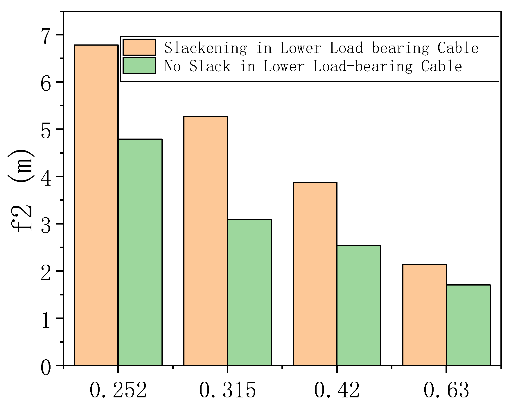
6.1. No Slack in Lower Load-Bearing Cable

It can be seen that q 1 is the loading condition in which the maximum deformation [Δ] of the structure occurs, assuming that the vector height of the stability cable in the initial equilibrium state f1 = l/50 = 1.26 m. The four maximum allowable deformations of the structure are taken, respectively, for structural optimization, and the final optimization results of the structure under the four deflection limits are shown in Table 5. From the results of the optimization, it can be seen that, as the deflection limit increases, the initial sag f2 of the load-bearing cable decreases significantly and the thickness of the structure also decreases continuously. However, in order to meet the minimum allowable cable force of the lower-bearing cable, the cable force in the initial equilibrium state is increasing, and the specifications of the load-bearing cable are also increasing. Due to the existence of the equilibrium relationship shown in Equation (52), in the initial equilibrium state of the structure, the stability cable specification decreases as the deflection limit increases.

6.2. Slackening in Lower Load-Bearing Cable

It can be seen that a larger specification of load-bearing cable is required to ensure that the lower load-bearing cable always meets the constraints of the allowable minimum force in the serviceability limit state from Table 5. In order to effectively reduce construction costs, it is suggested to allow the lower load-bearing cables to relax in the serviceability limit state.
If the lower bearing cable relaxes under wind suction load, the upward deflection deformation Δ2 of the upper stability cable and the horizontal component H1 of the cable force are calculated according to the single-cable theory. The Δ2 is set to l/30 according to the deformation limit of the single-cable structure. The maximum allowable deformation [Δ] of the structure is taken as l/250, l/200, l/150, and l/100, respectively. The final optimization results of the structure under the four deflection deformation limits are shown in Table 6. In the literature [8], the results show that, under wind suction load, the load-bearing cables will relax and fail, and the load is mainly born by the stability cables; under wind pressure load, the load is born by the stability cables and the load-bearing cables together, but the effect of the initial tension of the load-bearing cables on the displacement of the trusses is more obvious, and the vector height of the stability cables can effectively reduce the displacement of the trusses under the wind suction load. As can be seen from Table 6 and Figure 11, with an increase in the deflection deformation limit value, the specifications of the load-bearing cable still show an increasing trend, and their initial sag f2 gradually decreases; the cable length also shortens accordingly. However, if the lower load-bearing cables are allowed to relax under wind suction load, the specifications of the cable can be effectively reduced, with comparison to ensure that the lower load-bearing cables are always in a tense state under the serviceability limit state, which is mutually confirmed with the research findings in [7]. The literature research results show that the deflection tolerance value of the main cable and the secondary cable of the flexible cable-suspended photovoltaic supports is recommended to be L/150 and L/50, respectively. Compared with the research results of this paper, the increase in the deflection limit value will increase the specification of load-bearing cables, but at the same time, it can effectively reduce the thickness of the structure and the length of the cables. To summarize, it is recommended that the deflection limit for the CTFPS structure should be 1/100 of the single span.

6.3. Economic Discussion

The flexible photovoltaic support structure is extremely sensitive to economy; when designing and selecting the photovoltaic support structure, it is necessary to minimize material consumption under the premise of the strength and structure stability, so as to reduce the overall project cost. For the CTFPS structure, the deflection value of the structure is mostly controlled by pre-arching the upper cable. Table 7 shows the results of optimizing the initial morphology of the structure by setting the pre-arched height f1 of five kinds of upper stability cables at equidistance between 0 and l/50, and allowing the lower load-bearing cables to relax in the serviceability limit state.
It can be seen from Table 7 that increasing the structural thickness and the cable prestress can reduce the deflection deformation of the structure; cable quality is mainly affected by cable specifications, and is not sensitive to changes in structural thickness; the pre-arch of the upper stability cable can effectively reduce the structural deflection, but can also increase the total thickness of the structure; under the same cable specifications, the greater the arch amount, the greater the total thickness of the structure.

7. Conclusions

(1)
Based on the theory of cable structure design, the relationship between morphology and internal force of single-cable structure is deduced, and the analytical method for solving the internal force and displacement of CTFPS structure under uniform load is provided. By comparing to the results of finite element analysis, the error of displacement is less than 3%, and the error of the cable force is less than 4%, which verifies the accuracy of the analytical formulations.
(2)
So far, there is no relevant specification to stipulate a reasonable value range of deflection deformation of flexible photovoltaic support, this paper establishes a finite element analysis model of the flexible photovoltaic support structure and analyzes the cable force and displacement under the static action. It is suggested that the deflection deformation of the double-layer cable truss structure should be taken as 1/100 of the single span.
(3)
According to the analytical formulations, a mathematical model for optimizing the initial morphology is proposed with the objective of reducing the construction cost of flexible photovoltaic supports, which achieves the optimization objective of minimizing the cable force, i.e., minimizing the cable specification.
(4)
For CTFPS structure, compared with ensuring that the lower load-bearing cable is always in the tension state under serviceability limit state, allowing it to relax under wind suction load can effectively reduce the cable specification. Therefore, it is recommended that the lower load-bearing cable is allowed to relax during the structural design.
(5)
For CTFPS structures, the stability cables can be pre-arched to bring their mid-span vector height up to the deflection deformation limits. With the increase in the prestress of the load-bearing cable, the brace height required to maintain the structural deformation limit decreases gradually, but the specification of the load-bearing cable increases accordingly. Therefore, when choosing the most economical morphology, it is necessary to comprehensively consider the cost of both steel structure and cables, and it is recommended that the total height of the mid-span should be between 1/20 and 1/15 of the single span of the structure.

Author Contributions

Writing—review and editing, Z.D. and B.L.; Formal analysis, Z.D. and B.L.; Methodology, F.W.; Data curation, F.W. and X.D.; Software, H.Y. and X.L.; Validation, H.Y.; Writing—original draft, X.D.; Investigation, X.L.; Funding acquisition, X.L.; Resources, X.L. All authors have read and agreed to the published version of the manuscript.

Funding

This research received no external funding.

Data Availability Statement

The data used in this study are not publicly available due to confidentiality and privacy concerns. Access to the data can only be granted upon request and with the permission of the appropriate parties. Please contact the corresponding author for further information.

Conflicts of Interest

Author Xin Liu was employed by the company Nanjing Dong-Da Modern Prestressed Engineering Co., Ltd. The remaining authors declare that the research was conducted in the absence of any commercial or financial relationships that could be construed as a potential conflict of interest.

References

  1. Jiang, F.; Shang, R.; Sun, Y. Tension and Deformation Analysis of Suspension Cable of Flexible Photovoltaic Support under Concentrated Load with Small Rise-span Ratio. J. Phys. Conf. Ser. 2022, 2381, 12069. [Google Scholar] [CrossRef]
  2. Ding, H.; He, X.; Jing, H.; Wu, X.; Weng, X. Design Method of Primary Structures of a Cost-Effective Cable-Supported Photovoltaic System. Appl. Sci. 2023, 13, 2968. [Google Scholar] [CrossRef]
  3. Desai, Y.M.; Popplewell, N.; Shah, A.H.; Buragohain, D.N. Geometric nonlinear static analysis of cable supported structures. Comput. Struct. 1988, 29, 1001–1009. [Google Scholar] [CrossRef]
  4. Bartholet, F.P.; Büchel, A. Solar Wings a new Lightweight PV Tracking System. In Proceedings of the 23rd European Photovoltaic Solar Energy Conference and Exhibition, Valencia, Spain, 1–5 September 2008. [Google Scholar]
  5. Li, Z.; Zhai, J.; Wu, C.; Wang, Y.; Zhang, P.; Jiang, S.; Guo, Z. Parametric Analysis of Structural Design of Flexible Photovoltaic Supports with Single-Layer Cable System. J. Taiyuan Univ. Technol. 2024. [Google Scholar]
  6. Zhang, L.; Zhao, J.K. Analysis of the Effects of Initial Tension and Upper Arch of Cords on Internal Forces and Structural Displacements of Cords in Flexible Photovoltaic Supports with Cord Trusses. In Proceedings of the 2024 Conference on Seismic Technology for Engineering Structures, Kunming, China, 2–4 August 2024. [Google Scholar]
  7. Du, Z.; Meimeti Aili, A.; Ma, X.; Zhao, Y.; Du, Y.; Zhi, C. Research on Structural Selection and Static Performance Analysis of Flexible Photovoltaic Supports. Build. Technol. 2024, 55, 1777–1782. [Google Scholar] [CrossRef]
  8. Yuan, H.-X.; Song, J.-M.; Du, X.-X.; Wang, R.-L.; Ma, W.-Y. Study on the Structural Stress Performance of Flexible Photovoltaic Supports with Double-Layer Cable System. J. Shenyang Univ. Archit. (Nat. Sci. Ed.) 2024, 40, 395–403. [Google Scholar]
  9. He, X.; Ding, H.; Jing, H.; Wu, X.; Weng, X. Mechanical characteristics of a new type of cable-supported photovoltaic module system. Sol. Energy 2021, 226, 408–420. [Google Scholar] [CrossRef]
  10. Shen, W.; Zeng, Y.; Zhang, W.; Tang, Z.; Xie, H. Structural design and simulation analysis of fixed adjustable photovoltaic support. J. Comput. Methods Sci. Eng. 2023, 23, 1409–1423. [Google Scholar] [CrossRef]
  11. Kilikevicius, A.; Cereska, A.; Kilikevicien, K. Analysis of external dynamic loads influence to photovoltaic module structural performance. Eng. Fail. Anal. 2016, 66, 445–454. [Google Scholar] [CrossRef]
  12. Bao, T.; Li, Z.; Pu, O.; Chan, R.W.K.; Zhao, Z.; Pan, Y.; Yang, Y.; Huang, B.; Wu, H. Modal analysis of tracking photovoltaic support system. Sol. Energy 2023, 265, 112088. [Google Scholar] [CrossRef]
  13. Tang, J.F.; Lin, J.P.; Huo, J.S. Structural Characterisation of Flexible Photovoltaic Supports and Their Optimal Design. J. Huaqiao Univ. (Nat. Sci. Ed.) 2019, 40, 331–337. [Google Scholar]
  14. Chen, F.; Zhu, Y.; Wang, W.; Shu, Z.; Li, Y. A Review on Aerodynamic Characteristics and Wind-Induced Response of Flexible Support Photovoltaic System. Atmosphere 2023, 14, 731. [Google Scholar] [CrossRef]
  15. Xu, H.; Ding, K.; Shen, G.; Du, H.; Chen, Y. Experimental investigation on wind-induced vibration of photovoltaic modules supported by suspension cables. Eng. Struct. 2024, 299, 117125. [Google Scholar] [CrossRef]
  16. Liu, J.; Li, S.; Luo, J.; Chen, Z. Experimental study on critical wind velocity of a 33-meter-span flexible photovoltaic support structure and its mitigation. J. Wind. Eng. Ind. Aerodyn. 2023, 236, 105355. [Google Scholar] [CrossRef]
  17. Li, J.; Hong, G.; Xu, H. Wind Load Effects and Gust Loading Factor for Cable-Suspended Photovoltaic Structures. Energies 2024, 17, 38. [Google Scholar] [CrossRef]
  18. Abiola-Ogedengbe, A.; Hangan, H.; Siddiqui, K. Experimental investigation of wind effects on a standalone photovoltaic (PV) module. Renew. Energy 2015, 78, 657–665. [Google Scholar] [CrossRef]
  19. Jubayer, C.M.; Hangan, H. Numerical simulation of wind effects on a stand-alone ground mounted photovoltaic (PV) system. J. Wind. Eng. Ind. Aerodyn. 2014, 134, 56–64. [Google Scholar] [CrossRef]
  20. Alan, G.; Davenport, A.A. Gust Loading Factors. J. Struct. Div. 1967, 93. [Google Scholar] [CrossRef]
  21. Tamura, Y.; Kim, Y.C.; Yoshida, A.; Itoh, T.; Feltrin, G. Wind-induced vibration experiment on solar wing. MATEC Web Conf. 2015, 24, 4006. [Google Scholar] [CrossRef]
  22. Kim, Y.C.; Tamura, Y.; Yoshida, A.; Ito, T.; Shan, W.; Yang, Q. Experimental investigation of aerodynamic vibrations of solar wing system. Adv. Struct. Eng. 2018, 21, 2217–2226. [Google Scholar] [CrossRef]
  23. Tan, Y.J.; Zheng, X.X.; Zhao, C.X.; Jin, S.H.; Ma, W.Y. Wind vibration response of a single-layer prestressed suspension photovoltaic support. Wind vibration response analysis of single-layer prestressed suspension photovoltaic supports. J. Wuhan Univ. (Eng. Ed.) 2022, 55, 68–71. [Google Scholar]
  24. Finotto, V.C.; Da Silva, W.R.L.; Valášek, M.; Atemberk, P. Hybrid fuzzy-genetic system for optimising cabled-truss structures. Adv. Eng. Softw. 2013, 62–63, 85–96. [Google Scholar] [CrossRef]
  25. Ma, S.; Yuan, X.; Deng, M.; Yang, L. Minimal mass design of a new cable truss in two states. Mech. Res. Commun. 2022, 125, 103995. [Google Scholar] [CrossRef]
  26. Barbón, A.; Bayón-Cueli, C.; Bayón, L.; Carreira-Fontao, V. A methodology for an optimal design ofground-mounted photovoltaic power plants. Appl. Energy 2022, 314, 118881. [Google Scholar] [CrossRef]
  27. Li, X.; Zhu, J.; Wang, J.; Zhang, W. Topology optimization for prestressed cable-truss structure considering geometric nonlinearity. Struct. Multidiscip. Optim. 2023, 66, 201. [Google Scholar] [CrossRef]
  28. Lou, Y.; Zhang, J.; Pan, Y. Static and Dynamic Response Analysis of Flexible Photovoltaic Mounts. Buildings 2024, 14, 2037. [Google Scholar] [CrossRef]
  29. Wang, X.; Ji, G.; Gu, H.; Lv, S.; Ni, H.; Wang, P.; Chen, K.; Meng, Y. Research and Design of Fixed Photovoltaic Support Structure Based on SAP2000. MATEC Web Conf. 2018, 166, 3002. [Google Scholar] [CrossRef]
  30. Li, X.; Xue, S.; Li, X. Prestress design and geometric correction method of cable-truss structures based on equivalent equilibrium force model. Thin-Walled Struct. 2023, 191, 111058. [Google Scholar] [CrossRef]
  31. Barbón, A.; Carreira-Fontao, V.; Bayón, L.; Silva, C.A. Optimal design and cost analysis of single-axis tracking photovoltaic power plants. Renew. Energy 2023, 211, 626–646. [Google Scholar] [CrossRef]
  32. Chen, Z.; Cao, H.; Zhu, H.; Hu, J.; Li, S. A simplified structural mechanics model for cable-truss footbridges and its implications for preliminary design. Eng. Struct. 2014, 68, 121–133. [Google Scholar] [CrossRef]
  33. JGJ257-2012; Technical Specification for Cable Structures. China Construction Industry Press: Beijing, China, 2012; Volume 42, p. 136.
  34. Huang, Z.Y. Conceptual Design Study on Performance and Morphology of Suspension Structures; China Academy of Building Research Ltd.: Shenzhen, China, 2022. [Google Scholar]
Figure 1. Two types of photovoltaic supports.
Buildings 14 02549 g001
Figure 2. Deformation microelement of single-cable structure.
Buildings 14 02549 g002
Figure 3. Schematic diagrams of two ideal states.
Buildings 14 02549 g003
Figure 4. Cable morphology under two types of upper loads.
Buildings 14 02549 g004
Figure 5. Initial state calculation diagram of prestressed cable truss.
Buildings 14 02549 g005
Figure 6. Final state calculation diagram of prestressed cable truss.
Buildings 14 02549 g006
Figure 7. Calculation diagram of unstressed cable length method.
Buildings 14 02549 g007
Figure 8. Visualization of 63 m span cable truss flexible photovoltaic support structure.
Buildings 14 02549 g008
Figure 9. Analytical solution accuracy of each load case.
Buildings 14 02549 g009
Figure 10. Analytical solution accuracy of each load case.
Buildings 14 02549 g010
Figure 11. Initial sag of load-bearing cable.
Buildings 14 02549 g011
Table 1. Load cases.
Case NumberLoad Combination
1Downward load q1
2Downward load q1 and temperature effect (−30 °C)
3Downward load q1 and temperature effect (+30 °C)
4Upward load q2
5Upward load q2 and temperature effect (−30 °C)
6Upward load q2 and temperature effect (+30 °C)
Table 2. Comparison of displacement in mid-span between analytical and finite element results.
Structural ResponseCase NumberAnalytical ResultFinite Element ResultPercentage Difference
Mid-span Displacement
w0/m
1A−0.4934−0.45089.45%
B−0.45701.36%
C−0.4504−0.09%
2A−0.4448−0.40928.72%
B−0.41300.93%
C−0.4070−0.53%
3A−0.5404−0.49499.19%
B−0.49900.83%
C−0.4918−0.62%
4A0.30840.3218−4.17%
B0.32701.63%
C0.32390.64%
5A0.33020.3395−2.75%
B0.34601.92%
C0.34341.13%
6A0.28860.3024−4.56%
B0.31042.67%
C0.30671.42%
Note: A, B, and C are the three accuracy solutions for analytical formulations, considering only the linear term, considering the linear and quadratic terms, and considering all terms, respectively.
Table 3. Comparison of cable force between analytical and finite element results.
Structural ResponseCase NumberAnalytical ResultFinite Element ResultPercentage Difference
H1/kN1A259.7265.7−2.24%
B263.2−0.93%
C263.9−0.69%
2A298.5304.0−1.80%
B301.8−0.74%
C302.4−0.54%
3A221.3226.8−2.41%
B225.1−0.77%
C225.7−0.47%
4A373.4379.8−1.66%
B377.0−0.73%
C376.4−0.89%
5A411.4417.4−1.44%
B414.5−0.71%
C414.0−0.83%
6A335.9341.8−1.73%
B340.0−0.52%
C339.3−0.73%
H2/kN1A398.1393.51.17%
B384.2−2.37%
C381.7−3.00%
2A415.3414.30.24%
B403.3−2.65%
C401.1−3.19%
3A380.7374.41.68%
B364.6−2.61%
C361.8−3.35%
4A126.0125.60.30%
B120.5−4.03%
C121.4−3.29%
5A156.1157.6−0.99%
B151.5−3.89%
C152.3−3.40%
6A95.394.11.32%
B88.9−5.52%
C90.0−4.35%
Note: A, B, and C in the table are the same as above.
Table 4. Control load cases.
Load CaseLoad CombinationControl Index
SC-1 1.0 G + 1.0 P + 1.0 Q w k + + 0.7 Q s k Down-warping deformation
SC-2 1.0 G + 1.0 P + 1.0 Q w k + 0.6 Q t k + Up-warping deformation
DC-1 1.3 G + 1.3 P + 1.5 Q w k + + 1.05 Q s k Cable stress (load-bearing cable)
DC-2 1.0 G + 1.3 P + 1.5 Q w k + 0.9 Q t k Cable stress (stability cable)
Table 5. Optimization results under the condition of no slack in the lower load-bearing cable.
Deflection LimitStability CableLower-Bearing CableStructural Thickness H/m
Vector Height f1/mSpecificationSag
f2/m
Specification
l/2501.2602 × D19.34.786D21.86.046
l/2002 × D19.33.095D28.64.355
l/1502 × D18.92.537D28.63.797
l/1002 × D17.81.7102 × D21.82.970
Table 6. Optimization results under condition of slackening in lower load-bearing cable.
Deflection LimitStability CableLower-Bearing CableStructural Thickness H/m
Vector Height
f1/m
SpecificationSag
f2/m
Specification
l/2501.2602 × D17.86.782D17.88.042
l/2002 × D17.85.265D19.36.525
l/1502 × D17.83.874D21.85.134
l/1002 × D17.82.137D28.63.397
Table 7. Summary of economic optimization results.
Deflection LimitStability CableLower-Bearing CableCable Mass
M/kg
Vector Height
f1/m
SpecificationSag
f2/m
Specification
l/25002 × D17.87.076D17.8286.86
0.3157.048286.67
0.6306.990286.65
0.9456.902286.64
1.2606.782286.62
l/20002 × D17.85.877D18.9300.33
0.3155.844300.31
0.6305.779300.29
0.9455.682300.27
1.2605.265D19.3313.12
l/15002 × D17.84.237D21.8347.35
0.3154.198347.23
0.6304.127347.21
0.9454.020347.18
1.2603.874347.14
l/10002 × D17.82.603D28.6456.64
0.3152.554456.61
0.6302.466456.57
0.9452.332456.51
1.2602.137456.45
Disclaimer/Publisher’s Note: The statements, opinions and data contained in all publications are solely those of the individual author(s) and contributor(s) and not of MDPI and/or the editor(s). MDPI and/or the editor(s) disclaim responsibility for any injury to people or property resulting from any ideas, methods, instructions or products referred to in the content.

