Abstract
Excavations for underground structures, such as working shafts, underground grain silos, and parking garages, are characterized by uniformity, consistent dimensions, large quantities, and strict timelines. Prefabricated recyclable supporting structures (PRSS) are gaining attention over traditional retaining structures due to their standardized design, efficient construction, and reusability, which suit such excavations better. To validate their performance, full-scale tests are conducted to analyze the deformation and stress characteristics of PRSS. The results show that the average maximum lateral displacement of supporting pile is 0.07% of the excavation depth (He), roughly half that of steel plate. Differences in ground surface settlement behind steel plates and the supporting piles are not as significant as those in their lateral displacements. While the displacement of the supporting piles is insufficient to induce soil movement into the active limit state on the non-excavation side, the circular excavation’s arching effect reduces the earth pressure on this side of the supporting piles below the active earth pressure limit. Furthermore, the earth pressure acting on the steel plates is lower than that acting on the supporting piles, suggesting the presence of a soil arching effect between two adjacent piles. These findings offer valuable insights for guiding the construction of PRSS.
1. Introduction
The rapid urbanization in China has spurred a rising demand for underground infrastructure, such as working shafts [1,2], underground grain and oil storage silos [3], and automated underground parking garages [4,5]. Circular excavations for these underground structures play an important role on their construction, characterized by consistent structural forms, similar cross-sectional dimensions, large quantities, temporary, and tight construction schedules. A retaining system is often used to prevent soil collapse and to protect the surrounding environment during the excavation process.
Existing retaining systems mainly include diaphragm walls [6,7], bored pile walls [8,9,10], soil nail walls [11,12], soil mixing walls [13,14,15], sheet pile walls [16,17], and so on. Although these retaining walls are widely used in practical engineering, they do not fit well with the characteristics of the excavations mentioned above. For instance, most of them are made of cement-based material, which require extended curing periods to achieve sufficient strength and pose challenges for demolition after the underground structures are completed, resulting in long-term construction time and a large amount of construction waste. Moreover, although diaphragm walls and bored pile walls exhibit high stiffness and strong deformation resistance, they are less cost-effective when used in the excavation mentioned above, considering their complex construction processes. In contrast, while soil nail walls and soil mixing walls have high construction efficiency and low costs, they exhibit weak deformation resistance. Steel sheet pile walls also have a weakness in their deformation resistance as well as leakage at the joints [18], despite the fact that they can be recycled and reused. In recent years, there has been growing concern about the environmental impact of infrastructure development, including carbon dioxide emissions and waste generation [19,20,21]. As a result, green construction technologies have emerged as a major focus in civil engineering [22,23]. Therefore, it is necessary to research new eco-friendly types of retaining structures based on the characteristics of the excavation mentioned above.
In comparison to traditional retaining structures, prefabricated recyclable supporting structures have attracted attention due to their standardized design, efficient construction, and reusability, making them more suitable for such excavations [24,25,26]. Guan et al. [27] and Zhao et al. [2] proposed a prefabricated prestressed structure for small-sized working shafts and validated its feasibility through theoretical calculation, numerical simulation, and on-site loading tests. Pan et al. [26] proposed a new recyclable supporting structure for underground grain silos, which has the advantage of stability, rapid construction, recyclable utilization, and low cost. Its mechanical and deformation characteristics when used in rectangular shafts was studied by Guo et al. [24,25] through numerical simulation and model tests. Zhang et al. [28] investigated its bearing performance and stability. However, these studies primarily focus on rectangular excavations and lack consideration of circular excavations. Circular excavations differ significantly from rectangular ones in terms of their stress and deformation characteristics. It is found that the lateral earth pressure acting on a circular excavation, which accounts for the soil arching effects, is less than that predicted by Rankine theory [29,30,31,32,33]. Additionally, the spatial arch effect in circular excavations increases as the diameter decreases, leading to smaller wall deflection [34,35]. Therefore, it is necessary to investigate the performance of the circular excavation retained by PRSS.
In this paper, full-scale tests are conducted to understand the performance of a circular excavation retained by PRSS. The lateral displacements of supporting structures, groundwater levels, ground surface settlements, lateral earth pressures, and axial forces of walings are measured and analyzed to draw conclusions for the further application of similar structures. In addition, this study provides comprehensive field measurements on PRSS, enhances the existing experimental database on eco-friendly retaining systems, and contributes to reducing the environmental impact of the construction industry.
2. Full-Scale Test
2.1. Site and Geological Conditions
The full-scale test was conducted in Pingyu county, Henan Province, China, situated in the Ru River alluvial plain. According to the geotechnical investigation report, the subsoils within a depth range of 50.0 m from the ground surface are classified as late and middle Pleistocene alluvial deposits, predominantly composed of silty clay. A series of site investigations and laboratory tests were performed to determine the soil properties at different depths, as depicted in Figure 1. The groundwater table is located at a depth of approximately 3.5 m.
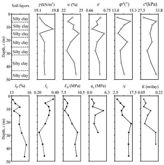
Figure 1.
In situ geotechnical profile and soil properties. Note: γ represents unit weight, w represents water content, e represents the void ratio, φ′ represents effective internal friction angle, c′ represents effective cohesion, IP represents plasticity index, IL represents liquidity index, Es represents compression modulus, qc represents cone resistance in CPT, N represents the blow count of SPT, and Κ represents permeability coefficient.
2.2. Design Scheme and Instrumentation Layout
As shown in Figure 2, the excavation has a diameter of 10.0 m and a final excavation depth of 9.0 m. The supporting piles are 12.0 m in length and composed of H350 and L125 steel. There were a total of 20 supporting piles in the excavation with an interval of 1.56 m between two adjacent piles. Moreover, four walings were installed at elevation levels of 0.0, 3.0, 6.0, and 9.0 m below the ground surface, respectively. In order to improve the impermeability of PRSS, a two-component expansive polymer was grouted behind steel plates [26,36].
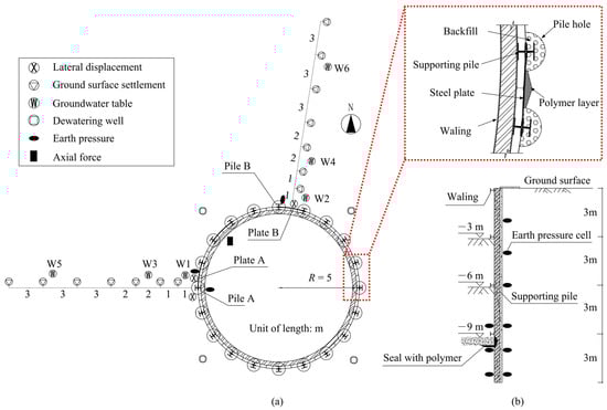
Figure 2.
The excavation retained by PRSS and the monitoring scheme: (a) plane view; (b) cross-section view.
Various instruments were installed to measure the deformations and forces of the PRSS caused by excavation. Inclinometer casings were firmly attached to the supporting piles and the steel plates to monitor their lateral displacements. To monitor the ground surface settlements around the excavation, seven hydrostatic levels were installed behind Pile A and Plate B, respectively. Earth pressure cells were installed on Pile A, Pile B, and Plate A. On the non-excavation side, six soil pressure cells were buried at depths of 2.0 m, 4.0 m, 6.0 m, 8.5 m, 10.0 m, and 11.5 m below the ground surface. On the excavation side, three soil pressure cells were buried at depths of 8.5 m, 10.0 m, and 11.5 m below the ground surface. In order to assess the performance of walings, a pair of sister bar strain gauges were welded on two flanges of each monitored waling to monitor their axial forces. To ensure a dry working face during excavation, four dewatering wells were installed evenly around the perimeter of the excavation at 1.5 m away. Three groundwater observation wells were installed outside the excavation on the west and north sides, respectively.
2.3. Construction Sequence
As shown in Figure 3, the walings and supporting piles are prefabricated in the factory using specialized equipment according to design requirements, and then transported to the site for secondary assembly and installation. The waling is designed as a ring, which requires bending processing of the profile steel to ensure they meet design specifications and assembly accuracy. Plasma cutting is used to create connection holes on the walings and supporting piles according to the design. The supporting piles are assembled from H-section and L-section steels.
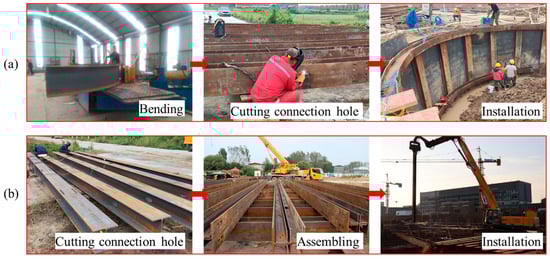
Figure 3.
Prefabrication on the PRSS: (a) waling; (b) supporting piles.
Figure 4 presents the construction sequence of the PRSS. Firstly, following the boring of the pile holes at the designated location, the supporting piles are lifted into the holes and the holes are then backfilled (Figure 4a). After all the supporting piles are installed, the first-level waling is assembled (Figure 4b). Next, a hydraulic pile press machine is used to drive a custom-made sheet pile into the soil along the grooves of the supporting piles to form a slot, and then a steel plate is inserted into the slot (Figure 4c). Subsequently, excavation is carried out to a depth of 3 m below the ground surface, and the second-level waling is installed (Figure 4d). Expansion polyurethane is then grouted behind the steel plates (Figure 4e). These steps (i.e., excavation, installation of waling, and grouting) are repeated to complete the excavation for the second stage (He = 6 m) and the third stage (He = 9 m) (Figure 4f).
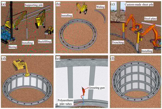
Figure 4.
Construction sequence of the PRSS: (a) installation of supporting piles; (b) installation of first-level waling; (c) installation of steel plates; (d) excavation of soil and installation of second-level waling; (e) grouting behind the steel plates; (f) repeating soil excavation, installation of waling, and grouting until reaching the final depth.
3. Results and Discussion
3.1. Lateral Displacement
3.1.1. Supporting Piles
Figure 5 shows the variations of lateral pile displacements with depth at different excavation stages. After the first stage of excavation, supporting piles deform as a cantilever, with an average lateral displacement of 1.5 mm at the top of supporting piles A and B. This is attributed to the loose connection between the supporting piles and the crown beams caused by installation errors, as well as the absence of preload in crown beams, resulting in insufficient stiffness to restrain inward movement. As the excavation progresses to the deeper levels, lateral pile displacements gradually increase, and their maximum values occur at deeper positions because upper pile movements are constrained by new walings or stiffening of existing walings. It should be noted that at the last excavation stage (He = 9 m), the maximum lateral displacement of supporting piles reaches 9.1 mm, which is far less than the warning value of 18 mm [37]. Supporting piles A and B have a deep inward type of movement, consistent with findings of Clough and O’Rourke [38] and Ou et al. [39]. However, significant movements occur at supporting pile toes, with an average value of 4.9 mm for the two tested piles. It indicates the lack of resistance from the soil beneath the excavation bottom due to shallow embedment depth of the supporting piles.
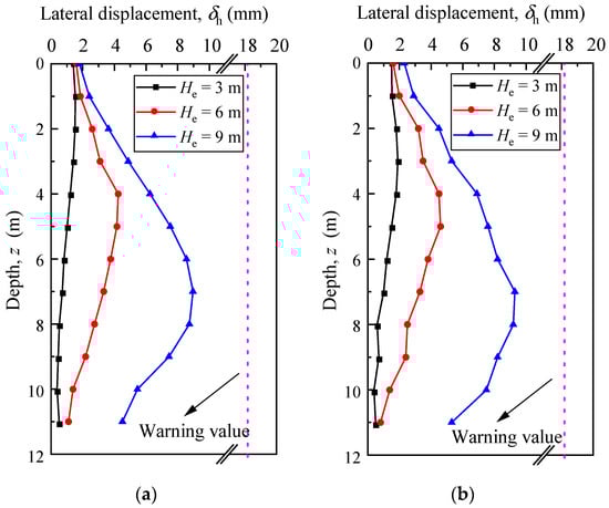
Figure 5.
Lateral displacements of supporting piles: (a) pile A; (b) pile B.
3.1.2. Steel Plates
The lateral displacements of steel plates A and B are illustrated in Figure 6. It is evident from the figure that these displacements increase progressively with excavation depth. Since the steel plates are attached to the supporting piles, they move along with the supporting piles. Consequently, the total displacements of the steel plates equal the sum of the displacements of the supporting piles and the relative displacements of the steel plates with respect to the supporting piles. It can be observed that although the total lateral displacements of the steel plates follow a similar pattern to those of the supporting piles, they are significantly larger. Notably, at the final excavation stage, the average total lateral displacement of steel plates A and B grows to 16.2 mm, approaching the warning value. In terms of the shape of the deformation, the distribution of the relative lateral displacement of the steel plate along the depth is similar to its total lateral displacement. With regard to the magnitude of the deformation, the relative value of the steel plate is approximately half of its total lateral displacement. Additionally, the lateral displacement of the supporting piles is about half of the total lateral displacement of the steel plates.
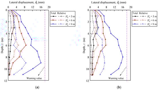
Figure 6.
Lateral displacements of steel plates: (a) plate A; (b) plate B.
Figure 7 shows the relationship between maximum lateral displacement and excavation depth, and the corresponding locations of δhm against He. As illustrated in Figure 7a, the δhm/He ratio for supporting pile ranges from 0.05% to 0.10%, with an average value of 0.07% for supporting pile. For steel plates, the δhm/He ratio ranges from 0.10% to 0.18%, averaging 0.14%. Nevertheless, the average δhm/He ratios for both supporting piles and steel plates in this study are close to those reported for diaphragm walls by Liu et al. [40], but are smaller than those for contiguous pile walls studied by Ni et al. [41] and sheet pile walls investigated by Mana et al. [42]. Furthermore, it can be seen that as excavation progresses, the location of δhm shifts gradually downward. However, for the supporting piles, their maximum lateral displacements occur at a higher level compared to the steel plates, as shown in Figure 7b. The locations of δhm of the supporting piles are near the excavation bottom, whereas for the steel plates, δhm locates at a position that is 1.5 m above the excavation bottom. This difference is mainly due to the higher stiffness of the supporting piles compared to that of the steel plates.
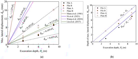
Figure 7.
Variations of maximum lateral displacement: (a) maximum lateral displacement versus excavation depth [36,40,41,42]; (b) maximum lateral displacement depth versus excavation depth.
3.2. Groundwater
Figure 8 shows the variations of the groundwater table during construction. It can be seen that prior to dewatering, the groundwater level was approximately 3.4 m below the ground surface. After dewatering, the groundwater level at 0.5, 3.0, and 11.0 m from the edge of the excavation stabilized at 10.28, 9.27, and 6.18 m below the ground surface, respectively. Site observations revealed that the excavation bottom remained dry throughout the entire excavation process, confirming that the groundwater level consistently stayed below the maximum excavation depth.
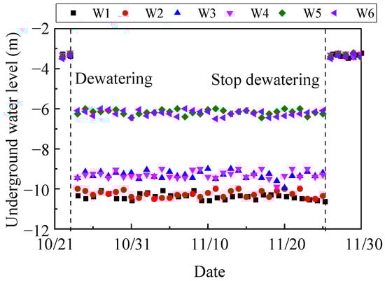
Figure 8.
Variations of underground water level.
In order to verify the impermeability of PRSS, dewatering is halted after the completion of the base slab, and changes in the groundwater level outside the excavation and leakage are monitored. According to Figure 8, after dewatering is stopped, the groundwater table outside the excavation returns to approximately 3.4 m below the ground surface. However, as shown in Figure 9, no obvious water leakage is found inside the excavation. This confirms the efficacy of the supporting structure, comprised of steel plates and grouted polymer, in preventing leakage. Since the waterproofing performance of the PRSS has only been preliminarily validated, further improvements in construction and design, as well as additional model tests, are necessary to enhance this supporting system.
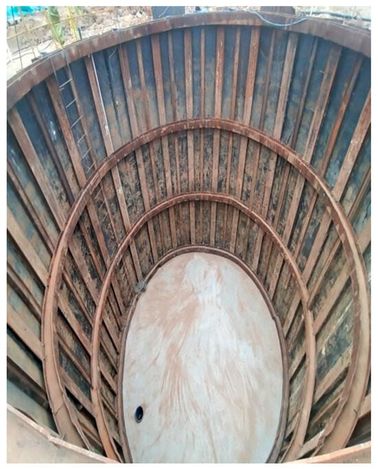
Figure 9.
Interior of the excavation after stopping dewatering.
3.3. Ground Surface Settlement
Figure 10 shows the variations of ground surface settlements behind the supporting piles and the steel plates at different construction stages. It can be seen that prior to excavation, dewatering outside the excavation leads to ground surface settlement, with an average maximum value of 3.0 mm. As excavation progresses, ground surface settlements show an increasing trend, which is more pronounced at a distance of 12 m (1.3 He) from the excavation and diminishes with greater distance. Moreover, the apparent influence range expands with increasing excavation depth. The settlement profile changes from a spandrel type to a concave type, indicating that the location of maximum settlement shifts outward from the excavation edge. The ultimate maximum ground surface settlement behind supporting pile reaches 6.80 mm, representing 0.075% of the excavation depth, occurring at a distance of 2 m (0.22 He) from the excavation edge. On the other hand, there are no significant differences in curve shape, settlement value, affected area, or depth-related changes in ground surface settlement behind steel plates compared to supporting piles. However, the maximum ground surface settlement behind steel plates at the final excavation stage is 7.28 mm, accounting for 0.081% of the excavation depth. Furthermore, throughout the entire excavation process, the maximum ground surface settlement is less than the warning value of 25 mm. In contrast to lateral displacements shown in Figure 3 and Figure 4, it is observed that the differences in ground surface settlement behind steel plates and the supporting piles are not as significant as those in their lateral displacements. The primary reason for this phenomenon is that behind the steel plates, soil arching effects are formed between two adjacent piles, which provide support for the soil outside of them. As a result, the displacement of the soil outside the soil arch is significantly smaller than that of the steel plate.
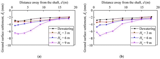
Figure 10.
Ground surface settlement outside the excavation: (a) behind the supporting pile; (b) behind the steel plate.
Figure 11 presents the maximum ground surface settlements (δvm) against the maximum lateral displacements (δhm) of supporting piles and steel plates. As mentioned above, the lateral displacements of steel plates are significantly greater than those of supporting piles, while ground surface settlements behind steel plates appear to be close to those behind supporting piles. Therefore, it can be seen that the δvm/δhm ratio of steel plates is smaller than that of supporting piles. The δvm/δhm ratio of steel plates ranges from 0.4 to 1.2, with an average value of 0.7. For supporting piles, the δvm/δhm ratio ranges from 0.7 to 2.2, averaging 1.2. This findings aligns with Goldberg et al. [43] and Moormann [44], who observed that the δvm/δhm ratio generally falls in the range of 0.5 to 2.0 for excavations in soft ground supported by various retaining systems. Other studies examining the relationship between the movements of retaining walls and ground surface in deep excavations in soft soils [42,45,46] indicate that the δvm/δhm ratios are bounded by the range of 0.5 to 1.0. Ali and Khan [47] reported that the ratio of δvm/δhm generally fell into the range between 0.7 and 1.4 for anchored pile walls in soft to stiff clays. These variations may be attributed to differences in soil conditions, types of retaining walls, and excavation dimensions.
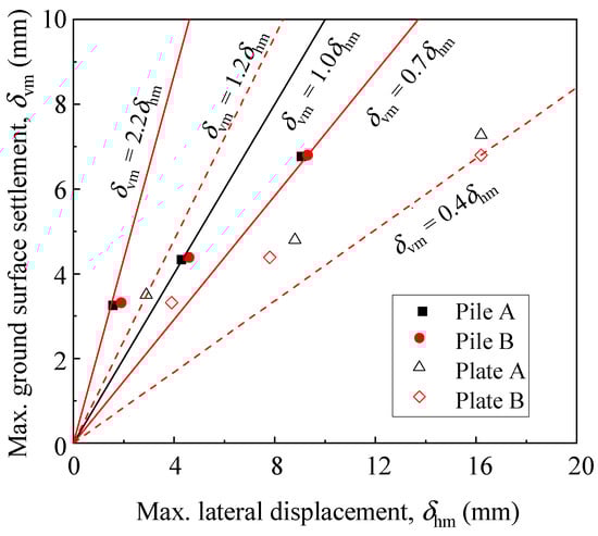
Figure 11.
Relationship between maximum ground settlement and maximum lateral displacement.
3.4. Lateral Earth Pressure
3.4.1. On Supporting Piles
Figure 12 presents the distribution of earth pressure on the supporting piles. It can be observed that before excavation (He = 0 m), the measured earth pressure on the non-excavation side of the supporting piles is lower than the earth pressure at rest (σh0). This shows the impact of supporting pile installation, which induces unloading in the surrounding soil [48]. Although the drilled pile holes are backfilled, they are not consolidated as much as undisturbed soil. In addition, the soil around the borehole exhibits a certain self-stability due to the soil arching effect. This effect, if not disturbed before excavation, partially reduces the lateral earth pressure acting on the supporting piles. When the first soil layer is excavated (He = 3 m), there is a small inward movement on the upper part of the supporting pile. It is widely acknowledged that when a retaining wall moves away from the soil, the soil behind the wall will gradually transition from at an rest state to an active state, resulting in a decrease in earth pressure acting on the wall [49]. Nevertheless, in Figure 10a,b, there is no obvious trend of decreasing earth pressure. This indicates that in practical applications of PRSS, when the movement is small, the earth pressure acting on supporting piles is influenced not only by displacement but also by pile installation. As the excavation deepens (He = 6 m), there is a noticeable decrease in the soil pressure on the supporting piles. At the final excavation stage (He = 9 m), the lateral earth pressure acting on the non-excavation side of the supporting pile continues to decrease. For the upper part of the supporting pile at a depth of 6 m, the earth pressure lies between the active (σha) and at rest (σh0) earth pressure. However, for the lower part of the supporting pile at the same depth, the earth pressure is less than the active earth pressure, even though the lateral pile displacement has not reached the threshold for entering the active state. This phenomenon is due to the soil arching effect formed by circular excavation [50,51,52].
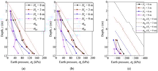
Figure 12.
Lateral earth pressure on supporting piles: (a) non-excavation side of pile A; (b) non-excavation side of pile B; (c) excavation side of pile A.
Figure 12c shows the distribution of lateral earth pressure on the excavation side of supporting pile A, along with theoretical at rest (σh0) and passive (σhp) earth pressures for comparison. It can be found that at the same excavation stage, the earth pressure increases with depth. According to Figure 5 and Figure 12c, although the lateral displacement of the embedded part of the supporting pile increases significantly with excavation depth, reaching a maximum of 7.5 mm, the earth pressure decreases. Throughout the entire construction process, the passive limit state was never reached and the measured earth pressure consistently remained below the passive earth pressure. However, the earth pressure in the passive zone is still moving towards the passive limit state, and the gap between the measured and passive earth pressure is gradually narrowing. This indicates that the excavated soil inside the excavation has a greater influence on reducing the passive soil pressure in the passive zone than the effect of the displacement of the supporting pile towards the excavation. On the other hand, as the lateral displacement of the embedded portion of the supporting piles increases, the soil in the passive zone is gradually compressed, and the soil arching effect of the circular excavation gradually comes into play. This effect enhances the soil’s deformation resistance in the passive zone to some extent.
3.4.2. On Steel Plates
Figure 13 shows the earth pressure distribution on the non-excavation side of steel plate A. It can be observed that prior to excavation (He = 0 m), the earth pressure on the steel plate is significantly less than the earth pressure at rest. Similar to the supporting piles, this is due to the steel plates between piles being inserted after trenching and then backfilled, causing some disturbance to the original soil. Upon completion of the first layer of excavation (He = 3 m), the earth pressure near the bottom of the excavation decreases significantly and is even less than the earth pressure on the supporting piles at the same depth, reflecting the soil arching effect between the piles. However, the change in the earth pressure on the steel plates at greater depths is less pronounced, which is consistent with the lateral displacement trend of the steel plates shown in Figure 6. After completing the second layer of excavation (He = 6 m), there is minimal change in earth pressure above 4 m, whereas the earth pressure below 4 m decreases significantly. Upon completion of the third layer of excavation (He = 9 m), minimal change is observed above 8.5 m, with a decrease in earth pressure below this depth. This indicates an increasing force imbalance between the two sides of the supporting structure with greater excavation depth. Due to the soil arching effect between the two adjacent supporting piles, the steel plates mainly bear the local earth pressure. Consequently, the earth pressure on the steel plates does not vary significantly with increasing excavation depth but remains relatively constant. Given the limited number of soil pressure measurement points in front of the steel plates, the exact horizontal distribution of the soil pressure at specific depths cannot be precisely determined. However, it is evident that the earth pressure acting on the steel plates is lower compared to that on the supporting piles, highlighting the presence of the soil arching effect between the piles.
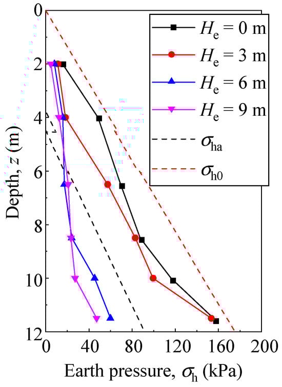
Figure 13.
Lateral earth pressure on the non-excavation side of the steel plates.
3.5. Axial Force of Walings
Figure 14 presents variations of axial forces of walings during the excavation process. The axial forces of walings increase gradually with the excavation depth. At the three excavation stages, the axial forces of the first-level waling are 43.73 kN, 67.07 kN, and 86.64 kN, respectively. According to Figure 5, it can be observed that at the third stage (He = 9 m), the displacements of the supporting piles at their connections with the first-, second-, and third-level walings are 2.1 mm, 5.1 mm, and 8.1 mm, respectively. Consequently, the third-level waling experiences the highest axial force compared to the upper-level walings, due to the largest displacement increment observed at that location under all conditions.
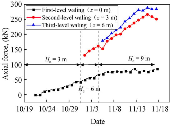
Figure 14.
Variations of axial force of the walings.
4. Conclusions
In this paper, full-scale tests were conducted to verify the performance of PRSS in circular excavation, and the deformation and forces of the PRSS were analyzed. The conclusions drawn from this study are summarized below:
(1) The lateral displacements of both the supporting piles and the steel plates exhibit a convex shape; however, the lateral displacements of the steel plates are significantly greater than those of the supporting piles. The maximum lateral displacement values are 0.10% He for the supporting piles and 0.18% He for the steel plates. The maximum lateral displacements of the supporting piles and steel plates occur above the excavation bottom, at depths of 0.80 He and 0.91 He, respectively.
(2) As excavation depths increase, the ground surface settlement profiles behind both the supporting piles and steel plates transition from a spandrel to a concave shape, with maximum settlement values of 0.075% He and 0.081% He occurring at a distance of 0.22 He from the supporting structure, respectively. The differences in ground surface settlements behind the supporting piles and steel plates are not as obvious as their lateral displacements.
(3) The arching effects caused by the circular excavation result in the earth pressure on the supporting piles being less than the active earth pressure. Moreover, due to the soil arching effect between two adjacent piles, the earth pressure acting on the upper part of the steel plates shows little change with increasing excavation depth, while the soil pressure on the lower part decreases noticeably.
(4) As the excavation depth increases, the supporting piles move toward the inside of the excavation, and the walings gradually provide support for the piles, while the axial force on the walings tends to increase.
Author Contributions
Conceptualization, C.G. and Y.P.; methodology, L.C. and Y.P.; formal analysis, L.C.; investigation, L.C.; resources, C.G.; data curation, L.C.; writing—original draft preparation, L.C.; writing—review and editing, C.G., Y.P. and L.C.; visualization, L.C.; supervision, C.G. and Y.P.; project administration, H.L., Y.P. and M.T.; funding acquisition, C.G., M.T. and H.L. All authors have read and agreed to the published version of the manuscript.
Funding
This research was funded by the Science and Technology Program of Guangzhou Municipal Construction Group Co., Ltd., China, grant number 2022-KJ004. The funder had the following involvement with the study: the construction and monitoring of the PRSS.
Data Availability Statement
The data presented in this study are available on request from the corresponding author due to restrictions on privacy.
Conflicts of Interest
Authors Huqing Liang and Mengxiong Tang were employed by the company Guangzhou Municipal Construction Group Co., Ltd. The remaining authors declare that the research was conducted in the absence of any commercial or financial relationships that could be construed as a potential conflict of interest. The authors declare that this study received funding from the Science and Technology Program of Guangzhou Municipal Construction Group Co., Ltd., China. The funder had the following involvement with the study: the construction and monitoring of the PRSS.
References
- Zhang, C.; Zhang, Y.; Xia, Y.; Fang, H.; Zhao, P.; Wang, C.; Li, B.; Pan, Y.; Zou, Z.; Rabczuk, T.; et al. Risk assessment and optimization of supporting structure for a new recyclable pipe jacking shaft during excavation process. Process Saf. Environ. Prot. 2023, 172, 211–224. [Google Scholar] [CrossRef]
- Zhao, G.; Meng, S.; Guan, C.; Yang, Y. Test Study on the Stress and Deformation Behaviors of a Shaft Supported by a Prefabricated Prestressed Structure. Appl. Sci. 2019, 9, 629. [Google Scholar] [CrossRef]
- Zhang, H.; Wang, H.; Yang, J.; Wang, F. A novel vertical waterproofing joint with trapezoidal steel plate connections for steel–concrete underground silos: Bending test and numerical simulation. Tunn. Undergr. Space Technol. 2023, 137, 105150. [Google Scholar] [CrossRef]
- Xin, J.; Duan, Q.; Jin, K.; Sun, J. A reduced-scale experimental study of dispersion characteristics of hydrogen leakage in an underground parking garage. Int. J. Hydrogen Energy 2023, 48, 16936–16948. [Google Scholar] [CrossRef]
- Rapti, D.; Tinti, F.; Caputo, C.A. Integrated Underground Analyses as a Key for Seasonal Heat Storage and Smart Urban Areas. Energies 2024, 17, 2533. [Google Scholar] [CrossRef]
- Liu, B.; Zhang, D.; Wang, Y.; Wang, N.; Xu, W. Design optimization and observed performance of a super-large foundation pit excavation subjected to unsymmetrical loading in water-rich floodplain: A case study. Soils Found. 2023, 63, 101329. [Google Scholar] [CrossRef]
- Nejjar, K.; Dias, D.; Cuira, F.; Chapron, G.; Le Bissonnais, H. Numerical modelling of a 32 m deep excavation in the suburbs of Paris. Eng. Struct. 2022, 268, 114727. [Google Scholar] [CrossRef]
- Lu, T.; Wu, K.; Liu, S.; Cai, G. Method for estimating three-dimensional effects on braced excavation in clay. Tunn. Undergr. Space Technol. 2023, 141, 105355. [Google Scholar] [CrossRef]
- Mishra, A.; Sawant, V.A. A Detailed Investigation on Contiguous Pile Wall with Homogeneous Backfill. Geotech. Geol. Eng. 2023, 41, 2065–2089. [Google Scholar] [CrossRef]
- Ramadan, M.I.; Meguid, M. Behavior of cantilever secant pile wall supporting excavation in sandy soil considering pile-pile interaction. Arab. J. Geosci. 2020, 13, 466. [Google Scholar] [CrossRef]
- Zolqadr, E.; Yasrobi, S.S.; Norouz Olyaei, M. Analysis of soil nail walls performance-Case study. Geomech. Geoengin. Int. J. 2016, 11, 1–12. [Google Scholar] [CrossRef]
- Liu, L.; Wu, R.; Congress, S.S.C.; Du, Q.; Cai, G.; Li, Z. Design optimization of the soil nail wall-retaining pile-anchor cable supporting system in a large-scale deep foundation pit. Acta Geotech. 2021, 16, 2251–2274. [Google Scholar] [CrossRef]
- Shao, Y.; Macari, E.J.; Weiming, C. Compound deep soil mixing columns for retaining structures in excavations. J. Geotech. Geoenviron. Eng. 2005, 131, 1370–1377. [Google Scholar] [CrossRef]
- Nishanthan, R.; Liyanapathirana, D.S.; Leo, C.J. Deep Cement Mixed Walls with Steel Inclusions for Excavation Support. Geotech. Geol. Eng. 2018, 36, 3375–3389. [Google Scholar] [CrossRef]
- Waichita, S.; Jongpradist, P.; Patawanit, P.; Jamsawang, P.; Arangelovski, G.; Likitlersuang, S. Deformation and failure mechanism of deep cement mixing walls: Experimental study using physical model tests. Arch. Civ. Mech. Eng. 2021, 21, 127. [Google Scholar] [CrossRef]
- Tan, Y.; Paikowsky, S.G. Performance of Sheet Pile Wall in Peat. J. Geotech. Geoenviron. Eng. 2008, 134, 445–458. [Google Scholar] [CrossRef][Green Version]
- Caputo, G.V.; Conti, R.; Viggiani, G.M.B.; Prüm, C. Improved Method for the Seismic Design of Anchored Steel Sheet Pile Walls. J. Geotech. Geoenviron. Eng. 2021, 147, 4020154. [Google Scholar] [CrossRef]
- Sobala, D.; Rybak, J. Steel Sheet Piles-Applications and Elementary Design Issues. IOP Conf. Ser. Mater. Sci. Eng. 2017, 245, 22072. [Google Scholar] [CrossRef]
- Lu, W.; Lou, J.; Webster, C.; Xue, F.; Bao, Z.; Chi, B. Estimating construction waste generation in the Greater Bay Area, China using machine learning. Waste Manag. 2021, 134, 78–88. [Google Scholar] [CrossRef]
- Yücel, M.; Kayabekir, A.E.; Bekdaş, G.; Nigdeli, S.M.; Kim, S.; Geem, Z.W. Adaptive-Hybrid Harmony Search Algorithm for Multi-Constrained Optimum Eco-Design of Reinforced Concrete Retaining Walls. Sustainability 2021, 13, 1639. [Google Scholar] [CrossRef]
- Seol, Y.; Lee, S.; Lee, J.; Han, J.; Hong, G. Excavation Method Determination of Earth-Retaining Wall for Sustainable Environment and Economy: Life Cycle Assessment Based on Construction Cases in Korea. Sustainability 2021, 13, 2974. [Google Scholar] [CrossRef]
- Wasim, M.; Vaz Serra, P.; Ngo, T.D. Design for manufacturing and assembly for sustainable, quick and cost-effective prefabricated construction—A review. Int. J. Constr. Manag. 2022, 22, 3014–3022. [Google Scholar] [CrossRef]
- Wang, W.; Ding, W.; Yang, X.; Zheng, G.; Xu, Z. Deep excavation engineering and underground engineering—New techniques of high-efficiency and energy-saving, low environmental impact, and sustainable development. China Civ. Eng. J. 2020, 53, 78–98. [Google Scholar] [CrossRef]
- Guo, C.; Ye, J.; Zhao, C.; Wang, F. Mechanical and deformation characteristics of composite assembled supporting structure. Geotech. Res. 2020, 7, 230–243. [Google Scholar] [CrossRef]
- Guo, C.; Wang, R.; Lin, P.; Wang, F. Numerical analyses of a prefabricated retaining system for foundation pits in silt soils. Geotech. Res. 2020, 7, 173–190. [Google Scholar] [CrossRef]
- Pan, Y.; Fang, H.; Li, B.; Wang, F. Stability analysis and full-scale test of a new recyclable supporting structure for underground ecological granaries. Eng. Struct. 2019, 192, 205–219. [Google Scholar] [CrossRef]
- Guan, C.; Yang, Y.; Wang, C. Rapid excavation with a newly developed retaining system: Spiral assembly steel structure. J. Cent. South Univ. 2015, 22, 2719–2729. [Google Scholar] [CrossRef]
- Zhang, C.; Zhai, W.; Xia, Y.; Wang, C.; Zhao, P.; Li, B.; Pan, Y.; Fang, H.; Ummin, O.; He, W.; et al. Analysis of the stability of a novel assembled working shaft support structure during pipe jacking construction: Experiments and numerical simulations. Eng. Fail. Anal. 2024, 162, 108418. [Google Scholar] [CrossRef]
- Kim, K.; Lee, D.; Cho, J.; Jeong, S.; Lee, S. The effect of arching pressure on a vertical circular shaft. Tunn. Undergr. Space Technol. 2013, 37, 10–21. [Google Scholar] [CrossRef]
- Tran, V.D.H.; Meguid, M.A.; Chouinard, L.E. Discrete Element and Experimental Investigations of the Earth Pressure Distribution on Cylindrical Shafts. Int. J. Geomech. 2014, 14, 80–91. [Google Scholar] [CrossRef]
- Tangjarusritaratorn, T.; Miyazaki, Y.; Sawamura, Y.; Kishida, K.; Kimura, M. Numerical investigation on arching effect surrounding deep cylindrical shaft during excavation process. Undergr. Space 2022, 7, 944–965. [Google Scholar] [CrossRef]
- Xiong, G.J.; Wang, J.H.; Chen, J.J. Theory and practical calculation method for axisymmetric active earth pressure based on the characteristics method considering the compatibility condition. Appl. Math. Model. 2019, 68, 563–582. [Google Scholar] [CrossRef]
- Tobar, T.; Meguid, M.A. Experimental Study of the Earth Pressure Distribution on Cylindrical Shafts. J. Geotech. Geoenviron. Eng. 2011, 137, 1121–1125. [Google Scholar] [CrossRef]
- Tan, Y.; Wang, D. Characteristics of A Large-Scale Deep Foundation Pit Excavated by Central-Island Technique in Shanghai Soft Clay. Part II: Top-Down Construction of the Peripheral Rectangular Pit. J. Geotech. Geoenviron. Eng. 2013, 139, 1894–1910. [Google Scholar] [CrossRef]
- Qiao, Y.; Xie, F.; Bai, Z.; Lu, J.; Ding, W. Deformation characteristics of ultra-deep circular shaft in soft soil: A case study. Undergr. Space 2024, 16, 239–260. [Google Scholar] [CrossRef]
- Wang, F.; Chen, L.; Pan, Y.; Guo, C.; Guo, C.; Yue, L.; Chu, X. Deformation characteristics of excavation supported by prefabricated recyclable structures. Proc. Inst. Civ. Eng. Geotech. Eng. 2024, 1–43. [Google Scholar] [CrossRef]
- GB 50497-2019; Technical Standard for Monitoring of Building Excavation Engineering. Ministry of Housing and Urban-Rural Development: Beijing, China, 2019.
- Clough, G.W.; O’Rourke, T.D. Construction induced movements of in situ walls. In Proceedings of the ASCE Conference on Design and Performance of Earth Retaining Structures, New York, NY, USA, 18–21 June 1990; pp. 439–479. [Google Scholar]
- Ou, C.; Liao, J.; Lin, H. Performance of Diaphragm Wall Constructed Using Top-Down Method. J. Geotech. Geoenviron. Eng. 1998, 124, 798–808. [Google Scholar] [CrossRef]
- Liu, M.; Zhang, D.; Fang, Q.; Hou, Y. Wall and Ground Movements due to Deep Excavation of Tianjin Subway Station. DEStech Trans. Mater. Sci. Eng. 2017, 2017, 9944. [Google Scholar] [CrossRef] [PubMed][Green Version]
- Ni, X.; Lu, J.; Wang, Y.; Shi, J.; Chen, W.; Tang, L. Field investigation of the influence of basement excavation and dewatering on ground and structure responses. Tunn. Undergr. Space Technol. 2021, 117, 104121. [Google Scholar] [CrossRef]
- Mana, A.I.; Clough, G.W. Prediction of Movements for Braced Cuts in Clay. J. Geotech. Eng. Div. 1981, 107, 759–777. [Google Scholar] [CrossRef]
- Goldberg, D.T.; Jaworski, W.E.; Gordon, M.D. Lateral Support Systems and Underpinning; Federal Highway Administration: Washington, DC, USA, 1976. [Google Scholar]
- Moormann, C. Analysis of Wall and Ground Movements Due to Deep Excavations in Soft Soil Based on a New Worldwide Database. Soils Found. 2004, 44, 87–98. [Google Scholar] [CrossRef]
- Ou, C.; Hsieh, P.; Chiou, D. Characteristics of ground surface settlement during excavation. Can. Geotech. J. 1993, 30, 758–767. [Google Scholar] [CrossRef]
- Hsieh, P.; Ou, C. Shape of ground surface settlement profiles caused by excavation. Can. Geotech. J. 1998, 35, 1004–1017. [Google Scholar] [CrossRef]
- Ali, J.; Khan, A.Q. Behaviour of anchored pile wall excavations in clays. Proc. Inst. Civ. Eng. Geotech. Eng. 2017, 170, 493–502. [Google Scholar] [CrossRef]
- Richards, D.J.; Clark, J.; Powrie, W. Installation effects of a bored pile wall in overconsolidated clay. Géotechnique 2006, 56, 411–425. [Google Scholar] [CrossRef]
- Terzaghi, K. Theoretical Soil Mechanics; John Wiley and Sons, Inc.: New York, NY, USA, 1943; p. 510. [Google Scholar]
- Guojun, X.; Jianhua, W. A rigorous characteristic line theory for axisymmetric problems and its application in circular excavations. Acta Geotech. 2020, 15, 439–453. [Google Scholar] [CrossRef]
- Liu, F.Q.; Wang, J.H. A generalized slip line solution to the active earth pressure on circular retaining walls. Comput. Geotech. 2008, 35, 155–164. [Google Scholar] [CrossRef]
- Liu, F.Q.; Wang, J.H.; Zhang, L.L. Axi-symmetric active earth pressure obtained by the slip line method with a general tangential stress coefficient. Comput. Geotech. 2009, 36, 352–358. [Google Scholar] [CrossRef]


Disclaimer/Publisher’s Note: The statements, opinions and data contained in all publications are solely those of the individual author(s) and contributor(s) and not of MDPI and/or the editor(s). MDPI and/or the editor(s) disclaim responsibility for any injury to people or property resulting from any ideas, methods, instructions or products referred to in the content. |
© 2024 by the authors. Licensee MDPI, Basel, Switzerland. This article is an open access article distributed under the terms and conditions of the Creative Commons Attribution (CC BY) license (https://creativecommons.org/licenses/by/4.0/).