Abstract
The sudden collapse of a school roof in the UK brought widespread attention to the structural integrity of buildings constructed with reinforced autoclaved aerated concrete (RAAC), a material widely used from the 1950s to the mid-1990s. RAAC, known for its lightweight and insulating properties, has been found to suffer from weak compressive strength, poor reinforcement anchorage, and high susceptibility to environmental degradation. The structural profiles of RAAC panels in the UK are unique, particularly in their reinforcement configurations and failure modes, which limits the applicability of the existing literature from other regions. This paper conducts a state-of-the-art review, identifying a significant gap in current research due to the unique challenges posed by RAAC in the UK, and highlights the need for novel methodologies. In response to this gap, the paper introduces a multi-criteria decision analysis (MCDA) framework utilising the decision-making trial and evaluation laboratory (DEMATEL) method to assess the interdependencies of RAAC defects. This methodology quantifies the influence of observed defects and guides the selection of appropriate remediation strategies, offering a more structured and objective approach to RAAC panel assessment and retrofitting. Practically, this study aligns with ongoing research efforts towards the digitalisation of RAAC management by integrating the MCDA model within digital asset management systems. This integration supports a holistic approach to addressing the RAAC crisis, enhancing current efforts to digitalise the surveying and management processes and ensuring safer long-term solutions.
1. Introduction
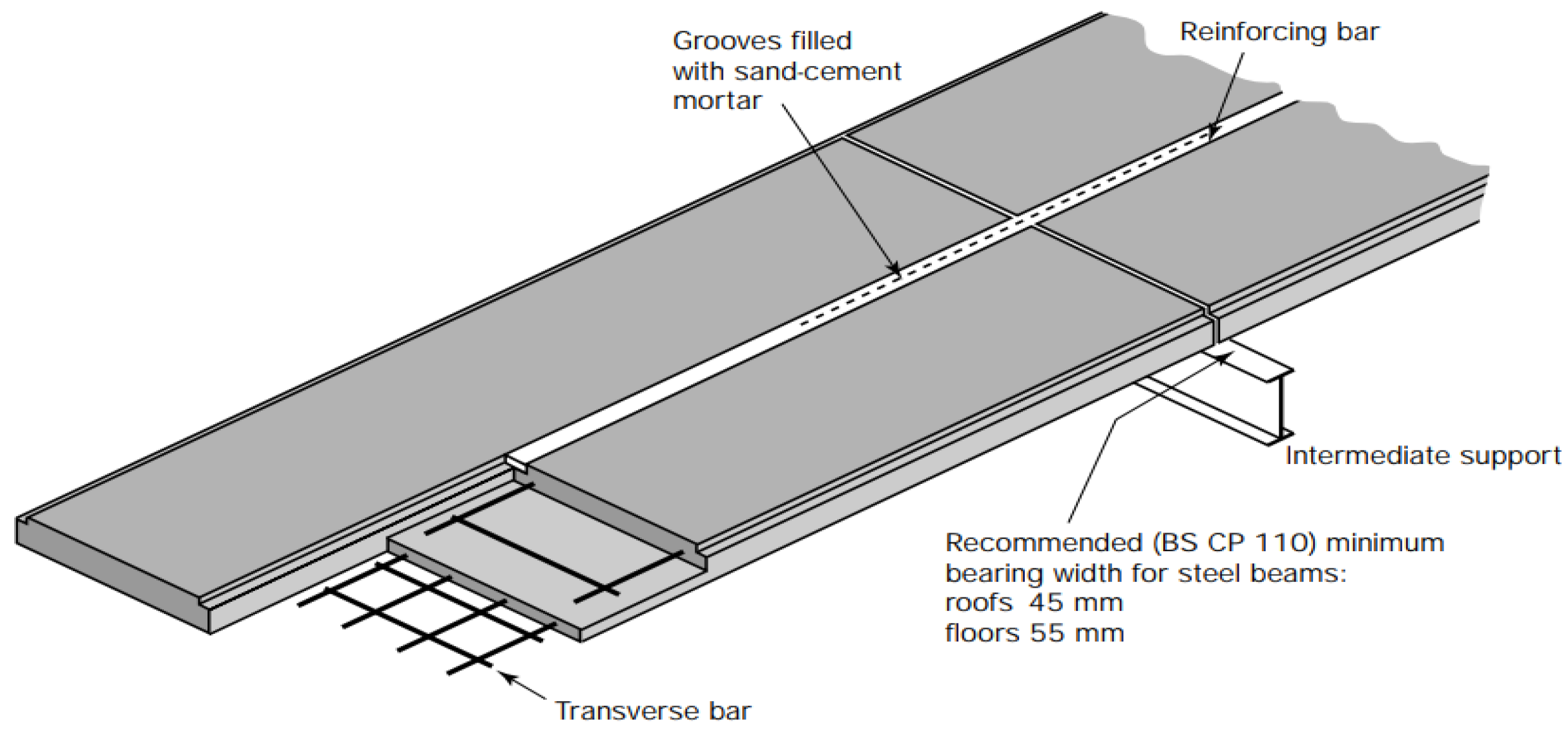
In the 1950s–1990s, reinforced autoclaved aerated concrete (RAAC) was heavily used in the UK as a lightweight construction material suitable for mass production in prefabricated roof, floor, and wall components [1,2]. In 2018, the collapse of a school roof made of RAAC panels initiated a blanket effect necessitating the inspection of the safety of all RAAC buildings in the UK. The safety concerns regarding RAAC performance originated in 1996 when the Building Research Establishment (BRE) noted that RAAC panels are reaching their end of service life with demonstrations of structural degradations. The BRE demonstrated this in the publication of information paper IP 10/96 (1996) [1], showing the results of a series of tests on panels constructed in the years 1991 and 1995. These tests mainly involved material analysis, as well as cyclic loading and strength testing, to understand the failure mechanism of panels with the typical reinforcement arrangements depicted in Figure 1.
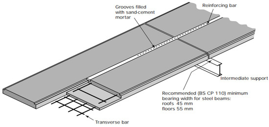
Figure 1.
Typical RAAC panel reinforcement arrangement [1].
In principle, the manufacture of RAAC imposes certain phenomena not common to standard concrete. For instance, the BRE cites the shadow effect as an attribute of RAAC panels [2]. The shadow effect is defined as a feature specific to RAAC components developed during the AAC foaming process as gas bubbles tend to collect and merge in the area above the reinforcement. The physical manifestation appears as voids shadowing rebars in vicinity. The voidage generally aligns with the plane that was vertical during the casting process, which, for panels cast on their side, means that these void zones often run horizontally through the panel at the level of the reinforcement. As such, it is believed that the shadow effect may be minimised by using smaller rebar diameters. However, a counter complication may arise whereby the larger AAC matrix predominantly absorbs the corrosion products and hence limits any visible cracking on the panel, contributing to the observed sudden shear collapse effect. The most common failure mechanisms are summarised in relation to their causes and possible control measures in Table 1.

Table 1.
Common failure mechanisms associated with RAAC panels [2].
An elaboration of the stage by which the most common degradation mechanisms appear is displayed in a Venn diagram in Figure 2. In establishing this information, newly built RAAC structures may be better equipped to control a predicted defect.
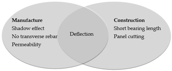
Figure 2.
Venn diagram of stages in which common RAAC defects originate.
As the manufacturer of problematic RAAC panels is not precisely identifiable, current surveying trends may also infer correlations between different panels in relation to shared mechanisms hinting at shared manufacturing origins.
In Europe, the specific composition of the mixtures employed by individual producers are unique in terms of the used materials and manufacturing procedures [3]. Similarly, the exact material composition of these problematic RAAC panels is not entirely discernible. In response to the 2018 collapse incident, the Institution of Structural Engineers (IStructE) in the UK produced a guidance detailing the identification, inspection, retrofitting, and management of RAAC structures [4]. Amidst the wide scarcity of literature on RAAC [5,6], the IStructE RAAC guidance serves as the rulebook for intervention measures to control the RAAC crisis.
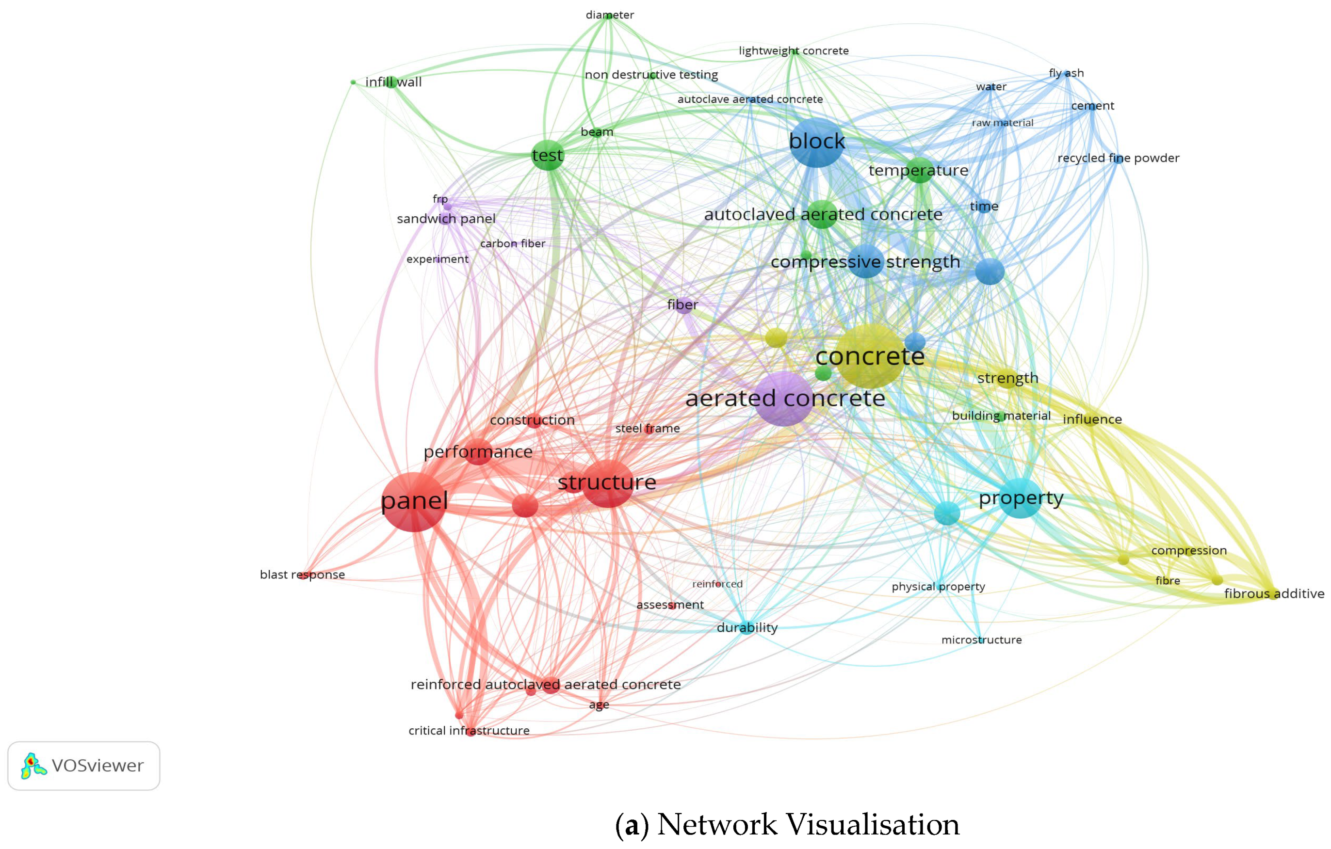
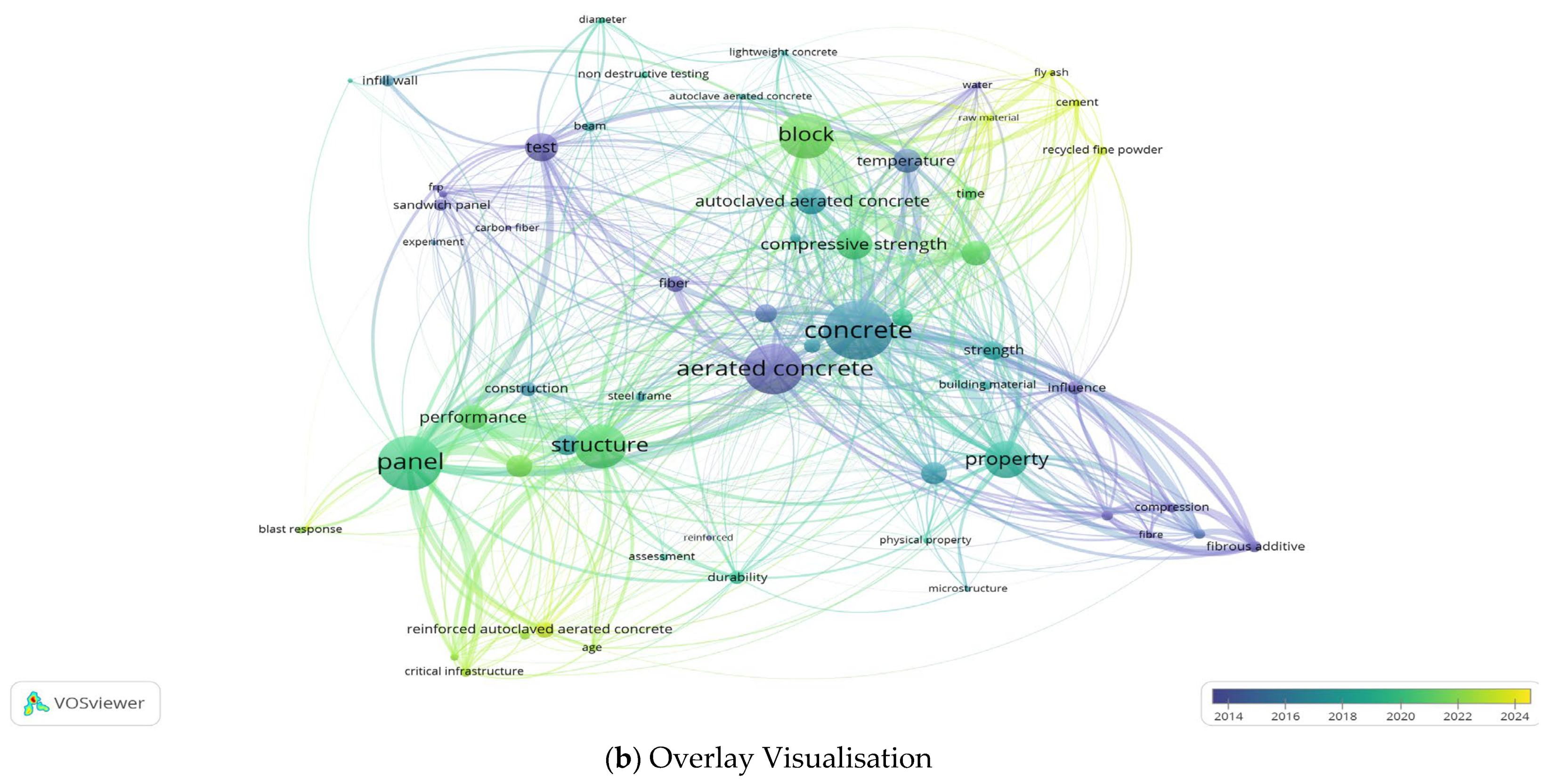
In an overview of the existing literature on RAAC, the visualisation in Figure 3 illustrates the association strength between closely related keywords. The red cluster focuses on the structural application and performance of RAAC, particularly in building and panel systems, highlighting research on structural behaviour, blast response, and more. The green cluster emphasises testing methodologies and structural evaluation of aerated concrete. The blue cluster examines the fundamental properties of AAC, such as compressive strength, with an emphasis on the role of blocks and related material properties. The yellow cluster explores the enhancement of material properties, particularly using fibrous additives. Finally, the purple cluster connects to reinforcement techniques and specific applications like sandwich panels. Notably, the weak connections between RAAC in the red cluster and other topics underscore the scarcity of literature on this subject. The overlay visualisation further demonstrates this through the recency of RAAC literature highlighted in yellow.
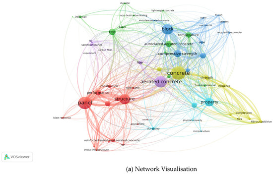
Figure 3.
Keyword data network of recent research related to RAAC showing: (a) network visualisation and (b) overlay visualisation, mapped by association strength using VOSviewer.
In principle, it is necessary to establish the differences between standard concrete and AAC or aircrete to reflect the distinctive properties and structural behaviour. AAC is a lightweight siliceous material consisting of an aerated cellular structure produced from a reaction between calcareous and siliceous materials bonded by calcium silicate hydrates. The mixed slurry is poured into a steel mould before autoclave curing precedes binder setting for the RAAC to be ready for application. RAAC is therefore a lightweight porous material with excellent insulation capacity but suffers form low alkalinity and hence poor a reinforcement bond in comparison with standard concrete [2,3,7]. Due to its high deformability, afforded by the low density lending to reduced inertial forces, RAAC is proven to have excellent seismic capacity, with its low stiffness allow for high ductility but subsequent ductile failure under exposure to dynamic loads [2]. A summary of the ranges of the typical mechanical property values of RAAC panels is displayed in Table 2.
Table 2.
Typical value ranges of mechanical properties of RAAC panels.
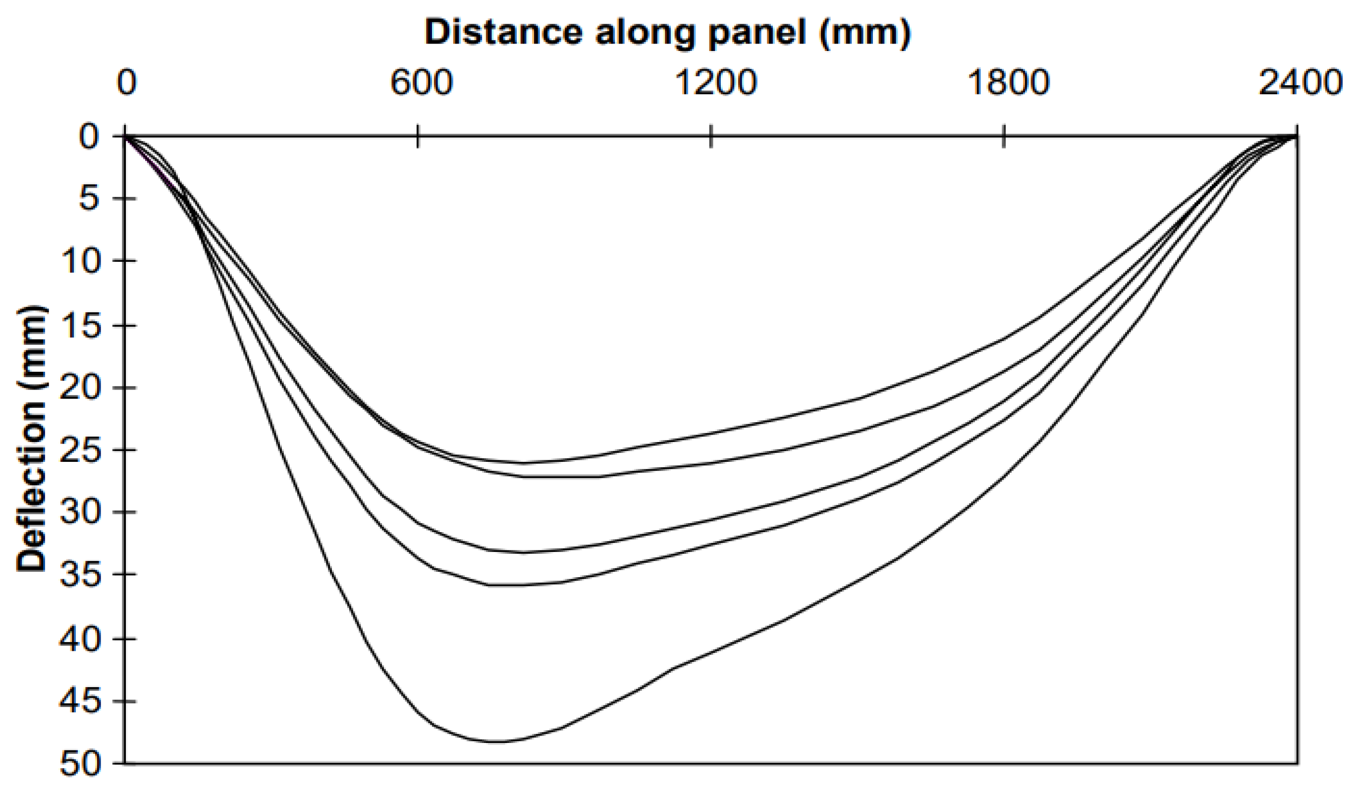
As an aerated mixture with high porosity, the moisture content of RAAC is highly critical, with reduced moisture leading to improved mechanical properties [2]; hence, the cellular microstructure is extremely vulnerable to degradation in humid or wet environments. The moisture content has been observed to affect the elastic modulus, and when reaching saturation can lead to a decrease of up to 20% in the elastic modulus of AAC [2]. Although AAC is highly water-absorbent, in cases of poor rebar anchorage, penetrated water may circumvent the cementitious matrix and directly instigate corrosion. AAC also has poor alkalinity and subsequent bond characteristics; therefore, the steel reinforcement is often coated with bitumen or cementitious latex to enhance its anchorage. However, according to the BRE, there have been cases of poor anchorage between the rebar and the coating material. In acknowledgment of poor bond characteristics, a transverse anchorage reinforcement is welded to the longitudinal rebars at the end near the supports to control deflections arising from slippage. In the event of rebar corrosion, the typical outward expansion of concrete may not be observed in RAAC given the poor anchorage, making any collapse imminent, with no signs of cracking or spalling. This phenomenon is especially prevalent where transverse reinforcement is lacking in RAAC panels. In the 1995 series of BRE tests on RAAC panels, it was established that, by default, operational loads are carried by the reaction forces, and in the event of excessive deflections where rebar slippage may occur, the role of transverse rebars is to carry the ultimate load. In the second series of the BRE 1995 tests, in this mechanism, depicted in Figure 4, high deflections were concentrated when transverse reinforcement at the end supports was lacking. Identical panels were selected for testing in the second series to represent standard RAAC panels, measuring 2400 mm long, 600 mm wide, and 1000 mm deep. The panels are reinforced with a layer of 8 mm diameter longitudinal bars and 6 mm diameter transverse bars at the bottom for an applied load of 2.1 kN/m2 in addition to self-weight. This standard panel profile allows for an estimation of a standardised deflection that explains the dual importance of ensuring adequate bond strength and securing a transverse anchorage reinforcement in RAAC panels.
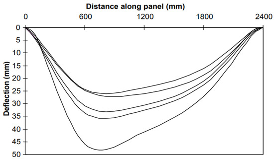
Figure 4.
Deflection of RAAC panels under ultimate load in second series of 1995 tests [2].
In reinforcing AAC, it is argued that due to its brittle and highly porous nature with non-autoclaved aerated concrete, the use of fibre reinforcement may yield similar ductility performance to that of fibre-reinforced aerated concrete (FRAC), mainly due to the act of bridging micro- and macro-cracks [8]. The tensile stress–strain response of unreinforced AAC was compared with polymeric fibres in FRAC, demonstrating the effect of fibre bridging in the form of increased tensile strain in FRAC compared with that in AAC. However, the compressive strength of AAC exceeded that of FRAC by more than 50%, and this was attributed to the omittance of autoclaving in the FRAC samples to maintain fibre integrity. However, it must be noted that fly ash was used in the FRAC samples; therefore, we naturally expected to observe pozzolanic reactions that may have hindered the early-age hydration and compressive strength development observed in AAC when solely using cement as a binder. On the other hand, the flexural toughness of FRAC was more than 100 times greater than that of AAC. However, it must be noted that this experiment did not introduce a reinforcement in the AAC samples; therefore, it remains difficult to directly endorse the use of FRAC over AAC in its unreinforced form. In addressing this disparity, another paper aims to utilise cement and limestone as a binder of AAC reinforced with different fibre materials to establish the structural performance of fibre-reinforced autoclaved aerated concrete (FRAAC) [6]. The authors protect the fragile fibres during autoclaving by hydrophilizing the fibres through soaking them in an aqueous solution of sulfonol before filtering and adding them to the mixture. The main findings included higher compressive and flexural strengths achieved when using hydrophilized carbon fibres in FRAAC compared with non-hydrophilized samples. In addition to the protection afforded by hydrophilization, the different fibres used (i.e.,: carbon, polypropene, basalt, and kaolin) were tested for resistance against the high alkalinity of concrete (pH of 12.6–13.1) and high temperature of the autoclaving process at 180 °C. The microstructural analysis of FRAAC showed that unlike the other fibres used, the non-hydrophilized carbon fibres bonded mechanically, not chemically, with the concrete matrix, and exhibited pull-out during breakage. This resulted in close contact between the fibre–concrete interface without spalling. Hydrophilized carbon fibres exhibit a similar pull-out mechanism with slight differences in the interface contact microstructure. In a review article published to study the physical and mechanical of AAC, it was demonstrated that the key to achieving a durable AAC mix design lies in controlling the anisotropy of pore distribution [5], suggesting that, contrary to the case for the use of standard longitudinal and transverse rebars, it is essential to utilise additives such as fibres and nano-particles enhancing matrix continuity.
Ultimately, the scarcity of research papers on AAC highlight a noticeable gap in the literature, particularly regarding the use of fibrous additives in porous concretes, specifically AAC [6]. As such, the existing literature mainly aims to infer the performance of AAC by comparing it with a baseline understanding of general non-autoclaved aerated concrete mixtures [3,6,7]. This indicates an important gap to be filled with experimental research aiming to establish the baseline performance of RAAC as a structural material.
2. Structural Assessment and Retrofitting
This chapter divides the structural assessment and retrofitting of RAAC into two distinct approaches: traditional assessment and digitalised assessment. The traditional assessment explains the protocols of surveying, remediation, and management of RAAC structures according to the IStructE guidance [4], whereas the digitalised assessment aims to upgrade this approach with specific advancements in the protocols entailed. The digitalised assessment is expanded upon with an original methodology utilising multi-criteria decision analysis (MCDA) tools to produce a coherent basis for RAAC assessment and remediation.
2.1. Traditional Assessment
According to the RAAC identification guidance produced by the Department for Education (DfE), the typical RAAC panel consists of distinguishing features such as a width of 600 mm and with lengths up to 6 m and a chamfer at each end [9]. Once RAAC is confirmed present, a structural assessment ensues to determine the risk category to which a given panel conforms. The risk categories are divided into high-risk, necessitating immediate remediation; medium-risk, necessitating annual surveying; and low-risk, requiring periodic surveying every 5 years. The only condition that is considered an exception that may raise a panel’s risk level is whether water damage is suspected. Water ingress has been documented to greatly reduce the mechanical properties of AAC while contributing to corrosion and debonding, hence the classification of water damage as a high-risk event. In most applications, RAAC panels are laid flat in roofs, which dramatically increases the probability of water exposure and therefore all the associated pernicious effects. Nonetheless, the subsequent recommendation for immediate remediation hints at the need to classify water-related degradation accurately to ascertain that it has occurred to a quantifiable degree.
The main issues encountered in RAAC panels may be divided into two categories: panel defects and reinforcement defects. Panel defects are mostly screened with NDT methods targeting issues such as cracking, spalling, waterproof membrane damage, and high deflections. Reinforcement defects are assessed with a combination of NDT methods and destructive testing to confirm the availability of transverse reinforcement and adequate end bearing conditions. A summary of the currently identified risk factors targeted in inspections is displayed in Table 3.
Table 3.
IStructE guidance on high-risk conditions under water damage [4].
According to the IStructE guidance, the failure mode associated with missing transverse reinforcement is presently a subject of academic research. In an experiment conducted to study the post-elastic response of aircrete and explore parameters for estimating deflection [3], the failure at ultimate load was reported to occur primarily at the side of the deficient anchorage bars. In the 1995 series of laboratory studies conducted by the BRE, the deflection observed in relation to the maximum load sustained by a given RAAC panel took the shape of a beam nonuniformly loaded at one end. For simplicity, the failure mode can be described with first principles, where the deflection is concentrated in the edge due to shortfalls in bearing length and transverse reinforcement. This may be an important observation in relation to the assessment stage where an RAAC panel may be sagging at one end to produce a gap with the adjacent panel. Although this deflection (greater than 20 mm) is considered a critical risk, it is not clearly attributed to any given phenomenon. In the BRE test series, near-support deflections were attributed to the location and condition of transverse rebar. Given the insights derivable from such studies, it is imperative that other independent case studies are reviewed to identify possibly overlooked defects, as shown in Table 4.
Table 4.
UK case studies and experiments on RAAC structures [3].
The fragile nature of RAAC entails the need for a non-intrusive inspection survey whereby the previously outlined concerns can be assessed safely. By default, NDT takes precedence in screening for absent transverse reinforcement or in evaluating deflection in RAAC panels. The reinforcement condition is tested for the availability of transverse reinforcement by utilising covermeters and radar scanning to ensure longitudinal rebar continuity over end bearings. However, there are limitations associated with the reliability of these methods, with variables such as panel thickness interfering with scanning. Moreover, as seen in Table 2, in a case study of RAAC roof panels built in the early 1970s, visible longitudinal bars were observed near supports, which led to the incorrect assumption that a sufficient number of bars existed throughout the panel’s span [3]. This is an especially crucial observation given that the IStructE guidelines mainly concern the inspection of end bearings and subsequent transverse reinforcement without sufficient regard to midspan rebar continuity. As such, drilling is also used to ascertain bearing length and reinforcement conditions. Naturally, such intrusive surveys may compromise the fragile structural integrity of RAAC panels. Additionally, intrusive surveys increase the risk of encountering the presence of asbestos within RAAC panels or surface coverings, which has been well documented [10].
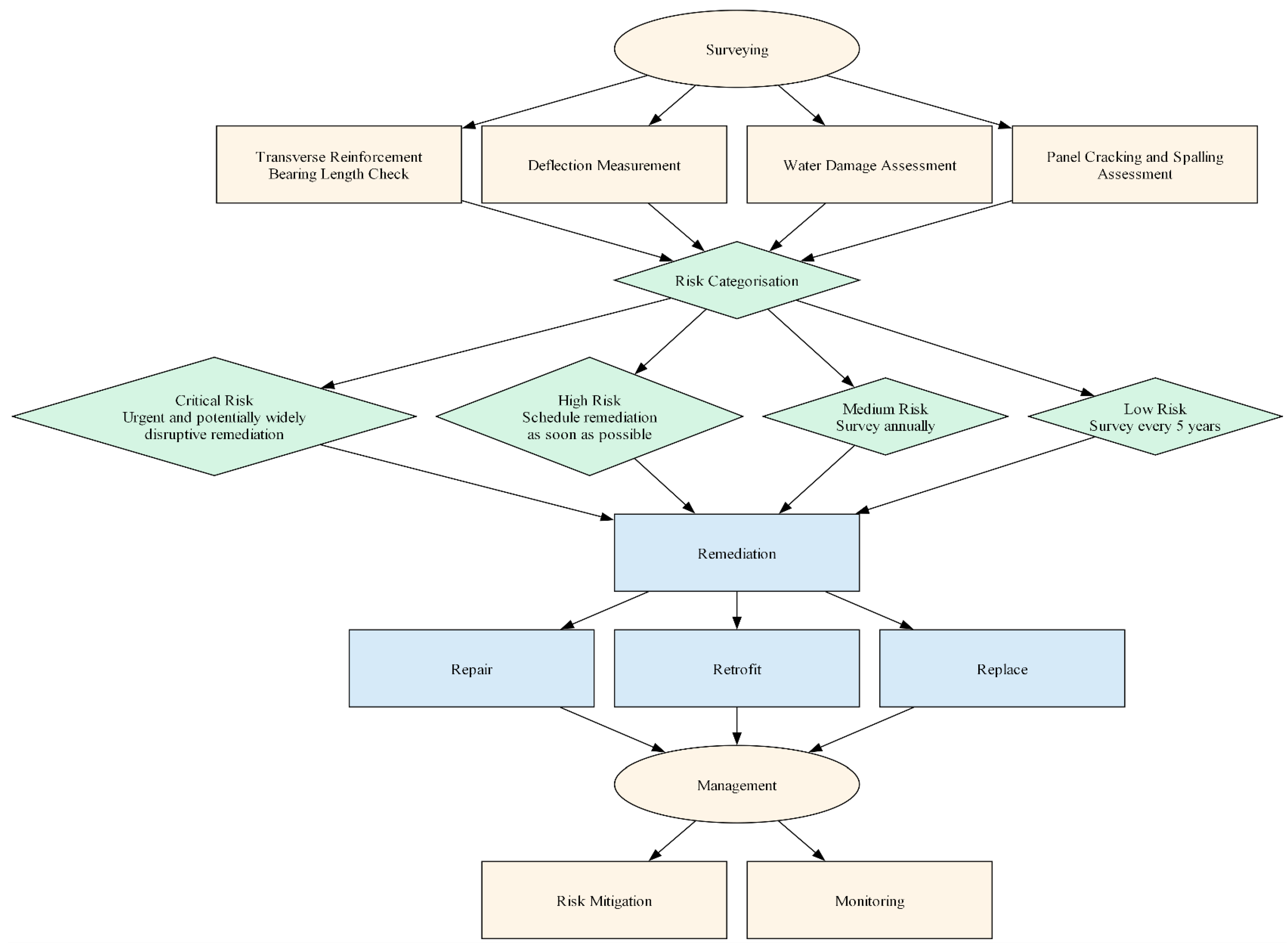
In assessing deflection, the IStuctE guidance recommends that at least 10% of panels are selected strategically as representative samples according to their location and condition. A laser level is utilised to record panel deflection values to either recommend remediation or serve as baseline measurements for future investigations. A non-exhaustive summary of the surveying process is illustrated in the flowchart in Figure 5. Evidently, this process is cost-, time-, and labour-intensive with considerable risks of human error in judgment.
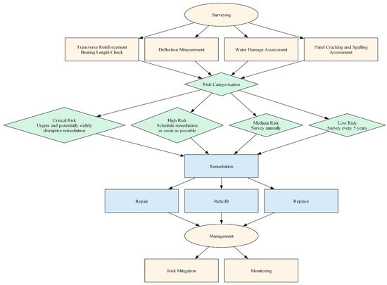
Figure 5.
Current RAAC inspection, remediation, and management process [4].
In surveying for signs of water damage, cracking and spalling are the main targets of observations. However, there is no specific method adopted for assessing water damage. The effects water damage revealed in the 1981 case study on roof panels may be further explored to inform possible targets of inspection. In this study, at first, panel deflection was recorded at the supports and assumed to be a byproduct of water damage caused by the roof membrane stretching at the supports. It was then inferred that thermal stresses and water evaporation cycles may have contributed to the excessive deflection. As such, it may be reasonable to suspect water damage as a byproduct of deflections occurring at the edges of panel spans, owing to the effect of stressed roof membranes. Similarly, water ponding has been found to induce a creep effect on aircrete slabs [3].
In essence, the current procedures of structural assessment and retrofitting of RAAC structures utilise extensive remediation measures in scenarios where water damage is suspected. Manual inspection methods are difficult to carry out due to the varied properties of RAAC and its differential deterioration mechanisms, depending on factors such as method of manufacture, environment, geometry, and age. Essentially, poor maintenance of RAAC may be a direct consequence of the lack of integrated survey data. As a result, the critical and high-risk categories require a risk assessment for the safe ongoing use of buildings, and remediation is considered time-dependent.
The difficulty in the management of RAAC structures is a testament to the importance of the digitalisation of the construction sector. The role of digitalisation in the surveying and management of RAAC has been severely underexplored, as made evident by the emphasis on manual inspection methods in the latest guidance [4]. In a recent attempt at digitising RAAC inspections, researchers at the University of Loughborough developed a digital tool capable of identifying the presence and nature of cracks in images of RAAC panels [11]. This method is reliant on a systematic approach of photographing RAAC panels to efficiently track the development of identified cracks, hence increasing the predictability of RAAC behaviour for improved management. Nonetheless, this digital tool is not advised to be used in replacement of any manual inspection methods due to the wide variability and perceived novelty of RAAC conditions. The contribution of this digital tool remains relatively minimal in relation to the properties of RAAC and its ability to degrade significantly without presenting any noticeable cracking. This has been demonstrated in the BRE study of RAAC panels constructed in 1995, where no significant cracking was observed under any load or environmental exposure testing [12]. In essence, the poorly understood properties of RAAC hinders the effectiveness of integrating digital solutions. In the IStuctE guidance [4], it is suggested that a monitoring plan is strategised to manage RAAC conditions.
Residual Risk
The current risk categorisation system may overly simplify the complexity of the material and composite behaviour, especially since it has been observed that panels do not act uniformly as one structural entity. In addressing this, the IStructE guideline advises that while all panels must be visually assessed, no less than 10% of total panels should be assessed for deflection. However, this attempt at a holistic understanding may remain insufficient to determine overall safety. With respect to the challenging inspection and classification of RAAC panel safety, there may be a residual risk in a falsely classified panel. According to the latest data published by the DfE, there are 214 schools in total with confirmed RAAC [13]. The DfE identifies 18 classrooms per school on average [14], with the average classroom size being 70 m2. In a total of 214 schools, this translates to approximately 215,712 RAAC panels currently present in UK schools with potential for spontaneous collapse. This risk may be higher in larger buildings that are constantly occupied, unlike in schools, hence adding to the likelihood and magnitude of risks associated with RAAC failures.
2.2. Digitalised Assessment
In current RAAC surveying processes, a major gap exists in the effective utilisation of appropriate NDT methods. As a porous material with a non-solid matrix, RAAC is not typically inspected with NDT methods that are standard for traditional concrete. This is the gap presently filled via invasive drilling and coring of RAAC panels for reinforcement condition testing and material analysis. In acknowledgement of the risks associated with inspection and management limitations, the DfE has recently approved funding for the rebuilding and repurposing of affected RAAC buildings as a standard response instead of opting for remedial maintenance efforts [15]. Given the large economic commitment, it may be argued that other approaches aimed at long-term understanding of RAAC performance pose as an equally worthwhile investment.
At present, technology centres and independent R&D companies are in the process of revolutionising RAAC crisis management. Namely, the Manufacturing Technology Centre (MTC) is pioneering the use of NDT methods such as imaging technology utilising X-ray backscatter (XBT) and X-ray computed tomography (XCT) in the inspection of panels for determining reinforcement conditions [16]. Meanwhile, a software development approach pioneered by Everyware and funded by the Engineering and Physical Sciences Research Council in the UK relies on DAM concepts utilising sensors equipped with Internet of Things (IoT) capacity [17]. This may be especially useful when utilised to target specific deterioration factors. For instance, an IoT-enabled hygrometer can inform key personnel of high- or fluctuating-humidity environments to circumvent humidity’s negative effects on the mechanical properties of RAAC structures [3]. A recent case study of a digital workflow was conducted to manage RAAC planks at Airedale General Hospital in England by BIS Consult, reporting a 50% increase in time efficiency [18]. A geospatial system was utilised to provide indoor maps guiding surveyors in approximating more accurate RAAC risk categorisations, potentially bypassing the need for a manual risk assessment for the safe ongoing use of the building presently necessitated by IStructE [4]. Although this workflow provides reliable data analysis and management, it remains reliant on standard surveying protocols, for which collaborations with MTC are underway to combine NDT with geospatial surveying for holistic management of the RAAC crisis [18].
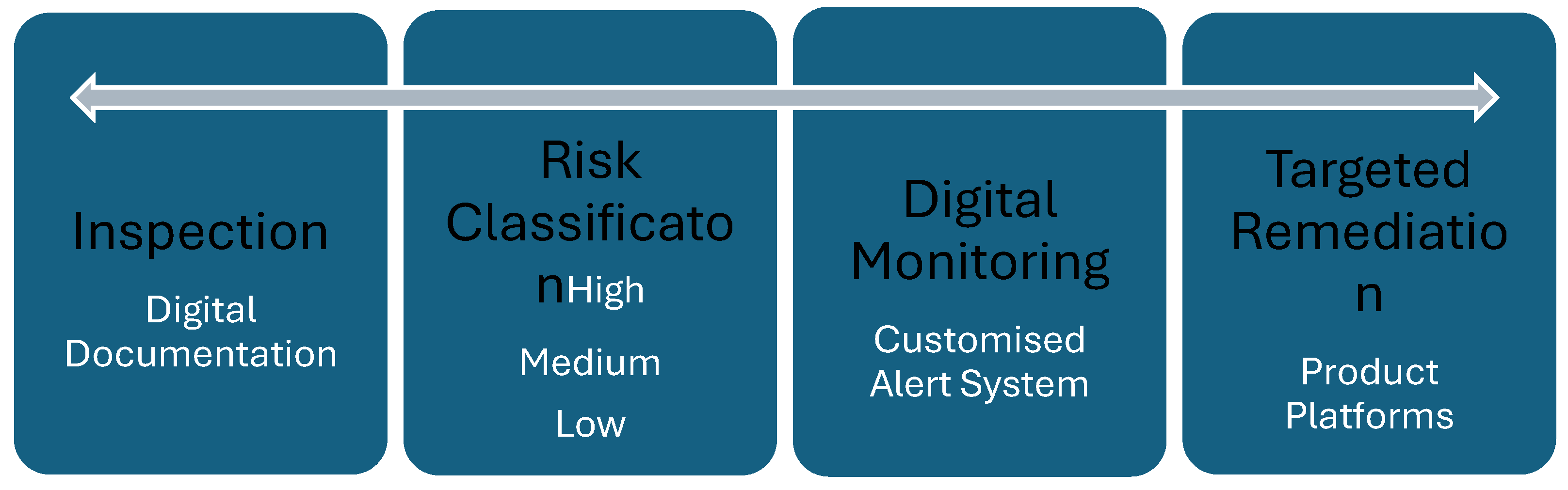
The challenge in current efforts is in the split in research, in which NDT methods are developed to be prototyped separately from DAM schemes. An improved framework characterised by NDT in inspection and surveying may entail using imaging technology (i.e.,: XBT and XCT) to capture a panel’s reinforcement without the need for destructive drilling, for which covermeters or radar scanning still give inconclusive results. However, recent research developments have experimentally validated the successful application of ground-penetrating radar (GPR) in detecting RAAC end bearing conditions [19]. The methodology relies on the use of a fabricated dielectric filled wedge that holds the GPR sensor at an angle relative to the surface of the RAAC panel. The field application of XCT as an NDT method for porous concrete has proven successful in evaluating the degree of clogging in porous concrete [20]. Where no high-risk conditions are established, risk mitigations may be applied before implementing a monitoring strategy for medium- and low-risk RAAC structures. The workflow of this monitoring scheme is demonstrated in Figure 6, in which an autonomous system is looped to produce a holistic understanding of an RAAC structure’s condition.
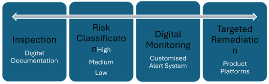
Figure 6.
Digital RAAC inspection and management process.
In the event of high-risk conditions, the panel may then be repaired or replaced, as has been carried out in current practices. The replaced panel may be transferred for additional testing, whereby other standardised NDT methods such as ultrasonic pulse velocity (UPV) may be studied for their validity of use in surveying existing RAAC panels. In a study exploring the effects of reinforcement on UPV readings, it is established that readings can be made reliable in low-density concretes by utilising a correction factor accounting for the rebar effect [21]. Other interesting NDT methods to explore include infrared thermography aimed at assessing moisture or thermal anomalies within RAAC panels. This can significantly impact the current risk category classification system through which the presence or extent of water damage can be ascertained, eliminating unnecessary remediation. This approach will also contribute to the continuing understanding of enhancing the lifecycle of existing RAAC panels, eliminating the unsustainable need to default to renovations.
There are immediate and long-term advantages in utilising an autonomous monitoring scheme. The use of the current cycle that includes the periodic allocation of time, costs, and labour for manual inspection is partially encouraged via DfE funding as a blanket solution for complete renovation. In adopting a manufacture-led approach, this cycle may be replaced with consistent inspection and specific remediation targets. In the end of service life of a panel for which replacement has been deemed necessary, the established knowledge of RAAC behaviour through monitoring can also facilitate its greater reuse potential. It has been documented that 10% of AAC can be used as a partial replacement for fine aggregate to reduce the density and enhance the compressive strength of concrete [22]. However, the recycling and reuse of AAC is a scarcely explored topic in the existing literature.
Given that RAAC was widely misused in the 1950s–1990s, the newly established standards for RAAC BS EN 12602 [23] and reinforcement optimisation according to BS EN 990 [24] promote the best practice for reliable design and manufacture to realise the material’s structural potential. This may support remediation efforts whereby optimised RAAC panels may be prototyped for retrofitting purposes capable of addressing the risk conditions reliably identified in monitor schemes. For instance, in roof construction for RAAC panels, builders apply bituminous roof membranes and paint the soffits immediately after manufacture, hence trapping the moisture in the panel and affecting the elastic modulus [3]. In future construction, improved RAAC lifecycles can be attained by using technology such as water barrier impregnation, produced specifically for a porous concrete matrix [25]. In renovation efforts, MTC recommends the utilisation of technology such as product platforms whereby common elements may be used across a newly built RAAC structure to enable the use of a renovation kit for parts in future defect remediation [16]. In addition, it may be worth exploring the potential of embedding sensors in newly built RAAC panels to enable a quantifiable comparison between existing and new RAAC structures, hence further supporting the agenda of DAM towards informed intervention measures.
In reference to the IStructE guidance presently used as a rulebook for RAAC inspection, remediation, and management [4], there is an inherent ambiguity in the information presented, which is largely qualitative. The guidance does not definitively recommend remediation tactics due to the observed interdependence of RAAC defects approximated in risk matrices. To determine the overall condition of a panel, it is necessary to evaluate defect observations with a considerable allowance for human error. The use of MCDA may alleviate this ambiguity by providing a structured quantification of the interdependent influences observed in RAAC panels. In establishing a standard benchmark for the influence of one defect over another, it may be possible to conduct structured evaluations of a panel’s overall condition. In establishing this relationship, future surveys may utilise this formulation as a reliable basis for remediation decision-making. The introduction of this methodology is particularly important as it promotes transparency among decision-makers and stakeholders managing the RAAC crisis. By providing a quantifiable framework, it standardises the evaluation process, reducing ambiguity and ensuring consistency in remediation decisions.
3. RAAC Decision-Making Framework
In appointing a suitable MCDA tool, the decision-making trial and evaluation laboratory (DEMATEL) was selected due to its confirmed reliability in determining interdependence among factors towards developing a guiding visual map for investigating and solving complicated and intertwined problems [26]. Moreover, in a recent review of the applications of DEMATEL, the authors ascertained that this tool is especially beneficial in subjective real-world problems with imprecise information, promoting it in this regard over other methods [27,28]. In relevance to RAAC remediation decision-making, the use of DEMATEL is especially relevant due to its capacity to include both qualitative and quantitative criteria to establish interdependencies for causal relationships [26]. Given that the IStructE guidance was formulated by a panel of experts, it is consulted in the establishment of the problem as well as its analysis using DEMATEL. The two categories of defects reported in the IStructE guidance are the panel construction and reinforcement condition; therefore, the following defects are identified as the four main causation clusters in DEMATEL analysis:
- Cracking and spalling (CS);
- Inadequate reinforcement (IR);
- Moisture ingress (MI);
- Excessive deflection (ED).
3.1. Methodology
The methodology adopted herein follows the standard DEMATEL method [26,29], which typically includes setting a threshold value to filter out negligible interdependencies in the total relation matrix (T) [30]. This step is often crucial in reducing complexity and highlighting significant relationships among factors. However, threshold values derived using relevant methods such as maximum mean de-entropy (MMDE) [31] and the average of all elements in the matrix, T [32], have proven to have a negligible impact on significant interdependencies and final results. Moreover, subtle interdependencies and influence values remain within a narrow range; hence, applying a threshold may impede comprehensive and transparent analysis.
Step 1: Calculate the average matrix, Matrix Z, based on the IStructE guidance explaining the relationship between defects and the subsequent risk category, where the scores range from 0 (no influence) to 4 (very strong influence). Since the IStructE guidance is consulted as a reliable source of information, the average matrix, Matrix Z, is directly derived from the provided scores without further averaging multiple expert inputs. In this case, l = 1.
where is the average influence score from factor i to factor j, is the number of experts, is the influence score from factor i to factor j given by expert , and is the total number of defects.
This simplifies the formula into the following:
where is the influence score from factor i to factor j, as per the IStructE guidance.
Step 2: Calculate the normalised initial direct-relation matrix, Matrix D, by normalising it, ensuring that the sum of each row in D is equal to 1.
where D is the normalised influence score from factor to factor , and is the average influence score from factor to factor .
Step 3: Obtain the total relation matrix, Matrix T:
where T is the total relation matrix; D is the normalised initial direct relation matrix; and is the identity matrix.
Step 4: Calculate the sums of rows and columns of Matrix T to determine the prominence and relation of each factor.
where represents the sum of the elements in row , indicating the total influence of factor i on other factors; is the element in the total relation matrix, Matrix T; and represents the sum of the elements in column , indicating the total influence of other factors on factor .
Step 5: Build the cause-and-effect relationship diagram by mapping all sets of coordinates to visualise the criteria’s complex interrelationships.
Step 6: Compute the overall condition score (OCS) by summing up the interdependency scores for each defect, which are derived from the influence scores in Matrix T.
where is the interdependency score for defect , and is the total number of defects.
The OCS score is then used to determine the appropriate remediation technique, as shown in Table 5.
Table 5.
Overall condition score for remediation decision.
3.2. Analysis
To conduct the DEMATEL analysis, the severity score of MI is deemed to be 4 by default, as per the IStructE recommendations. The scoring of other defects is shown in Table 6.
Table 6.
Severity of defect based on observed condition based on IStructE guidance [4].
In step 1, Table 7 shows the initial matrix resulting from the panel’s input on the impact of the defect clusters listed on the left (horizontal rows) on those positioned at the top (vertical columns).
Table 7.
Standard direct influence matrix (Z) for clusters.
In step 2, Table 8 shows the normalised matrix produced from the initial matrix. In step 3, Table 9, the final matrix is constructed based on the previous matrices. Finally, step 4 is achieved in Table 10 to show the prominence and relation of clusters.
Table 8.
Normalised direct influence matrix (D) for clusters.
Table 9.
Step 3: Total relation matrix (T) for clusters.
Table 10.
R and C and prominence and relation influences for clusters.
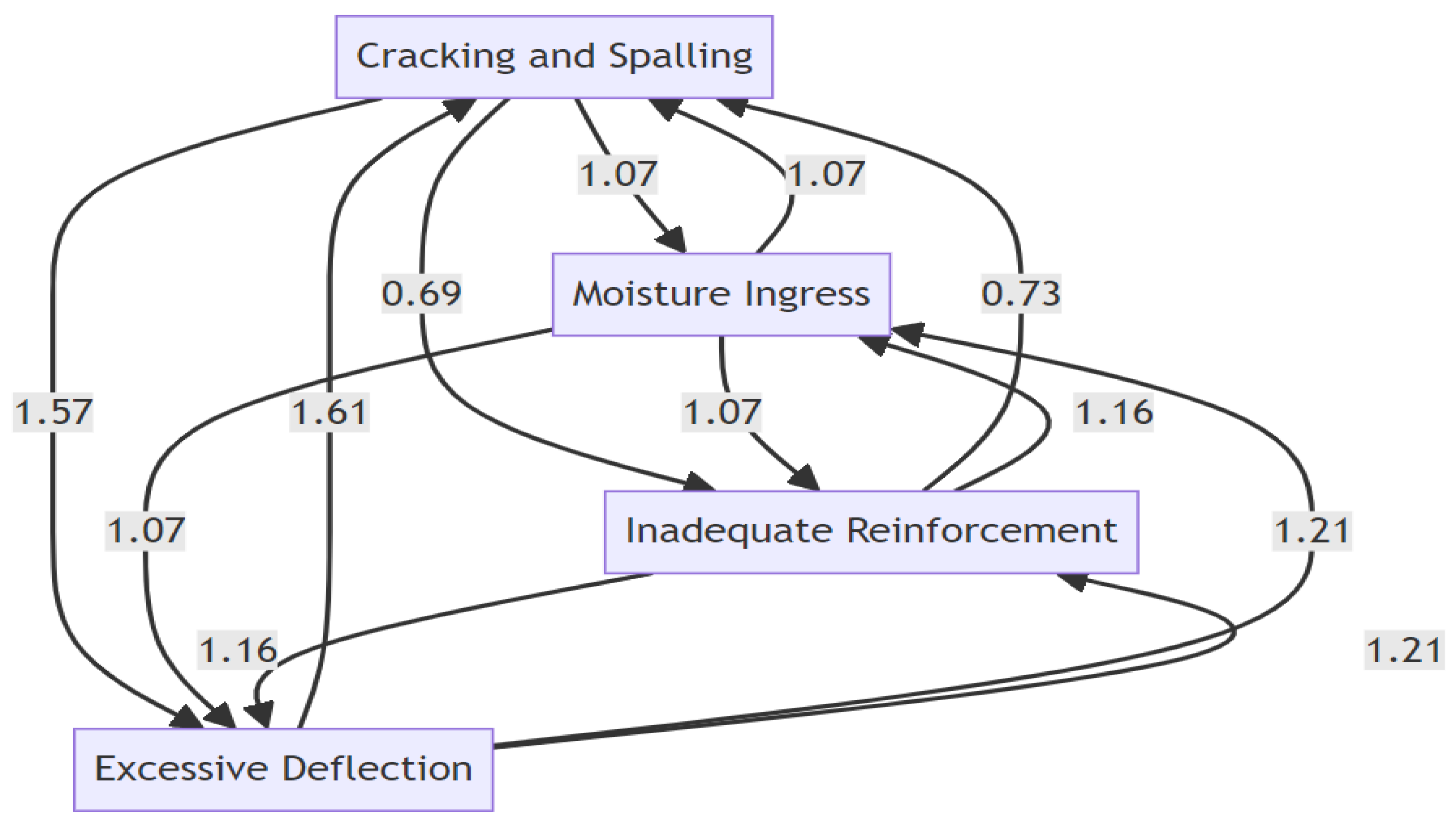
In analysing the prominence of and relation between defects, a four-quadrant impact relation map (IRM) is produced to visualise the appropriate designations for defects as either drivers or receivers [26]. The relations and prominence in Table 10 is visualised within the quadrants, produced by calculating the mean of R + C, as illustrated in Figure 7. Any defect located above zero on the R–C axis is a cause (i.e., a driver), and any defect below it is an effect (i.e., a receiver), as per the quadrant positions shown. Moreover, increasing importance is attributed to the defects located on the right side of the quadrant and vice versa. The weighted cause and effect of clusters is the final step produced in Figure 8.
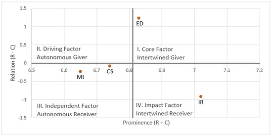
Figure 7.
Four−quadrant IRM for RAAC defect clusters.
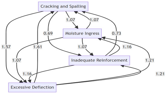
Figure 8.
RAAC defect cause–effect diagram.
3.3. Key Findings
The DEMATEL analysis provides valuable insights into the interdependencies and influences among various defects in RAAC panels. This is especially crucial given the ambiguity inherent in the deterioration mechanisms of RAAC as a porous structural material. Key findings from the analysis are discussed below.
- Defect IR in Quadrant IV:
- High Influence: IR has the highest column sum (C) value, indicating that it is significantly influenced by other defects;
- Impact Factor or Intertwined Receiver: IR’s high prominence but lower relation underscores its role as a major receiver of influences with significant weight in defect networks;
- Interdependencies: IR’s interdependence with MI and ED highlights the necessity of comprehensive reinforcement checks during construction and maintenance.
- Defect MI in Quadrant III:
- Central Role: Despite its lower prominence, MI’s higher relation indicates significant interactions with other defects;
- Independent Factor or Autonomous Receiver: MI’s influence on other defects, such as CS and inadequate reinforcement, IR, underscores its critical role in the defect propagation network.
- Defect CS in Quadrant III:
- Notable Influences: CS shows high row sum (R) values, indicating that it is a primary contributor to the deterioration of RAAC panels;
- Independent Factor or Autonomous Receiver: CS’s high relation hints at its dual role as a driver and receiver in the defect network, demonstrating the importance of early detection and repair to prevent further structural damage.
- Defect ED in Quadrant I:
- Secondary Nature: ED is prominently influenced by other defects, indicating its role as a secondary factor in the defect chain;
- Core Factor or Intertwined Giver: ED’s high prominence suggests that addressing deflection issues is crucial for managing overall RAAC panel conditions. For instance, ED issues directly instigate CS, triggering the subsequent defect network and further deteriorating the panel’s condition.
Overall, higher-prominence defects include ED and IR; these defects are critical as they have significant influence within the defect network. On the other hand, CS and MI are identified as having lower prominence; however, their positions within the IRM indicate nuanced roles. Ultimately, the MCDA model successfully accounts for the intricate complexities inherent in RAAC defect observations. By addressing high-prominence defects such as ED and IR, while also considering the complex interdependencies revealed through cause–effect analysis, a more effective long-term maintenance strategy for RAAC panels can be developed. This integrated approach ensures that both primary and secondary defects are managed, reducing the likelihood of defect propagation and enhancing the structural integrity of RAAC panels. These findings provide a robust framework for surveyors and engineers to prioritise defect monitoring, and remediation efforts based on the quantified interdependencies established through the DEMATEL method. This structured approach enhances the accuracy of the OCS and can inform standardised remediation decisions.
Validation of this methodology for practical application remains challenging due the lack of case studies showcasing the remedial solution that can be opted for to address defective RAAC panels. It is reported that RAAC suppliers typically carry out widespread remedial solutions or remove panels without any formal record or feedback [3]. However, based on the case study of the 1981 complex with affected RAAC panels shown in Table 4, it is possible to apply the methodology proposed herein as an attempt to obtain a validated prototype given that the remedial action taken is the replacement of RAAC panels [3]. In using Equations (6) and (7) shown in Step 6, the values shown in Table 11 are computed, illustrating an OCS that exceeds 50, hence reliably indicating severe issues necessitating panel replacement.
Table 11.
Case study remediation recommendation based on DEMATEL.
It is worth noting that although this methodology may lack extensive validation, it offers significant contributions in that it serves to enhance the clarity of IStructE guidance to all stakeholders. In establishing the prominence and relation of defects, it is possible to reduce the ambiguity inherent in RAAC surveying and monitoring procedures. Moreover, this model may be improved through continuous implementation, which can facilitate the application of a quantifiable approach in RAAC retrofitting and decision-making. This MCDA framework may also be integrated within a customised code to serve as a reliable threshold for custom alert systems across digitally surveyed RAAC panels. By introducing a feedback loop through continuous implementation, this framework may be enhanced towards reliable automation and standardisation to ensure its relevance in DAM systems.
4. Conclusions and Future Directions
The early construction practises of RAAC structures showed engineering and manufacturing negligence, which led to exceptionally compromised lifecycle performances. This highlights the timeliness and criticality of careful inspection and retrofitting procedures. In contrast to the current guidance for RAAC surveying in which invasive inspections are suggested, this paper proposed a novel framework inspired by the known properties of and common defects observed in RAAC panels. This framework is primarily a preventative approach, in contrast to the reactive approach suggested in current guidance. It is characterised by a reliance on the digitisation and automation of surveying practises, suggesting their application in DAM processes. To support this, a literature review was conducted to identify existing case studies to address possibly overlooked RAAC defects. The application of the MCDA approach using the DEMATEL method in this study offers a structured and quantifiable framework for evaluating the condition of RAAC panels. This study demonstrates the utility of the MCDA approach, particularly the DEMATEL method, in providing a structured and quantifiable framework for assessing RAAC panels. The methodology effectively calculates an OCS, guiding appropriate remediation actions by categorising severity levels. By elucidating the interdependencies among defects, the DEMATEL method enhances the precision and reliability of RAAC condition assessments, translating IStructE guidance into actionable recommendations. The calculated OCS ranges facilitate informed decision-making by categorising the severity of issues and recommending specific remediation actions, from routine maintenance for minor issues to panel replacement for severe conditions. This approach standardises RAAC management, reducing ambiguity in engineering judgments.
Future research may aim to address the scarcity of literature on the engineering properties and failure behaviour of RAAC as a structural material. The utilisation of NDT methods in porous concrete structures is a challenge due to the peculiarity of the largely non-solid matrix inhibiting accuracy, as observed in standard concrete. As such, it is recommended that any replaced RAAC structure is utilised for testing in controlled conditions to establish the reliability of NDT methods for future field surveying. The decision-making framework proposed herein may also benefit current efforts towards the digitalisation of RAAC management. It is worth investigating the embedment of this framework within technological evolvements in renovation. For example, the framework may readily enable automated recommendations for remediation strategies as a secondary element to digitally stored surveying data.
Author Contributions
Conceptualization, D.A.; methodology, D.A.; validation, D.A.; formal analysis, D.A.; investigation, D.A.; resources, D.A.; data curation, D.A.; writing—original draft preparation, D.A.; writing—review and editing, D.A. and L.D.S.; visualization, D.A.; supervision, L.D.S.; project administration, L.D.S.; funding acquisition, L.D.S. All authors have read and agreed to the published version of the manuscript.
Funding
This research received no external funding.
Data Availability Statement
Data are contained within the article.
Conflicts of Interest
The authors declare no conflicts of interest.
References
- Currie, R.J.; Matthews, S.L. Information Paper 10/96 Reinforced Autoclaved Aerated Concrete Planks Designed before 1980; BRE—Publication Index|NBS: Bracknell, UK, 1996; Available online: https://www.thenbs.com/PublicationIndex/documents/details?Pub=BRE&DocID=98696 (accessed on 24 October 2023).
- Matthews, S.; Narayanan, N.; Goodier, A. Report BR 445 Reinforced Autoclaved Aerated Concrete Panels: Review of Behaviour and Developments in Assessment and Design; BRE—Publication Index|NBS: Bracknell, UK, 2002; Available online: https://www.thenbs.com/PublicationIndex/documents/details?Pub=BRE&DocID=260492 (accessed on 26 December 2023).
- Campbell, P. Learning from Construction Failures: Applied Forensic Engineering; Wiley: New York, NY, USA, 2001; pp. 206–226. [Google Scholar]
- Istructe.org. Reinforced Autoclaved Aerated Concrete (RAAC) Investigation and Assessment—Further Guidance—The Institution of Structural Engineers. 2023. Available online: https://www.istructe.org/resources/guidance/reinforced-autoclaved-aerated-concrete-(raac)-inve/ (accessed on 25 October 2023).
- Qu, X.; Zhao, X. Previous and present investigations on the components, microstructure and main properties of autoclaved aerated concrete—A review. Constr. Build. Mater. 2017, 135, 505–516. [Google Scholar] [CrossRef]
- Laukaitis, A.; Kerienė, J.; Mikulskis, D.; Sinica, M.; Sezemanas, G. Influence of fibrous additives on properties of aerated autoclaved concrete forming mixtures and strength characteristics of products. Constr. Build. Mater. 2009, 23, 3034–3042. [Google Scholar] [CrossRef]
- Tanner, J.; Varela, J.; Brightman, M.; Cancino, U.; Argudo, J.; Klingner, R. Seismic performance and design of autoclaved aerated concrete (aac) structural systems. In Proceedings of the 13th World Conference on Earthquake Engineering, Vancouver, BC, Canada, 1–6 August 2004. Available online: https://www.iitk.ac.in/nicee/wcee/article/13_541.pdf (accessed on 5 January 2024).
- Bonakdar, A.; Babbitt, F.; Mobasher, B. Physical and mechanical characterization of Fiber-Reinforced Aerated Concrete (FRAC). Cem. Concr. Compos. 2013, 38, 82–91. [Google Scholar] [CrossRef]
- Reinforced Autoclaved Aerated Concrete (RAAC): Identification Guidance. 2024. Available online: https://www.gov.uk/government/publications/reinforced-autoclaved-aerated-concrete-estates-guidance (accessed on 11 July 2024).
- Health and Safety Executive HSE Books. 2012. Available online: https://www.hse.gov.uk/pubns/priced/hsg264.pdf (accessed on 24 January 2024).
- Loughborough University. Loughborough Researchers behind ‘First of Its Kind’ AI Tool That Aims to Cut Time Needed to Survey and Maintain RAAC. 2023. Available online: https://www.lboro.ac.uk/news-events/news/2023/october/new-ai-tool-to-survey-raac (accessed on 24 January 2024).
- Matthews, S.; Narayanan, N.; Goodier, A. IP 7/02 Reinforced Autoclaved Aerated Concrete Panels: Test Results, Assessment and Design; BRE—Publication Index|NBS: Bracknell, UK, 2002; Available online: https://www.thenbs.com/PublicationIndex/documents/details?Pub=BRE&DocID=257354 (accessed on 6 January 2024).
- Department for Education. UK Government Web Archive. 2023. Available online: https://webarchive.nationalarchives.gov.uk/ukgwa/20231030194200/https://www.gov.uk/government/publications/reinforced-autoclaved-aerated-concrete-raac-management-information (accessed on 10 February 2024).
- Area Guidelines for Mainstream Schools Building Bulletin 103. 2014. Available online: https://assets.publishing.service.gov.uk/media/5f23ec238fa8f57acac33720/BB103_Area_Guidelines_for_Mainstream_Schools.pdf (accessed on 10 February 2024).
- Department for Education. Government Confirms Plans to Permanently Remove RAAC from All Schools and Colleges in England. 2024. Available online: https://www.gov.uk/government/news/government-confirms-plans-to-permanently-remove-raac-from-all-schools-and-colleges-in-england (accessed on 25 February 2024).
- Written Evidence Submitted by the Manufacturing Technology Centre (MTC). 2022. Available online: https://committees.parliament.uk/writtenevidence/122316/pdf/ (accessed on 26 February 2024).
- C-DICE. Industrial Secondment: Reinforced Autoclaved Aerated Concrete (RAAC) Monitoring. 2024. Available online: https://www.cdice.ac.uk/news/everyware (accessed on 1 March 2024).
- Davies-Holloway, C. Airedale General Hospital Manages RAAC Risk with Indoor Mapping; Association for Geographic Information: Fareham, UK, 2024; Available online: https://www.agi.org.uk/airedale-general-hospital-manages-raac-risk-with-indoor-mapping/ (accessed on 17 June 2024).
- Elliott, J.B.; Chaney, D. Angled Ground Penetrating Radar to Detect and Position Reinforcement and Bearing Lengths within Reinforced Autoclaved Aerated Concrete Planks. 2024. Available online: https://ssrn.com/abstract=4813203 (accessed on 6 July 2024).
- Manahiloh, K.N.; Muhunthan, B.; Kayhanian, M.; Gebremariam, S.Y. X-ray Computed Tomography and Nondestructive Evaluation of Clogging in Porous Concrete Field Samples. J. Mater. Civ. Eng. 2012, 24, 1103–1109. [Google Scholar] [CrossRef]
- Fodil, N.; Chemrouk, M.; Ammar, A. The influence of steel reinforcement on ultrasonic pulse velocity measurements in concrete of different strength ranges. IOP Conf. Ser. Mater. Sci. Eng. 2019, 603, 022049. [Google Scholar] [CrossRef]
- Alik, A.; Majid, M. View of Physical and Mechanical Properties of Autoclaved Aerated Concrete (AAC) as Partial Fine Aggregate in Concrete. 2023. Available online: https://publisher.uthm.edu.my/periodicals/index.php/rtcebe/article/view/5745/3487 (accessed on 14 March 2024).
- BS EN 12602:2016; Prefabricated Reinforced Components of Autoclaved Aerated Concrete. BSI: London, UK, 2016.
- BS EN 990:2002; Test Methods for Verification of Corrosion Protection of Reinforcement in Autoclaved Aerated Concrete and Lightweight Aggregate Concrete with Open Structure. BSI: London, UK, 2002.
- Holman, H. Mitigation through Impregnation—Solving the Ongoing RAAC Issue. 2023. Available online: https://www.nano-care.co.uk/2023/09/mitigation-through-impregnation-solving-the-ongoing-raac-issue/ (accessed on 18 June 2024).
- Si, S.-L.; You, X.-Y.; Liu, H.-C.; Zhang, P. DEMATEL Technique: A Systematic Review of the State-of-the-Art Literature on Methodologies and Applications. Math. Probl. Eng. 2018, 2018, 3696457. [Google Scholar] [CrossRef]
- Chen, C.-Y.; Tzeng, G.-H.; Huang, J.-J. Generalized Dematel Technique with Centrality Measurements. Technol. Econ. Dev. Econ. 2017, 24, 600–614. [Google Scholar] [CrossRef]
- Kumar, A.; Dixit, G. Evaluating critical barriers to implementation of WEEE management using DEMATEL approach. Resour. Conserv. Recycl. 2018, 131, 101–121. [Google Scholar] [CrossRef]
- Pinto, B.M.B.; Ferreira, F.A.F.; Spahr, R.W.; Sunderman, M.A.; Pereira, L.F. Analyzing causes of urban blight using cognitive mapping and DEMATEL. Ann. Oper. Res. 2022, 325, 1083–1110. [Google Scholar] [CrossRef] [PubMed]
- Sumrit, D. Using DEMATEL Method to Analyze the Causal Relations on Technological Innovation Capability Evaluation Factors in Thai Technology-Based Firms. 2013. Available online: https://api.semanticscholar.org/CorpusID:18646142 (accessed on 14 July 2024).
- Lee, P.T.-W.; Lin, C.-W. The cognition map of financial ratios of shipping companies using DEMATEL and MMDE. Marit. Policy Manag. 2013, 40, 133–145. [Google Scholar] [CrossRef]
- Sara, J.; Stikkelman, R.M.; Herder, P.M. Assessing relative importance and mutual influence of barriers for CCS deployment of the ROAD project using AHP and DEMATEL methods. Int. J. Greenh. Gas Control. 2015, 41, 336–357. [Google Scholar]


Disclaimer/Publisher’s Note: The statements, opinions and data contained in all publications are solely those of the individual author(s) and contributor(s) and not of MDPI and/or the editor(s). MDPI and/or the editor(s) disclaim responsibility for any injury to people or property resulting from any ideas, methods, instructions or products referred to in the content. |
© 2024 by the authors. Licensee MDPI, Basel, Switzerland. This article is an open access article distributed under the terms and conditions of the Creative Commons Attribution (CC BY) license (https://creativecommons.org/licenses/by/4.0/).