Abstract
The steel rib and the lattice girder are two typical steel arch frames used in the primary lining of the New Austrian Tunnelling Method (NATM) highway tunnel. In the process of tunnel construction, it is necessary to choose the support method according to the mechanical properties, durability, construction difficulty, and economic benefits. In order to analyze the mechanical characteristics of steel arch frames, a loading and measurement test system for steel arch was designed, and destructive tests were carried out on a three-bar lattice girder, four-bar lattice girder, and I-beam steel rib. The steel utilization coefficient was introduced to compare the mechanical properties of the different types of steel frames. The results show that the I-beam steel rib has the largest steel utilization coefficient, but it is not well combined with concrete. Among the lattice girders, the three-bar W-shaped lattice girder uses the least amount of steel under the same load, which reduces the construction cost and is worth applying and popularizing. Additionally, the steel utilization coefficient of different types of lattice girders can be optimized through the ratio of steel bar diameters. It is proved that the steel utilization coefficient can provide a reference for the evaluation and selection of steel frames for the primary lining of highway tunnel engineering.
1. Introduction
The steel rib and the lattice girder are two types of steel frames commonly used in the primary lining of highway tunnels. Steel frames are the main element that withstands the pressure of surrounding rock and controls the deformation after tunnel excavation. They perform a role in ensuring the safety of the tunnel before the strength of the shotcrete reaches the design value. Once the strength of the shotcrete has reached the design value, the steel arch will be combined with the shotcrete and becomes the initial support for the tunnel and bears the permanent load of surrounding rock. For this concern, whether it is more reasonable to adopt a steel rib or lattice girder during the design and construction of tunnel primary lining has been a hot issue in tunnel engineering and academic circles.
Many scholars have carried out a lot of significant research on the primary lining of tunnels. A general method is the lattice girder, with laboratory and field tests being the common way to assess it. Meanwhile, the reinforcement effect is often compared with the steel rib. Li [1,2] conducted a comparative field test relying on the Zhengxi high-speed railway loess tunnel project. Li’s study showed that in the design of the primary lining for tunnels under such soil conditions as grade IV clayey old loess, the steel rib is more economical and faster to construct. At the same time, it is advisable to use the steel rib as the primary lining for tunnels in geological conditions such as class V sandy new loess. Zhang [3] conducted a systematic study of the two types of structures through indoor performance tests of a steel rib and lattice girder, and concluded that the ultimate bearing capacity of the steel rib is about 16% higher than that of the lattice girder. Moreover, simulation modeling can be used to validate the test results. Liu [4] studied the deformation behaviors and mechanical mechanisms of a large-span tunnel excavated in a chlorite schist formation with the single primary lining method and the double primary lining method by in situ tests and numerical simulation. In order to investigate the support characteristics of the steel sets embedded in tunnel primary lining, Wong [5] proposed a series of analytical models for various modes of loading on an infinite cylinder. Smaniotto [6] presented a comprehensive experimental program on the mechanical, hygral, and thermal behavior of a modern wet mix shotcrete, which laid the foundation for the thorough calibration and validation of material models. Wang [7] established a nonlinear buckling simulation to investigate the buckling characteristic, the failure mode, the bearing capacity, and the in-plane and out-plane deformation of the π-type steel–concrete composite support (SCCS) arch under different gradient-distributed (GD) loads. The stability of the π-type SCCS arch with different wall thicknesses was identified and the corresponding anti-buckling measures for the in-plane and the out-of-plane stability were proposed. Embaby [8] studied the performance characteristics of very large-span soil–steel structures based on field measurements and the three-dimensional (3D) finite element model (FEM). The numerical results indicated that two main critical zones of the steel structure, the crown and at the change in arc radii (40 degrees from the top arc on each side), were observed to experience high axial stresses. Zhang [9] proposed physical model tests to investigate the soil pressure distribution, the internal force variation, and the lining damage pattern. It was concluded that distinct differences exist, particularly for the lining close to the thinning area of multi-arch tunnels. Liu [10,11] presented several numerical models to study the deformation and damage of tunnels subjected to strike-slip faulting, focusing on the effects of tectonic stress and cross-sectional shape. Results show that tectonic stress has apparent effects on the transverse displacement of the tunnel axis and the compressive damage range. Zhou [12] studied the mechanical behavior, failure causes, failure mechanisms, and treatment techniques of the tunnel’s initial support structure by field monitoring, systematic analysis, and field test results. By implementing local long anchors or bolts, the stress distribution within the initial support structure of a large-span tunnel can be effectively enhanced.
Several evaluation methods are also presented. For instance, Kim [13] presented an evaluation of the structural performance of tetragonal lattice girders for the New Austrian Tunnelling Method (NATM) tunnel construction. A new support technology of a spatial steel tubular grid (SSTG) arch with high strength and large stiffness was presented by Song [14], and he carried out the bending tests combined with the excavation tunnel project of Panyu Square Station in Guangzhou. Li [15] optimized the design parameters of wave thickness, wave height, and wave pitch of initial support of corrugated steel combined with a sensitivity analysis of tunnel convergence, and the internal force of corrugated steel and the second liner. Xu [16] presented the applied calculation method of 3D elastic–plastic numerical back analysis based upon FLAC (3D). Part of the studies are based on engineering projects, and the technologies can be immediately applied. Zhang [17] found that the single-layer primary support with I20b as the main support framework cannot control the large deformation of high ground stress tunnel based on the national highway 569 Mandala Datong highway Ningchan tunnel. Chen [18,19] put forward the long and short associate contour blastholes (LSACB) pattern, which had been applied in metro tunnels in Qingdao. Song [20] analyzed the mechanical and deformation characteristics of the support system by numerical simulations and the in situ monitoring of data in the case of the Xinggongjie Station subway tunnel. Several experimental tests have also been presented to prove the behavior of lattice girder on the tunnels [11,21,22,23].
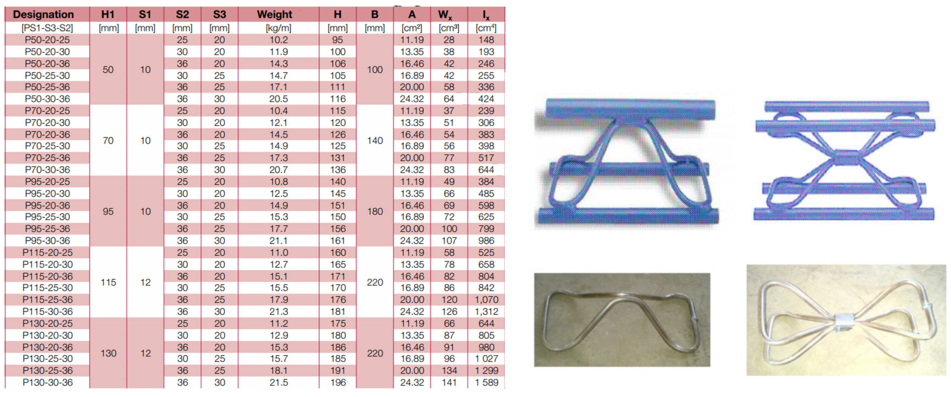
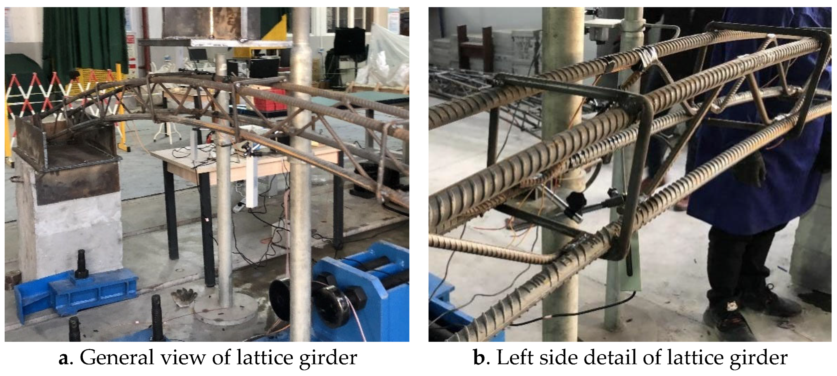
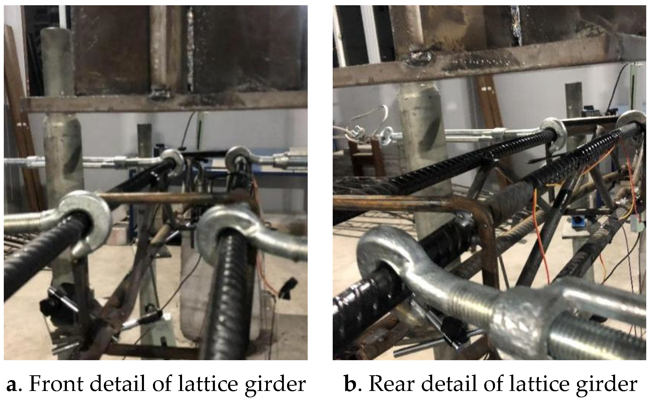
In terms of the design and research of the lattice girder, there is still no unified design standard. The three-bar lattice girder and four-bar grid are mainly used in tunnel engineering. Table 1 shows the parameters of the lattice girder in some design institutes in China, which indicates that most of the projects adopt a four-bar lattice girder, and lattice girders vary greatly in different projects under the same surrounding rock level. The United States and some European countries prefer three-bar lattice girders, whose production standards and product displays are shown in Figure 1 and Figure 2. Through the comparison of common types of lattice girders in China and European countries, it is found that European products have sound standards and can be industrialized, while there is no general standard for domestic lattice girders in China. The design of lattice girders is mainly based on experience, and theoretical research on lattice girders requires development to guide the design and construction.

Table 1.
Design of lattice girders in some Chinese design institutes.
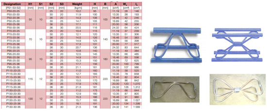
Figure 1.
Lattice girders manufactured by DSI.
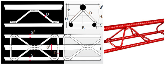
Figure 2.
Lattice girder manufactured by BEFER.
Although a large amount of literature has provided detailed analyses of primary lining materials, properties, and adaptability under different geological conditions, the selection and application strategy of grilles in specific tunnel types is still a field that needs to be refined and innovative. According to Table 1, the weight of steel per frame in the two-lane tunnels is between 360 and 615 kg, which means that compared with the bearing capacity, the amount of steel used is not taken seriously in the design. Therefore, the steel utilization coefficient was introduced to scientifically evaluate the bearing performance of the steel frame structure in this paper. The loading and measurement test system for steel arch was designed, and destructive tests were carried out on a three-bar W-shaped lattice girder, four-bar W-shaped lattice girder, four-bar double 8-shaped lattice girder, and I-shaped steel rib. The mechanical characteristics, deformation evolution mechanism, and failure development law of each type of steel frame are studied. The research results can provide a reference for the selection and design of steel frames for tunnel primary linings.
2. Design of Laboratory Test
2.1. Loading and Measuring Platform
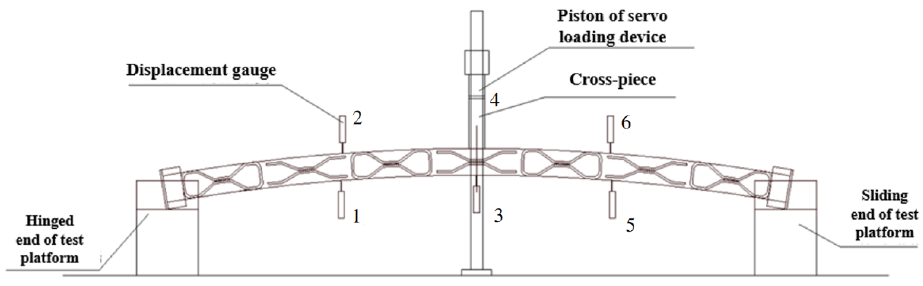
Under different grades of the surrounding rock, the actual stress distribution of the tunnel lining is quite complex, and the boundary conditions at both ends of the steel arch sections will also be affected by the deformation of the surrounding rock and adjacent sections. Due to the limitation of laboratory test conditions, the loading test of the whole steel frame was not carried out. Only one section of the steel frame was selected in this test to analyze the failure characteristics and ultimate bearing capacity of the two types of steel arches. The vertical displacement of the tunnel vault is usually greater than that of other parts, so for the bare arch, the settled surrounding rock will first contact the steel frame at the arch and exert vertical pressure. Meanwhile, the two ends of the steel frame are not in contact with the surrounding rock, so there is a space for horizontal displacement. For this concern, a more reasonable loading test method was set up (as shown in Figure 3). Six monitoring points (1-6, as well as lower left, upper left, lower center, upper center, lower right and upper right) were set up to record vertical displacement of the steel frame. One end of the member is hinged constraint, and the other end is unrestrained, so that it can slide freely. The surrounding rock pressure, which is simplified to a concentrated load, is applied on the vault of the member. In this way, the loading test can reflect the differences in the force, deformation, and failure characteristics of different types of steel arches.
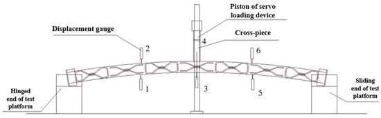
Figure 3.
Schematic diagram of the loading and measuring platform for steel arch.
The loading and measuring platform for the steel arch was designed for this laboratory test (as shown in Figure 4). As shown in Figure 5, two equal-height concrete blocks (A) are placed on both ends of the test platform, and large steel plate (B) is welded on the concrete block (A). Weld steel plate (C) close to concrete block (A) on the front and rear sides of steel plate (B) to ensure the holding force of the upper steel plate. Weld steel plate (D) on the left and right sides of steel plate (B) to ensure that the member will not overturn when loaded. Steel plate (E) is welded at the hinged end of the steel arch to realize the constraint form of the hinge when loaded, and lubricating oil is applied at the sliding end.
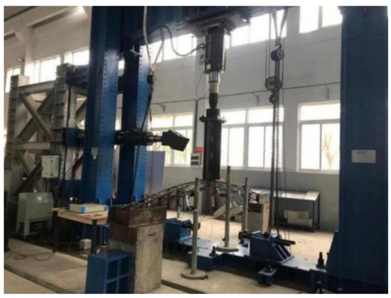
Figure 4.
The loading and measuring platform for steel arch.
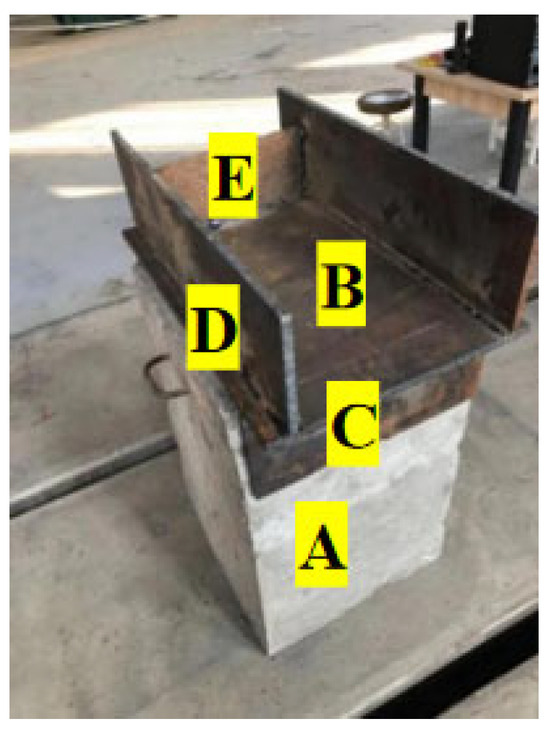
Figure 5.
Test platform restraint.
The loading equipment of this test, ZBM2000 (Shanghai Chubang measurement and control Technology Co., Ltd., Shanghai, China), is an electro-hydraulic servo shear compression test system, which can apply a vertical load up to 2000 kN, meeting the requirements of this test. At the lower part of the loading piston, a cross-shaped component is connected by bolts, so that the jack can have good contact with the component. Two displacement gauges (located at the upper and lower edges, respectively) are installed every quarter span of the steel arch. The model is ZY-DT100 (Shanghai Chubang measurement and control Technology Co., Ltd, Shanghai, China), and the maximum displacement that can be measured is 100 mm. A total of six displacement gauges are installed for each member.
After installation of the steel arch, the piston of the servo loading equipment slowly moves down until it contacts the steel arch, and then the loading value increases slowly under the control of the computer. A 2 kN loading is added at each stage, and then hold the force for 2 min after loading, which lasts 30 s, to ensure the stability of the steel arch. The process continues till the steel arch is destroyed.
2.2. Test Working Conditions
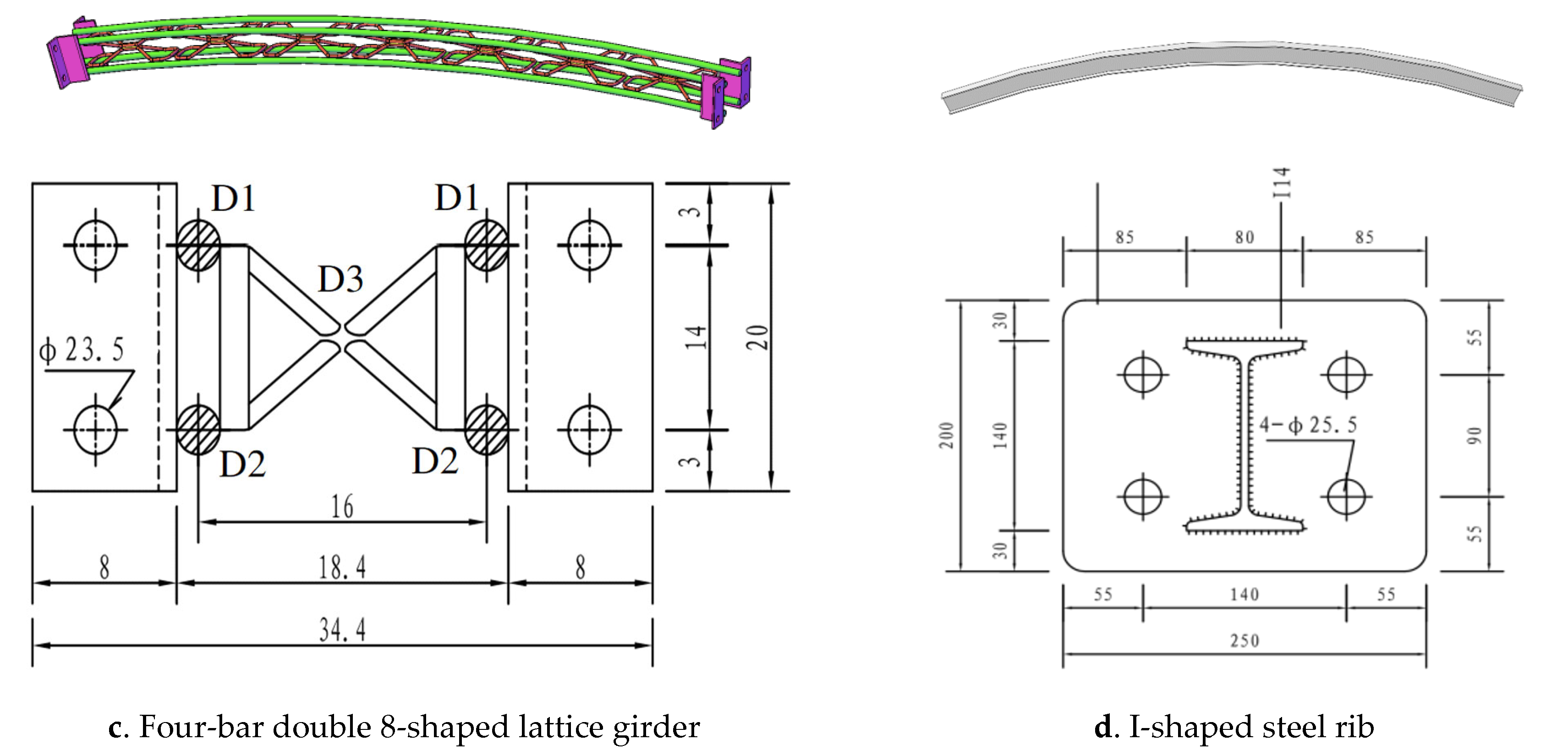
There are various types of steel arches currently used in the design of tunnel primary lining, with I-shaped steel rib being the mainstream, and lattice girders mainly contain four-bar double 8-shaped lattice girder, four-bar W-shaped lattice girder, and three-bar W-shaped lattice girder. Based on the steel frame design of a standard highway tunnel in China (the surrounding rock grade is grade IV), the test group was divided into 10 groups (13 members), including 3 groups of four-bar double 8-shaped lattice girders (4 members), 3 groups of four-bar W-shaped lattice girders (4 members), 3 groups of three-bar W-shaped lattice girders (4 members) and 1 group of I-shaped steel rib (1 member). The models of the three types of lattice girders and I-shaped steel rib involved and the cross-section in this test are shown schematically in Figure 6.
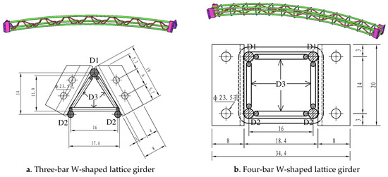
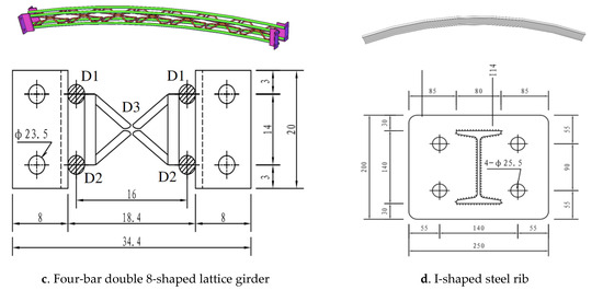
Figure 6.
Diagram and cross-section of various types of steel frames.
The specific test conditions are shown in Table 2. The lattice girder is made of HRB400 (whose standard yield strength is 400 MPa) hot-rolled ribbed steel bar, the section size is b × h = 140 mm × 140 mm, D1 is the diameter of the upper main bar of the lattice girder, D2 is the diameter of the lower main bar of the lattice girder, and D3 is the diameter of the web reinforcement of the lattice girder. The four-bar W-shaped lattice girder and the three-bar W-shaped lattice girder are set with a stirrup of 10 mm diameter every 55 cm, the four-bar double 8-shaped lattice girder is not set with stirrups. The main bar at the lower part of all grids is 549 cm, the height from arch bottom to arch crown is 50 cm, and the length of both ends is 392 cm. I-shaped steel ribs are used for the steel frame, where h is the height of the steel rib, b is the width of the steel rib, d is the thickness of the web, and t is the thickness of the flange. According to Figure 1, 25 mm and 22 mm are commonly chosen as D1 and D2, respectively, but there are various values for D3. Therefore, D3 is a main parameter in the controlled experiment shown in Table 2.
Table 2.
Test conditions of various types of steel frames.
2.3. Steel Utilization Coefficient
In order to quantitatively compare the mechanical properties of various types of steel frames, the steel utilization coefficient as I (as shown in Formula (1)) is introduced for comparison. The steel utilization coefficient can be obtained by the ratio of the ultimate failure load to the steel consumption of the steel frame. The higher the value of the steel utilization coefficient, the higher the comprehensive performance of the steel frame, which can better play its value in highway tunnel engineering.
where I is the steel utilization coefficient of the tunnel steel arch under concentrated load (kN/kg); Pi is the ultimate failure load of each test member (kN); and ρi is the steel consumption of each test member (kg).
3. Analysis of Test Results
3.1. Three-Bar W-Shaped Lattice Girder
- (1)
- Failure mode
It can be concluded from the test results that the failure mode of the three-bar W-shaped lattice girder with different web bar diameters is slightly different. During the loading process of steel frame LG-3W-10-1, with the increase in load, the stirrups in the midspan of the steel frame gradually yield, and show obvious yield deformation. Meanwhile, the upper main bar also begins to yield and deform gradually. After unloading, it is obvious that both the web bar in the midspan and the upper main bar have large deformation, and the yield point is located in the upper main bar of the whole section of the midspan (as shown in Figure 7). During the loading process of steel frame LG-3W-12-1, with the gradual increase in load, the upper main bar in the midspan of the steel frame gradually yields, and obvious yield deformation occurs. The midspan area of the steel frame bends downward as a whole. After unloading, it can be clearly seen that the upper main bar in the midspan produces large deformation, and the yield point is located at the connection between the main bar and the stirrup in the midspan (as shown in Figure 8). The failure process of steel frame LG-3W-14-1 is similar to that of steel frame LG-3W-12-1, and the yield point is located at the connection between the main bar and the stirrup in the midspan.

Figure 7.
Loading failure of steel frame LG-3W-10-1.
Figure 8.
Loading failure of steel frame LG-3W-12-1.
- (2)
- Displacement–load relationship
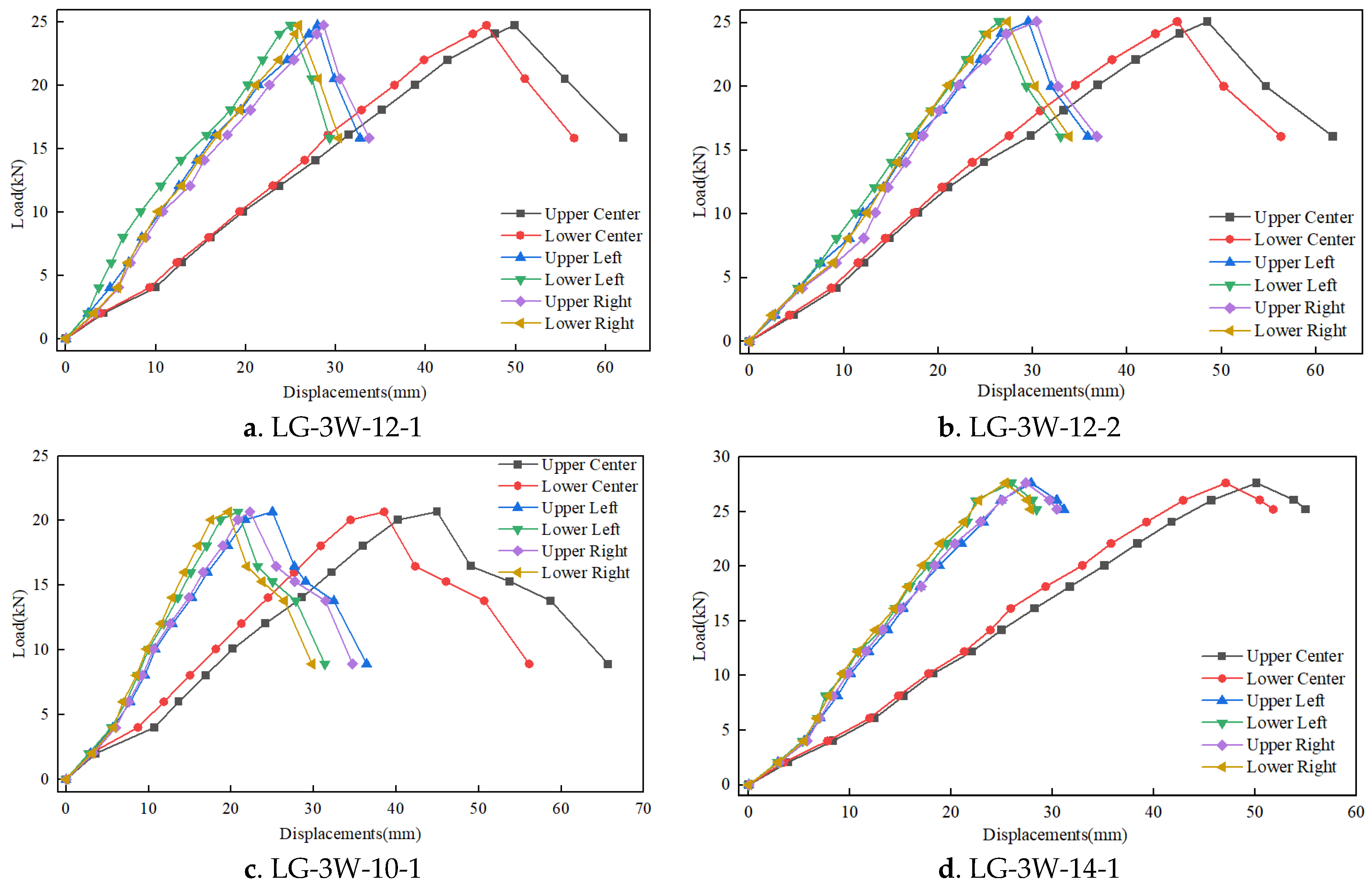
The displacement–load curves of three-bar W-shaped lattice girders are shown in Figure 9. By analyzing the loading process, final failure mode, and displacement–load relationship of each steel frame, the deformation of the steel frame can be mainly divided into three main stages:
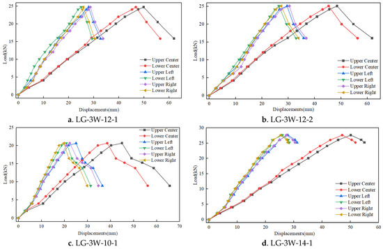
Figure 9.
Load–displacement curves of three-bar W-shaped lattice girder.
- I.
- When the load is small, the whole steel frame is in the elastic stage. The deformation of each measuring point is linear with the applied load. The distribution of stress on elements is uniform with high stability of the steel frame.
- II.
- With the continuous increase in load, the upper main bar in the midspan of LG-3W-12-1 and LG-3W-14-1 first enters the strengthening stage, and the deformation gradually increases. However, the deformation of the web bar was not obvious (the web bar in the midspan of LG-3W-10-1 firstly enters the strengthening stage, the deformation gradually increases, and drives the deformation of the upper main bar). At this time, the midspan deformation is no longer linear with the applied load, the displacement at each loading stage begins to increase, and the growth rate of the midspan deformation is greater than that of the two sides. At this time, the overall stability of the steel frame begins to decrease and the stress distribution is no longer uniform, especially as the upper main bar in the midspan changes from the original arch shape to horizontal shape, but the steel frame can still withstand the external load.
- III.
- The upper main bars of LG-3W-12-1 and LG-3W-14-1 are pressed into a horizontal state when the load applied hits the limit. The stirrup in the midspan of LG-3W-10-1 begins to show obvious bending deformation while driving the upper main bar to bend downward. The deformation starts to accelerate when the load decreases slowly. After reaching the critical value, the displacement begins to increase rapidly. Meanwhile, the steel frame is judged to have been completely destroyed and the loading is terminated. The failure position is in the midspan, but the structure on both sides of the steel frame is still in the elastic stage, and its mechanical properties are not significantly affected.
- (3)
- Comparative analysis of test results
From the results above, the load and corresponding displacement of each steel frame at the stage of failure are shown in Table 3, and the steel utilization coefficient for each steel frame is calculated in Table 4. The following conclusions can be drawn with the help of test data and the failure mode of the steel frame.
Table 3.
Ultimate load and failure displacement of three-bar W-shaped lattice girder.
Table 4.
Steel utilization coefficient of three-bar W-shaped lattice girder.
- I.
- Through comparison, with the increase in the diameter of the web bar, the ultimate bearing capacity of the steel frame is enhanced, and the steel utilization coefficient increases by 4.1% (10–12) and 2.9% (12–14), respectively. The lifting proportion reduces gradually, indicating that the load-bearing capacity of the lattice girder by increasing the diameter of the web bar is about to reach its peak at the current diameter ratio of upper and lower main bars’ diameters.
- II.
- The three-bar W-shaped lattice girder with a web bar diameter of 10 mm yields first when loaded, and the displacement difference between the upper and lower main bars at the stage of failure is greater than that of the other lattice girders, indicating that the reinforcement of the lattice girder is not reasonable and the strength of the web bar is not sufficient, resulting in the failure of the steel frame in advance.
- III.
- Except for the three-bar W-shaped lattice girder with a web bar diameter of 10 mm, all the lattice girders showed the mechanical properties that the upper main bar yields first and the lower main bar remains stable, indicating that the diameter ratio of the upper and lower main bars is irrational. Therefore, the diameter ratio of the upper main bar to the lower main bar should be increased in the design, so as to improve the steel utilization coefficient and overall stability of the steel frame.
3.2. Four-Bar W-Shaped Lattice Girder
- (1)
- Failure mode
From the test results, the failure modes of the four-bar W-shaped lattice girder with different web bar diameters are basically the same. As shown in Figure 10, Figure 11 and Figure 12, during the loading process, as the load gradually increased, the upper main bar in the midspan gradually yields, and then the lower main bar soon enters the yield stage. At the same time, the spacing between the upper and lower main bars is also slightly reduced. With the obvious yield deformation of the upper and lower main bars, the whole midspan area of steel frame bend downwards, and changed from the original arch shape to the horizontal shape. After unloading, it is obvious that the upper and lower main bars in the midspan have a large deformation, and the yield point is located in the whole section of upper and lower main bars in the midspan.

Figure 10.
Loading failure of steel frame LG-4W-10-1.
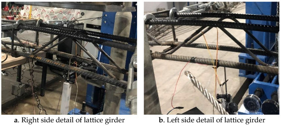
Figure 11.
Loading failure of steel frame LG-4W-12-1.

Figure 12.
Loading failure of steel frame LG-4W-14-1.
- (2)
- Displacement–load relationship
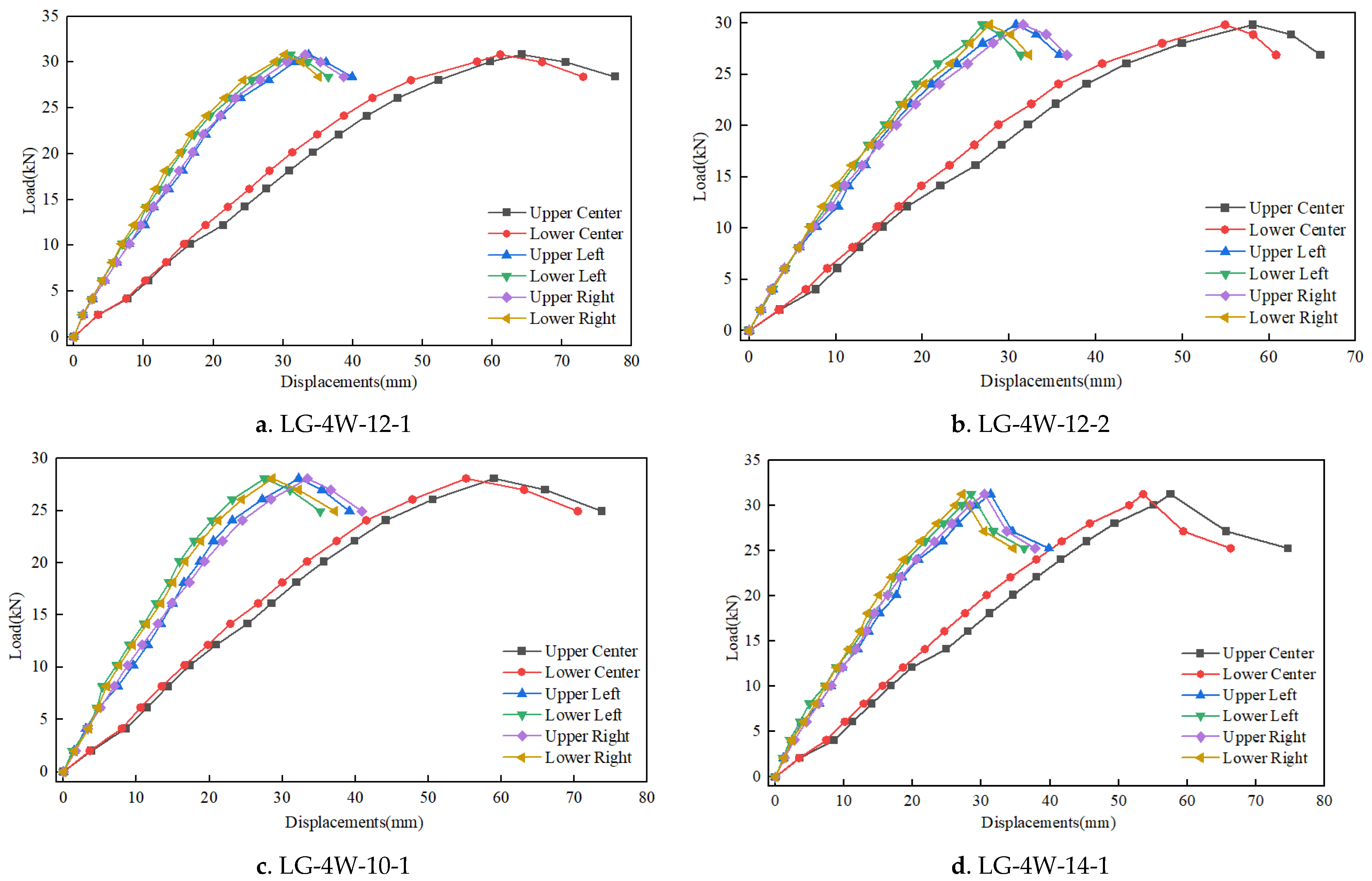
The displacement–load curves of four-bar W-shaped lattice girders are shown in Figure 13. By analyzing the loading process, final failure mode, and displacement–load relationship of each steel frame, the loading deformation can be divided into three main stages.
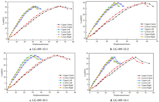
Figure 13.
Load–displacement curves of four-bar W-shaped lattice girder.
- I.
- When the applied load is small, the whole steel frame is in the elastic stage. The displacement of each measuring point is linearly related to the applied load. At this time, the overall stability of the steel frame is very strong, and the stress on each part is relatively uniform.
- II.
- With the continuous increase in load, the upper main bar in the midspan of the steel frame first enters the strengthening stage, and the lower main bar then enters the strengthening stage almost at the same time. The deformation gradually increases but is not obvious. The displacement in the midspan is no longer linear with the applied load, while the displacement in each loading stage begins to increase. The growth rate of the midspan displacement is greater than that of the left and right spans. At this time, the overall stability of the steel frame begins to decrease, and the distribution of stresses is no longer uniform, especially in the midspan area. The original arch shape becomes horizontal, but the steel frame can still withstand the external load.
- III.
- When the load value applied hits the limit, the midspan area is pressed into a horizontal state. The deformation starts to accelerate when the load falls slowly. After reaching the critical value, the displacement begins to increase rapidly. Meanwhile, the steel frame is judged to have been completely destroyed and the loading is terminated. The failure position is in the midspan, but the structure on both sides of the steel frame is still in the elastic stage, and its mechanical properties are not significantly affected.
- (3)
- Comparative analysis of test results
According to the above test results, the load and corresponding displacement of each steel frame at the stage of failure are shown in Table 5, and the steel utilization coefficient of each steel frame calculated is shown in Table 6. Looking at the above test data and the failure mode of the steel frame, the following conclusions can be drawn.
Table 5.
Ultimate load and failure displacement of four-bar W-shaped lattice girder.
Table 6.
Steel utilization coefficient of four-bar W-shaped lattice girder.
- I.
- Through comparison, with the increase in the diameter of the web bar, the ultimate bearing capacity of the steel frame is enhanced, and the steel utilization coefficient also increases by 15% (10–12) and 1.6% (12–14), respectively. The lifting proportion is significantly reduced, indicating that under the current diameter ratio of the upper and lower main bars, the bearing capacity of the steel frame by increasing the diameter of the web bar is close to the peak. When the diameter of the main bar of the four-bar W-shaped lattice girder is 22 mm, the diameter of the web bar is set at 12 mm, which is more reasonable.
- II.
- During the loading process, the main bar of the four-bar W-shaped lattice girder with a 10 mm web bar yields first, and the displacement difference between the upper and lower main bars is larger than that of the other lattice girders. And the steel utilization coefficient of this lattice girder is lower than that of other lattice girders, indicating that the reinforcement of the lattice girder is not reasonable and the strength of the web bar is not enough, which destroys the steel frame in advance.
- III.
- In the test, the upper and lower main bars of all steel frames yield successively, indicating that the diameter ratio of the upper and lower main bars is reasonable. This kind of design scheme can be used for a reference in future designs.
3.3. Four-Bar Double 8-Shaped Lattice Girder
- (1)
- Failure mode
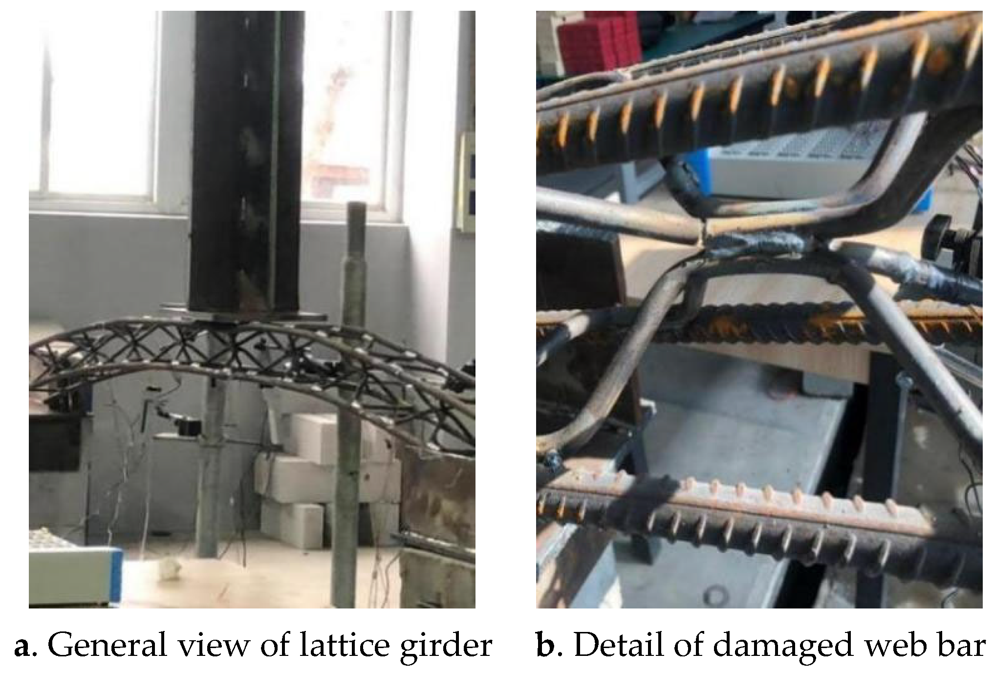
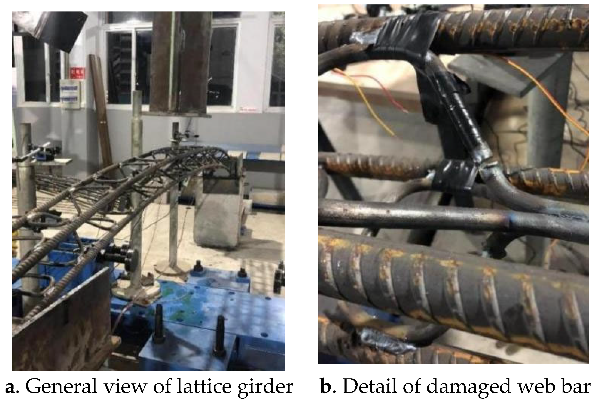
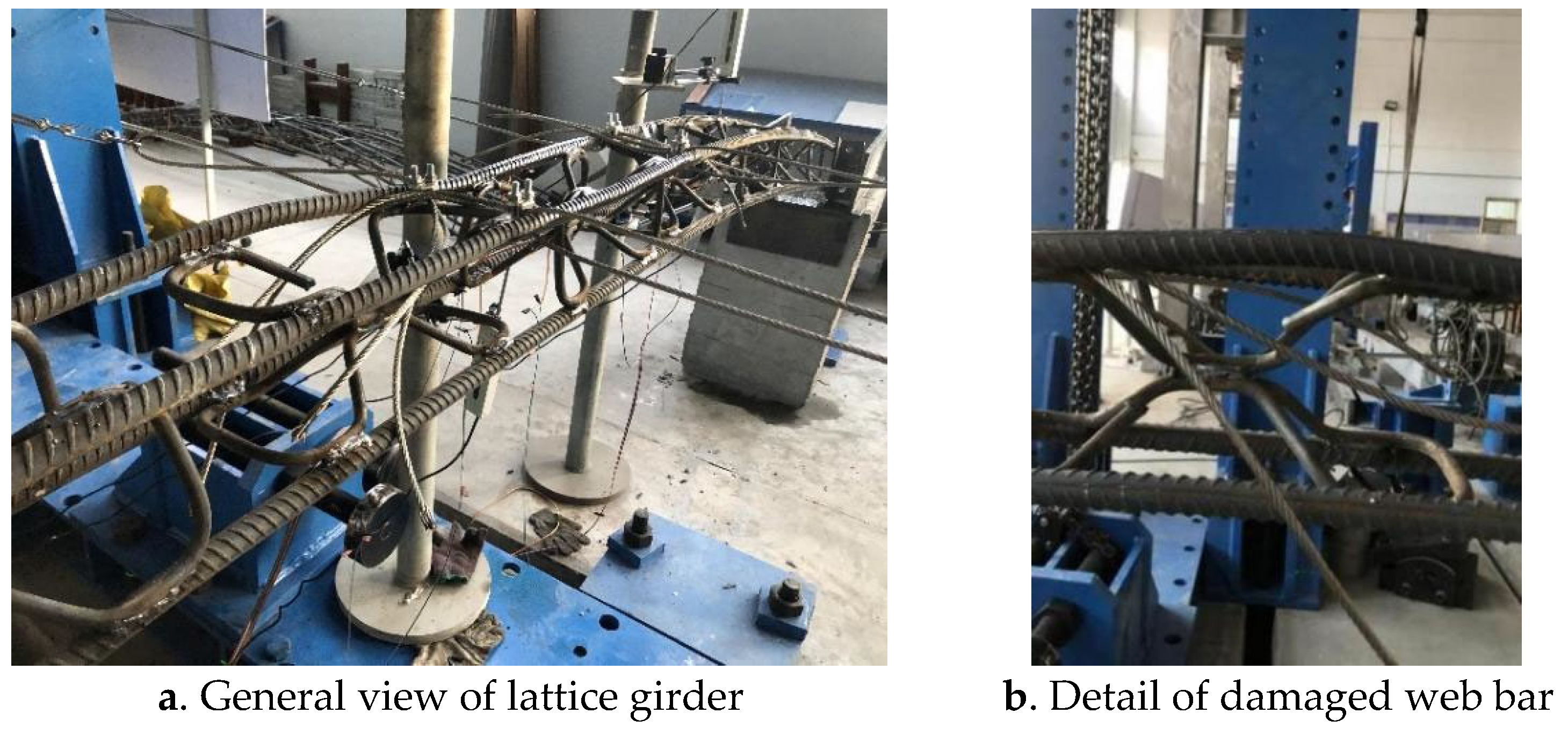
It can be seen from the test results that the failure modes of the four-bar double 8-shaped lattice girders with different web bar diameters and laying types are basically the same. As shown in Figure 14, Figure 15 and Figure 16, during the loading process, the upper main bar in the midspan of the steel frame gradually yields with the gradual increase in the load. After the yield of the upper main bar, the lower main bar soon enters the yield stage, while the spacing between the two bars appears to be more obviously reduced. With the obvious yield deformation of the upper and lower main bars, the midspan area of the steel frame bends downward and changes from the original arched shape to the horizontal shape. With the continuous increase in displacement, shear failure appears on the web bar of the steel frame, and a loud noise is produced. After unloading, it is obvious that the whole midspan is depressed downward and the upper and lower main bars are almost horizontal, and the failure point of the web bar can also be observed.
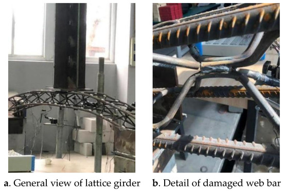
Figure 14.
Loading failure of steel frame LG-4B-22-1.

Figure 15.
Loading failure of steel frame LG-4B-25-1.
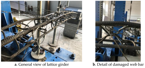
Figure 16.
Loading failure of steel frame LG-ZH4B-22-1.
- (2)
- Displacement–load relationship
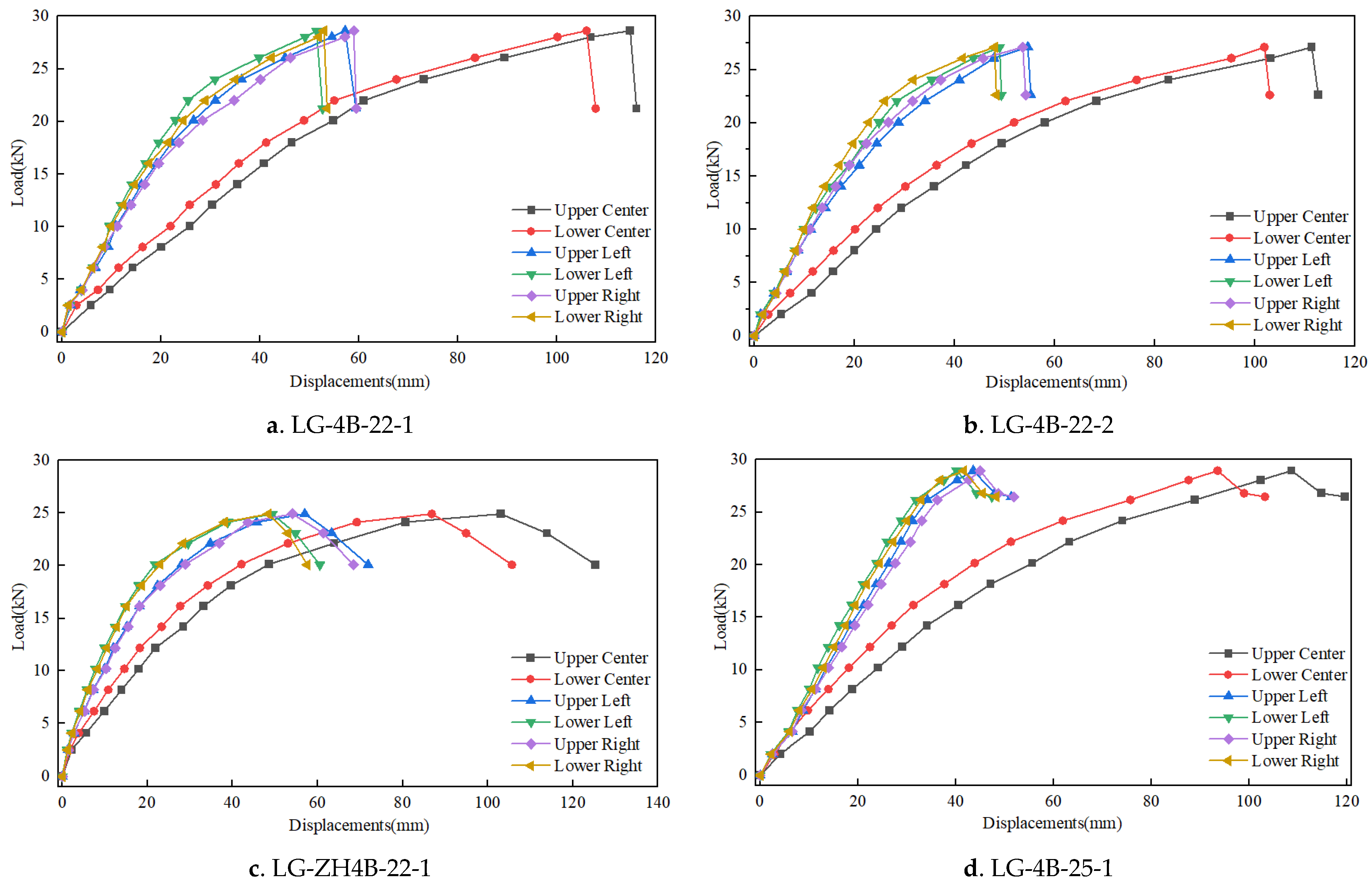
The displacement–load curves of four-bar double 8-shaped lattice girders are shown in Figure 17. By analyzing the loading process, final failure mode, and displacement–load relationship of each steel frame, the loading deformation can be divided into three main stages.
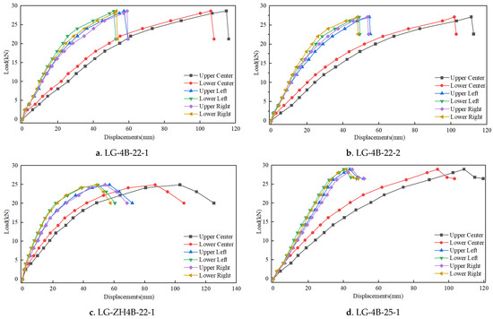
Figure 17.
Load–displacement curves of four-bar double 8-shaped lattice girder.
- I.
- When the applied load is small, the whole steel frame is in the elastic stage. The displacement of each measurement point is linearly related to the applied load. At this time, the steel frame is stable, and the stress on each part is relatively uniform.
- II.
- With the continuous increase in load, the upper main bar in the midspan of the steel frame enters the strengthening stage at first, and the lower main bar then enters the strengthening stage almost at the same time. Although the deformation of the whole part gradually increases, the deformation of the web bar is not obvious. The displacement in the midspan is no longer linearly related to the applied load, the displacement in each loading stage starts to increase, and the growth rate of the midspan displacement is greater than that of the left and right spans. At this time, the overall stability of the steel frame begins to decrease, and the stress distribution is no longer uniform, especially in the midspan area, which is turned from the original arching to horizontal, but the steel frame can still withstand the external load.
- III.
- When the applied load reaches the limit, the midspan area is in a depressed state, and the load starts to drop sharply. Accompanied by the shear failure of the web bar, a loud noise can be heard. At this time, the steel frame is judged to be completely destroyed and the loading is terminated. The failure position is in the midspan, part of the structure on both sides of the steel frame also entered the stage of strengthening, and the overall deformation is large.
- (3)
- Comparative analysis of test results
According to the above test results, the load and corresponding displacement of each lattice girder at the failure stage are shown in Table 7, and the steel utilization coefficient of each lattice girder calculated is shown in Table 8. Looking at the above test data and the failure mode of the steel frame, the following conclusions can be drawn.
Table 7.
Ultimate load and failure displacement of four-bar double 8-shaped lattice girder.
Table 8.
Steel utilization coefficient of four-bar double 8-shaped lattice girder.
- I.
- The increase in the diameter of the main bar slightly enhances the ultimate bearing capacity of the steel frame. However, the steel utilization coefficient decreases by 14% (22–25), indicating that the four-bar double 8-shaped lattice girder has reached the optimal ratio of bearing capacity.
- II.
- The longitudinal and transverse webs with 22 mm main reinforcement can carry much smaller loads than the transverse webs with 22 mm main reinforcement. This shows that the arrangement of such webs is irrational. Not only is the force performance poorer, but the processing is also more time-consuming.Under the condition of the same steel consumption and the same diameter of the main bar (22 mm), the ultimate load of the four-bar double 8-shaped lattice girder with a transversely and longitudinally laid web bar is much smaller than that of the four-bar double 8-shaped lattice girder with a transversely laid web bar, indicating that the layout of the longitudinal and transverse web bar is unreasonable, the mechanical performance is poor, and the processing is more time-consuming.
- III.
- Shear failure occurred in the web bar of all steel frames, which indicates that the reinforcement of the steel frame is irrational. The strength of the web bar is not strong enough or the quality of the automatically machined welded joints does not meet the standard, which makes the steel frame damaged in advance.
- IV.
- In the test, the upper and lower main bars of all steel frames yielded successively. This shows that the diameter ratio of the upper and lower main bars is reasonable, and this kind of design scheme can be used as a reference in future designs.
3.4. I-Shaped Steel Rib
- (1)
- Failure mode
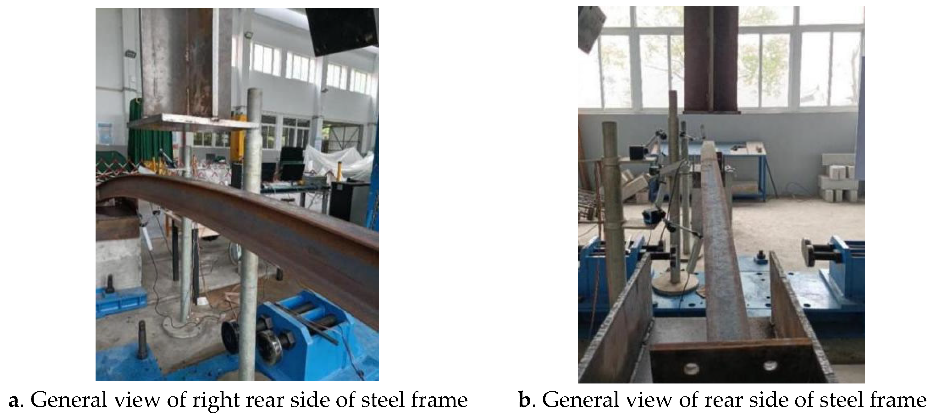
As shown in Figure 18, during the loading process of the I-shaped steel rib, with the gradual increase in load, the midspan area gradually yields and bends downward, changing from the original arch shape to the horizontal shape. With the continuous increase in deformation, the bearing capacity of the steel frame gradually decreases until the I-shaped steel rib overturns and loses bearing capacity.
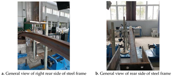
Figure 18.
Loading failure of steel frame XG-1.
- (2)
- Displacement–load relationship
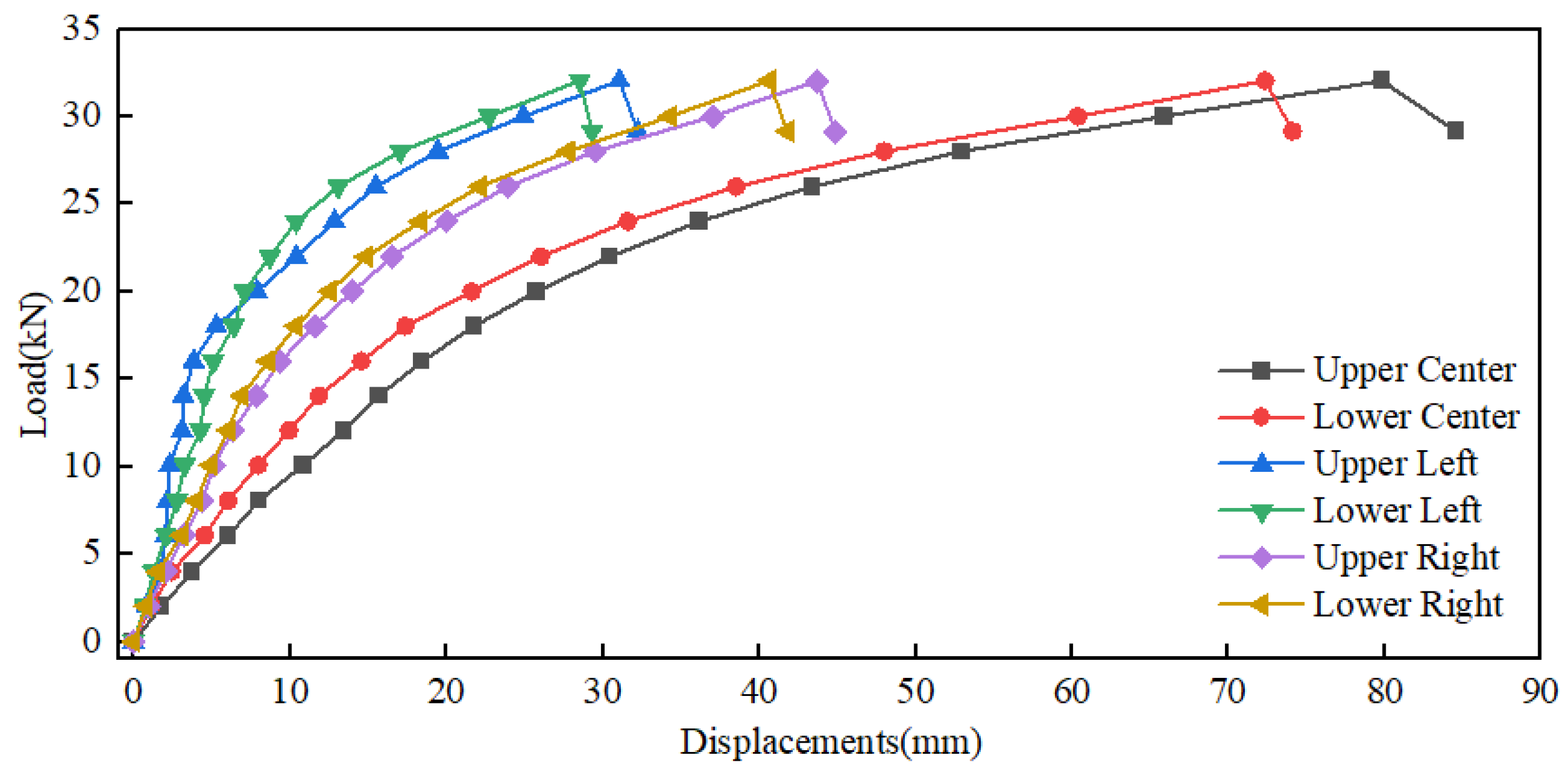
The displacement–load curve of the I-shaped steel rib is shown in Figure 19. The loads and corresponding displacements of the steel rib at the failure stage are shown in Table 9. By calculating the above test results, the steel utilization coefficient of the steel rib can be obtained, as detailed in Table 10. By analyzing the loading process, final failure mode, and displacement–load relationship of the steel rib, the loading deformation can be divided into three main stages.
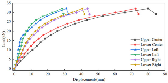
Figure 19.
Load–displacement curves of I-shaped steel rib.
Table 9.
Ultimate load and failure displacement of I-shaped steel rib.
Table 10.
Steel utilization coefficient of I-shaped steel rib.
- I.
- When the applied load is small, the whole steel frame is in the elastic stage, and the displacement of each measuring point is linearly related to the applied load. At this time, the overall stability of the steel frame is very strong and the stress on each part is relatively uniform.
- II.
- As the load increases, the midspan of the steel frame first enters the strengthening stage, and the deformation gradually increases. The midspan displacement is no longer linear with the applied load, the displacement in each loading stage begins to increase, and the growth rate of the midspan displacement is greater than that of the left and right spans. At this time, the overall stability of the steel frame begins to weaken and the stress distributions are no longer uniform, especially in the midspan area where the original arch becomes horizontal, but the steel frame can still withstand the external load.
- III.
- When the applied load reaches the limit, the midspan area is in a state of inclination toward the side, the load starts to drop sharply, and the loading is terminated. The failure position of the steel frame is in the midspan, there is a tendency for torsional failure, and the overall deformation is large.
4. Discussion
As shown in Table 11, according to the above test results, the steel utilization coefficients of the various types of steel frames were ranked from large to small as the I-shaped steel rib, three-bar W-shaped lattice girder, four-bar W-shaped lattice girder, and four-bar double 8-shaped lattice girder. Compared with the lattice girder, the ultimate bearing capacity of the steel rib structure is larger, and the initial stiffness is larger. After construction, the steel rib can immediately support the surrounding rock, bear the surrounding rock pressure in time, and play a more important role in controlling the surrounding rock deformation. Therefore, it is more suitable for highway tunnels with grade V surrounding rock, which have large early deformation. The contact between the surrounding rock, whose strength grade is IV or better, and the lattice girders is more even and stable, so that the surrounding rock can give full play to its self-supporting capacity. Compared with the steel rib, the lattice girder is more closely combined with the concrete after shotcreting, sustaining long-term cooperation. So far, the four-bar W-shaped lattice girder is commonly used in Chinese highway tunnel engineering. According to the research in this paper, the comprehensive performance of the three-bar W-shaped lattice girder is better under ideal loading conditions, so it is recommended to adopt the three-bar W-shaped lattice girder in the future.
Table 11.
Comparison of four arch designs for the tunnel.
Four kinds of steel frames are designed for a standard highway tunnel in China (see Table 11). We compared the weight of the whole frame of four types of arch frames, and assessed them under the condition of ensuring the safety of the tunnel structure. Due to the high steel utilization coefficient of the three-bar W-shaped lattice girder, a single arch saves about 107 kg of steel compared with the commonly used four-bar W-shaped lattice girder. According to the current annual new highway tunnel mileage of 100 km, 30% of the tunnel length shall be supported by the steel frame of the lattice girder due to the surrounding conditions. Based on the spacing of steel frames of 1 m, if the four-bar W-shaped lattice girder is replaced by the three-bar W-shaped lattice girder, the construction cost can be saved about CNY 13 million (steel price is calculated at 4000 CNY/ton). In summary, the three-bar W-shaped lattice girder is a form of steel frame that can be widely promoted and applied.
5. Conclusions
In this paper, multiple groups of destructive loading tests were carried out on a three-bar W-shaped lattice girder, four-bar W-shaped lattice girder, four-bar double 8-shaped lattice girder, and I-shaped steel rib, using an indoor test platform. The following main conclusions were drawn from the analysis of the loading process, failure mode, and ultimate bearing capacity of the steel frames.
- (1)
- A set of laboratory loading and measurement platforms for testing the steel arch of tunnel primary lining was developed, and the steel utilization coefficient that can scientifically evaluate the bearing efficiency of various steel arches was proposed. The coefficient provides a simple and reasonable quantitative method to evaluate the mechanical performance and economy of various types of tunnel lining structures.
- (2)
- The steel utilization coefficient of the I-shaped steel rib is higher than that of all kinds of lattice girders. When the shotcrete is not sprayed or solidified, the bare arch bears most of the surrounding rock pressure. However, considering that the combination of the I-shaped steel rib and concrete is not as good as that of a lattice girder, it is preferable to adopt a lattice girder in the case of small early deformation of surrounding rock.
- (3)
- For the lattice girders, the test results show that the diameter ratio of the main reinforcement and the abdominal reinforcement of the grille should be optimized, so as to make the force distribution of the main reinforcement and the abdominal reinforcement more uniform. The diameter ratio of the upper main bar to the lower main bar should be increased, and the diameter of the web bar can be appropriately increased. The steel frame with horizontally laid web bars has better mechanical performance under the same steel consumption.
- (4)
- Under the condition of the optimal combination of the diameter of the main bar and the web bar, the steel utilization coefficients of the three types of lattice girders are, in descending order, three-bar W-shaped lattice girder, four-bar W-shaped lattice girder, and four-bar double 8-shaped lattice girder. The steel utilization coefficient of the three-bar W-shaped lattice girder is the largest, and its steel consumption is the most economical under the same load-bearing capacity requirements. The three-bar W-shaped lattice girder is a form of steel frame that is worth applying and popularizing in highway tunnel primary lining.
Author Contributions
Conceptualization, W.L.; Methodology, Y.Z. (Yizhou Zhuang) and H.G.; Software, C.X.; Validation, Y.Z.(Yunhui Zheng); Formal analysis, Y.Z.(Yunhui Zheng); Investigation, Y.F.; Data curation, C.L.; Writing—original draft, C.L. and Y.L.; Writing—review & editing, G.Z.; Supervision, Y.Z. (Yizhou Zhuang); Project administration, H.G. All authors have read and agreed to the published version of the manuscript.
Funding
The paper is supported by the Science and Technology Plan Project of Zhejiang Communications Investment Group Co., Ltd. (Grant No. 201815), Science and Technology Plan Project of Zhejiang Provincial Department of Transportation (Grant No. 2020005), and Science and Technology Demonstration Project of Zhejiang Provincial Department of Transportation (Grant No. 2021070).
Data Availability Statement
The data that support the findings of this study are available from the corresponding author upon reasonable request.
Conflicts of Interest
Authors Changjun Li, Yuquan Lu, Yunhui Zheng, Wenhao Li, Hongyu Guo and Yuchao Fang were employed by the company Zhejiang Institute of Communications Co., Ltd. The remaining authors declare that the research was conducted in the absence of any commercial or financial relationships that could be construed as a potential conflict of interest.
References
- Li, J.; Tan, Z. On the Interaction Mechanism of the Primary Support and Rock Mass in a Loess Tunnel with a Large Section. Mod. Tunn. Technol. 2013, 50, 79–86. [Google Scholar]
- Tan, Z.; Yu, Y.; Wang, M.; Wang, M. Comparative tests on section steel and steel grid for loess tunnels with large section. Chin. J. Geotech. Eng. 2009, 31, 628–633. [Google Scholar]
- Zhang, X. Optimization and Application of Support Scheme for Tunnel with High In-situ Stress in Ningchan. E3S Web Conf. 2021, 248, 03004. [Google Scholar]
- Liu, W.; Chen, J.; Luo, Y.; Chen, L.; Shi, Z.; Wu, Y. Deformation Behaviors and Mechanical Mechanisms of Double Primary Linings for Large-Span Tunnels in Squeezing Rock. Rock Mech. Rock Eng. 2021, 54, 2291–2310. [Google Scholar] [CrossRef]
- Wong, L.; Fang, Q.; Zhang, D. Mechanical analysis of circular tunnels supported by steel sets embedded in primary linings. Tunn. Undergr. Space Technol. Inc. Trenchless Technol. Res. 2013, 37, 80–88. [Google Scholar] [CrossRef]
- Smaniotto, S.; Neuner, M.; Cordes, T.; Hofstetter, G. Experimental study of a wet mix shotcrete for primary tunnel linings—Part II: Shrinkage, creep, thermal and hygral behavior of shotcrete. Eng. Fract. Mech. 2022, 267, 108410. [Google Scholar] [CrossRef]
- Wang, Z.; Cai, Y.; Fang, Y.; Lai, J.; Han, H.; Liu, J.; Lei, H.; Kong, X. Local buckling characteristic of hollow π-type steel-concrete composite support in hilly-gully region of loess tunnel. Eng. Fail. Anal. 2022, 143, 106828. [Google Scholar] [CrossRef]
- Embaby, K.; Naggar, M.; Sharnouby, M.E. Performance of large-span arched soil–steel structures under soil loading. Thin-Walled Struct. 2022, 172, 108884. [Google Scholar] [CrossRef]
- Zhang, X.; Su, J.; Xu, Y.; Min, B. Experimental and numerical investigation the effects of insufficient concrete thickness on the damage behaviour of multi-arch tunnels. Structures 2021, 33, 2628–2638. [Google Scholar] [CrossRef]
- Liu, K.; Liu, B. Intelligent information-based construction in tunnel engineering based on the GA and CCGPR coupled algorithm. Tunn. Undergr. Space Technol. 2019, 88, 113–128. [Google Scholar] [CrossRef]
- Liu, Y.; Yao, C.; Luo, W.; He, C.; Sun, M.; Wang, E.; Yuan, F. Deformations and damages of tunnels subjected to strike-slip faulting: Effects of tectonic stress and cross-sectional shape. Eng. Fail. Anal. 2024, 160, 108159. [Google Scholar] [CrossRef]
- Zhou, Y.; Lai, H.; Liu, Y.; Hong, Q.; Li, Z. Analysis and treatments of primary support failure in large-span tunnel under a soft-hard interbedded surrounding rock mass. Eng. Fail. Anal. 2024, 156, 107755. [Google Scholar] [CrossRef]
- Kim, S.; Han, T.; Baek, J.; Kang, Y. Evaluation of the Structural Performance of the Tetragonal Lattice Girder. Int. J. Steel Struct. 2012, 13, 31–47. [Google Scholar] [CrossRef]
- Song, Y.; Huang, M.; Zhang, X.; Li, Z.; Peng, X. Experimental and numerical investigation on bearing capacity of circumferential joint of new spatial steel tubular grid arch in mined tunnel. Symmetry 2020, 12, 2065. [Google Scholar] [CrossRef]
- Li, G.; Yu, C.; Wang, X.; Ding, W.; Zhang, Q. Parameter optimization of corrugated steel initial support structure of mountain tunnel based on sensitivity analysis. IOP Conf. Ser. Mater. Sci. Eng. 2020, 741, 012077. [Google Scholar] [CrossRef]
- Xu, J.; Li, N. Influence of continuous rainfall on surrounding rock-initial support system of shallow decomposed-rock tunnel. Environ. Earth Sci. 2010, 61, 1751–1759. [Google Scholar] [CrossRef]
- Zhang, D.L.; Chen, F.B.; Fang, Q. Study on mechanical characteristics and applicability of primary lining used in tunnel. Eng. Mech. 2014, 31, 78–84. [Google Scholar]
- Chen, J.; Qiu, W.; Zhao, X.; Rai, P.; Ai, X.; Wang, H. Experimental and numerical investigation on overbreak control considering the influence of initial support in tunnels. Tunn. Undergr. Space Technol. 2021, 115, 104017. [Google Scholar] [CrossRef]
- Zhao, Y.; Liu, J.; Tian, S. Experimental study of mechanical characteristics of support system for weak surrounding rock of deep tunnels. Chin. J. Rock Mech. Eng. 2011, 30, 1663–1670. [Google Scholar]
- Song, C.; He, W.; Fei, M. Study on mechanical characteristics of support system for Shallow-buried Single-Arch subway station in rock stratum. Tunn. Undergr. Space Technol. 2022, 124, 104447. [Google Scholar] [CrossRef]
- Han, K. Experimental study on the application of heat-treated high-strength lattice girder in tunnel engineering. Symmetry 2019, 11, 1007. [Google Scholar] [CrossRef]
- Nomikos, P.P.; Sofianos, A.I.; Sakkas, K.M.; Choumanidis, D.; Delendas, S. Nonlinear simulation of lattice girder segment tests. Tunn. Undergr. Space Technol. 2013, 38, 180–188. [Google Scholar] [CrossRef]
- Qu, H.; Zhu, H.; Huang, C.; Yan, Z.; Cai, Y.; Ding, W. Study on Selection of Section-steel and Grid-steel in Primary Support System of Tunnel. Chin. J. Undergr. Space Eng. 2007, 3, 258–262. [Google Scholar]


Disclaimer/Publisher’s Note: The statements, opinions and data contained in all publications are solely those of the individual author(s) and contributor(s) and not of MDPI and/or the editor(s). MDPI and/or the editor(s) disclaim responsibility for any injury to people or property resulting from any ideas, methods, instructions or products referred to in the content. |
© 2024 by the authors. Licensee MDPI, Basel, Switzerland. This article is an open access article distributed under the terms and conditions of the Creative Commons Attribution (CC BY) license (https://creativecommons.org/licenses/by/4.0/).