Article

Research on the Mechanism and Application of High Pre-Tension on the Crack-Arresting Effect of Rockbolt Anchorage

1
School of Mining Engineering, Anhui University of Science and Technology, Huainan 232001, China
2
School of Mines, China University of Mining and Technology, Xuzhou 221116, China
*
Author to whom correspondence should be addressed.
Buildings 2024, 14(8), 2584; https://doi.org/10.3390/buildings14082584
Submission received: 22 July 2024 / Revised: 19 August 2024 / Accepted: 20 August 2024 / Published: 22 August 2024
(This article belongs to the Special Issue Structural Analysis of Underground Space Construction)

Abstract

:
In order to investigate the effect of pre-tension on the anchoring and crack-arresting effect of rockbolts, a theoretical model of stress intensity factor at the crack tip in anchored surrounding rock was established using fracture mechanics theory. An expression for the difference in stress intensity factor due to axial force on the rockbolt was derived, exploring the influence of pre-tension on the stress intensity factor of cracks. A numerical model of anchored crack specimens was developed using UDEC (V6.0) software to simulate and analyze the mechanical performance and damage characteristics of specimens anchored with different pre-tension. The results indicate that the difference in stress intensity factor of cracks is positively correlated with pre-tension. High-pre-tensioned rockbolts can effectively reduce the stress intensity factor of cracks. Prestressed rockbolts can alter the failure mode of rock masses from shear failure along pre-existing cracks to tensile splitting failure. The application of high pre-tension significantly enhances the strength of the rock mass, reducing both the damage degree and the number of internal cracks. After anchoring with high-pre-tensioned rockbolts, the peak strength and elastic modulus of the crack specimens increased by 22.5% and 31.9%, respectively, while damage degree decreased by 17.4%, the number of shear cracks decreased by 22.6%, and the number of tensile cracks decreased by 42.9%. The pre-tensioned rockbolt method proposed in this study was applied to the support of roadway widening. Field monitoring data indicated that the axial force of the rockbolts in the test section generally exceeded 60 kN, effectively controlling the deformation of the roadway surrounding the rock. The convergence of the two sides decreased by 22%, and borehole inspections showed a significant reduction in internal cracks. The research results provide a theoretical basis for controlling the discontinuous deformation of deep broken surrounding rock roadways.

1. Introduction

As one of the crucial reinforcement techniques in underground engineering, rockbolt support has been widely applied in the control of surrounding rock in coal mine roadways in China [1,2,3]. High-prestressed, high-strength, and high-elongation rockbolt support is an effective method for controlling the deformation of surrounding rock. By actively applying high pre-tension, a high-strength prestressed rockbolt can fully mobilize the inherent stability of the surrounding rock [4,5]. With the increasing depth of coal resource extraction, the support objects in deep roadways are often fractured rock masses containing cracks. The continuous propagation of these internal cracks in the surrounding rock is a major cause of anchor instability [6]. Therefore, it is necessary to conduct research on the crack-arresting effect of high-pre-tensioned rockbolts to effectively control the discontinuous deformation of fractured surrounding rocks.
The instability of fractured rock masses is primarily driven by slippage along weak planes, and rockbolts exert their anchoring effect through mechanisms such as toughening, slip resistance, and axial compression [7,8]. Scholars have conducted extensive research on the mechanical properties of bolted jointed rock masses and the crack-arresting mechanisms of rockbolts. Liu et al. [9] and Liu et al. [10,11] found that high-pre-tensioned rockbolts can significantly increase the cohesion and internal friction angle of joint surfaces, effectively enhancing the shear stiffness of jointed rock masses and inhibiting rock deformation. Zhou et al. [12] found that as the angle of rockbolts changes, the ultimate tensile strength of the bolted body first increases and then decreases. Wang et al. [13] concluded that full-length anchoring and extended anchoring can effectively control the deformation of jointed surrounding rock in roadways. Shi et al. [14] posited that the stability of the support structure is determined by the bond damage at the rockbolt–rock interface. Based on the uniaxial compression and CT scan results of bolted rock samples, Teng et al. [15] concluded that the crack-arresting effect of rockbolts is due to the weakening, cutting, and arresting of cracks within the bolted zone. Experimental results of Zhao et al. [16] indicated that rockbolts can enhance the cracking strength, elastic modulus, and peak strain ratio of jointed rocks. The simulation analysis results of Wang et al. [17] indicated that prestressed rockbolts crossing joints can effectively increase the compressive stress on crack surfaces. Wu et al. [18] believed that the reinforcement mechanism of rockbolts can be divided into two aspects: one is to share the load, and the other is to inhibit crack propagation. Zu et al. [19] discovered that high-pre-tensioned rockbolts could still exert crack-arresting effects under impact loads, significantly enhancing the fracture toughness of rock masses and delaying the initiation and development of cracks. Zhang et al. [20] concluded that the axial force of the rockbolts, combined with the expansive stress of the grout, acts synergistically on the fractured rock mass, thereby improving its stress situation. Li and Ge [21,22] identified the “axial compression” and “dowel” effects as the primary mechanisms by which rockbolts control internal cracks in rock masses. Through acoustic emission and stress monitoring in uniaxial failure tests, Wang et al. [23] demonstrated that within the effective anchoring range, rockbolts can delay the initiation of primary cracks and increase the strength of cracked specimens. Yuan et al. [24] simulated and analyzed rockbolts from a microscopic perspective, concluding that rockbolts increase the cohesion of cracks within rock masses. Zhou et al. [25] found that prestressed rockbolts not only enhance the mechanical properties of rock masses, but also restrict crack formation and alter crack propagation modes. Chen et al. [26] and Wu et al. [27] discovered that rockbolts could effectively reduce the number of cracks within the fill body and increase its load-bearing capacity.
Based on the previous research conclusions, it can be found that rockbolts can delay the initiation time and development speed of cracks, reduce the number of cracks in the rock body, and improve the shear stiffness and compressive strength of the rock mass by increasing parameters such as crack cohesion, internal friction angle, and initiation strength in the anchorage zone, thereby achieving stability of the fractured rock mass. However, the crack-arresting effect of rockbolts on cracks in rock masses is the result of multiple factors, such as pre-tension, anchoring method, anchoring zone range, and rockbolts–rock interface damage. The mechanism by which pre-tension affects the crack-arresting effect of rockbolts is still unclear. Therefore, this article conducts relevant research on the factor of pre-tension. Firstly, based on the theory of fracture mechanics, a theoretical model of the stress intensity factor at the crack tip of the anchored rock mass in deep roadways was established. The relationship between the pre-tension and the stress intensity factor of the crack was clarified, and it was proven that high-pre-tensioned rockbolts can suppress the initiation of internal cracks in the rock mass. Subsequently, numerical simulation methods were used to study the mechanical and damage characteristics of the anchorage body, analyzing the strength, number of cracks, and degree in damage of the anchorage body under different pre-tension, and elucidating the mechanism by which pre-tension affects the crack-arresting effect of rockbolts. Finally, effective reinforcement methods were proposed based on the research results and actual on-site conditions.

2. Engineering Profile

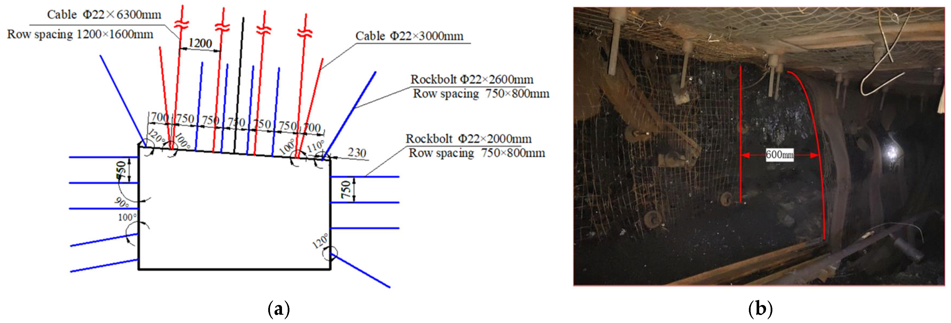
2.1. Engineering Background

The Ji-15-23090 headgate of Pingmei No. 4 Mine is located in the Ji-15 coal seam at a depth of 900 m. The coal seam exhibits blocky structures with an average thickness of 1.5 m and an average dip of 9.6°. The immediate roof consists of a composite roof composed of 4.5 m of fine sandstone and 0.25 m of Ji-15 coal, while the main roof is 3.0 m of fine sandy mudstone. The immediate floor comprises 1.6 m of mudstone, and the main floor is 7.5 m of fine sandy mudstone.
The roadway is driven along the roof of the coal seam, with a net width of 5.4 m and a height of 3.4 m, utilizing anchor and mesh support. The specifications for the side rockbolts are Φ22 × 2400 mm, with five rockbolts in the upper side and four rockbolts in the lower side, spaced at intervals of 750 × 800 mm. The rockbolts are torqued to 300 N·m. The support parameters are illustrated in Figure 1a, and the field deformations are depicted in Figure 1b.

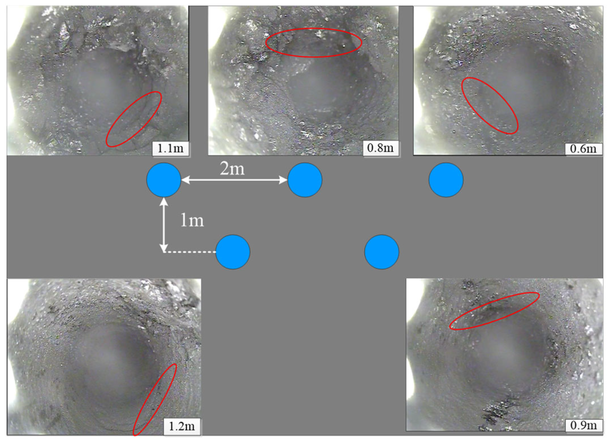
2.2. Analysis of Peeping Results

During the mining period, influenced by high in situ stress and mining-induced stress at depth, the surrounding rock of the Ji-15-23090 headgate has become fragmented. In order to view the broken surrounding rock of the roadway, boreholes are arranged in the side of the roadway for peeping. Figure 2 shows the arrangement and observation of boreholes. The blue circle in this Figure shows five boreholes, and five photos show the observation of each borehole.
In adjacent boreholes at a depth of approximately 1 m, there are evident circumferential cracks, and the boreholes are considerably fractured. This indicates that at around 1 m depth, there are extensive primary cracks with numerous secondary cracks, leading to significant extrusion of the roadway sides and an average reduction in cross-sectional width to 3.5 m. To ensure safe production, it is necessary to carry out roadway expansion operations.

2.3. Current Issues

From the field observation results, it can be seen that the torque rockbolt has a poor control effect on the deformation of the surrounding rock of the deep roadway due to the low pre-tension, and it is difficult to effectively control the crack development inside the surrounding rock, resulting in the fragmentation of the roadway surrounding the rock and causing the large deformation of the roadway. In response to this situation, this manuscript adopts the methods of theoretical analysis and numerical simulation to carry out relevant research on the crack-arrest effect of high-pre-tension rockbolt, analyzes the mechanism of high-pre-tension affecting the crack-arrest effect of rockbolts, and puts forward effective support methods applied to the field in order to solve the problem of difficult maintenance of deep fractured rock roadways.

3. Theoretical Analysis of Crack-Arresting Effect of Prestressed Rockbolts

Rockbolts primarily inhibit crack propagation through the shear stiffness of the rod and the application of axial force. This study focuses on the axial force of rockbolts, and based on the stress conditions of the surrounding rock in deep roadways and fracture mechanics theory, establishes the theoretical model of the stress intensity factor at the crack tip in anchored surrounding rock, as shown in Figure 3a. This model is used to explore the influence of pre-tension on the crack-arresting effect of rockbolts.

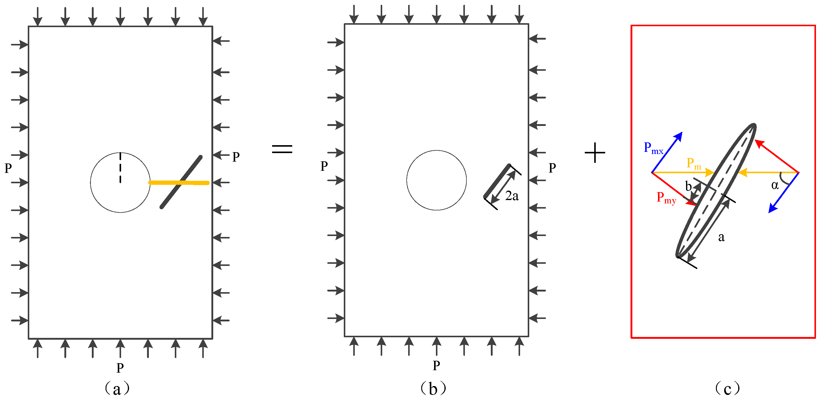
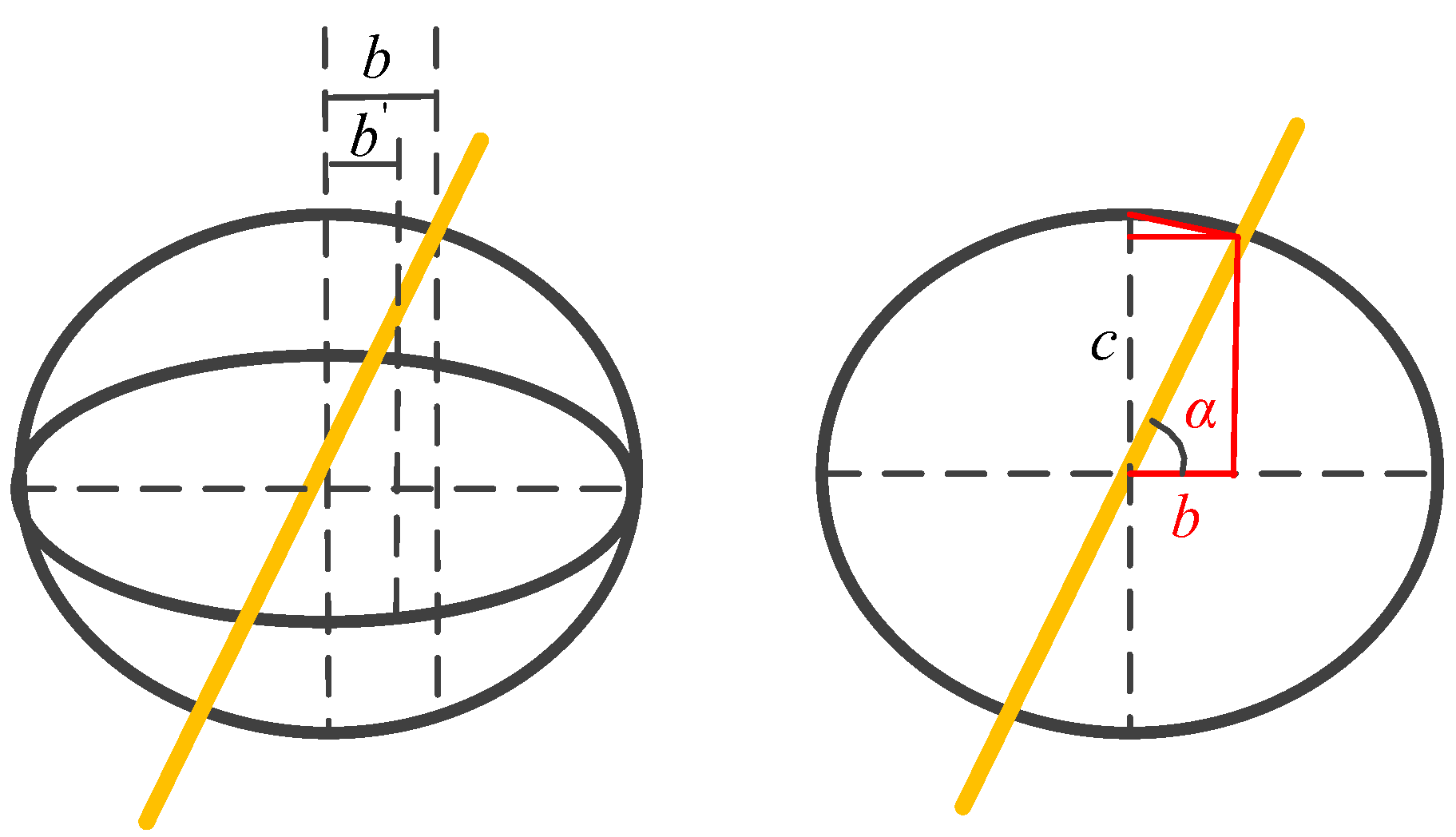
3.1. Stress Intensity Factor Model for Cracks in Anchored Surrounding Rock

Assume the surrounding rock is a homogeneous elastic body under hydrostatic pressure, and ignore the influence of the crack on the stress field distribution [28,29]. The angle between the rockbolt (represented by yellow lines) and the crack is α, and the crack length is 2a. In linear elasticity problems, the stress fields generated by each load can be calculated linearly. Therefore, the model can be decomposed into the in situ stress influence model (Figure 3b) and the rockbolt axial force influence model (Figure 3c).
The intrinsic characteristics of internal cracks in the surrounding rock of deep mine roadways and their stress environment are relatively fixed. The main goal of rockbolt support is to reduce the stress intensity factor of the cracks, thus preventing them from reaching the fracture toughness. In the in situ stress influence model, the calculation of the stress intensity factor follows the problem of crack initiation under compressive and shear stresses. Hence, this study focuses on calculating and analyzing the stress intensity factor in the rockbolt axial force influence model.

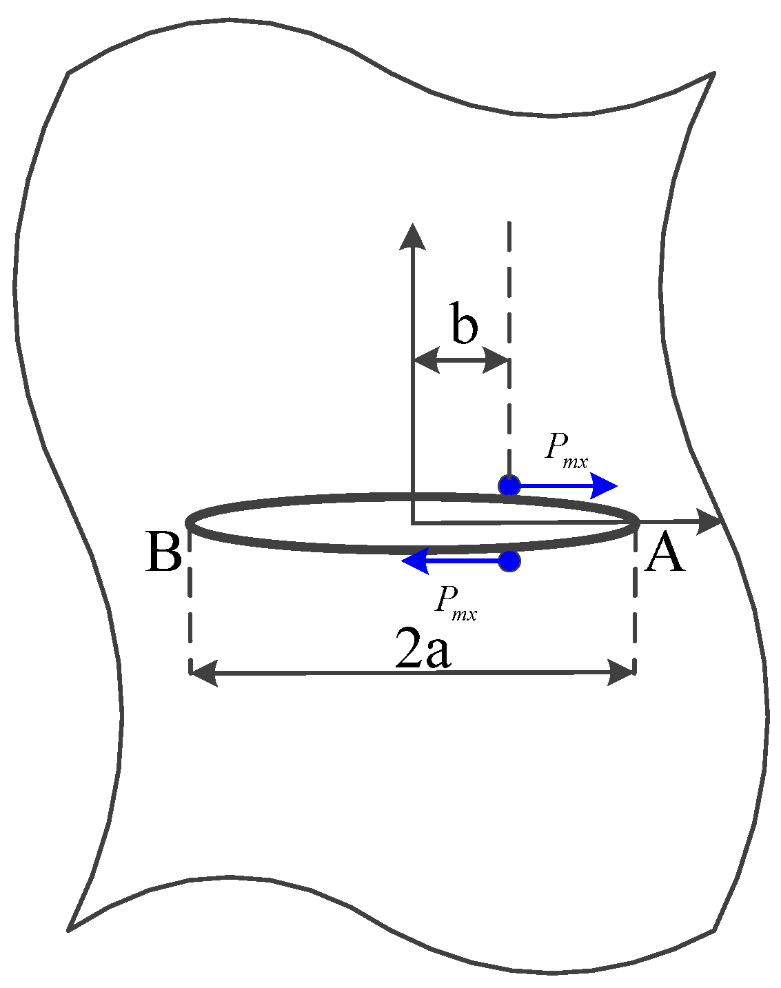
3.2. Expression for the Stress Intensity Factor of Cracks under Axial Force of Rockbolt

Under compressive and shear forces, crack initiation is influenced by the decomposed axial force parallel to its surface. Therefore, the rockbolt axial force influence model can be converted into a model of a crack in an infinite plate subjected to a concentrated shear force (Figure 4).
From Figure 3c, the expression for Pmx is obtained as follows:
P m y = P m sin α P m x = P m cos α
where Pmx is the decomposed force parallel to the crack surface, kN, and Pmy is the decomposed force perpendicular to the crack surface, kN.
In the full-length anchoring method, the relationship between the axial force and the pre-tension of rockbolt is given by [30]:
P m = P t e t z 2 2
where t = 1 1 + μ 3 2 μ d 2 E E m ; Pm is the axial force of rockbolt, kN; Pt is the tensile stress at the end of the rockbolt, kN; μ is the Poisson’s ratio of the rock mass; d is the radius of the rockbolt, mm; E is the elastic modulus of the rock mass, GPa; Em is the elastic modulus of the rockbolt, GPa; and z is the distance from the hole mouth, m.
When the rockbolt does not penetrate the crack perpendicularly and b ≠ 0, the stress intensity factors generated by the concentrated shear stress at both ends of the crack are different. The stress intensity factor at the closer point to the anchor point is selected as the crack-tip stress intensity factor. Based on the Westergard stress function method, the expression for the stress intensity factor at point A is [31]:
K II A = lim z 0 2 π z Z II z = lim z 0 2 π z P m x a 2 b 2 π z + a b z z + 2 a = P m x π a a + b a b
Establishing the geometric relationship between b and the semi-minor axis of the ellipse (c), as shown in Figure 5, and the relationship between the two is as follows:
b = c tan α 1 + tan 2 α
The semi-minor axis of the ellipse (c) is controlled by the normal stress generated on the crack surface by the axial force of the rockbolt (Pmy). Therefore, it is necessary to clarify the relationship between the normal stress on the crack surface (Pmy) and the semi-minor axis (c).
Based on the fracture constituent elements, a model is established, as shown in Figure 6, to analyze the relationship between the normal stress on the crack surface and the crack opening, assuming that the crack is subjected to a uniformly distributed normal stress (Pmy), denoted as σ z , the crack opening is cm, where cm = 2c, and the elastic constants of the crack are λc and Gc. The normal stiffness of the crack is Knc, and the shear stiffness is Ksc.
According to the generalized Hooke’s law:
d σ z d τ x z d τ z y = K n c 0 0 0 K s c 0 0 0 K s c d U z d U x d U y
where K n c = λ c + 2 G c c m U z , K s c = G c c m U z .
From Equation (5), the expression for the deformation of the crack under compression (Uz) is:
U z = c m 1 e σ z λ + 2 G
Therefore, the crack opening after compression ( c m ) is:
c m = c m U z = c m e P m y K n c · c m
Since cm = 2c, the evolution relationship for b can be derived as:
b = 2 c e P m y 2 K n c · c tan α 1 + tan 2 α
Letting Knc = 200 GPa/m, α = 60°, c = 0.1 m, the evolution curve for b can be calculated by substituting these values into Equation (8), as shown in Figure 7. The trend indicates that the anchor point of the rockbolt shifts towards the center of the crack as the pre-tension increases.
Combining Equations (2)–(4) and (8), the expression for the stress intensity factor of the crack under axial force is:
K II m = P t e t z 2 2 cos α π a a 1 + tan 2 α + 2 c e P t e t z 2 2 sin α 2 K n c · c tan α a 1 + tan 2 α 2 c e P t e t z 2 2 sin α 2 K n c · c tan α
According to fracture mechanics theory, under compressive and shear conditions, the damage and failure of the cracked rock mass are still caused by the propagation of tensile cracks [32]. Therefore, the expression for the mode II crack stress intensity factor obtained from Equation (9) needs to be converted into an expression for the mode I crack stress intensity factor:
K I m = 2 3 K II m = 2 3 P t e t z 2 2 cos α π a a 1 + tan 2 α + c e P t e t z 2 2 sin α K n c · c tan α a 1 + tan 2 α c e P t e t z 2 2 sin α K n c · c tan α

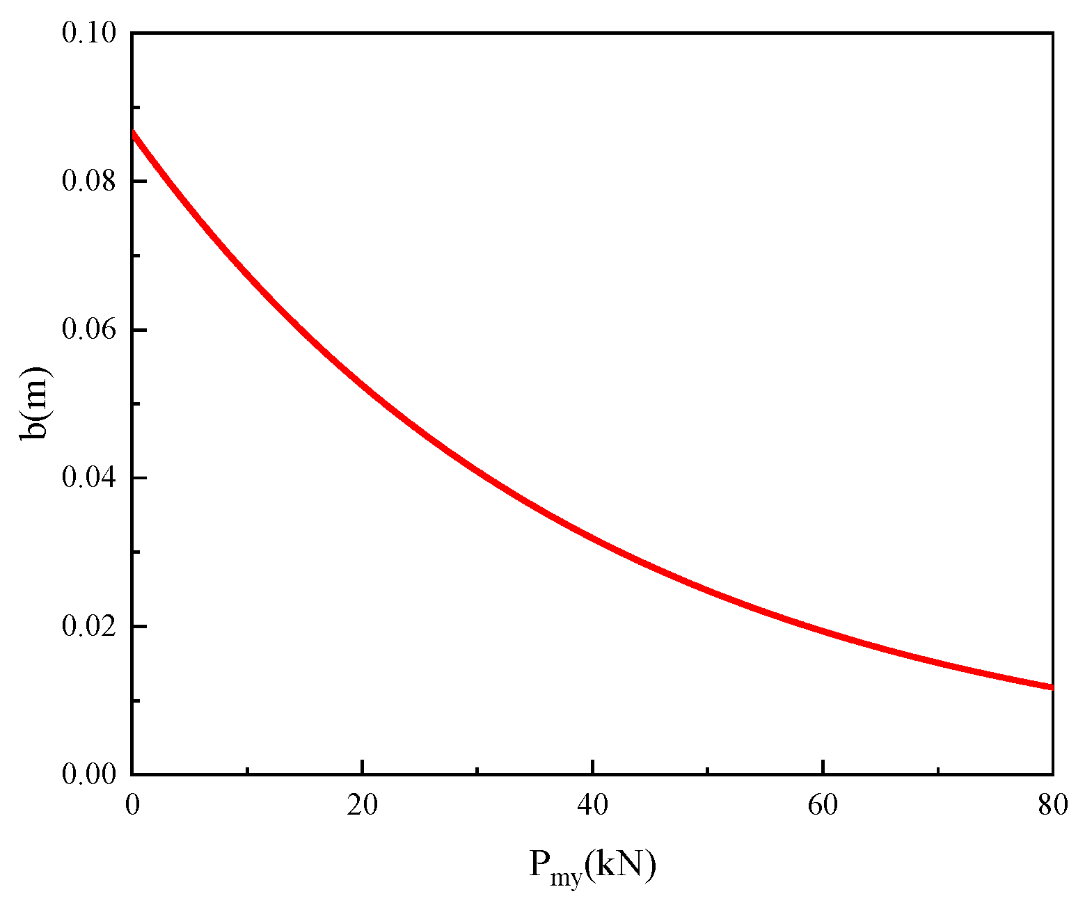
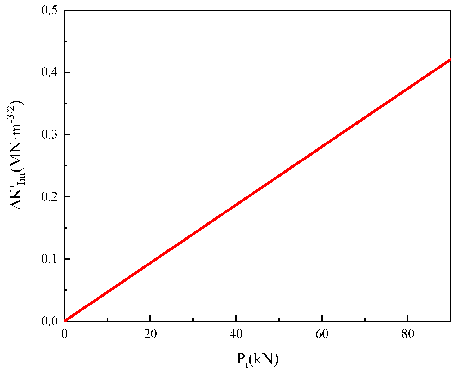
3.3. Influence Mechanism of Pre-Tension on Crack Stress Intensity Factor

The difference in stress intensity factor before and after anchoring represents the stress intensity factor generated by the axial force of the rockbolt, denoted as Δ K I m = K I m . Based on Equation (10), we programmed this relationship in Matlab (V2016) and used the data from Table 1 for calculations, generating the evolution curve of the stress intensity factor difference under the influence of pre-tension, as shown in Figure 8.
From Figure 8, it can be observed that the pre-tension of rockbolt is positively correlated with the stress intensity factor difference. As the pre-tension of rockbolt increases, the stress intensity factor difference also increases. Therefore, high-pre-tensioned rockbolts can effectively reduce the stress intensity factor of cracks, preventing them from reaching the fracture toughness and inhibiting crack initiation and propagation. This conclusion is consistent with the results calculated in the literature [33].
In this section, the theoretical analysis method is used to clarify the relationship between the pre-tension and the crack stress intensity factor, and it is proved that increasing the pre-tension can inhibit the crack initiation inside the rock mass. In the next section, the numerical simulation method will be used to analyze the crack development and mechanical parameter changes in the anchorage body under different pre-tension, and to clarify the crack-arrest mechanism of the high-pre-tension rockbolts.

4. Numerical Analysis of the Crack-Arresting Effect of Prestressed Rockbolts

The above analysis elucidates the evolution trend in the stress intensity factor for cracks under different pre-tension. To further analyze the influence of pre-tension on the crack-arresting effect of rockbolts, this section utilizes the discrete element software UDEC (V6.0) for numerical simulation and analysis.

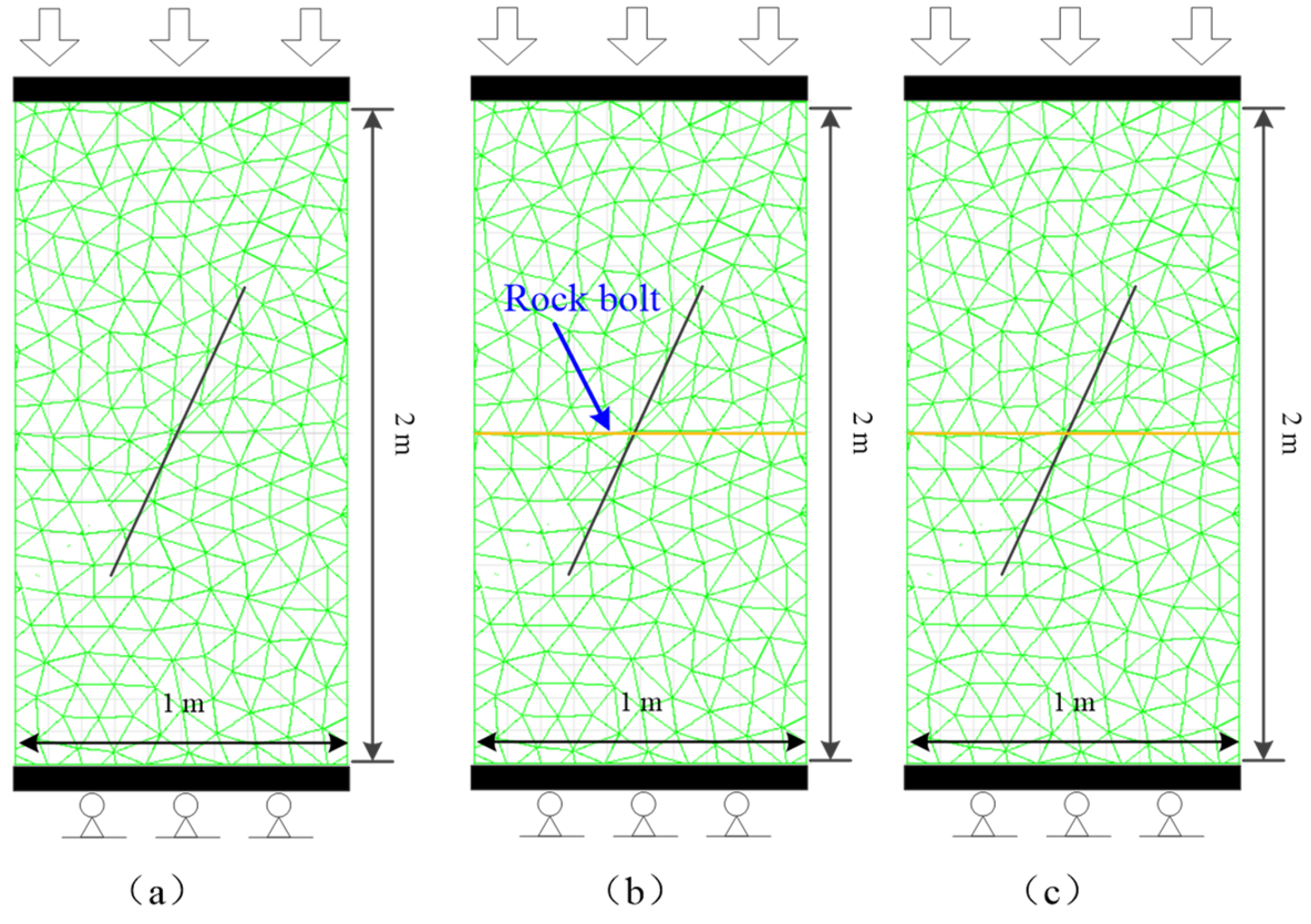
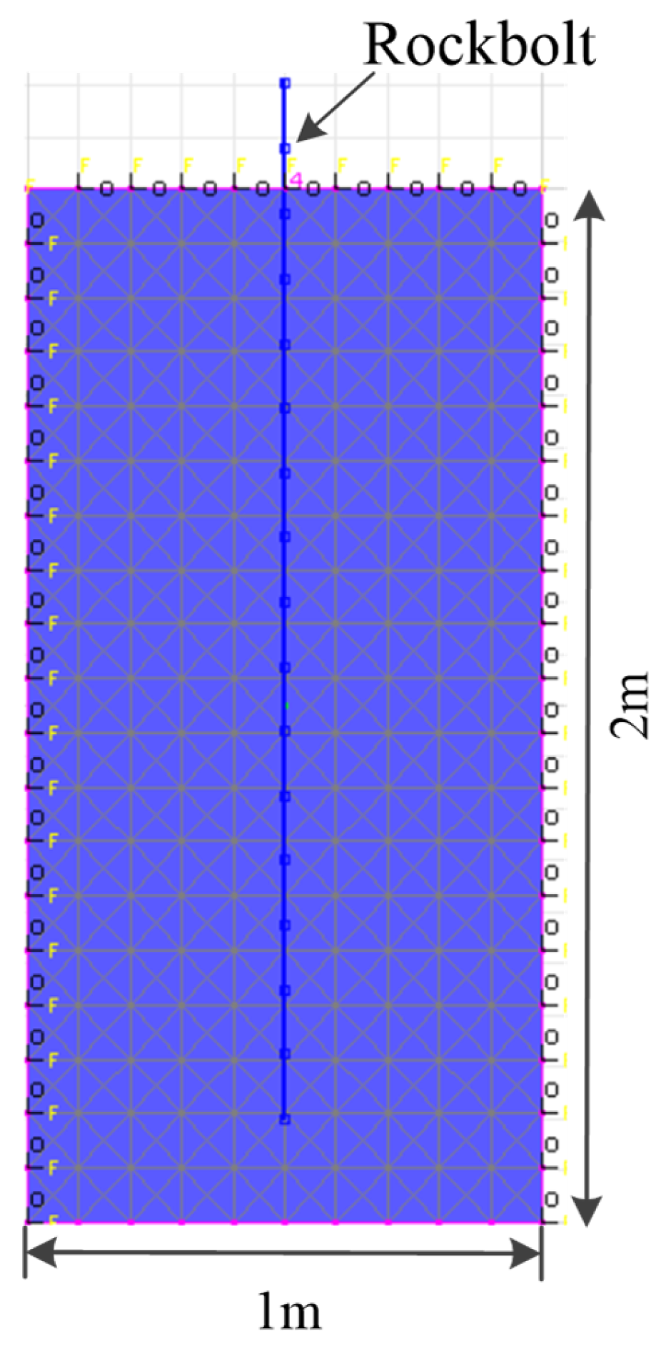
4.1. Establishment of the Numerical Model

To explore the crack-arresting effect of prestressed rockbolts, a model is established, as shown in Figure 9. The dimensions of the model are 1 m in width and 2 m in height. The block and contact surfaces in the model adopt the strain-softening model and the coulomb slip model, respectively. The rockbolt is modeled using the ‘Rockbolt element’, with a full-length anchoring. The simulated rockbolt specifications are Φ22 mm × 2000 mm. The horizontal displacement at the bottom boundary of the model is fixed, and stress is applied to the upper boundary of the model at a loading rate of 0.02 m/s. The crack in the model is located at the center of the rock, with a length of 1.0 m and an angle of 60°. The rockbolt is arranged to pass through the center of the crack, and pre-tension is applied to the rockbolt by loading at the node. Black lines represent cracks, and yellow lines represent rockbolts.
At present, pre-tension is typically applied to rockbolts through torque in underground construction. A pre-tension torque of 300–400 N·m corresponds to a pre-tension of approximately 30–40 kN [34]. This study uses 40 kN, equivalent to a load of 0.105 MPa. For HRB335 left-hand threaded steel rockbolts with a diameter of 22 mm, 70% of the yield strength is approximately 90 kN. This value is used in this study as the high pre-tension application value, which translates to a load of 0.237 MPa. To analyze the crack-arresting effect of rockbolts under different pre-tension, three groups of comparative simulations are set up: uniaxial compression of a crack sample without anchoring, uniaxial compression of a crack sample with low-pre-tensioned rockbolt anchoring, and uniaxial compression of a crack sample with high-pre-tensioned rockbolt anchoring (Table 2).
In the simulation, a FISH language statistical program is independently written to monitor the total length of contact surfaces, and the length and number of shear and tensile cracks within the specimen. The damage degree of the specimen is defined as the ratio of the crack length to the total length of the contact surfaces. The changes in damage degree and crack number before and after anchoring reflect the crack-arresting effect of the rockbolts.
The damage degree of the specimen is as follows:
D = L S + L T L C × 100 %
where LC is the total length of the contact surfaces, LS is the total length of shear cracks, and LT is the total length of tensile cracks.

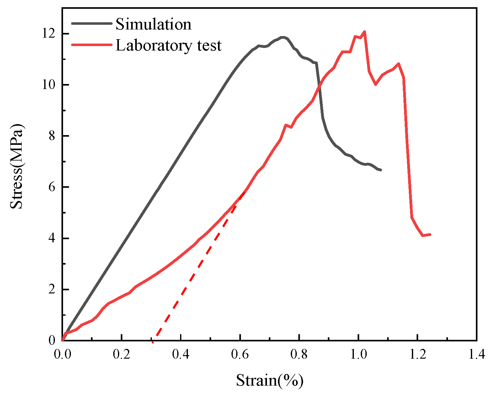
4.2. Calibration of Model Parameters

4.2.1. Calibration of Rock Parameters

A 1 m × 2 m model is established in UDEC for calibration. The block and contact surfaces adopt the strain-softening model and coulomb slip model, respectively. The bottom of the model is fixed, and a vertical load is applied to the top at a rate of 0.02 m/s. The trial-and-error method is used to continuously calibrate the model parameters. The calibration results are shown in Figure 10. The uniaxial compressive strength of the rock specimen measured by the laboratory is 12.1 MPa, and the elastic modulus is 1.8 GPa. Numerical simulation shows that the uniaxial compressive strength of the rock specimen is 11.9 MPa, and the elastic modulus is 1.8 GPa. The data error between the two is within 2%. Therefore, it can be considered that there is a high degree of agreement between the stress–strain curve of the calibrated numerical model and the experimental test results. The final rock simulation parameters determined are listed in Table 3.

4.2.2. Calibration of Rockbolt Element Parameters

To obtain specific parameters for the rockbolt, a pull-out test was conducted using a LW-1000 horizontal tension testing machine in the laboratory on a Φ22 mm × 2000 mm HRB335 left-hand thread steel rockbolt.
In UDEC, a numerical model for the rockbolt pull-out test was established, as shown in Figure 11. The model employs full-length anchoring to embed the rockbolt into the rock sample. The rock parameters used are calibrated rock parameters. A rockbolt element simulating a Φ22 mm × 2000 mm rockbolt is utilized. The model dimensions are set as width × height = 1 m × 2 m. The test involves setting up 17 nodes along the rockbolt, with nodes 1 to 15 embedded within the rock sample, node 16 near the surface of the sample, and node 17 outside the sample. A speed of 0.08 m/s is applied to node 17 for the pull-out test, with the model’s upper surface fixed during computation. FISH language is used to monitor axial load and displacement of the rockbolt.
Rockbolt unit parameters include parameters for the rockbolt and parameters for anchoring. Table 4 presents the simulation parameters for the rockbolt and anchoring obtained based on laboratory pull-out test data.
As shown in Figure 12, the simulation curve’s slope in the elastic stage, failure load, and corresponding displacement parameters match well with the test curve, indicating a reasonable calibration of the parameters.

4.3. Analysis of the Crack-Arresting Mechanism of Prestressed Rockbolts

In the absence of control measures, the propagation of cracks in rock masses follows a dynamic process of initiation, rapid expansion, self-arresting, re-initiation, and subsequent rapid expansion [35]. Relevant studies have found that macroscopic and microscopic parameters such as peak stress, elastic modulus, and total number of cracks of the anchored crack body are highly sensitive to crack-arresting measures [36]. Therefore, analyzing the mechanical and damage characteristics of the anchored crack body can effectively characterize the crack-arresting effect of rockbolts.

4.3.1. Mechanical Characteristic Analysis

The stress–strain curves of specimens under different pre-tension are shown in Figure 13. Using the specimen without anchoring as a reference, it is evident that the mechanical properties of specimens reinforced with different pre-tensioned rockbolts are improved. Specifically, high pre-tensions applied to the rockbolt demonstrate a more pronounced enhancement effect. The peak strength of the specimen increases from 10.2 MPa to 12.5 MPa, marking a 22.5% improvement, while the elastic modulus increases from 1.38 GPa to 1.82 GPa, indicating a 31.9% enhancement. In contrast, the use of low pre-tensions results in increases of 5.9% and 7.2% in peak strength and elastic modulus, respectively. Statistical data suggests that high pre-tensions applied by rockbolts achieve better anchoring effects in rock masses, effectively strengthening rock mass integrity and mitigating the adverse effects of cracks on rock mechanical properties.

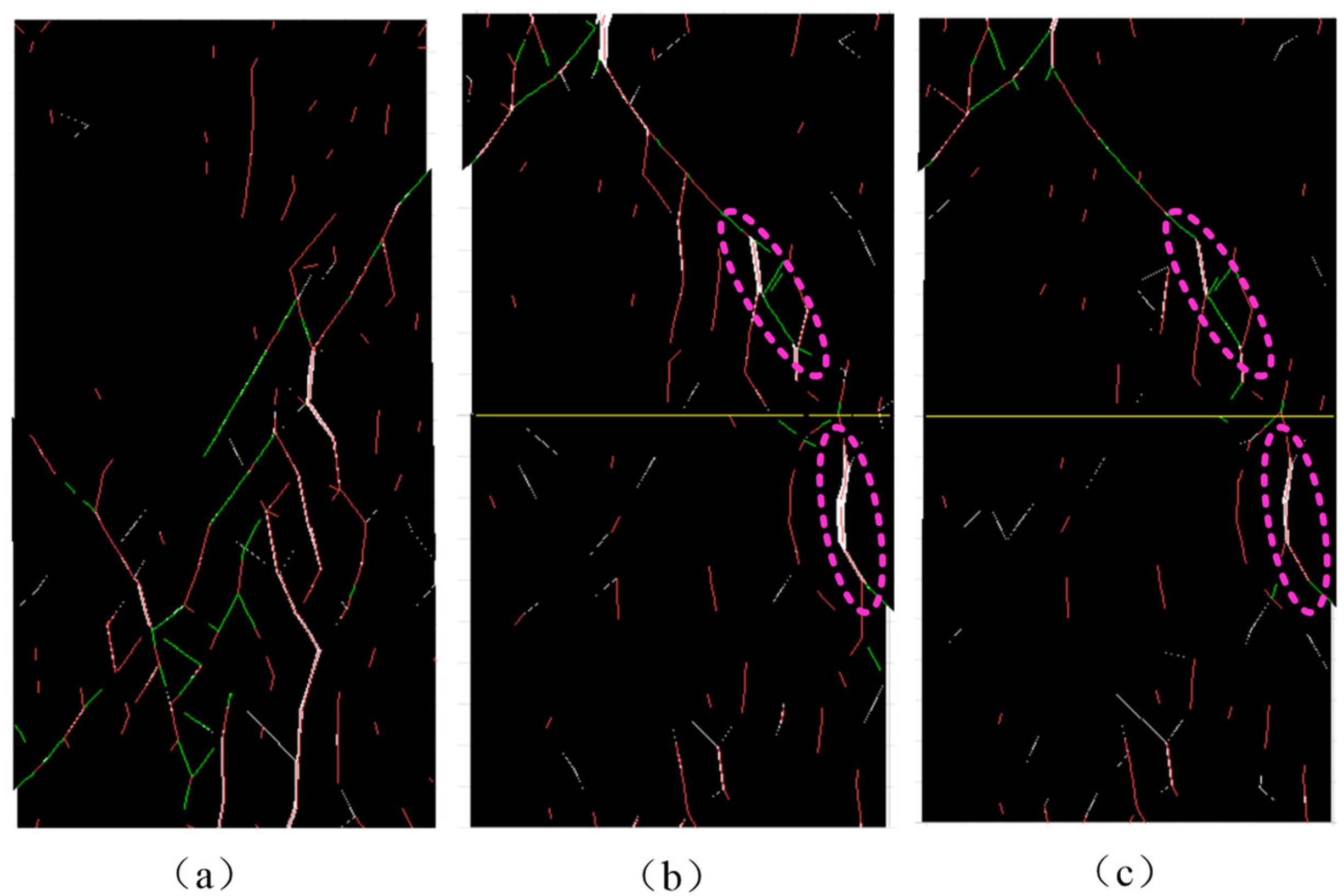
4.3.2. Damage Characteristic Analysis

According to fracture mechanics theory, when the stress intensity factor at the crack tip exceeds its fracture toughness, crack initiation occurs. In UDEC simulations, when the contact surface exceeds its ultimate strength, cracks are generated and continue to propagate. The criteria for determining cracking between the two have certain similarities. Therefore, analyzing the number of cracks and damage characteristics of anchored crack rock specimens under different pre-tension is illustrated in Figure 14. Red lines represent tensile cracks, while green lines represent shear cracks.
In Figure 14a, without support, the specimen’s failure primarily progresses along the pre-existing crack direction. Under external load, the pre-existing crack extends towards the upper right corner and the middle-lower position of the specimen, forming a tilted-through main crack within the specimen with multiple wing cracks around the main crack. Eventually, the specimen fails due to shear fracture.
Figure 14b,c shows the damage after low-pre-tensioned and high-pre-tensioned support, respectively. It is observed that the rockbolt support alters the crack propagation pattern and failure mode of the specimen. Since the rockbolt passes through the pre-existing crack in the specimen, no expansion occurs at this position; instead, the main crack forms from the upper 1/3 boundary to the right boundary of the specimen, exhibiting a splitting failure pattern. Comparing circled cracks, it is evident that under high pre-tension, the extent of crack opening is significantly reduced.
In general, without support, numerous tensile cracks are distributed inside the specimen. Upon installing a low-pre-tensioned rockbolt, tensile cracks mainly appear around the macroscopic crack and its vicinity. With further increase in pre-tension, tensile cracks only appear at the macroscopic crack, while other areas mainly exhibit shear cracks.
Figure 15 shows the evolution curves of crack numbers and damage degree for specimens anchored with different pre-tension. Table 5 provides the detailed statistics of the data presented in this Figure, with the change rates calculated in comparison to the unanchored group.
Analyzing the graph and Table data reveals that as damage degree significantly increases, the number of tensile and shear cracks also increases. Prior to peak strength, damage is mainly caused by shear cracks. In the post-peak stage, shear crack growth slows down and the number of tensile cracks begins to rise. Hence, although tensile cracks constitute a smaller proportion, they are the primary cause of macroscopic failure of the specimen. Prestressed rockbolts can effectively reduce the damage degree of crack specimens. Using rockbolts with different pre-tension results in a reduction of 5.7% and 17.4% in damage degree, 11.9% and 22.6% in shear crack numbers, and 18.8% and 42.9% in tensile crack numbers, respectively. The significant reduction in tensile crack numbers indicates the inhibitory effect of prestressed rockbolts on the initiation and propagation of tensile cracks. The inflection point of damage is observed at a strain value of 0.59% without anchoring, while for specimens anchored with low pre-tension, the inflection point occurs at a strain value of 0.57%. This slight advancement of the inflection point may be attributed to the initial ineffective active support of low-pre-tensioned rockbolts, requiring a certain amount of deformation damage before exerting active crack-arresting effects.
In conclusion, prestressed rockbolts enhance the mechanical performance of crack specimens, increase load-bearing capacity, and alter the failure mode of crack specimens. They reduce the number of internal cracks, suppress the initiation and propagation of tensile cracks, and decrease the damage degree of the specimens. Therefore, it is proposed to use high-pre-tensioned rockbolts to control the deformation of roadway surrounding rock in Ji-15-23090 headgate of Pingdingshan No. 4 Coal Mine.

5. Industrial Testing

5.1. Surrounding Rock Control Plan

The widening of the Ji-15-23090 headgate ranges from 600 mm to 800 mm. During the widening and repair period, experiments are conducted at the sides of the roadway to verify the effectiveness of tensioned rockbolts for surrounding rock control. In non-experimental sections, after widening, three additional Φ22 × 2400 mm left-handed high-strength resin rockbolts are installed in the sides, torqued to 300 N·m. In the experimental section, residual rockbolts after widening are directly tensioned to 60 kN for pre-tensioning. One day after installation, monitoring rockbolt axial forces showed that tensioned rockbolts generally exceeded 60 kN (Figure 16), whereas conventional rockbolts only reached 20–30 kN.

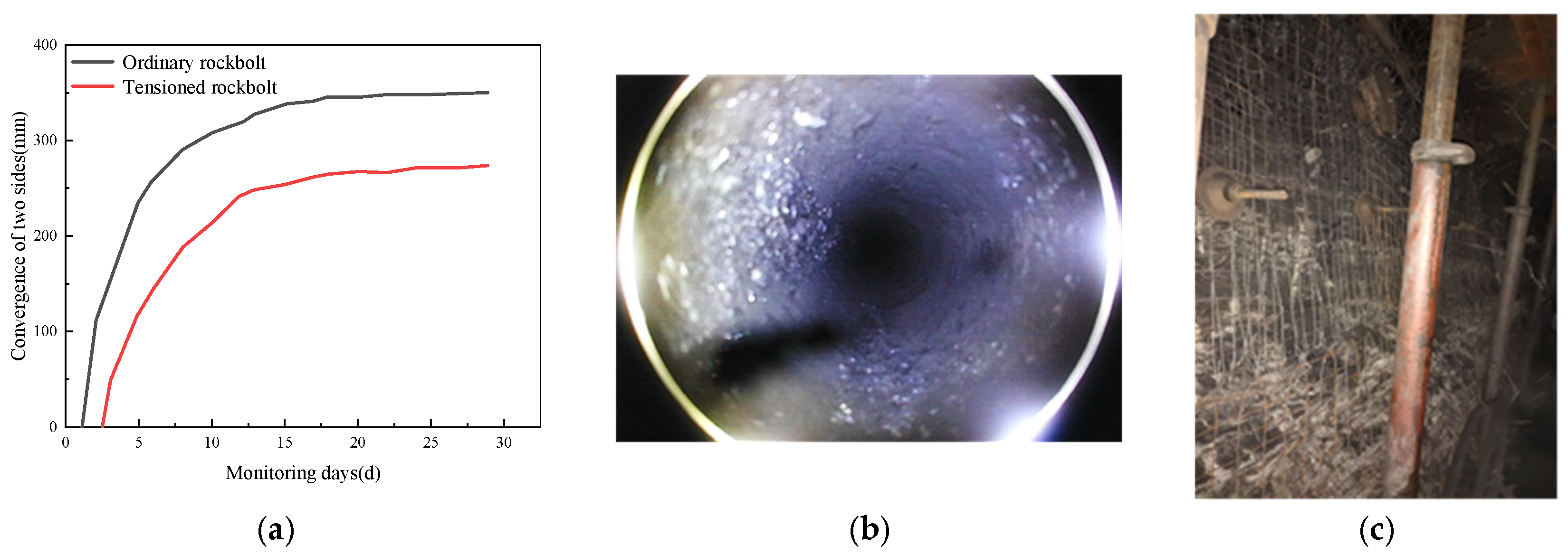
5.2. Analysis of Control Effectiveness

The cross-point method was used to observe the deformation of the two sides of the roadway in the experimental section and the non-experimental section, and the monitoring data were sorted into evolution curves. The borehole imager was used to peep at the side of the roadway in the test section, and the crack-arrest effect of the high-pre-tightening bolt was observed. The observation results are organized as shown in Figure 17.
In the non-experimental section, the deformation of two sides of the roadway is 350 mm. In contrast, in the section supported by tensioned rockbolts, the deformation is reduced to 273 mm, achieving a reduction of 22%. Borehole inspection results in the experimental section show good coal seam integrity with no longitudinal or circumferential crack distributions, and the borehole walls are smooth with good adherence of the rockbolts. The overall support effectiveness has significantly improved, with notable enhancement in the active load-bearing performance of the rockbolts. This confirms that the optimized support scheme provides excellent ground control.

6. Conclusions

(1)
Based on fracture mechanics theory, an influence model of rockbolt axial force is established to analyze the expression of the stress intensity factor difference in cracks within the anchoring range. The difference in stress intensity factor of cracks is related to parameters such as pre-tension, anchor point of the rockbolt, anchoring angle, and crack position. As the pre-tension increases and the anchor point moves towards the center of the crack, the stress intensity factor of the crack continuously decreases and moves away from the fracture toughness, thereby inhibiting the initiation and propagation of cracks.
(2)
Based on the modified parameters of the rockbolt and rock, a numerical analysis model is established. Simulation results show that high-pre-tensioned rockbolts significantly enhance the mechanical characteristics of the specimen: the peak strength of the specimen increases from 10.2 MPa to 12.5 MPa, a 22.5% improvement; the elastic modulus increases from 1.38 GPa to 1.82 GPa, a 31.9% improvement. Prestressed rockbolts not only suppress shear slip failure along pre-existing cracks, but also alter the expansion pattern of cracks and the failure mode of the specimen. After anchoring with high-pre-tensioned rockbolts, the damage degree of the crack specimen decreases by 17.4%, the number of shear cracks decreases by 22.6%, and the number of tensile cracks decreases by 42.9%.
(3)
By applying high-pre-tension to rockbolts after widening the roadway, the axial forces of rockbolts have been increased from 20 to 30 kN to over 60 kN. A comparison of mining pressure observation data between the experimental and non-experimental sections reveals that the deformation of the two sides of the roadway is reduced by 22%, from 350 mm in the non-experimental section to 273 mm in the experimental section. Borehole inspection results in the experimental section show good integrity of the coal seam in the sidewall. Increasing the pre-tension of rockbolts has achieved effective control of the surrounding rock.

Author Contributions

Conceptualization, B.W.; methodology, B.W. and X.W.; software, B.W. and D.C.; data curation, J.C., W.S. and C.L.; writing—original draft preparation, B.W. and D.C.; writing—review and editing, X.W. and J.C.; funding acquisition, B.W. and J.C. All authors have read and agreed to the published version of the manuscript.

Funding

This research was funded by National Natural Science Foundation of China, grant number 52204079, National Natural Science Foundation of China, grant number 52104117, Scientific Research Foundation for High-level Talents of Anhui University of Science and Technology, grant number 2024yjrc48 and Anhui Province Excellent Research and Innovation Team, grant number 2023AH010023.

Data Availability Statement

The data used to support the findings of this study are included within the article.

Conflicts of Interest

The authors declare no conflicts of interest.

References

  1. Kang, H. Development and prospects of support and reinforcement materials for coal mine roadways. Coal Sci. Technol. 2021, 49, 1–11. [Google Scholar]
  2. Chen, D.; Wang, X.; Zhang, F.; Bai, J.; Zhao, X.; Li, M.; Yu, Y.; Wang, X. Study on the mechanism of progressive instability of special-shaped coal pillar and the stability control of roadway under the influence of mining. Rock Mech. Rock Eng. 2024, 57, 6461–6483. [Google Scholar] [CrossRef]
  3. Kang, H.; Yuan, G.; Si, L.; Gao, F.; Lou, J.; Yang, J.; Dong, S. Mechanical behavior and failure mechanisms of rock bolts subjected to static-dynamic loads. Int. J. Min. Sci. Technol. 2024, 34, 281–288. [Google Scholar] [CrossRef]
  4. Kang, H. Seventy years development and prospects of strata control technologies for coal mine roadways in China. Chin. J. Rock Mech. Eng. 2021, 40, 1–30. [Google Scholar]
  5. Chen, W.; Wang, L.; Tan, X.; Yang, D.; Yuan, J.; Yang, J. State-of-the-art and development tendency of the underground engineering stability of fractured rock mass. Chin. J. Rock Mech. Eng. 2021, 40, 1945–1961. [Google Scholar]
  6. Wang, W.J.; Dong, E.Y.; Zhao, Z.W.; Wu, H.; Yuan, C. Experimental study on mechanical properties of anchorage body and on anchorage mechanism. J. China Coal Soc. 2020, 45, 82–89. [Google Scholar]
  7. Wei, S.; Li, X.; Huang, Y. Present situation and prospect of damage mechanism and surrounding rock control of anchored fractured rock. Coal Eng. 2023, 55, 88–95. [Google Scholar]
  8. Vandermaat, D.; Saydam, S.; Hagan, P.C.; Crosky, A.G. Examination of rockbolt stress corrosion cracking utilising full size rockbolts in a controlled mine environment. Int. J. Rock Mech. Min. Sci. 2016, 81, 86–95. [Google Scholar] [CrossRef]
  9. Liu, A.Q.; Ju, W.J.; Hu, H.T.; Wang, X. Experiment study on the effect of bolt prestress on the shear behavior of jointed rock mass. J. China Coal Soc. 2013, 38, 391–396. [Google Scholar]
  10. Liu, Q.S.; Lei, G.F.; Peng, X.X.; Wei, L.; Luo, C.Y. Study on shear mechanical properties of sandstone, marble and granite after anchoring. Chin. J. Rock Mech. Eng. 2018, 37, 4007–4015. [Google Scholar]
  11. Liu, Q.; Lei, G.; Peng, X.; Wei, L.; Liu, J.; Pan, Y. Experimental study and mechanism analysis of influence of bolt anchoring on shear properties of jointed rock mass. Rock Soil Mech. 2017, 38, 27–35. [Google Scholar]
  12. Zhou, S.; Ji, X.; Li, L.; Liu, H.; Zhu, C.; Fan, H.; Zhang, Q.; Shi, C. The mechanism of rockbolts in jointed rock under uniaxial tension. KSCE J. Civ. Eng. 2023, 27, 4938–4947. [Google Scholar] [CrossRef]
  13. Wang, G.; Wang, X.; Yang, J.; Zhu, X. Mechanism analysis of pre-stressed bonded rockbolt controlling the deformation in joint surround rocks. J. China Univ. Min. Technol. 2021, 50, 60–68. [Google Scholar]
  14. Shi, H.; Zhang, H.; Chen, W.; Song, L.; Li, M. Pull-out debonding characteristics of rockbolt with prefabricated cracks in rock: A numerical study based on particle flow code. Comput. Part. Mech. 2024, 11, 29–53. [Google Scholar] [CrossRef]
  15. Teng, J.; Tang, J.; Zhang, Y.; Li, X. CT experimental study on the damage characteristics of anchored layered rocks. KSCE J. Civ. Eng. 2018, 22, 3653–3662. [Google Scholar] [CrossRef]
  16. Zhao, T.; Zou, J.; Fu, Z.; Yu, F. Experimental study on anchoring mechanism of double persistent jointed rock. J. China Coal Soc. 2020, 45, 3065–3072. [Google Scholar]
  17. Wang, T.; Wang, W.; Du, Y. Research on pre-tensioned bolts reinforcing roadway roof in joint rock mass. J. China Univ. Min. Technol. 2007, 36, 618–621. [Google Scholar]
  18. Wu, Q.; Chen, L.; Shen, B.; Dlamini, B.; Li, S.; Zhu, Y. Experimental investigation on rockbolt performance under the tension load. Rock Mech. Rock Eng. 2019, 52, 4605–4618. [Google Scholar] [CrossRef]
  19. Zu, G.; Wang, J.; Ning, J.; Pu, Z.; Yan, L.; Ren, Z.; Hu, H. Experimental study on anchoring crack-resistance effects of prestressed anchor under impact loads. Chin. J. Geol. Eng. 2023, 45, 1743–1753. [Google Scholar]
  20. Zhang, J.P.; Liu, L.M.; Liu, C.X.; Sun, D.L.; Shao, J.; Li, Y. Research on mechanism of bolt-grouting reinforcement for deep fractured rock mass based on prestressed anchor and self-stress grouting. Rock Soil Mech. 2020, 41, 3651–3662. [Google Scholar]
  21. Li, S.; Chen, W.; Zhu, W.; Wang, S. Catastrophe model of crack propagating in bolt-supported jointed rockmass. Chin. J. Rock Mech. Eng. 2003, 22, 1661–1666. [Google Scholar]
  22. Ge, R.; Liu, J. Study on shear performance of anchored joint surface. Chin. J. GeoEng. 1988, 1, 8–19. [Google Scholar]
  23. Wang, P.; Feng, T.; Zhu, Y.; Yu, W. Experimental study and numerical simulation of anchoring mechanism of anchored rocklike material with prefabricated fracture. Rock Soil Mech. 2016, 37, 793–801. [Google Scholar]
  24. Yuan, K.; Jiang, Y.; Chu, Z.; Wang, G.; Gong, B. Microscopic research on anchorage mechanism of bolted rock joint based on DEM. J. Shangdong Univ. Sci. Technol. Nat. Sci. 2014, 33, 76–84. [Google Scholar]
  25. Zhou, H.; Xu, R.; Zhang, C.; Shen, Z.; Meng, F.; Liu, H. Experimental study of crack prevention effect of pre-stressed bolt anchoring. Chin. J. Rock Mech. Eng. 2015, 34, 2027–2037. [Google Scholar]
  26. Chen, Y.; Yang, Y.; Yan, S.; Hao, S.; Cao, Q. Study on reinforcement mechanism of filling body in gob-side entry retaining. J. Min. Saf. Eng. 2018, 35, 1129–1134. [Google Scholar]
  27. Wu, B.; Wang, X.; Bai, J.; Wu, W.; Zhu, X.; Li, G. Study on crack evolution mechanism of roadside backfill body in gob-side entry retaining based on UDEC trigon model. Rock Mech. Rock Eng. 2019, 52, 3385–3399. [Google Scholar] [CrossRef]
  28. Wu, Y. Study on Tunnel Stability and Reinforcing Mechanism of Bolts and Shotcrete Based on Rock Fracture Mechanics. Ph.D. Thesis, Huazhong University of Science and Technology, Wuhan, China, 2004. [Google Scholar]
  29. Sheng, K. Fracture Mechanics; Tongji University Press: Shanghai, China, 1996; pp. 1–3. [Google Scholar]
  30. You, C. Theory and Application Study on Stress-Transfer Mechanism of Anchoring System. Ph.D. Thesis, Shandong University of Science and Technology, Qingdao, China, 2004. [Google Scholar]
  31. Zheng, Y. Explaining Bolt—Shotcrete support mechanism by fracture mechanics. Coal Sci. Technol. 1980, 7, 11–14+64. [Google Scholar]
  32. Yi, S.; Zhu, Z. Introduction to Fracture Rock Mass Damage Mechanics; Science Press: Beijing, China, 2005; pp. 25–26. [Google Scholar]
  33. Wu, D.; Yu, L.; Su, H.; Wu, J.; Liu, R.; Zhou, J. Experimental study and PFC3D simulation on crack propagation of fractured rock-like specimens with bolts under uniaxial compression. Rock Soil Mech. 2021, 42, 1681–1692. [Google Scholar]
  34. Hu, X.; He, C.; Walton, G.; Chen, Z. A combined support system associated with the segmental lining in a jointed rock mass: The case of the inclined shaft tunnel at the bulianta coal mine. Rock Mech. Rock Eng. 2020, 53, 2653–2669. [Google Scholar] [CrossRef]
  35. Zhou, L.; Jiang, Y.; Zhu, Z.; Dong, Y.; Niu, C.; Wang, M. Mechanism study of preventing crack propagation of fractured rock under dynamic loads. Explor. Shock Waves 2021, 41, 34–44. [Google Scholar]
  36. Liu, S.; Xiao, F.; Li, T.; Zhang, B. Analysis of impact tendency and sensitivity of fractured rock with different crack arrest measures. Sustainability 2022, 14, 13833. [Google Scholar] [CrossRef]
Figure 1. Original support scheme and deformation of roadway. (a) Original roadway support scheme. (b) Roadway deformation situation.
Buildings 14 02584 g001
Figure 2. Peeping results of roadway side.
Buildings 14 02584 g002
Figure 3. Theoretical analysis model. (a) Theoretical model of the stress intensity factor at the crack tip in anchored surrounding rock; (b) in situ stress influence model; (c) rockbolt axial force influence model.
Buildings 14 02584 g003
Figure 4. Concentrated shear force model of cracks in an infinite plate.
Buildings 14 02584 g004
Figure 5. Diagram of value b change and its relation with semi-minor axis of ellipse (c) (The yellow line represents the rockbolts).
Buildings 14 02584 g005
Figure 6. Calculation model of relationship between crack opening and normal stress.
Buildings 14 02584 g006
Figure 7. Relationship between b value and normal stress.
Buildings 14 02584 g007
Figure 8. The evolution curve of strength factor difference under different pre-tension.
Buildings 14 02584 g008
Figure 9. Numerical calculation model (a) without anchoring; (b) pre-tension 40 kN; (c) pre-tension 90 kN.
Buildings 14 02584 g009
Figure 10. Correction results of rock parameters.
Buildings 14 02584 g010
Figure 11. Numerical model diagram of rockbolt drawing.
Buildings 14 02584 g011
Figure 12. Correction results of rockbolt element parameters.
Buildings 14 02584 g012
Figure 13. Stress–strain curves of specimens under different pre-tension.
Buildings 14 02584 g013
Figure 14. Damage characteristics of specimens under different pre-tension (a) without anchoring; (b) low pre-tension; (c) high pre-tension.
Buildings 14 02584 g014
Figure 15. The evolution curves of crack number and damage degree of cracked specimens with different pre-tension (a) without anchoring; (b) low pre-tension; (c) high pre-tension.
Buildings 14 02584 g015
Figure 16. Axial force of tensioned rockbolt.
Buildings 14 02584 g016
Figure 17. Field observation results. (a) Convergence of two sides. (b) Borehole inspection of the sidewalls in the experimental section. (c) Support effectiveness.
Buildings 14 02584 g017
Table 1. General parameter assignment of intensity factor difference analysis.
General ParametersValue
Elastic modulus of rockbolt/GPa200
Elastic modulus of rock/GPa1.8
Poisson’s ratio of rock0.25
Radius of rockbolt/mm11
Length of rockbolt/m2.8
Angle between rockbolt and crack/°60
Normal stiffness of crack/(GPa·m−1)200
Shear strength of crack/MPa2
Friction angle of crack/(°)30
Cohesion of crack/MPa1
Short semi-axis of crack/m0.1
Distance from hole mouth/m0.1
Long semi-axis of crack/m0.2
Table 2. Simulation scheme.
GroupPre-Tension (Load)/MPaLoading Speed/(m·s−1)
10 (without rockbolt)0.02
20.105
30.237
Table 3. Simulation parameters of rock.
CategoryDensity/
(kg·m−3)
Bulk Modulus/
GPa
Shear
Modulus/GPa
Cohesion/
MPa
Friction Angle/(°)Tensile Strength/MPa
Block18001.20.726.3 (εp = 0)261.2
4.9 (εp = 0.002)
0.2 (εp = 0.005)
Contact surfaceNormal stiffness/
(GPa·m−1)
Tangential stiffness/
(GPa·m−1)
Cohesion
/MPa
Friction
angle/(°)
Tensile strength/MPa
21686.43.8171.2
Table 4. Rockbolts and anchoring parameters.
Cross-sectional area/(m2)Elastic
modulus/GPa
Yield limit/
kN
Moment of inertia of the cross-section/(m4)Failure strain limit
Rockbolt3.8 × 10−42001281.2 × 10−80.15
Exposed
perimeter/m
Cohesive strength of
tangential
coupling spring/MPa
Stiffness of
tangential
coupling spring/
(GPa·m−1)
Friction
angle of
tangential coupling spring/(°)
Cohesive strength of normal
coupling spring/MPa
Stiffness of normal
coupling spring/
(GPa·m−1)
Friction angle of normal coupling spring/(°)
Anchoring parameters0.071845200200
Table 5. Comparison of damage data of specimens.
Without
Anchoring
Low
Pre-Tension
High
Pre-Tension
Change Rate/%
Damage degree/%52.149.143−5.7
−17.4
Number of shear cracks/count1063936823−11.9
−22.6
Number of tensile cracks/count1129164−18.8
−42.9
Disclaimer/Publisher’s Note: The statements, opinions and data contained in all publications are solely those of the individual author(s) and contributor(s) and not of MDPI and/or the editor(s). MDPI and/or the editor(s) disclaim responsibility for any injury to people or property resulting from any ideas, methods, instructions or products referred to in the content.

