Article

Nonplanar Robotic Printing of Earth-Based Material: A Case Study Using Cob-like Mixture

1
College of Arts and Creative Enterprises, Zayed University, Abu Dhabi P.O. Box 144534, United Arab Emirates
2
Welsh School of Architecture, Cardiff University, Cardiff CF10 3NB, UK
*
Author to whom correspondence should be addressed.
Buildings 2024, 14(8), 2589; https://doi.org/10.3390/buildings14082589
Submission received: 8 July 2024 / Revised: 7 August 2024 / Accepted: 15 August 2024 / Published: 22 August 2024
(This article belongs to the Special Issue Research on Construction Innovation and Digitization)

Abstract

:
The study presents an integration of cob with robotic processes. By challenging conventional monolithic earth-building methods, the study proposes the use of spatial nonplanar formations that are robotically fabricated, presenting an alternative geometric language for earth construction. The research methodology is derived from existing factors within the robotic lab, encompassing both constant and variable parameters. Through an experimental approach, the variables are systematically manipulated while observing the outcomes to identify patterns and relationships. Incremental refinements to the research conditions result in an optimal equilibrium state within the defined lab parameters. An empirical investigation approach serves as the foundation for controlling the printing process; wherein an iterative adjustment of the robot extrusion parameters is based on the behaviour of the deposited material. The outcome is several robotically printed cob nonplanar prototypes. Depending on their geometric formations and complexity, the printing process combined three variations: continuous, intervals, and modular. The latter enabled the production of a cob arch, serving as proof of feasibility for the creation of modular cob structures through a segmented assembly process. The study contributes to expanding the possibilities of cob construction by leveraging robotic technologies and paving the way for innovative applications of cob in contemporary architecture practices.

1. Introduction

Cob, an ancient earth-building technique, has been utilised across various regions of the world for thousands of years [1,2,3,4]. However, compared to other earth construction methods, cob is the least documented [5]. In recent years, there has been a renewed interest in cob construction as a form of vernacular earth architecture [6,7,8], primarily due to its low environmental impact and adaptability to different climatic conditions. The versatility and application techniques of cob have contributed to its widespread use in various geographical locations, including England and Wales [9,10,11], several European countries such as Italy [12], France [13], Belgium [14], and Germany [15], various regions in Africa [16], India [17] and some areas in Yemen [18] and Saudi Arabia [19].
Traditionally, cob construction involves sourcing, preparing, mixing, applying, and rectifying the raw materials as they dry [2]. The subsoil was typically obtained locally or in proximity to the construction site [20], as evident from the correlation between the examined cob next to heritage building sites [20,21]. The mixed, wet cob was manually compacted without the need for shuttering or formwork. It was applied in successive layers, allowing each layer to dry before applying the next, resulting in the formation of solid walls measuring 600–1000 mm. During the drying process, the layers were trimmed to attain the desired final shape [2]. Despite the seemingly simple cob recipe consisting of subsoil, fibres (typically straw), and water, the intricacies of the cob-making process have gradually been lost over time. This decline can be attributed to the rise of modern materials, the depreciation of cob construction practices in today’s building industry worldwide, and the exclusion of cob from modern building codes, permits, and regulations [22,23,24]. Working and building with cob relies heavily on the accumulated experience of the builders [25] and employs nonphysical qualities that rely on senses such as touch, sight, smell, taste, and hearing [2]. Unfortunately, this knowledge has been primarily transmitted orally and remains largely undocumented.
In recent years, there has been a growing interest in 3D printing and robotic fabrication processes for cob extrusion systems [26,27,28,29] utilising the latest trends in architectural robotic fabrication. This interest has also been driven by the search for more sustainable practices and alternative solutions to mitigate the environmental impact of current building industry practices, including the widespread use of concrete [30].
A recent comparative study by Alhumayani et al. investigated the environmental impacts of conventional and large-scale 3D printing construction processes using concrete and cob materials, employing a life cycle assessment methodology focused on load-bearing walls in small to medium-sized houses. The study found that conventional cob construction exhibited the lowest overall environmental impact and global warming potential, followed by 3D-printed cob. In contrast, conventional concrete construction showed the highest environmental impact, with significant contributions from reinforcing steel and cement. The study highlighted that 3D-printed concrete offers more than a 50% reduction in environmental impact compared to conventional concrete, largely due to the absence of reinforcing steel. However, 3D-printed cob outperformed 3D-printed concrete in reducing global warming potential, stratospheric ozone depletion, and particulate matter formation. A significant factor in the environmental impact of 3D-printed cob was the electricity consumption required for robotic operations, which accounted for 83% of its total impact. This research underscores the potential of 3D printing technologies in sustainable construction, particularly when renewable energy sources are used to mitigate the environmental impacts associated with electricity consumption for robotic operations [31].
This paper eliminates all other forms of earth architecture and focuses exclusively on the cob, merging it with methodologies of nonplanar printing and robotic extrusion systems. It proposes a language that emerges from the combination of earth materials and digital robotic fabrication technology. Currently, there are limited examples of nonplanar geometries that are associated with robotic spatial additive manufacturing and material extrusion processes [32,33,34,35,36,37], none of which involve earth-building materials. The presented case study adopts the concept of human-robot collaboration [38,39,40,41,42,43] as a method to address and gain control over the variability in the system. It challenges planar printing and the notion of digital contour crafting [44,45] by introducing nonparallel spatial toolpath trajectories that direct robot movement and are thus associated with material disposition and accumulation.
This research builds upon the previous work conducted by Gomaa [27,46] and Gin [47] in the same robotic lab at the Welsh School of Architecture, Cardiff University. It explores the constants and variable parameters associated with materiality, technology, digital and physical settings, spatial configurations, geometrical inquiries, and design intents. The presented case study serves as a preliminary investigation into the feasibility of nonplanar robotic printing of cob-like mixtures. The paper begins with an overview of current examples focusing specifically on cob construction and materiality. It then discusses the specificities of the research conducted within the lab settings, followed by an exploration of the cob material behaviour in the three extrusion phases. The resulting prototypes are presented and analysed, reflecting on the three categories of the printing process. The research negates the notion of a continuous printing process and instead adopts a modular construction and assembly approach. It showcases several nonplanar modules and presents a successful assembly of an arch. Finally, the paper concludes with recommendations to improve the system and outlines provisions for future phases of work.

2. Examination of Current Cob Case Studies

The concept of contour crafting originated from a study conducted by Khoshnevis in 2004 [48]. It refers to the computer-controlled layered deposition of building material on a design-predetermined path. Since then, contour crafting has become the foundation technology of all 3D construction printing techniques [49], including cob and other earth-based materials. Contour crafting has been recognised as a suitable method for large-scale fabrication [50,51] and has been integrated with digital fabrication in the architecture and building industry [52]. While concrete 3D printing has gained wide popularity in the past five years [53,54,55,56], construction with earth-based materials remains highly experimental and is still in its early stages. The following is a brief overview that combines both applied projects and material design research carried out in recent years.
The Institute for Advanced Architecture of Catalonia (IAAC) has conducted several designs and built experiments in recent years. These include a robotically 3D-printed two-meter clay column in 2015 [57], a modular block wall from 3D-printed clay in 2017 [58], and a 5-m-high digital adobe wall from interlocking module blocks in 2018 [59].
Likewise, the World’s Advanced Saving Project (WASP) has been working on developing systems suitable for full-scale earth construction. In 2016, they developed the WASP crane system for large-scale earth 3D printing, which led to the realization of the Eremo 3D printed house in 2017 [29]. In 2018, they printed the walls for the first complete house (Gaia) in Italy using onsite mixtures of subsoil, water, rice straw, rice husk, and lime [60]. Other examples include the TECLA house in Italy in 2021 [61], a concept DIOR store in the UAE in 2021 [62], a house of dust in Germany in 2021 [63], and the ongoing ITACA project in Italy [64]. In 2019, IAAC and WASP collaborated on a wall prototype for embedded interlocking timber stairs. The aim was to test the load-bearing capabilities of 3D-printed cob [65]. In 2021, they also worked on a modular system installation that combined 3D-printed earth with timber elements to support bridging an arch [66]. In the United States, 3D Potter and Emerging Objects built several 3D printed prototypes, including a wall as part of the Mud Frontiers project in 2019 [67] and living space huts in 2020 [68].
Several early studies have investigated cob 3D printing technology. Perrot examined the hardening properties of cob and explored different material mixes, relating them to the constraints created during the process [69]. Amnah researched different cob mixtures and their implications for printability and buildability and conducted several lab tests to evaluate selected properties between cast and 3D-printed cob [26].
Within Cardiff University Robotic Lab, robotic 3D printing of cob has been extensively researched and investigated. The work began in 2018 with a feasibility study conducted by a team from Cardiff University (UK), the University of Plymouth (UK), and the University of Adelaide (Australia). This exploration led to the development of a unique bespoke dual extrusion system and included research on material mix properties, as well as investigations into robotic 3D printed geometry through three printed tests. The first test assessed the printed layer ‘lift’ height, the second examined horizontal corbelling using 3-axis 3D printing, and the last one looked at radial corbelling using 6-axis 3D printing [46]. In April 2022, another collaboration with Cambridge University resulted in a vertical assembly of eight building blocks [47].
Reflecting on the above, only one of the tests conducted at Cardiff robotic lab utilised the robot 6-axis capability following a radial trajectory, while the remaining test prints in the lab used the robot 3-axis and deposited the material on a horizontal surface in the XY cartesian plane. Likewise, in the studies conducted by Perrot and Amnah, while they tested the variation in material compression when inclining the tool head, they also deposited the material on a horizontal surface in the XY cartesian plane. All remaining case studies used standard gantry 3D printing style.
The presented research challenges the approaches mentioned above by generating three-dimensional spatial geometries using nonparallel toolpaths that change direction in their trajectory, thus proposing novice geometrical formations that were not achievable before. The movement of the robot and, consequently, the disposition of the material exhibit a perpendicular relation to the toolpath. The research aims to find an equilibrium state between the various physical and digital parameters and the existing systems in the lab. It takes into consideration constraints such as the reach of the robot and the pumping force of the extruder and utilises them as design parameters. The working process within the lab defines the constants and, over time, through a trial-and-error methodology, gains control over the variables, including cob mix rheology and geometry design. By contesting automation, the system and the designer become an extension of a unified entity that works synergistically, reacting and learning over time.

3. Methods, Materials, and Working Process

3.1. Lab Setting and Used Equipment

The working area extended beyond Cardiff Robotic Lab to include an outdoor dedicated storage slot for the subsoil and a shared casting room used to prepare the wet cob mixes. The robotic lab, in addition to housing the robot and the robot controller, also included the dual-extruder system, an area for storing the wet cob, and an area for sub-soil crushing and sieving (refer to Figure 1). The set system within the lab is based on a bespoke extrusion model with a unique dual-cartridge design that employs a sequential extrusion process. This system was specifically designed and engineered in 2018 to extrude and work with wet-like cob [46]. In 2020, the cob extruder was integrated with the industrial robot Kuka KR 60 HA using variable-frequency drive (VFD) control motors, allowing simultaneous operation through the Kuka pendant using the same code file. While the dual extruder system was dry-tested and proven to work as a continuous printing process [46], the dual system was never verified with an actual physical printed output. Given the experimental nature of the methodology, the procedural workflow necessitated ongoing refinement of both the extruder design and comprehensive system settings. This iterative process ran concurrently as an integral aspect, actively informing the design nuances and resulting in nonplanar printed geometry. The implemented modifications are summarised in four main points:
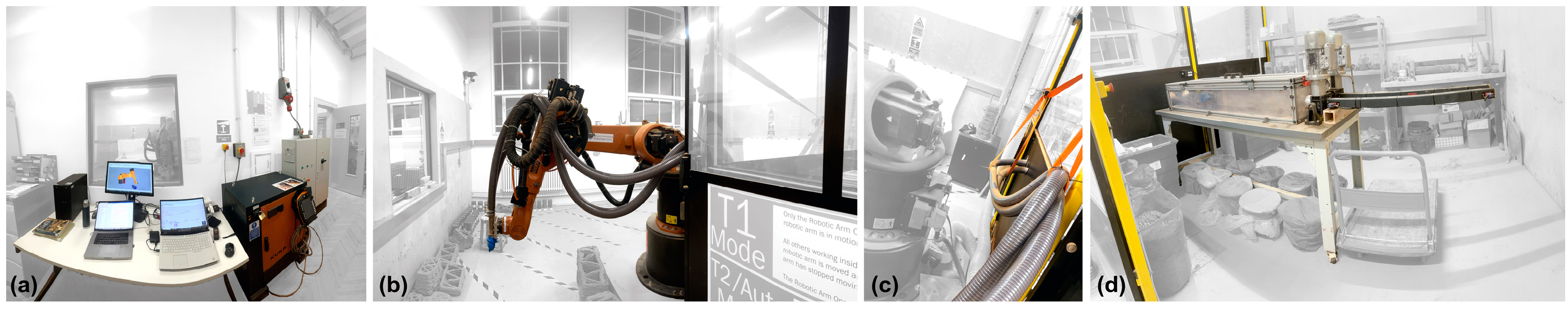
  • The location of the printing surface was moved 180° around the centre of the robot location to comply with the updated health and safety regulations within the university. This change in printing location affected the hose length, increasing it from 2 to 3 m to allow for a certain freedom in robot movement. The increased hose length resulted in a greater amount of material being pushed by the extruder, thus, in turn, affecting the required force in relation to material resistance. Due to the variable frequency of the extruder’s control motors, the speed and, therefore, the force of the pushing plate varied in relation to the material’s resistance. Increasing the length of the hose resulted in an increased volume of the pushed material, which led to a substantial increase in material resistance that the dual extruder was unable to cope with, resulting in a complete stop. Therefore, it was important to identify the optimal hose length in relation to the extruder’s pushing force, the rheology of the wet cob, and the build-up of the outputted prototype;
  • Two 3 m hoses were directly connected to the two tubes held by the extruder through two funnels, replacing the originally designed two-way aluminium channel. The two hoses converged through a two-way channel attached to the end of the robot arm. This configuration ensured that the material was consistently pushed forward, eliminating any issues with retraction. The pressure and weight of the material in the hoses and tubes, combined with the force of gravity, prevented the material from moving in the reverse direction;
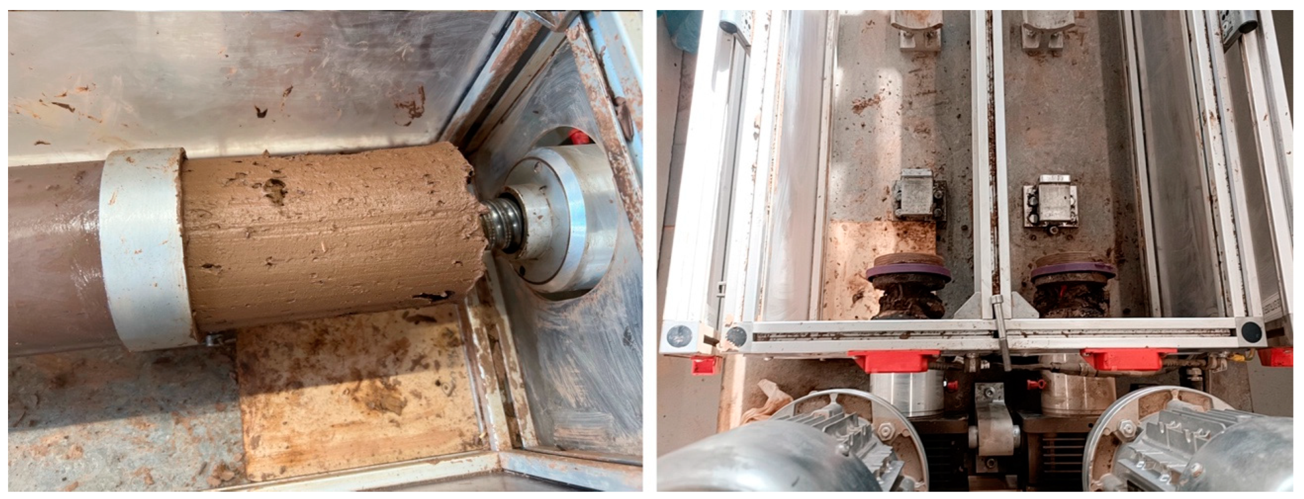
  • A rubber seal was added to the push plates of extruder 1 and extruder 2 to prevent the cob material from retracting and ensure its continuous forward movement. The design of the rubber seal underwent several iterations during the experiment to optimise its effectiveness. (Refer to Figure 2);
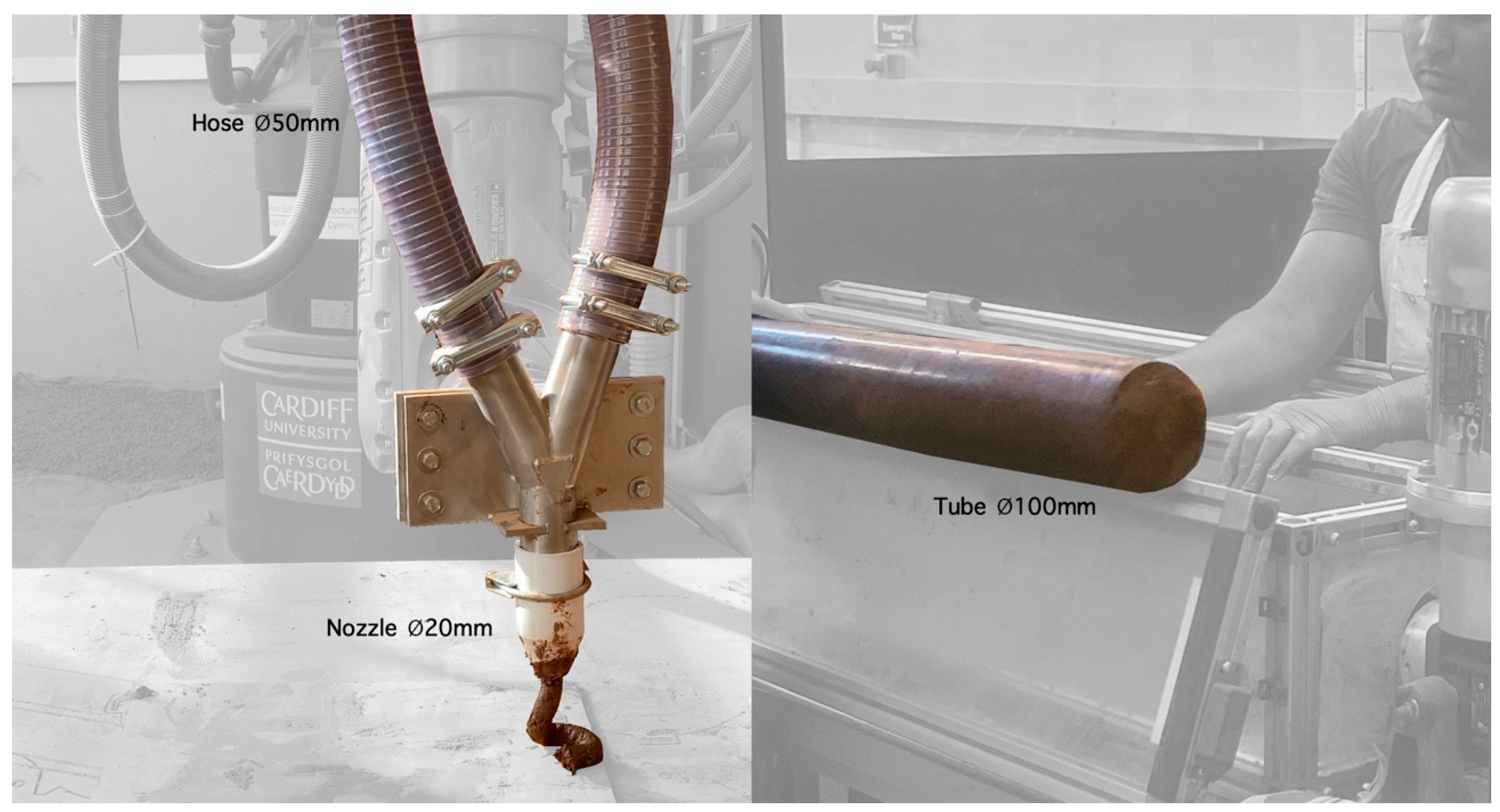
  • A 3D-printed 20 mm nozzle was attached to the two-way channel at the end of the robot arm and used for all the printed prototypes. The smaller nozzle size allowed for more precise control over the printed geometry and helped reduce air gaps as the material was compacted at points where the diameter decreased, transitioning from 100 mm tubes to 50 mm hoses to 20 mm nozzles. (Refer to Figure 3);
As a result of the modifications, previous recipes used in the lab could not be adopted as they no longer worked with the changed parameters. The system consists of four main parts integrated into one lab setting (refer to Figure 4): a. The computer and both controller cabinets for the robot and the extruder, b. The Kuka robot is positioned on a 130 mm height plinth, c. The two hoses that connect the extruder to the robot, and d. The extruder is connected to the controller cabinet floor trunking.

3.2. Working Methodology

Understanding the different modes of interactions within the existing system and gaining control over the parameters was a gradual process of learning and investigation. This study involved active experimentation using a trial-and-error methodology to explore and determine the limitations of the extruder, robot, geometry, and material within the working laboratory setting. This problem-solving approach enabled the exploration of various attempts and iterations to find solutions, answers, or directions. It involved systematically trying out different possibilities, observing the outcomes, and learning from the results to refine the approach.
Throughout the process, different options were explored, adjustments were made, and the process was iterated until a desired outcome was achieved or a deeper understanding of the problem being investigated was obtained. This methodology proved to be particularly useful due to the complexity of the researched subject and the presence of uncertain problems with no clear path to a solution. It facilitated the exploration of different avenues, the identification of what worked and what did not, and the incremental implementation based on observed results. The process involved continuous testing, analysis, and adjustment of variables or parameters until a satisfactory outcome was achieved.
A systematic approach was followed to understand and monitor the variables and constants, with tweaks and modifications gradually incorporated into the system or process. Control was exercised by keeping track of the changes made, documenting the results, and using observations to inform subsequent iterations. This was done through photographing and video recording from different angles, as well as recording changes and observations in a document.
The outcomes were assessed and fed back into the process to determine and outline the next steps. The iterative research process allowed for progress and refinement of methods and approaches to find solutions to encountered problems and advance the research by gaining control and understanding of the system. Towards the end of the research period, an equilibrium stage was reached. The equilibrium phase was defined as gaining an understanding and control over the work, enabling the geometry design and its successful printing.
To facilitate the research, spatial articulation within the lab was carefully allocated in relation to the working process. This was dictated by the nature of the material and the requirements of the tasks performed (refer to Figure 5). The working process can be summarised into seven steps:
  • Preparing the cob’s dry ingredients;
  • Preparing the wet cob mixture and storing it;
  • Testing the viscosity of the mixture and adjusting it to achieve the desired fluidity;
  • Filling the tubes with the cob mixture;
  • Loading the tubes into the extruder;
  • Preparing the digital file for the desired geometry and dry testing for clashes that were not digitally simulated;
  • Printing the desired geometry.

3.3. Cob Material and Robotic Extrusion System

The material in the lab was classified into three main states for printable cob mixture design: pre-extrusion, during-extrusion, and post-extrusion. The behaviour across these three states was interrelated and influenced the process of material preparation. A recipe was developed through a process of trial and error, observation, and troubleshooting spanning the three states. The knowledge of “know-how” was derived, verified, and then systematised to ensure consistent and repetitive application in subsequent working stages. This approach aligned with historical practices, where the mixture preparation and working with cob were skills mastered by local communities and passed down orally through generations [69,70]. Throughout the research, the cob mixture was assessed using standard field tests [2,71]. These included the shake test, the brick test, the sausage test, and the ball drop test. These tests were slightly modified to suit the digital extrusion process. Observations, recordings, and analysis were conducted in a systematic feedback loop across the three phases to inform further adjustments and improvements:
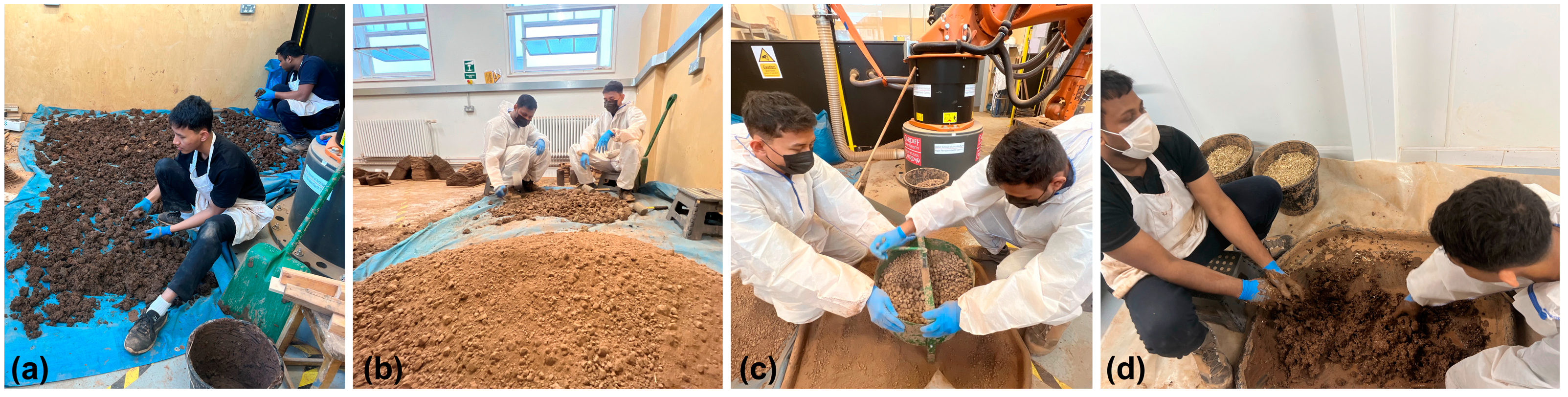
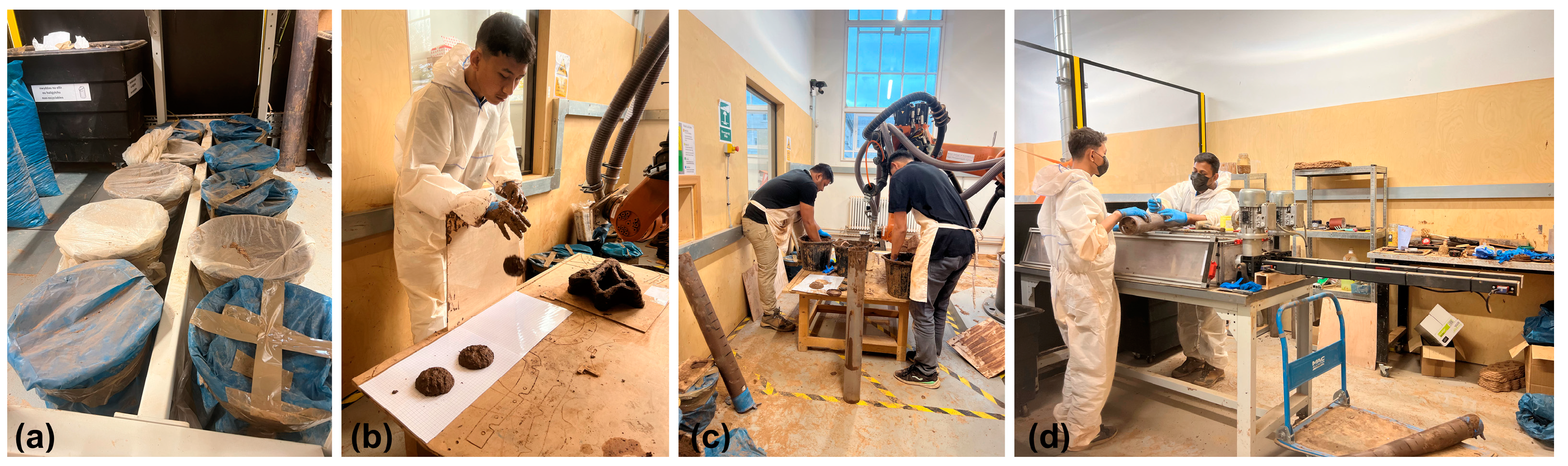
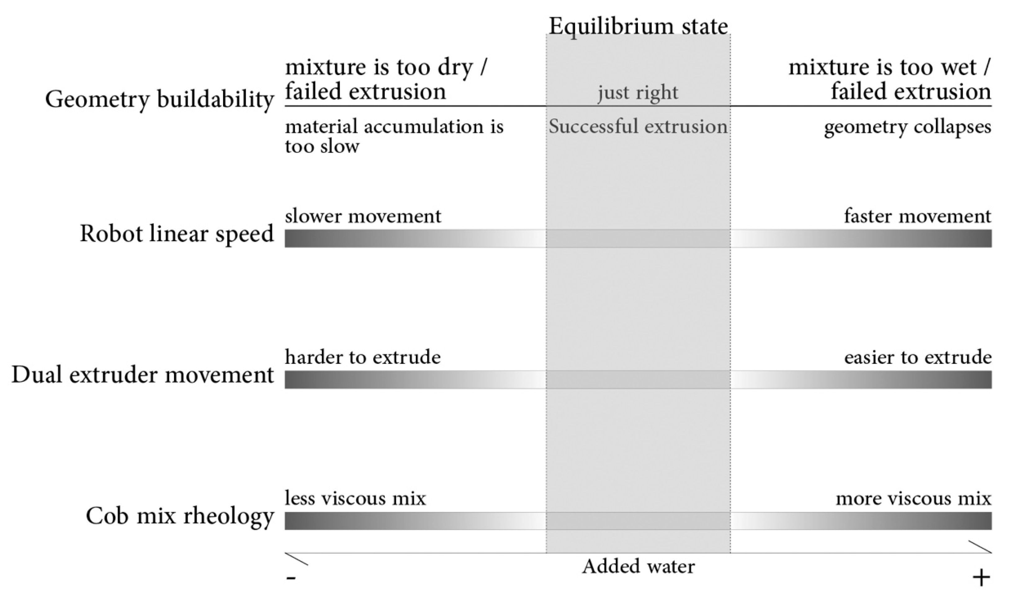
  • The pre-extrusion phase began by breaking the subsoil into smaller portions and transporting it from the storage area outside to the robotic lab, where it was spread out to dry. Once dried, it was crushed into smaller pieces using rubber mallets and then filtered through a 10 mm sieve. The subsoil used for the project was obtained in two batches from the same farmland near Cardiff. Several jar tests were conducted to determine the clay content. Despite being sourced from the same farm, the soil had variable clay content: the first subsoil batch had a clay content of 1.5 parts to 5 parts of sand/silt, while the second batch had a clay content of 3 parts to 5 parts of sand/silt. The dry material was arranged in batches consisting of 12 kg of subsoil and 35 g of manually cut straw measuring an average of 1.5 to 2.5 cm in length. Due to water usage restrictions in the lab, the wet mixture was prepared in the adjacent wet-casting room and stored in covered buckets in the lab. Refer to Figure 6 and Figure 7 for the dry and wet cob-like mixture preparation process. Over time and through repeated experiments, an intuition was developed to achieve the correct texture that balances a mixture of fluidity and viscosity, ensuring a smooth material extrusion and facilitating buildability and shape definition during the printing process. Drop tests were performed throughout the process. In the later stages, a standardised measuring cup of 250 mL ensured the use of consistent amounts of soil. The soil sample was shaped into a ball and dropped from a height of 40 cm onto a 50 mm grid. Experimentation revealed that a diameter of 115 to 120 mm indicated a suitable consistency for the cob mixture in the system. The amount of sieved subsoil and straw remained constant, while the quantity of water varied based on the drop test results (refer to Figure 8). Before filling the tubes, the material was checked using the drop test and adjusted accordingly. This process ensured a mixture with consistent rheological properties, allowing for better control of workability and resolving issues related to material overflow, underflow, and fragmented outputs encountered at the start of the research process. It also helped troubleshoot the limitations of the extruder and define a workable mixture recipe. This quantitative measurement approach mitigated the variability in subsoil composition and properties across the two different acquired batches, controlling the rheology of the wet-like cob material at the pre-extrusion stage and thereby ensuring consistent material extrusion and geometry build-up. The material was then manually compacted into 10 cm diameter, 90 cm length tubes to eliminate air gaps. Filled tubes were covered and stored horizontally to minimise settling. If the material remained in the tubes for more than two days, it was removed, readjusted, and then refilled back into the tubes;
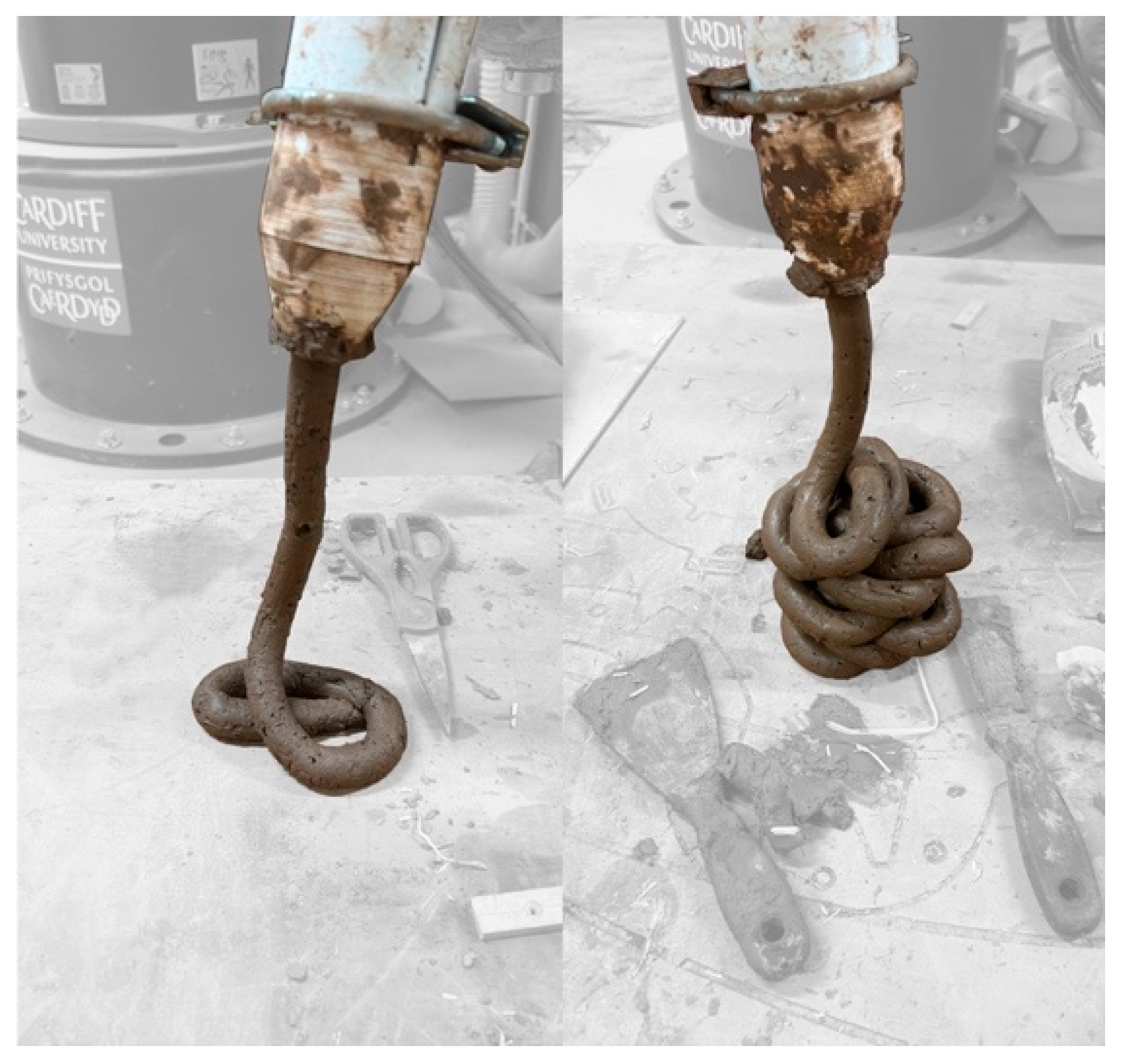
  • The extrusion phase involved the extrusion and printing process of the wet material. It focused on material behaviour during system operation. The process began by loading the tubes into the dual extruder, with each hose containing 1.8 times the amount of the soil mixture held in the tube. This posed a challenge as the loaded material was not the same as the extruded one. As such, it was important to seal both ends of the system to minimise moisture evaporation. Material behaviour was evaluated based on two parts: a. Flow and movement speed in the tube and hose in relation to the push force by the plate attached to the moving rod, and b. Consistency, extrusion, and buildability at the nozzle end held by the robotic arm. The sausage or roll test mentioned in the literature [2] was substituted with observing the material behaviour flow from the nozzle positioned at a distance of approximately 20 cm from the printing plate (refer to Figure 9). Overly fluid mixtures, though easily extruded, were found to have poor buildable geometry. On the other hand, using a more solid mix caused the three-phase 0.75 kW to come to a complete stop. Increasing the amount of fibres used altered the resistance and also reduced the flow movement of the mixture. Additionally, the height at which the material was deposited influenced the path and direction of the hose, thus affecting the material-extrusion speed. To calibrate the above, the rheology of the cob mix was controlled to achieve the identified suitable level of fluidity to work with the dual extruder. The inputted extruder speed was 280 mm/s. However, the actual working speed highly varied depending on the consistency of the extruded material. Through observation, data collection, and analysis, the optimum robot speed was identified at 150 mm/s. The researcher then interactively reduced the speed in response to the material behaviour, starting with quarter intervals and refining it further with 5% reduction steps. The latter gave the researcher the needed control over the operation, enabling a digital sculpting process reminiscent of the craftsmanship associated with traditional cob work. It was observed that the optimum behaviour was achieved when the robot operated between 75% and 25% of its inputted speed (210 mm/s–70 mm/s). The variation accounted for differences in the mixture due to human factors or unavoidable drying processes in the tube or hose when the system was not operated for two days. It also accommodated for the slight variation in material behaviour when deposited at different angles and heights;
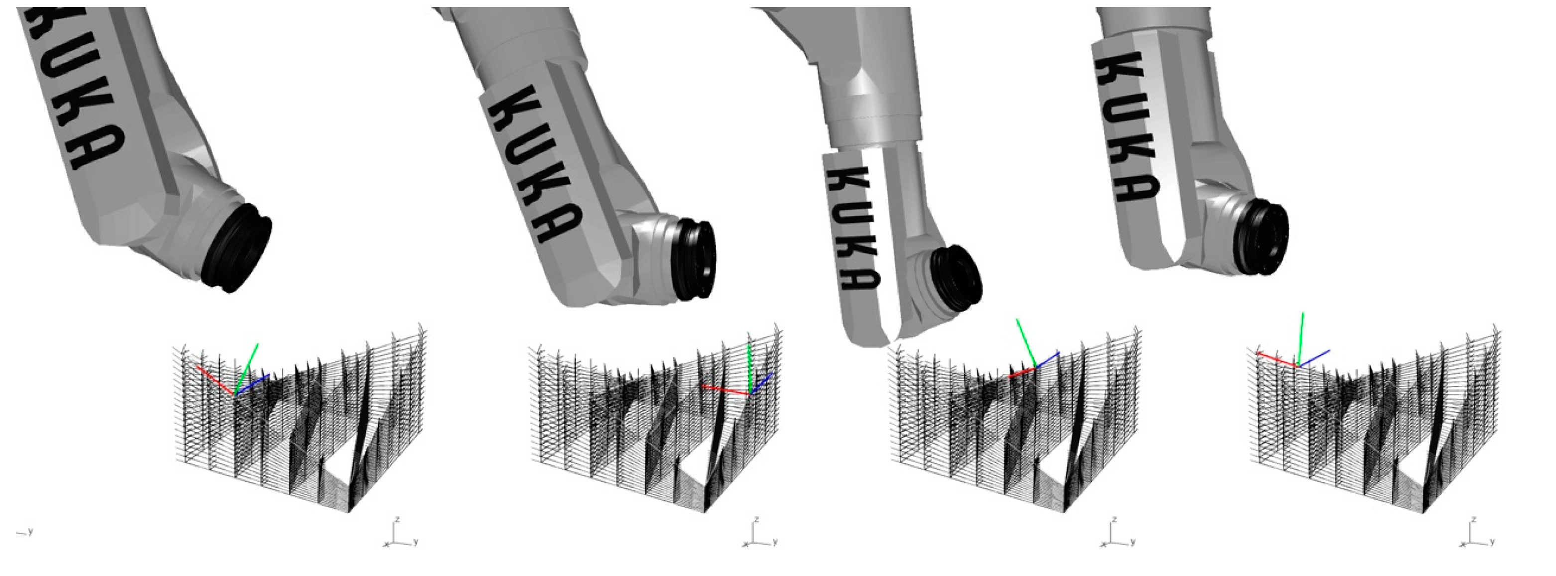
  • Post-extrusion refers to the behaviour of the material once it is extruded from the nozzle and deposited on the tool path according to the geometry design. When planning the toolpath, it was ensured that the perpendicular distance between any two points on two consecutive toolpaths ranged between 5 and 15 mm. The variation in layer height, combined with controlled material overlap, allowed for the exploration and, subsequently, the formation of nonplanar geometries. The material was deposited perpendicular to the toolpath and thus compressed in the same perpendicular direction, which contributed to the overall geometric stability and structural integrity (refer to Figure 10). The relatively small size of the nozzle facilitated digitally sculpted geometrical paths. Due to the varied heights of the geometry, a natural level of material overlap occurred between consecutive layers. However, the overlap was avoided within the same toolpath on any single layer to prevent excess material deposition. Additionally, the layers were alternately reversed to ensure a continuous, non-overlapping printing path. While some case studies recommended against reversing the toolpath to allow the cob material to harden and settle before the next layer [40], the experiments conducted in the lab did not show any noticeable disadvantage in material settling when reversing the nozzle direction in the subsequent layers. This observation informed the design of nonplanar geometry for the pieces.

3.4. Prototyping and Outputted Geometry

Presented are the outputted geometry as printed cob prototypes during the research period. (Refer to Figure 11) The research investigation produced several modules and tested one assembly structure in the form of an arch. The arch modules were manually assembled before they were completely dry, using wet cob as mortar. No other materials or adhesives were used. The approach ensured material consistency and uniform geometrical properties. As the modules dried in their assembled arch formation, they bonded together as a single entity, held in place by the forces dictated by the geometry itself. This is seen as a conceptual proof of possible structural and non-structural cob geometrical formations. Other future examples could possibly include interior and/or exterior cladding systems, non-load-bearing walls, and other various interior elements.
A very close association was observed between the used cob mix rheology, the robot linear speed, and the dual-extruder movement. (Refer to Figure 12) Material that was too wet or too dry failed to extrude. An in-between state presented the right level of workability and was referred to as an equilibrium state by the research team. The study was conducted through a close analysis and observation of the system, the material behaviour, and the output geometry formation while changing one variable at a time. For example, for the same cob mix and dual-extruder movement, several linear robotic speeds were tested and evaluated based on the success or failure of the outputted geometry. Depending on the result, a more complex geometry was tested, or a different consistency of cob mix rheology was tried out. The material path length was dictated by the tube; the hose length and the 25 mm nozzle diameter remained constant throughout. Through a trial-and-error observational method of working, an equilibrium state was devised within the system and lab parameters.
The toolpath for the nonplanar geometry was designed as continuous to accommodate the continuous material flow within the system. The trajectory guiding the robot and, consequently, the nozzle movement was digitally crafted as non-parallel in response to the geometrical design and intended shape. (Refer to Figure 13) It was ensured that the minimum and maximum distance between any consecutive lines in the vertical direction ranged between 6 and 15 mm. This allowed for variation in the geometry design while retaining the compactness of the material through the nozzle. At 6 mm, the layers were wider than those at 15 mm. Additionally, the robot movement was designed perpendicular to its toolpath while maintaining the appropriate direction of the nozzle to maintain the material flow. The robot movement during the process embodied a complex involvement of all its 6-axises, yet also responded to a complex limitation and restrictions imposed by the direction and the length of the two held hoses. Lengthening the hoses was not an option, as it increased the length of the wet material needed to travel, thus significantly increasing the required force from the extruder. As the research progressed, the prototypes increased in their complexity and achieved various combinations of inclinations, concave, and convex curvatures. The printing process was categorised into three processes, all printed using the same dual extruder system. Depending on the geometrical complexity, one or several printing processes were used:
  • Continuous printing using several tubes. Even though, from the operational perspective, continuous, uninterrupted prints could be achieved by sequentially changing the cartridges in the extruder, this approach proved to be unviable as the geometry sagged under its own weight. This was due to the material viscosity and the extruder’s limitations in handling harder mixes, which restrained the reachable height of the printed geometry;
  • Interval-continuous printing was adopted as an alternate approach to achieve continuity. The printing process was paused to allow the deposited material to settle and harden, with the settling time ranging from 12 to 24 h. After the settling period, the model was placed in the same position, and the printing process was resumed from the exact point where it was stopped. It was observed that the intermittent printing process facilitated better control and enabled the outputting of more complex nonplanar geometries. However, one drawback of this approach is the extended overall duration of the printing process and having to plan the process over several days;
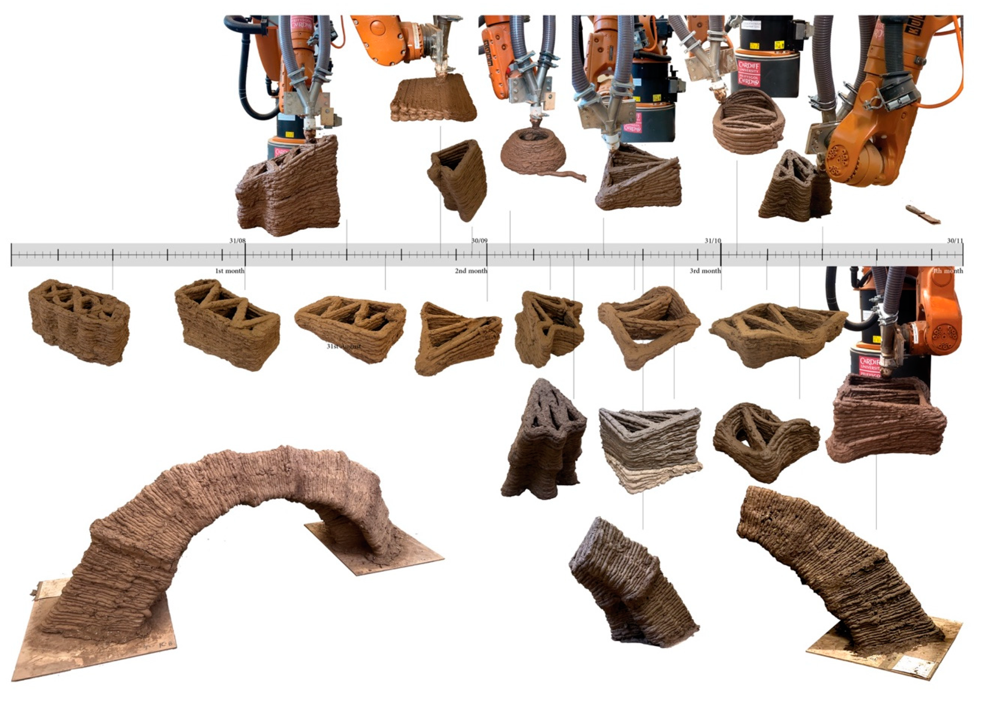
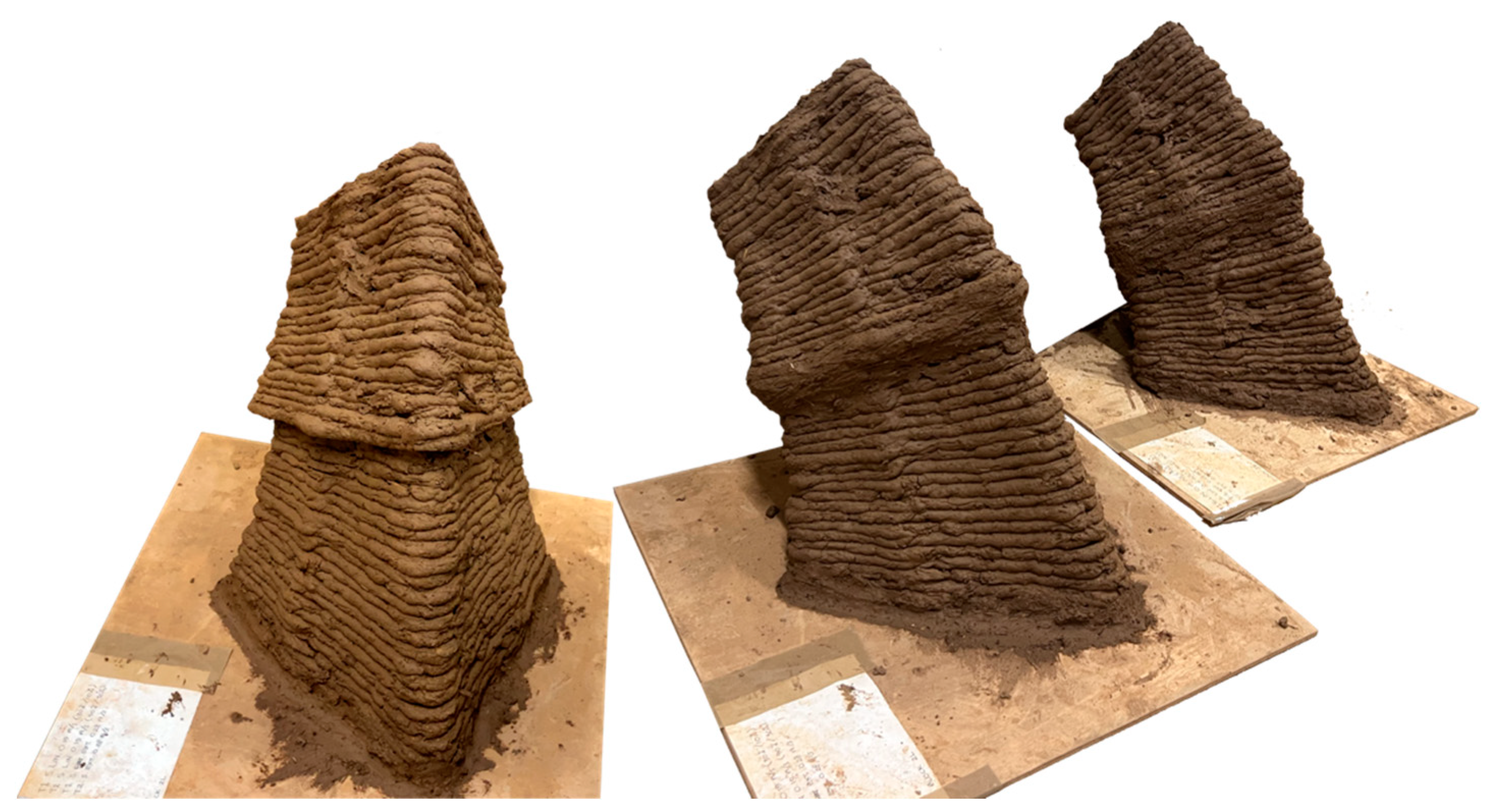
  • Modular printing is a sequential process that involves printing pre-planned segments separately and then joining them to form a more complex geometry. It was observed that the drying process, accompanied by geometry shrinkage, is a complex three-dimensional phenomenon that depends on the volumetric positioning of the geometry in relation to the gravitational force and its own weight. The digitally modelled geometries, which had the same dimensions in the wet state, diverged in shape as they transitioned into the dry state. The same shapes and surfaces underwent changes in formation and were altered depending on their positioning during drying. Assembly of the printed segments was carried out when the geometry had passed the wet stage and thus could be moved around. Figure 14 illustrates three examples of two-geometrical assemblies. The prototype on the left consists of two printed pieces assembled after they had completely dried out. The variation in geometry resulted from the material settling during the drying process. The prototypes in the middle and on the right were assembled at different durations after the wet stage but before complete dryness, resulting in smoother geometrical transitions. In the latter case, the drying process continued after assembly, leading to a more homogeneous final outcome. Therefore, it is important to plan the printing times and drying durations of all segments and strategise the assembly order. For the geometric assemblies, a wet cob was used as mortar to hold the pieces together, eliminating the need for any additional substances and ensuring material homogeneity. When designing the geometries and assemblies, the properties of cob as a material were taken into consideration, focusing on geometries that work well in compression. In the assembled arch prototype, the inner compression forces contributed to its overall stability. For more complex geometrical formations, it will be necessary to codify the three-dimensional shrinkage to accurately assess structural forces, thus ensuring a between geometric fidelity and structural integrity.

4. Discussion and Conclusions

The paper examines nonplanar cob robotic printing and tests its implementation through prototyping. It establishes an equilibrium state with the parameters in the lab and utilises present constraints to generate controlled spatial geometrical exploration. Variation and inconsistencies are overcome through a choreographed collaboration between the system and the researcher, as the robot’s movement is adjusted in response to the deposited material behaviour. By combining the traditional material cob with modern robotic fabrication technology, this research lays the foundation for a novel cob language that is robotically sculpted, thus opening up new possibilities for entirely new tectonics, geometries, and building formations.
The results demonstrate that the successful integration of cob with robotic processes can produce complex nonplanar geometries, proving the feasibility of this approach. The experimental findings show that controlling the rheology of the cob mix, adjusting the robotic extrusion parameters, and using interval-continuous printing methods allow for more stable and intricate designs. This process enabled the creation of a prototype arch, serving as proof of concept for the structural potential of robotically printed cob elements.
The research also highlights the importance of optimising the extruder’s stability and the robot’s movement to enhance the printing process’s efficiency and reliability. The ability to manipulate cob rheology and robotic parameters suggests significant potential for future applications, including more complex architectural structures.
However, the study is limited by the fact that the extruder used is a prototype, which presents challenges in terms of stability and consistency. The prototype’s instability can affect the precision and reliability of the extrusion process, leading to variations in material deposition and print quality. Additionally, the extruder’s current design may not fully accommodate the range of material viscosities and resistances encountered during real-world applications. These limitations underscore the need for further development and refinement of the extruder to ensure consistent performance and scalability for larger-scale projects.
The following three recommendations reflect on some of the challenges faced in the current research setting and provide insights for the next phase:
  • Transforming the subsoil into a wet cob mix is an arduous and repetitive process that could be automated;
  • The instability of the dual-extruder and its variable running speed, based on the material resistance, are important aspects to resolve. The research would benefit from having a controlled, stable pushing force that can be applied to the material, allowing for consistent movement at the same speed, regardless of its wet mix rheology;
  • There is a need to optimise the robot’s movement by increasing its range while maintaining the fluidity and stability of the material flow.
It is imperative for the next research steps to focus on resolving the aforementioned limitations. Doing so would enable a higher level of control over the process. Further work should include examining the devised work methodology using different wet cob-like mixes from various geographic locations, as well as experimenting with different fibre types. Additionally, the research should aim to incorporate a more intelligent feedback system that surpasses the mere observation of the researcher to include capabilities that encompass design intent and material behaviour. Another possible direction is to advance the method of preparing the printable material mixture, ensuring consistent material properties. Both approaches are foreseen to facilitate more complex spatial movements and contribute to a more intelligent and responsive system.

Author Contributions

L.A. was responsible for conducting all research activities, including data collection, experimentation, analysis, and manuscript preparation, in addition to securing academic grants. W.J. provided supervision, guidance, and advice throughout the study and played a key role in facilitating the collaboration between the two universities. M.S. played an instrumental role in securing the academic grants and the funding necessary for the research project. All authors have read and agreed to the published version of the manuscript.

Funding

This research was funded by Zayed University Provost’s Research Fellowship Award R21046 and by Zayed University Research Cluster Award R20144.

Data Availability Statement

The authors confirm that the data supporting the findings of this study are available within the article.

Acknowledgments

Special thanks to the College of Arts and Creative Enterprises, Zayed University. Sincere gratitude to The Welsh School of Architecture, Cardiff University. Extended gratitude to the Research Assistants, Sapta Sunusae, Darshan Chavan, Selda Pourali Behzad, and Omar Iqbal, and to the students of the 2022 MSc Computational Methods in Architecture for their invaluable assistance.

Conflicts of Interest

The authors declare no conflicts of interest.

References

  1. Rogue, C. House of Earth: A Complete Handbook for Earthen Construction; CreateSpace Independent Publishing Platform: Scotts Valley, CA, USA, 2016; ISBN 9781530642816. [Google Scholar]
  2. Weismann, A.; Bryce, K. Building with Cob: A Step-by-Step Guide; Green Book: Cambridge, UK, 2006; ISBN 9781903998724. [Google Scholar]
  3. Steen, B.; Athena, S. Built by Hand: Vernacular Buildings around the World, 1st ed.; Baird, M., Ed.; Gibbs Smith: Kaysville, UT, USA, 2004; ISBN 9781586852375. [Google Scholar]
  4. Evans, I.; Smith, M.G.; Smiley, L. The Hand-Sculpted House. In A Practical and Philosophical Guide to Building a Cob Cottage; Chelsea Green Publishing: White River Junction, VT, USA, 2002. [Google Scholar]
  5. Aubert, J.-E.; Faria, P.; Maillard, P.; Ouedraogo, K.A.J.; Ouellet-Plamondon, C.; Prud’homme, E. Characterization of Earth Used in Earth Construction Materials. In Testing and Characterisation of Earth-Based Building Materials and Elements; RILEM State-of-the-Art Reports; Fabbri, A., Morel, J.C., Aubert, J.E., Bui, Q.B., Gallipoli, D., Reddy, B.V.V., Eds.; Springer: Berlin/Heidelberg, Germany, 2022; pp. 17–25. [Google Scholar]
  6. Fabbri, A.; Morel, J.-C.; Aubert, J.-E.; Bui, Q.-B.; Gallipoli, D.; Reddy, B.V.V. (Eds.) Testing and Characterisation of Earth-Based Building Materials and Elements; RILEM State-of-the-Art Reports; Springer International Publishing: Berlin/Heidelberg, Germany, 2022; Volume 35, ISBN 978-3-030-83296-4. [Google Scholar]
  7. Azil, A.; Le Guern, M.; Touati, K.; Gomina, M.; Sebaibi, N.; Boutouil, M.; Streiff, F.; Goodhew, S.; Louahlia, H. Construction Field Monitoring of a COB Prototype Building. In Proceedings of the 4th International Conference on Bio-Based Building Materials, Barcelona, Spain, 16–18 June 2021; pp. 458–465. [Google Scholar]
  8. Niroumand, H.; Zain, M.F.M.; Jamil, M. A Guideline for Assessing of Critical Parameters on Earth Architecture and Earth Buildings as a Sustainable Architecture in Various Countries. Renew. Sustain. Energy Rev. 2013, 28, 130–165. [Google Scholar] [CrossRef]
  9. Morris, W. Devon Historic Buildings Trust; DHBT: Devon, UK, 1992; Available online: https://www.joostdevree.nl/bouwkunde2/jpgl/leem_11_lemen_gebouwen_in_devon_1_geschiedenis_enz_www_devonearthbuilding_com.pdf (accessed on 10 June 2024).
  10. Watson, L.; McCabe, K. The Cob Building Technique: Past, Present and Future. Inf. Constr. 2011, 63, 59–70. [Google Scholar] [CrossRef]
  11. Jaquin, P.; Augarde, C. Earth Building: History, Science and Conservation; IHS BRE Press: Watford, UK, 2012. [Google Scholar]
  12. Quagliarini, E.; Stazi, A.; Pasqualini, E.; Fratalocchi, E. Cob Construction in Italy: Some Lessons from the Past. Sustainability 2010, 2, 3291–3308. [Google Scholar] [CrossRef]
  13. Bardel, P.; Rioult, J.-J. Les Premieres Formes de Construction En Bauge Dans Le Bassin de Rennes. The First Forms of Cob Construction in the Rennes Area. In L’architecture en Bauge en Europe (Cob Building in Europe); Parc Naturel Regional des Marais du Cotentin et du Bessin: Isigny-sur-Mer, France, 2006; pp. 151–172. [Google Scholar]
  14. Bavay, G. Trente Annees d’investigations Sur La Bauges En Wallonie (Belgique). La Bauge Dans Le Contexte Des Architectures de Terre. Historiographie et Tendances. (Thirty Years of Investigating Con in the Walloon Area of Belgium. Cob within the Context of Earth-Based Architecture. Historiography and Trends). In L’architecture En Bauge En Europe (Cob building in Europe); Parc Naturel Regional des Marais du Cotentin et du Bessin: Isigny-sur-Mer, France, 2006; pp. 93–116. [Google Scholar]
  15. Ziegert, C. Analysis of Material, Construction and Damage in Historical Cob Buildings in Central Germany. In Proceedings of the Terra 2000: 8th International Conference on the Study and Conservation of Earthen Architecture, Devon, UK, 6–11 May 2000; James & James: London, UK, 2000. [Google Scholar]
  16. Aurenche, O.; Klein, A.; de Chazelles, C.-A.; Hubert, G. Essai de Classification Des Modalités de Mise En Œuvre de La Terre Crue En Parois Verticales et de Leur Nomenclature. In Les Cultures Constructives de la Brique Crue; Editions Espérou; ENSAM: Paris, France, 2008; pp. 13–34. [Google Scholar]
  17. Joshi, O.P. Earthen Architecture in Indian Tribes. In Proceedings of the Terra 2008: The 10th International Conference on the Study and Conservation of Earthen Architectural Heritage, Bamako, Mali, 1–5 February 2008; Getty Publications: Los Angeles, CA, USA, 2008; pp. 109–113. [Google Scholar]
  18. Norton, J. Building with Earth: A Handbook; ITDG Publishing: Rugby, UK, 1986; ISBN 9780946688333. [Google Scholar]
  19. Stacked Earth (Cob). Available online: https://www.earth-auroville.com/stacked_earth_en.php (accessed on 8 December 2022).
  20. Ford, M.; El Kadi, H.; Watson, L. The Relevance of Gis in the Evaluation of Vernacular Architecture. J. Archit. Conserv. 1999, 5, 64–75. [Google Scholar] [CrossRef]
  21. Harries, R.; Saxton, B.; Coventry, K. The geological and geotechnical properties of earth material from central devon in relation to its suitability for building in “COB”. Proc. Ussher Soc. 1995, 8, 441–444. [Google Scholar]
  22. Reddy, B.V.V.; Morel, J.-C.; Faria, P.; Fontana, P.; Oliveira, D.V.; Serclerat, I.; Walker, P.; Maillard, P. Codes and Standards on Earth Construction. In Testing and Characterisation of Earth-Based Building Materials and Elements; Springer: Berlin/Heidelberg, Germany, 2021; pp. 243–259. ISBN 9783030832971. [Google Scholar]
  23. Goodhew, S.; Boutouil, M.; Streiff, F.; Le Guern, M.; Carfrae, J.; Fox, M. Improving the Thermal Performance of Earthen Walls to Satisfy Current Building Regulations. Energy Build 2021, 240, 110873. [Google Scholar] [CrossRef]
  24. Ben-Alon, L.; Loftness, V.; Harries, K.A.; Cochran Hameen, E. Integrating Earthen Building Materials and Methods into Mainstream Construction Using Environmental Performance Assessment and Building Policy. IOP Conf. Ser. Earth Environ. Sci. 2019, 323, 012139. [Google Scholar] [CrossRef]
  25. Keefe, L. Earth Building: Methods and Materials, Repair and Conservation; Taylor & Francis Ltd.: Abingdon, UK, 2005; ISBN 9780415323222. [Google Scholar]
  26. Alqenaee, A.; Memari, A. Experimental Study of 3D Printable Cob Mixtures. Constr. Build Mater. 2022, 324, 126574. [Google Scholar] [CrossRef]
  27. Gomaa, M.; Carfrae, J.; Goodhew, S.; Jabi, W.; Veliz Reyes, A. Thermal Performance Exploration of 3D Printed Cob. Archit. Sci. Rev. 2019, 62, 230–237. [Google Scholar] [CrossRef]
  28. Veliz Reyes, A.; Jabi, W.; Gomaa, M.; Chatzivasileiadi, A.; Ahmad, L.; Wardhana, N.M. Negotiated Matter: A Robotic Exploration of Craft-Driven Innovation. Archit. Sci. Rev. 2019, 62, 398–408. [Google Scholar] [CrossRef]
  29. Moretti, F. 3D Printed Houses for a Renewed Balance between Environment and Technology. Available online: https://www.3dwasp.com/en/3d-printed-houses-for-a-renewed-balance-between-environment-and-technology/ (accessed on 8 December 2022).
  30. International Energy Agency. Towards a Zero-Emissions, Efficient and Resilient Buildings and Construction Sector. In UN Environment Program 2019 Global Status Report for Buildings and Construction; International Energy Agency: Paris, France, 2019; ISBN 9789280737684. [Google Scholar]
  31. Alhumayani, H.; Gomaa, M.; Soebarto, V.; Jabi, W. Environmental Assessment of Large-Scale 3D Printing in Construction: A Comparative Study between Cob and Concrete. J. Clean. Prod. 2020, 270, 122463. [Google Scholar] [CrossRef]
  32. Mitropoulou, I.; Bernhard, M.; Dillenburger, B. Nonplanar 3D Printing of Bifurcating Forms. 3D Print. Addit. Manuf. 2022, 9, 189–201. [Google Scholar] [CrossRef] [PubMed]
  33. Piker, D.; Maddock, R. Continuous Robotic Spatial 3D Printing of Topologically Irregular Space Frames. In Proceedings of the Design Modeling Symposium, Berlin, Germany, 23–25 September 2009; Springer: Berlin/Heidelberg, Germany, 2009; pp. 502–516. [Google Scholar] [CrossRef]
  34. Im, H.C.; Alothman, S.; Castillo, J.L.G. Responsive Spatial Print. Clay 3D Printing of Spatial Lattices Using Real-Time Model Recalibration. In Proceedings of the 38th Annual Conference of the Association for Computer Aided Design in Architecture (ACADIA), Mexico City, Mexico, 18–20 October 2018; pp. 286–293. [Google Scholar]
  35. Yu, L.; Luo, D. Mesh Optimisation for Spatial Wireframe Robotic 3D Printing. Int. J. Rapid Manuf. 2018, 7, 169. [Google Scholar] [CrossRef]
  36. Laarman, J.; Jokic, S.; Novikov, P.; Fraguada, L.E.; Markopoulou, A.; Gramazio, F.; Kohler, M.; Langenberg, S. Anti-Gravity Additive Manufacturing. In Fabricate 2014: Negotiating Design & Making; Gramazio, F., Kohler, M., Langenberg, S., Eds.; UCL Press: London, UK, 2017; pp. 192–197. [Google Scholar]
  37. Sparrow, N. What Is Robotic 3D-Printing Extrusion, and What Is It For? Plastics Today, February 2017. [Google Scholar]
  38. Jahanmahin, R.; Masoud, S.; Rickli, J.; Djuric, A. Human-Robot Interactions in Manufacturing: A Survey of Human Behavior Modeling. Robot. Comput. Manuf. 2022, 78, 102404. [Google Scholar] [CrossRef]
  39. Bernard, M.; Architect. R + D Awards. 9 August 2021. Available online: https://www.architectmagazine.com/awards/r-d-awards/award-robotic-constructionthe-glass-vault_o (accessed on 10 June 2024).
  40. Kofer, D.; Bergner, C.; Deuerlein, C.; Schmidt-Vollus, R.; Heß, P. Human-Robot-Collaboration: Innovative Processes, from Research to Series Standard. Procedia CIRP 2020, 97, 98–103. [Google Scholar] [CrossRef]
  41. Matheson, E.; Minto, R.; Zampieri, E.G.G.; Faccio, M.; Rosati, G. Human-Robot Collaboration in Manufacturing Applications: A Review. Robotics 2019, 8, 100. [Google Scholar] [CrossRef]
  42. Hentout, A.; Aouache, M.; Maoudj, A.; Akli, I. Human–Robot Interaction in Industrial Collaborative Robotics: A Literature Review of the Decade 2008–2017. Adv. Robot. 2019, 33, 764–799. [Google Scholar] [CrossRef]
  43. ETH Zurich World Economic Forum. 26 May 2018. Available online: https://www.weforum.org/agenda/2018/03/robotic-collaboration-in-timber-construction (accessed on 10 June 2024).
  44. Palazzo, A.; Macek, D. Contour Crafting Technology: The Toothpaste for Constructions. Bus. IT 2021, 11, 51–59. [Google Scholar] [CrossRef]
  45. Khoshnevis, B.; Kazemian, A. Contour Crafting: A Revolutionary Platform Technology. Prod. Appl. 2020, 48–53. [Google Scholar]
  46. Gomaa, M.; Jabi, W.; Veliz Reyes, A.; Soebarto, V. 3D Printing System for Earth-Based Construction: Case Study of Cob. Autom. Constr. 2021, 124, 103577. [Google Scholar] [CrossRef]
  47. Gin, Y.; Haddad, K.; Jabi, W.; Shah, D.U.; Ramage, M.H. Robotic 3D Printing with Earth: A Case Study for Optimisation of 3D Printing Building Blocks. In Proceedings of the IASS 2022 Symposium Affiliated with APCS 2022 Conference Innovation—Sustainability—Legacy, Beijing, China, 19–22 September 2022; pp. 3206–3217. [Google Scholar]
  48. Khoshnevis, B. Automated Construction by Contour Crafting—Related Robotics and Information Technologies. Autom. Constr. 2004, 13, 5–19. [Google Scholar] [CrossRef]
  49. Labonnote, N.; Rønnquist, A.; Manum, B.; Rüther, P. Additive Construction: State-of-the-Art, Challenges and Opportunities. Autom. Constr. 2016, 72, 347–366. [Google Scholar] [CrossRef]
  50. Kim, D.M. Illumin Article. Writing 340. 2013. Available online: http://illumin.usc.edu/assets/submissions/755/Contour%20Crafting%20revision.pdf (accessed on 10 June 2024).
  51. Khoshnevis, B.; Hwang, D.; Yao, K.-T.; Yeh, Z. Mega-Scale Fabrication by Contour Crafting. Int. J. Ind. Syst. Eng. 2006, 1, 301–320. [Google Scholar] [CrossRef]
  52. Craveiro, F.; Duarte, J.P.; Bartolo, H.; Bartolo, P.J. Additive Manufacturing as an Enabling Technology for Digital Construction: A Perspective on Construction 4.0. Autom. Constr. 2019, 103, 251–267. [Google Scholar] [CrossRef]
  53. Winsun Yingchuang Building Technique. Available online: http://www.winsun3d.com/En/About/ (accessed on 8 December 2022).
  54. COBOD. The Bod. Available online: https://cobod.com/projects-partners/the-bod-building/#:~:text=Europe’s%20first%203D%20printed%20building%20is%20located%20in%20Copenhagen%2C%20Denmark,conventional%20construction%20methods%20of%20today (accessed on 8 December 2022).
  55. CyBe 3D Studio 2030. Available online: https://cybe.eu/cases/3d-studio-2030/ (accessed on 8 December 2022).
  56. Thomsen, M. Mail Online. 6 February 2020. Available online: https://www.dailymail.co.uk/sciencetech/article-7975233/Worlds-biggest-3D-printed-building-opens-Dubai-6-900-square-foot-government-office.html (accessed on 10 June 2024).
  57. Giannakopoulos, S. Pylos Project-Robotic 3D Printing of Clay. The Institute for Advanced Architecture of Catalonia (IAAC). 2015. Available online: https://iaac.net/project/pylos/ (accessed on 8 December 2022).
  58. Cabay, E.; Dubor, A. TerraPerforma Project. 3D Printed Performative Wall. Available online: https://iaac.net/project/terraperforma/ (accessed on 8 December 2022).
  59. Dubor, A.; Cabay, E.; Marengo, M.; Chadha, K.; Moreno, S. Digital Adobe. Available online: https://iaac.net/project/digital-adobe/ (accessed on 8 December 2022).
  60. Chiusoli, A. The First 3D Printed House with Earth|Gaia. Available online: https://www.3dwasp.com/en/3d-printed-house-gaia/ (accessed on 8 December 2022).
  61. WASP and Mario Cucinella Architects MCA. TECLA. 2021. Available online: https://www.3dwasp.com/en/3d-printed-house-tecla/ (accessed on 8 December 2022).
  62. Moretti, F. WASP 3D Prints a Unique Concept Store in Collaboration with Dior. Available online: https://www.3dwasp.com/en/3d-printed-pop-up-store-wasp-dior/ (accessed on 8 December 2022).
  63. Lazzari, G. Crowdfunding for the House of Dust. Available online: https://www.3dwasp.com/en/crowdfunding-for-the-house-of-dust/ (accessed on 8 December 2022).
  64. Severi, A. Itaca: The Self-Sufficient and Eco-Sustainable 3D Printed House. Available online: https://www.3dwasp.com/en/itaca-the-self-sufficient-and-eco-sustainable-3d-printed-house/ (accessed on 8 December 2022).
  65. Chiusoli, A. 3D Printed Earth Wall with Embedded Staircase. Available online: https://www.3dwasp.com/en/3d-printed-wall/ (accessed on 10 June 2024).
  66. Polvi, F.; Bryson, Z. 152 Travessera de Gràcia. Available online: https://www.iaacblog.com/programs/152-travessera-de-gracia/ (accessed on 8 December 2022).
  67. Emerging Objects. Mud Frontiers: Part II. 2019. Available online: http://emergingobjects.com/project/mud-frontiers-part-ii/ (accessed on 8 December 2022).
  68. Emerging Objects Casa Covida. Available online: https://www.rael-sanfratello.com/made/casa-covida (accessed on 8 December 2022).
  69. Perrot, A.; Rangeard, D.; Courteille, E. 3D Printing of Earth-Based Materials: Processing Aspects. Constr. Build. Mater. 2018, 172, 670–676. [Google Scholar] [CrossRef]
  70. Perrot, A.; Rangeard, D.; Lecompte, T. Field-Oriented Tests to Evaluate the Workability of Cob and Adobe. Mater. Struct. 2018, 51, 54. [Google Scholar] [CrossRef]
  71. Bee, B. The Cob Builders Handbook. You Can Hand-Sculpt Your Own Home; Chelsea Green: White River Junction, VT, USA; Victoria, BC, Canada, 1997. [Google Scholar]
Figure 1. Robotic lab working areas. The length of the two hoses connected to the two-way aluminium channel held by the robot influences the distance the wet cob travels and, consequently, the required extruding force.
Buildings 14 02589 g001
Figure 2. The rubber seal was added to the extruder’s push plate to force the material forward movement.
Buildings 14 02589 g002
Figure 3. Diameter reduction along the wet cob dual extrusion path.
Buildings 14 02589 g003
Figure 4. Extruder and robot integrated into one lab setting at the Welsh School of Architecture, Cardiff University.
Buildings 14 02589 g004
Figure 5. A methodological diagram shows the relationship between the printing process and material preparation.
Buildings 14 02589 g005
Figure 6. The dry cob-like mixture preparation process involves a series of steps depicted from left to right: (a) Spreading the wet subsoil for drying. (b) Sorting and pulverising the dried subsoil using rubber mallets. (c) Sieving the crushed subsoil through a 10 mm sieve. (d) Combining the sieved subsoil with cut straw to produce the cob-like dry mixture. Water is subsequently introduced to yield the cob-like wet mixture.
Buildings 14 02589 g006
Figure 7. The wet cob-like preparation process encompasses four sequential steps: (a) Once water is added, the wet cob-like mixture is stored in sealed buckets. (b) The water quantity is readjusted using a controlled grid-measured drop ball test. (c) The wet cob-like mixture is loaded into the tubes and manually compressed and compacted. (d) The tubes are then loaded into the bespoke extruder, which is part of the continuous cob robotic printing process.
Buildings 14 02589 g007
Figure 8. Wet-like cob recipe, ingredients, and ratios, distinguishing the constant and variable ingredients.
Buildings 14 02589 g008
Figure 9. The substitution of a traditional sausage soil test with a robotic sausage-like extrusion to check wet-cob material consistency and buildability.
Buildings 14 02589 g009
Figure 10. Extruded material is deposited perpendicularly to the toolpath of the printed geometry.
Buildings 14 02589 g010
Figure 11. Nonplanar spatial prototypes are presented in the chronological order of printing over a four-month period. Selected parts were assembled into an arch.
Buildings 14 02589 g011
Figure 12. A qualitative observational reactive working methodology establishes associations among four parameters inherent to the spatial robotic printing process, aiming to attain an equilibrium state and thereby ensuring the successful printing of nonplanar cob geometry.
Buildings 14 02589 g012
Figure 13. The non-parallel toolpath directs the perpendicular robot, and consequently, the nozzle movement and the wet-cob deposition are guided by the nonplanar geometry design.
Buildings 14 02589 g013
Figure 14. The volumetric variation of the same printed geometry is due to the drying position and duration, as well as the material state during the assembly process.
Buildings 14 02589 g014
Disclaimer/Publisher’s Note: The statements, opinions and data contained in all publications are solely those of the individual author(s) and contributor(s) and not of MDPI and/or the editor(s). MDPI and/or the editor(s) disclaim responsibility for any injury to people or property resulting from any ideas, methods, instructions or products referred to in the content.

