Abstract
This paper presents the development and validation of a new filament-wound CFRP sleeve and resin grout for the efficient anchorage of parallel CFRP wire bundles. Twenty-five-year-old, reused CFRP wires (recovered from two dismantled bridge cables) were examined with regard to any possible drop in strength or stiffness due to aging and then processed into two bridge strengthening cables. The new anchorage and cables were tested to their tensile capacity (giving on average 1.833 MN) in two full-scale instrumented experiments. This being successful, it gave the authors the confidence to manufacture two new 26–30 m long post-tensioning parallel-wire cables, each using 37 of the recovered CFRP wires. Both CFRP parallel-wire cables were finally successfully prestressed to 1 MN (55% of their UTS) in order to strengthen an existing bridge in the Swiss Alps over the river Ilfis in the summer of 2023. This strengthening project is described. The full-scale tests confirmed the durability and strength of the new anchorage system, and the feasibility for reusing valuable CFRP pultrusions for post-tensioning was proven by the successful bridge strengthening carried out. Finally, the project also demonstrated the sustainability potential of CFRP pultrusions. The monitoring data of this bridge project are presented and discussed.
1. Introduction
CFRP (Carbon Fiber Reinforced Polymer) pultrusions are the most efficient composite materials for bearing uniaxial loads. In structural engineering, they are produced by continuously pressing high-strength carbon fibers, which are pre-impregnated with an epoxy resin, through a heated die (typically at 180 °C to 200 °C). Common pultruded CFRP profiles include strips (lamellae), which are used as externally bonded flexural and shear reinforcements (EBR) on substrates such as concrete, steel, or masonry. Another popular profile is round CFRP wires, typically used as internal reinforcement in concrete for prestressing (via the pre-tensioning method, as described in [1]) and for assembling CFRP Parallel Wire Bundle cables (PWB), used in bridge applications [2].
This project investigates whether CFRP pultrusions can be reused once a CFRP-reinforced structure reaches the end of its service life, and it focusses on CFRP residual strength and durability. This investigation must also address the technological challenges posed by the strength anisotropy of pultrusions—often made with pure unidirectional fiber arrangement—which makes the extraction of components such as CFRP post-tensioning cables from structures (e.g., bridges) before demolition a delicate process. After evaluating the integrity of the recovered CFRP pultrusions, new design strengths and moduli must be experimentally determined, and the maximum service stresses for the material must be reassessed, particularly if the CFRP is reused as prestressing reinforcement.
The design guidelines for maximum allowable long-term tensile service stresses for CFRP pultrusions in civil applications (CFRP embedded in concrete) are generally conservative, as CFRP has only a very successful 30-year track record in civil engineering. According to [3], CFRP can tolerate sustained tensile stresses up to 80% of its short-term characteristic strength, referring to the fib Model Code for concrete structures [4]. This code states that, for unidirectional CFRP, the permissible stress level against stress rupture corresponds to at least 80% of its short-term strength for service over a 50-year period. The relaxation of CFRP prestressing elements over 50 years is estimated to range from 2% to 10%, depending on the stress level and environmental factors, with higher carbon fiber content resulting in less relaxation. Reference [4] also notes that a more specific upper limit for sustained stress should be determined through the durability testing of the specific CFRP pultrusion. Furthermore, recent updates suggest a tensile in-service stress limit of 0.56 times the characteristic tensile strength of CFRP pultruded elements [5]. Additionally, a reduction of 21% in the material’s elastic modulus due to viscoelastic creep is recommended for a 50-year service life [3].
ACI guidelines 440-1R (Ref. [6], Table 8.3 on FRP creep rupture stress limits), recommend an in-service sustained stress limit of 0.55 for CFRP bars to account for creep when CFRP is embedded in concrete (not directly exposed to earth and weather). In an early (1997) and comprehensive investigation, Yamaguchi et al. [7] tested 6 mm diameter pultruded carbon fiber reinforced epoxy resin tendons in creep at room temperature using wedge anchors at various load ratios. Their probabilistic analysis of the specimens’ failure times for different sustained tensile load levels allowed them to discover a linear proportionality between the creep strength and the logarithm of the rupture time. Therewith the authors could estimate the average reduction in the creep rupture strength with respect to the initial quasi-static strength and reported an extrapolated 7% strength reduction due to creep for CFRP after 57 years of service for a survival probability of 50%. Few studies have experimentally investigated pultrusions under sustained tensile creep loading for more than one year. For example, ref. [8] tested 8 mm diameter pultruded CFRP tendons with a fiber content of 65% and an epoxy matrix in creep for 1000 h, applying a sustained tensile stress of 69%, 76%, and 85% of the tendon’s tensile strength. Their findings were a CFRP tendon’s residual strength which was 4.54% lower than the quasi-static tensile strength, while the elastic modulus of the tendons increased by 6.99% compared to the short-term modulus due to fiber straightening during tensile creep. In [9], it is stated that CFRP shows excellent creep behavior with very limited creep strain. The authors explain that the creep strain of unidirectional CFRP at room temperature remains under 0.01% after 3000 h at a tensile stress of even 80 percent of the tensile strength. In addition, the 114-year tensile creep strength of CFRP was estimated in [9] to be equivalent to 80–95% of the short-term tensile strength (depending on the carbon fiber type and volume amount). Hence, the available design guidelines must be considered as conservative when compared against available experiments, as recently concluded by Boloux et al. [5].
This paper reports on the reuse of a unique batch of pultruded CFRP wires originally used to build two 91-parallel-wire CFRP cables (each 47.75 m long and with a tensile capacity of 5 MN) for bridge post-tensioning. These cables were in service for 17.5 years and were subjected to the sustained tensile prestress of 1350 MPa in outdoor conditions. In April 2016, the cables were unstressed and extracted from the original bridge. The cables were then stored outdoors for an additional 7.5 years at Empa. In winter 2023, i.e., 25 years after their manufacturing (pultrusion in 1998), the materials were carefully evaluated with the aim to define the remnant strength and permissible prestress levels for a new bridge strengthening. This being successful, in 2023, two lab-scale 37-wire CFRP cables were tested before reusing 2.2 km of wire to manufacture two new bridge post-tensioning cables. The cables made of the reused wires were installed on 23 August 2023, to prestress and reinforce Ilfis Bridge in the Canton of Lucerne in the central Swiss Alps. The findings from this project, including 14 months of monitoring data on the new cables, are discussed in this paper.
2. Materials and Methods
2.1. Background: The Source of Serviced CFRP Pultruded Wires
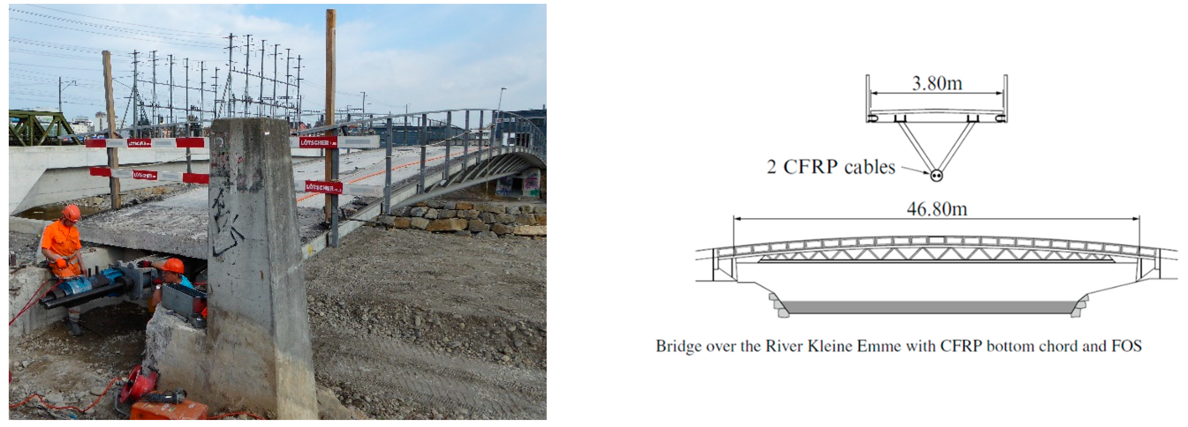
The Kleine Emme Bridge, located in the city of Lucerne, was completed in October 1998 as a steel composite structure designed for pedestrians and bicycles. It was also designed to accommodate an ambulance if necessary (Figure 1, [2]). The bridge featured a reinforced concrete deck supported by a steel space truss, with an overall length of 56 m (including a span of 46.8 m) and a width of 3.8 m. Its tensile flange was constructed as a tubular space truss, terminating in a longitudinal steel channel that housed two prestressed CFRP parallel-wire cables, each measuring 47.75 m in length and exerting a prestressing force of 2.4 MN (Figure 1). These post-tensioning cables were made up of 91 individual pultruded CFRP wires, each 5.08 mm in diameter, arranged in a hexagonal configuration giving a CFRP cable weight of only 3 kg/m. The wires were prestressed to 1350 MPa, which corresponds to 45% of the CFRP’s design tensile strength. At the time of construction, a novel CFRP anchorage technology developed by Empa [10] was employed to anchor the CFRP cables within steel sleeves. The four cable anchorage heads were constructed using zinc-coated steel sleeves with an internal conical profile (100 kg each), into which the 91 CFRP wires were grouted using a special epoxy. This epoxy had a gradually increasing elastic modulus; it was soft at the point of load entry and became progressively stiffer towards the anchor end, with alumina particles incorporated to enhance stiffness (Empa’s gradient anchorage system, [10]).
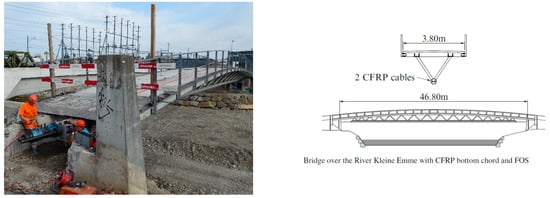
Figure 1.
Former pedestrian bridge over the Kleine Emme [2] (photo taken by Empa in April 2016, during CFRP cable extraction).
In April 2016, after 17.5 years of service, the bridge was dismantled (Figure 1, left) and replaced by a new, longer-span prestressed concrete bridge as part of a new flood protection scheme for the city of Lucerne. A total of 8.7 km of pultruded CFRP wires, valued at approximately EUR 45,000, were returned to Empa following the decommissioning of the bridge.
2.2. Specification of Materials and Assessment of Remnant Properties
The fibers used in 1997/98 for the CFRP wire pultrusion by Stesalit Ltd. in Zullwil, Switzerland were Toray T700 SC (12k rovings) embedded in an epoxy matrix LY556/HY917/DY070 supplied by Ciba-Geigy of Basel in Switzerland. The CFRP wires had an average diameter of 5.08 mm, a nominal fiber volume amount of 70.6% leading to a design tensile strength of 3000 MPa, and a design modulus of 160 GPa in fiber direction. The bridge wire lot was tested by Empa in summer 1998 and consistently fulfilled the strength and modulus criteria (Table 1). An extensive investigation of the residual mechanical and thermal properties of the CFRP wires used in the Kleine Emme Bridge was performed during 2023 by Boloux at al. [5]. To evaluate the potential for reusing the CFRP wires, it was essential to assess their axial strength, modulus, failure strain, and glass transition temperature (Tg) in order to quantify their residual properties and degradation after 25 years of service. The Tg of the recovered CFRP wires was 129.6 °C, measured by differential scanning calorimetry (DSC) in 2023. This is slightly below the Tg of over 140 °C which was specified by Ciba-Geigy 1998 (considering a pultrusion in a 180 °C heated dye with a dwell time of approx. 6 min at 180 °C).

Table 1.
Comparison of tensile properties of Kleine Emme CFRP wires after 25 years in service.
Tensile testing was performed on the same Instron 1251 servo-hydraulic tensile testing machine using a resin grout anchorage system. All tensile specimens had a free length of 400 mm. Table 1 summarizes the results and shows that compared to the data established in 1998, the mean tensile strength of aged wires has decreased by 9.7% in 25 years, while the elastic modulus lies within the statistical scatter. The cause of the strength degradation is still being investigated, with a potential embrittlement of the pultruded epoxy resin suspected as a contributing factor.
For the 25-year-old CFRP (and formerly prestressed) wires recovered from Kleine Emme Bridge, a 99% wire-strength quantile of 2648 MPa can be determined assuming a Gaussian strength distribution (Table 1).
A systematic quality assessment of the wire integrity was performed pragmatically by simple multi-axial bending of the wires to a radius of curvature of approx. 1 m (leading to a bending strain of ±0.25%) to spot surface defects such as delaminations and cracks. An automatic NDT quality assurance procedure would be needed for future reuse projects of CFRP pultrusions, when larger quantities would be processed.
3. Novel CFRP Anchorage for Bridge Cable Production
Terrasi et al. [11] thoroughly describe the design, verification, and production of the two 26 m and 30 m long CFRP parallel-wire cables using the 25-year-old recovered wires for post-tensioning a new bridge (Ilfis Bridge presented in Section 5). Former Empa spin-off company Carbo-Link AG designed the novel filament-wound CFRP anchor sleeves for the cables which enable a very effective anchorage of high tensile loads in CFRP pultruded wire cables (achieving a utilization ratio of 95% of the design strength of the CFRP wires). The wires were simply bonded to the CFRP sleeve through injection of an alumina-filled epoxy grout [11], called Load Transfer Media (LTM) in the following.
The novel anchor sleeves were produced in a wet lamination process by filament winding using IMS60 24k carbon fibers [12] and a LY564/AD2954 resin by Huntsman [13]. Each conical CFRP anchor sleeve had a length of 600 mm, and inner diameter of 150 mm at the back end and 80 mm at the front end (being the load introduction end).
To save production time, two conical anchor sleeves were filament-wound on one mandrel as shown in Figure 2. The total thickness of the filament-wound sleeves was 22.5 mm. The sleeve was manufactured with a proprietary carbon fiber winding architecture for accommodating the axial and hoop stresses generated by the wedging pressure of the inner LTM bonded to the 37 CFRP wires making up the cable. The curing of the filament-wound CFRP part lasted 10 h at 140 °C. After demolding and milling, a steel sleeve was glued on the CFRP sleeve front face (Figure 3) to compensate for slight angular errors in the bridge construction and to prevent the micro-buckling of the carbon fibers in the compression load introduction area of the anchor. The final cable anchor sleeve produced is depicted in Figure 3.
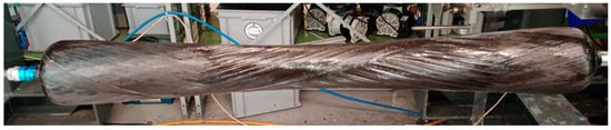
Figure 2.
Filament winding of novel CFRP sleeves.

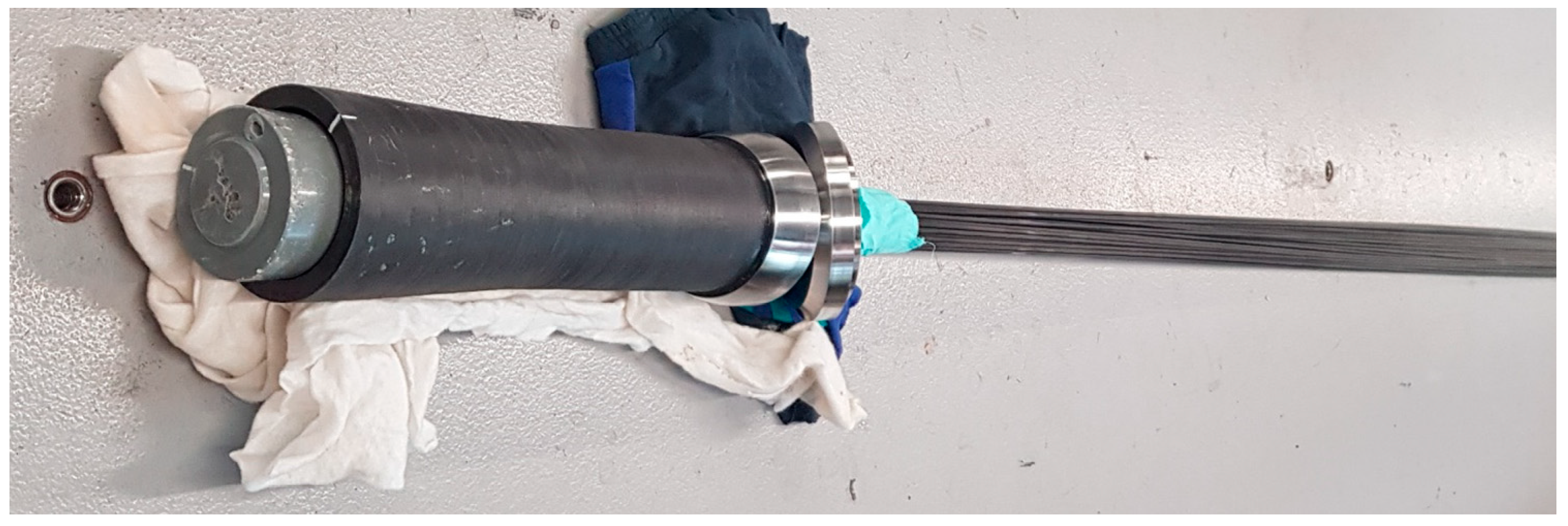
Figure 3.
Filament-wound CFRP sleeve of the end anchor for the north cable of the Ilfis Bridge. The protruding epoxy grout cone (the LTM) in which the 37 CFRP wires were cast can be seen at the left of the photograph. A stainless-steel end ring and a self-centering plate form the front abutment.
Carbo-Link AG also produced the exact same resin-cast end anchors of the two full-scale cable specimens for creep and tensile experiments that were successfully performed at Empa and that allowed us to rate the cables for the new bridge strengthening as 1.83 MN capacity cables [11]. These successfully passed validations convinced the canton of Lucerne (vif) to order two CFRP bridge cables made of the reused wires for post-tensioning the Ilfis Bridge. One of their four cable anchorages is shown in Figure 3 as an example.
4. Ilfis Bridge Strengthening with Two Cables Made of Reused CFRP Wires
Ilfis Bridge, depicted in Figure 4, was constructed in 1988 as a traditional prestressed reinforced concrete structure, measuring 44 m in length. Designed as a box girder, the bridge features steel strands for prestressing that run through the concrete webs of the torsion box. During the periodic inspection in 2021, several maintenance measures were identified. These included immediate upgrades to the bearings, such as strengthening to withstand earthquakes and flooding, as well as strengthening the bridge to comply with current standards and safety requirements.
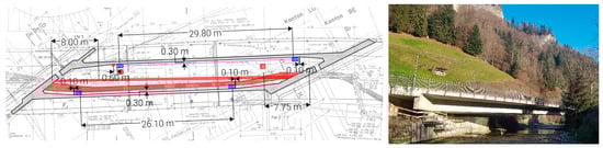
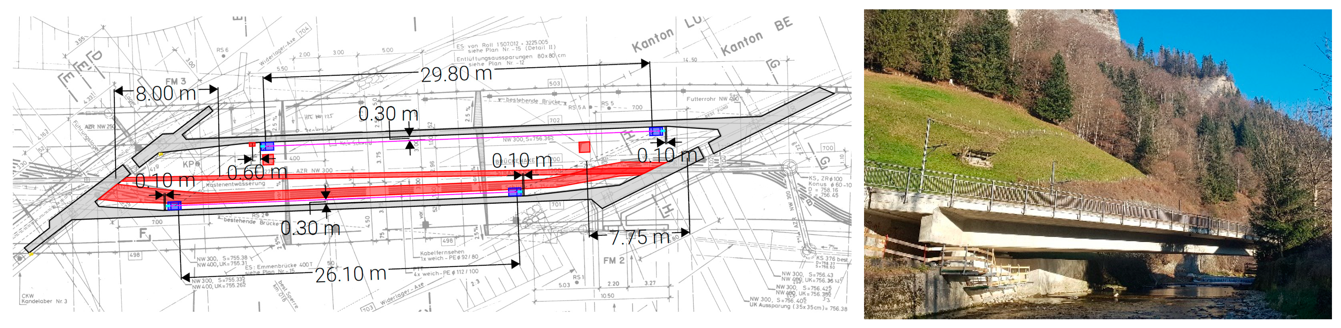
Figure 4.
Layout of the bridge (courtesy of vif Lucerne) with utility lines (red) and location of the cable sleeves with support (blue). Right picture shows the strengthened bridge over the river Ilfis in the central Swiss Alps.
The structural review of the current condition showed that with updated building material properties, updated permanent loads, and road loads in accordance with [14] and detailed resistance models, all verifications could be fulfilled with the exception of load model 3 for exceptional transports (type II in [14]).
The current prestressing force was approx. 46 MN, which should be raised by 5%, i.e., with two parallel-wire bundles (PWB) cables made of 37 CFRP wires of diameter 5 mm and a prestress of 1 MN each. The final decision by the involved parties (building authorities, general contractor, engineering companies, and Empa) was the post-strengthening with two PWB cables, as this fulfilled load model 3 of [14], leading to a utilization coefficient of 0.93 at midspan (previously 1.06). The strengthening of the bridge with two supplementary post-tensioning cables should be placed inside the narrow and congested box section (Figure 5 and Figure 6), as the belated installation of the CFRP cables is much simpler than that involving steel strands due to their low bending stiffness and very low weight of only 1.2 kg/m.
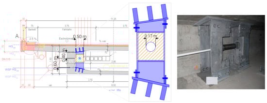
Figure 5.
Welded steel construction to support the cable sleeves and to transfer the loads via shear dowels into the bridge.
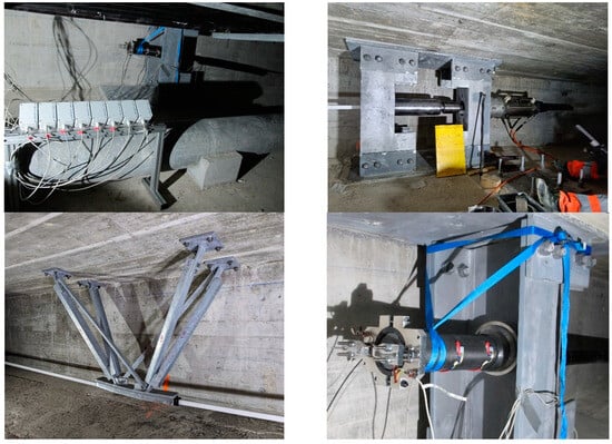
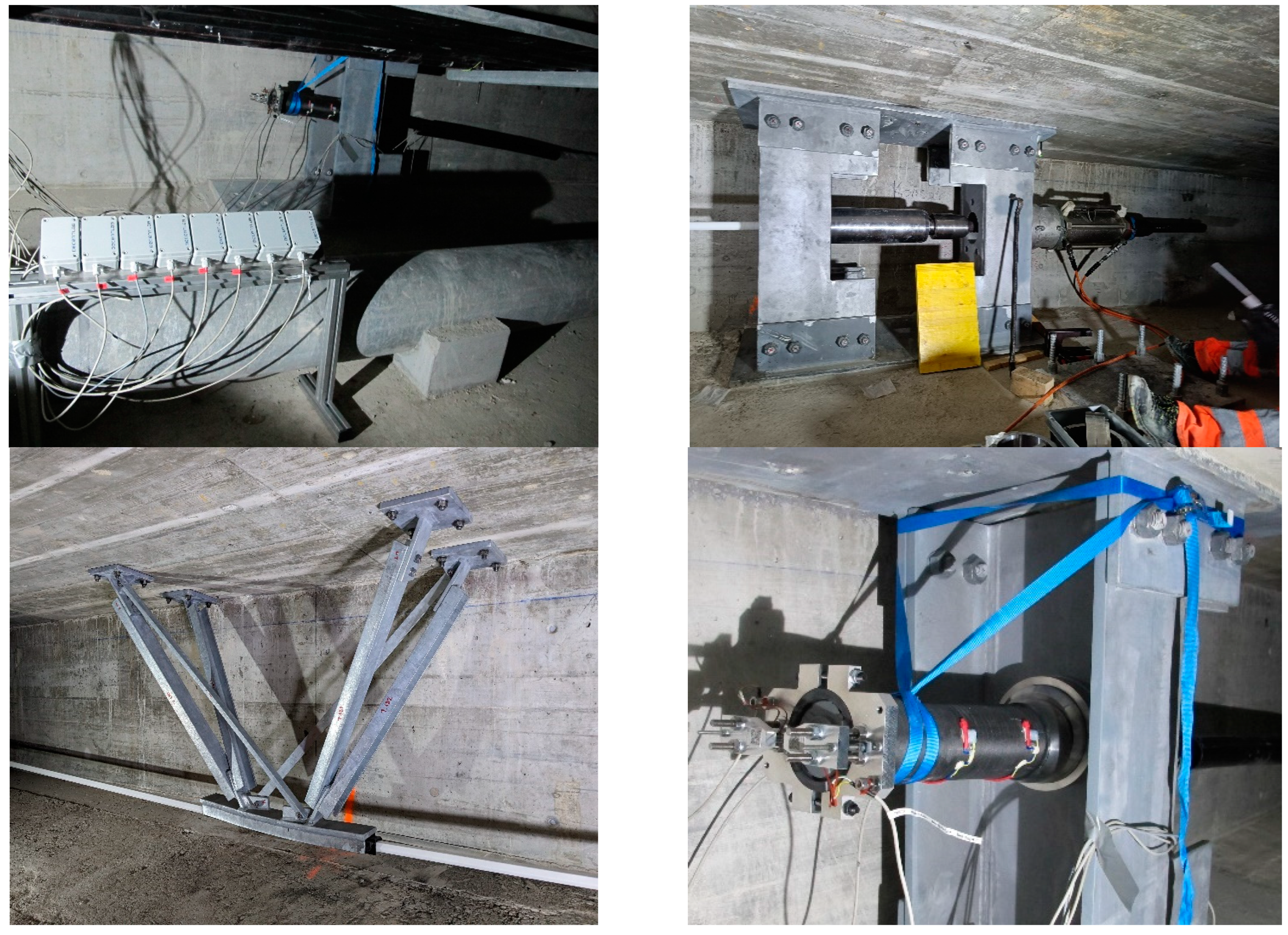
Figure 6.
Prestressing with mobile hydraulic jack (top right, jack at right end), installed cable anchor (CFRP sleeve) with 2 RSG and end-slippage sensors after prestressing in the foreground (bottom right), monitoring system for cable/anchor strains and slippage measurement (overview, top left, in the foreground 8 measurement amplifiers and data transmitters for RSG sensors are shown), and the central steel frame for deflecting the PWB cable at midspan (bottom left, cable in gray PE hose).
One of the main challenges was anchoring the cables and introducing the load into the bridge’s box section, as the available space was very restricted, partly due to the presence of utility lines and water pipes inside the box girder. Figure 5 illustrates a cross section of the bridge, highlighting the planned cable position and its connection to the concrete girder. To bear the cable loads and transfer them into the bridge structure, large welded steel brackets had to be fabricated and installed. The box-shaped structures transferred the prestress into the bridge through multiple shear dowels. These components were designed to allow the prestressing of the cables using mobile hydraulic presses and small auxiliary equipment. Figure 6 shows both the prestressing setup and the completed installation.
The installation of the CFRP cables and the prestressing was performed during one day on 23 August 2023, and the monitoring system was started to record the strains on selected tendons and on the CFRP sleeves and the draw-in of the grouted LTM cones into the sleeves. The initial results of this long-term monitoring are presented in Section 5.
5. Experimental Results and Discussion: Monitoring Prestress of CFRP Bridge Cables
Directly after the cable production at Carbo-Link AG, the two CFRP parallel-wire cables were equipped with resistive strain gauges (RSGs) on four wires, located 1 m before the passive anchor end. Additionally, one longitudinal and one transverse strain gauge were installed on the CFRP sleeves at the passive cable end (Figure 6, bottom right). The longitudinal RSG was placed 40 mm from the anchor front, and the transverse RSG was positioned 225 mm from the sleeve end. Furthermore, RSG-based displacement transducers were used to measure the draw-in of the Load Transfer Media (LTM, i.e., the epoxy grout cone shown in Figure 3) at the passive cable anchor end, utilizing cantilever beam springs with two RSGs mounted on their edges. All strain gauges were of type HBM 1-LY41-6/700 [15], configured as half bridges and being temperature-compensated.
Once the sensors were calibrated in the unloaded cable system, the cables were installed and anchored in the bridge box girder, and the prestress force was applied on 23 August 2023. Strain monitoring began at the start of the prestressing process, and data have been recorded periodically ever since. The sensor data are transmitted in real-time using LoRaWAN® wireless technology [16], which allows for encrypted radio transmissions over long distances. The data are sent to Empa through Decent Lab’s [16] data storage and visualization system. During prestressing, the monitoring rate was set to one measurement cycle every 10 min, later increasing to one cycle every 3 h for long-term monitoring.
The measurements of the wire elongations have shown stable values over the first 14 months, as illustrated in Figure 7 for the north cable. However, some variability was observed between the strains of the four wires in each post-tensioning cable. This variability can be attributed to three main factors:
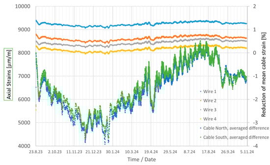
Figure 7.
Longitudinal strains of the 4 CFRP wires monitored in the north cable vs. monitoring time (bridge post-tensioning occurred on 23 August 2023). Right y-axis: average prestress reduction vs. monitoring time for both CFRP bridge cables (north and south).
Cable production, as slight variations occurred in the alignment of the individual wires during the casting of the anchor with the LTM, leading to variations in the base length (l0).
Edge distance/position of the wire within the cable (which can also be affected by cable deflection in the middle).
Measurement accuracy, which is estimated to be within ±1%, based on RSG specification [15]. In addition, slight misalignments of the RSG (estimated at ±2°) during application cannot be excluded.
Slight differences in the degree of CFRP cable prestressing were observed between north cable and south cable (5.7%). This is primarily due to the prestressing process itself. The total clamping force could not be monitored in real time using a load cell as in the laboratory (i.e., in the full-scale tensile failure tests [11]) but was calculated using the oil pressure of the mobile hydraulic prestressing jack (Figure 6, top right). The target force value could therefore not be approached with high precision.
When the cables were prestressed to the planned nominal load of 1 MN, the average CFRP stresses achieved were 1427 MPa (north cable) and 1350 MPa (south cable), which correspond to an average CFRP wire strain of 8755 μm/m and 8282 μm/m, respectively. After 14 months of monitoring, the wire elongations have decreased by an average of 1% (Figure 7, right y-axis). This is mainly due to seasonal temperature fluctuations.
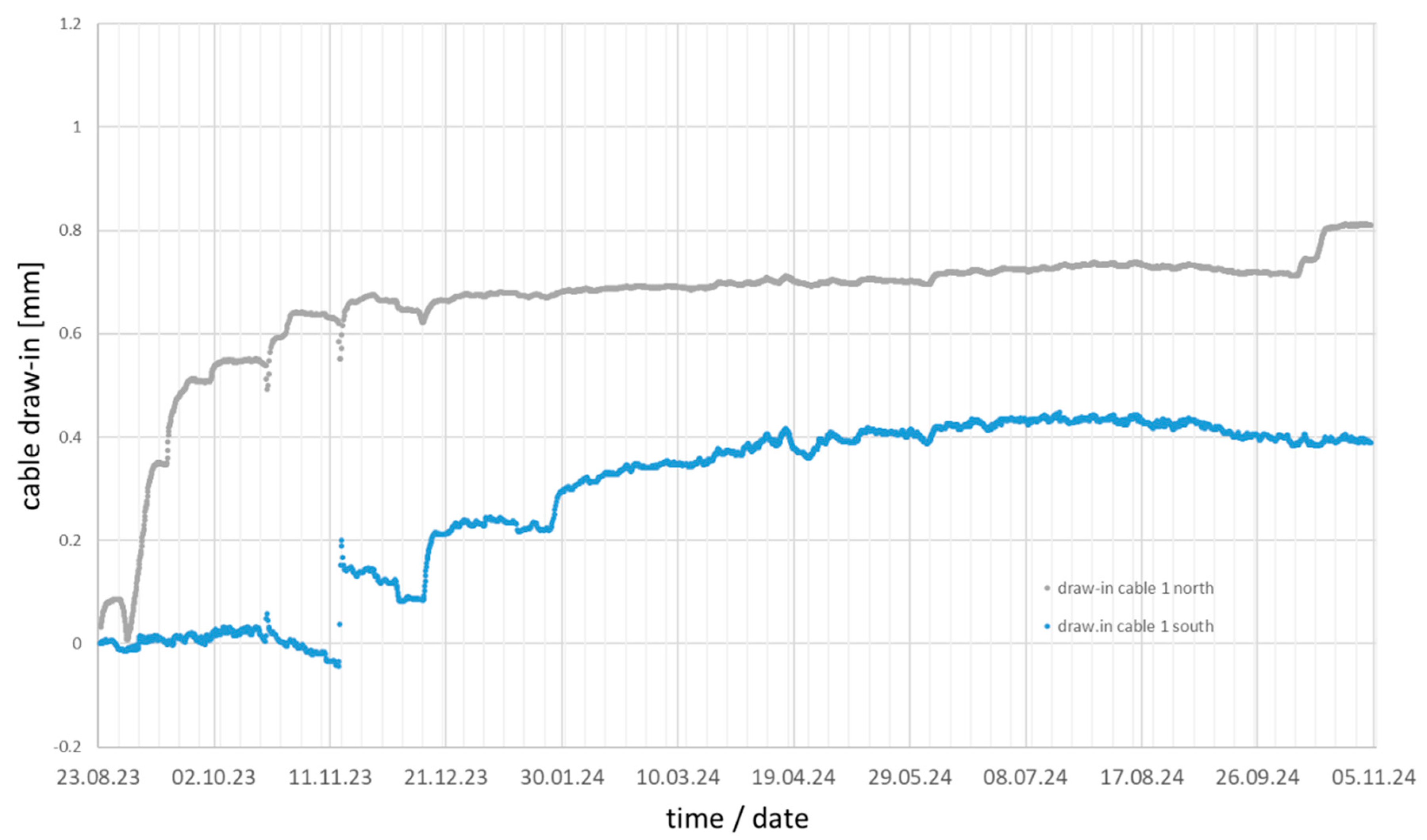
The draw-in displacements of the passive anchor’s LTM during prestressing to 1 MN were 11.2 mm on average for the north cable and 10.4 mm for the south cable, which was mainly caused by a 5.7% lower prestressing force in the south cable. These draw-ins increased by 0.8 mm for the north cable and by 0.4 mm in the case of the south cable during the first 14 monitoring months, thus indicating a negligible settling (creep) of the polymeric LTM in the CFRP sleeves (Figure 8).
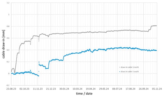
Figure 8.
Draw-in displacements in mm vs. monitoring time of both CFRP anchor’s LTM for the north cable (reference is the measurement start just after installation and prestressing).
The longitudinal and transverse (hoop) strains on the CFRP sleeves showed nearly constant values over 14 months and were at −0.21% (north cable) and −0.27% (south cable) and 0.13% (north cable) and 0.21% (south cable), respectively. The long-term measurements of strains on the CFRP sleeves and the LTM draw-ins are particularly important in obtaining information about whether an anchorage component tends to creep (viscoplastic, time-dependent deformation under permanent load). The strains and LTM shifts should eventually reach a constant value.
The decrease in wire elongation shown in Figure 7 is explained by the very limited time-dependent creep and draw-in of the LTM in the sleeve of the cables (of minor influence) and predominantly by the bridge compression due to a decrease in temperature from summer to autumn and to winter (since the old concrete hardly creeps), e.g., with a 25 °C temperature reduction between the strengthening day, 23 August 2023, and the end of January 2024, this results in approx. 250 µm/m due to thermal concrete contraction. After 14.5 months of monitoring (5 November 2024), a total decrease of approximately 85 µm/m was measured (corresponding to the −1% in Figure 7, right y-axis).
(Assumptions: Coefficient of Thermal Expansion (CTE) of concrete = approx. 10 × 10−6 1/°C and CTE of CFRP wire in the longitudinal direction = approx. 0 [1/°C]).
6. Conclusions
This paper describes the successful reuse of 25-year-old and serviced pultruded CFRP wires to assemble two post-tensioning cables which were designed to reinforce a 1988-built prestressed concrete bridge (Ilfis Bridge) in the central Swiss Alps. A novel resin-cast CFRP anchorage system was developed successfully for CFRP parallel-wire cables by the authors. Its effectiveness was initially proven in full-scale sustained tension creep tests and in quasi static tensile tests to failure (achieving a 95% utilization ratio with respect to the statistically determined 99% wire remnant strength quantile of 2648 MPa [11]). This gave the team confidence to use the novel CFRP anchor system for post-tensioning the Ilfis Bridge in the summer of 2023. Finally, the strengthening of the bridge box girder was described and the first monitoring data gathered during the initial 14.5 service months were presented and discussed. The strain gauge sensors applied to the 25-year-old CFRP wires and to the new CFRP anchor sleeves proved effective in measuring tensile, hoop, and compressive strains during post-tensioning, enabling the reliable monitoring of the prestress force and sleeve stresses. The strains in both the wires and anchor sleeves remained nearly constant, with only seasonal temperature fluctuations having a minor effect. Additionally, only a minimal draw-in of the resin load transfer media was detected. Hence, the performance of the newly developed CFRP parallel-wire cable anchorage system—based on filament-wound CFRP sleeves and a monolithic resin grout—was successfully validated. Future monitoring data shall further confirm the effectiveness and reliability of the novel CFRP cables, which were made using recovered CFRP wires, as well as their anchorages and the strain gauge-based CFRP monitoring system. This project shows one possible reuse application and the sustainability potential for 25-year-old pultruded CFRP wires which were previously prestressed to 45% of their design tensile strength for 17.5 years in a post-tensioned bridge.
The environmental and economic feasibility of reusing CFRP pultrusions in large-scale applications, such as bridge strengthening, was proven by this case study. It is important to note that reusing CFRP pultrusions/wires that are easy to be recovered out of a decommissioned bridge (as they are not adhesively bonded to the concrete, an important prerequisite) saves initial material costs, cable manufacturing costs (simpler anchorage grouting due to the much lower weight of CFRP compared to steel cables), cable installation costs in the bridge, and corrosion protection costs that are not needed for durable CFRP. Furthermore, there is no need for periodical corrosion protection renewal and the related costs are avoided, which is not the case for steel cables (as long as the installed cables are enclosed). This reduction in construction-site labor (maintenance) and manufacturing work highlights the noticeable sustainability and cost advantage of CFRP, which has also been proven by Meier et al. [17] for prestressed CFRP bridge hangers. It is emphasized that the weight, strength, and durability advantages of CFRP (due to excellent stress corrosion and fatigue resistance) over metals make CFRP the material of choice that enables safety and sustainability in other highly loaded structures like aircrafts. This is mainly attributed to the airlines’ requirements to reduce kerosene fuel (energy) consumption by lighter aircrafts, therewith also reducing CO2 emissions and the maintenance costs due to the longer design life of CFRP over aluminum and steel alloys [18]. Recently developed externally bonded nanoparticle-modified CFRP strengthening patches (EBR method) were proven effective in strengthening reinforced concrete frames and should be investigated in the future in terms of their sustainability and reuse potential after a CFRP-strengthened concrete building has reached its EOL [19].
The authors hope that this case-study will urge the scientific and industrial FRP composite community to find applications for similar CFRP pultrusions that are at the End Of their first service Life (EOL applications).
Author Contributions
Conceptualization, G.P.T., G.S. and C.A.; methodology, G.P.T. and C.A.; software, A.G. and A.W.; validation, G.P.T., G.S. and C.A.; formal analysis, G.P.T., G.S. and C.A.; investigation, G.P.T., A.G. and C.A.; resources, G.P.T. and G.S.; data curation, G.P.T., A.G. and C.A.; writing—original draft preparation, G.P.T., A.G. and C.A.; writing—review and editing, G.P.T. and C.A.; supervision, G.P.T., A.G. and C.A.; project administration, G.P.T. and G.S.; funding acquisition, G.P.T. and G.S. All authors have read and agreed to the published version of the manuscript.
Funding
This research was funded by Innosuisse, grant number 48164.1 IP-ENG, and the APC was funded by Lib4RI of the ETH domain.
Data Availability Statement
The original contributions presented in this study are included in the article. Further inquiries can be directed to the corresponding author.
Acknowledgments
We would like to express our gratitude to V. Bemetz and A. Guelzow (Carbo-Link AG) for their valuable contribution to the development of the anchorage and the production of the prototypes. Additionally, we extend our thanks to Valentin Ott and Alex Stutz (Empa MSE) for their work on cable testing and on strain monitoring. We acknowledge the valuable inputs and discussions with Andreas Rösli (vif, Canton of Lucerne), B. Leu, T. Glauser (Deuring+Öhninger AG), M. Kaufmann, and S. Jedelhauser (Basler & Hofmann AG).
Conflicts of Interest
Authors Andre Guerotto and Andreas Winistörfer are employed by the company Carbo-Link AG. The remaining authors declare that the research was conducted in the absence of any commercial or financial relationships that could be construed as a potential conflict of interest. The authors declare that this study received funding from Innosuisse. The funder was not involved in the study design, collection, analysis, interpretation of data, the writing of this article or the decision to submit it for publication.
Nomenclature
| CFRP | Carbon Fiber Reinforced Polymer (here, with epoxy polymer matrix and unidirectional fiber arrangement, produced by industrial pultrusion) |
| EBR | Externally Bonded Reinforcement |
| EOL | End Of Life |
| FRP | Fiber Reinforced Polymer (composite of fibers reinforcing a polymer matrix) |
| LTM | Load Transfer Media (resin grout material of resin cast anchors) |
| NDT | Non-Destructive Testing |
| PWB | Parallel-Wire Bundle bridge cable |
| RSG | Resistance Strain Gauges (also called foil gauges to measure strain) |
| vif | Verkehr und Infrastuktur, building authority of the Swiss canton of Lucerne (bridge owner) |
References
- Terrasi, G.P. Prefabricated Thin-walled Structural Elements Made from High Performance Concrete Prestressed with CFRP Wires. J. Mater. Sci. Res. 2013, 2, 1–10. [Google Scholar] [CrossRef]
- Meier, U.; Brönnimann, R.; Anderegg, P.; Terrasi, G.P. 20 years of experience with structural health monitoring of objects with CFRP components, in “Nondestructive testing of materials and structures”. In Rilem Bookseries; Büyüköztürk, O., Ed.; Springer: Dordrecht, The Netherlands, 2013; Volume 6, pp. 959–976. [Google Scholar]
- Fib (International Federation for Structural Concrete). Externally Applied FRP Reinforcement for Concrete Structures; Bulletin 90; Fib: Lausanne, Switzerland, 2019. [Google Scholar]
- Fib (International Federation for Structural Concrete). Fib Model Code for Concrete Structures 2010; Fib: Lausanne, Switzerland, 2013. [Google Scholar]
- Boloux, A.; Biby, L.A.; Ott, V.; Terrasi, G.P. The Performance of Prestressed Carbon Fibre Reinforced Polymer (CFRP) Bridge Tendons after 18 Years in Service. In Proceedings of the ACI Spring 2024 Convention: FRPRCS 16 Conference, New Orelans, LA, USA, 24–28 March 2024. paper #B9836. [Google Scholar]
- American Concrete Institute. American Concrete Institute 2015, Guide for the Design and Construction of Structural Concrete Reinforced with Fiber-Reinforced Polymer (FRP) Bars, 1st ed.; in ACI report, no. 440.1R–15; American Concrete Institute: Farmington Hills, MI, USA, 2015. [Google Scholar]
- Yamaguchi, T.; Kato, Y.; Nishimura, T.; Uomoto, T. Creep rupture of FRP rods made of aramid, carbon and glass fibers. In Proceedings of the Third International Symposium on Non-Metallic (FRP) Reinforcement for Concrete Structures (FRPRCS-3), Sapporo, Japan, 14–16 October 1997; Japan Concrete Institute: Tokyo, Japan, 1997; pp. 179–186. [Google Scholar]
- Yang, D.; Zhang, J.; Song, S.; Zhou, F.; Wang, C. Experimental Investigation on the Creep Property of Carbon Fiber Reinforced Polymer Tendons under High Stress Levels. Materials 2018, 11, 2273. [Google Scholar] [CrossRef] [PubMed]
- Balázs, G.; Borosnyói, A. Long-term behavior of FRP. In Composites in Construction: A Reality; ASCE (American Society of Civil Engineers): Reston, VA, USA, 2001; pp. 84–91. [Google Scholar] [CrossRef]
- Meier, U.; Meier, H.; Kim, P. Anchorage Device for High-Performance Fiber Composite. Cables. Patent WO1995029308A1, 2 November 1995. [Google Scholar]
- Terrasi, G.P.; Affolter, C.; Stutz, A.; Schwegler, G.; Guerotto, A.; Winistoerfer, A. 2024. Re-use of 25 years old CFRP pultrusions in novel post-tensioning cables for bridge strengthening. Procedia Struct. Integr. 2024, 64, 1347–1359. [Google Scholar] [CrossRef]
- IMS60 Teijin Carbon Fibres 2024. Available online: https://www.teijincarbon.com/fileadmin/user_upload/Datenbl%C3%A4tter/Filament_Yarn/Product_Data_Sheet_TSG01en__EU_Filament_.pdf (accessed on 22 November 2024).
- Huntsman Basel Switzerland. Araldite LY 564/Aradur. 2954. Hot Curing Epoxy System. 2024. Available online: https://files.ekmcdn.com/mouldlife/resources/other/araldite-ly564-aradur-2954-eur-e-1-.pdf (accessed on 22 November 2024).
- SIA 269; Grundlagen der Erhaltung von Tragwerken (in German, Design Fundametals for the Preservation of Existing Structures). Swiss Engineers and Architects Society (SIA): Zurich, Switzerland, 2011.
- HBK. Hottinger Brühel und Kjaer. 2024. Available online: https://www.hbm.com/de/4561/ly-lineare-dehnungsmessstreifen-mit-1-messgitter (accessed on 18 March 2024).
- Decent Lab. LoRaWAN Technology. 2024. Available online: https://www.decentlab.com/lorawan (accessed on 18 March 2024).
- Meier, U.O.; Winistörfer, A.U.; Haspel, L. World’s First Large Bridge Fully Relying on Carbon Fiber Reinforced Polymer Hangers. SAMPE J. 2021, 57, 22–30. [Google Scholar]
- Zhang, J.; Lin, G.; Vaidya, U.; Wang, H. Past, present and future prospective of global carbon fibre composite developments and applications. Compos. Part B 2023, 250, 110463. [Google Scholar] [CrossRef]
- Cheng, W.; Lin, B.; Li, D.; Zhang, J.; Cui, S. Progressive collapse performance of shear strengthened RC frames by nano CFRP. Nanotechnol. Rev. 2022, 11, 811–823. [Google Scholar] [CrossRef]


Disclaimer/Publisher’s Note: The statements, opinions and data contained in all publications are solely those of the individual author(s) and contributor(s) and not of MDPI and/or the editor(s). MDPI and/or the editor(s) disclaim responsibility for any injury to people or property resulting from any ideas, methods, instructions or products referred to in the content. |
© 2024 by the authors. Licensee MDPI, Basel, Switzerland. This article is an open access article distributed under the terms and conditions of the Creative Commons Attribution (CC BY) license (https://creativecommons.org/licenses/by/4.0/).