Research on the Effect of Geometric Parameters on the Stress Concentration Factor of Multi-Planar KK-Joints and Carbon Fiber-Reinforced Polymer Wrapping Rehabilitation with Numerical Simulation

Abstract
1. Introduction
2. Verification of the FE Model
2.1. Establishment of the FE Model
2.1.1. Component Creation and Material Properties
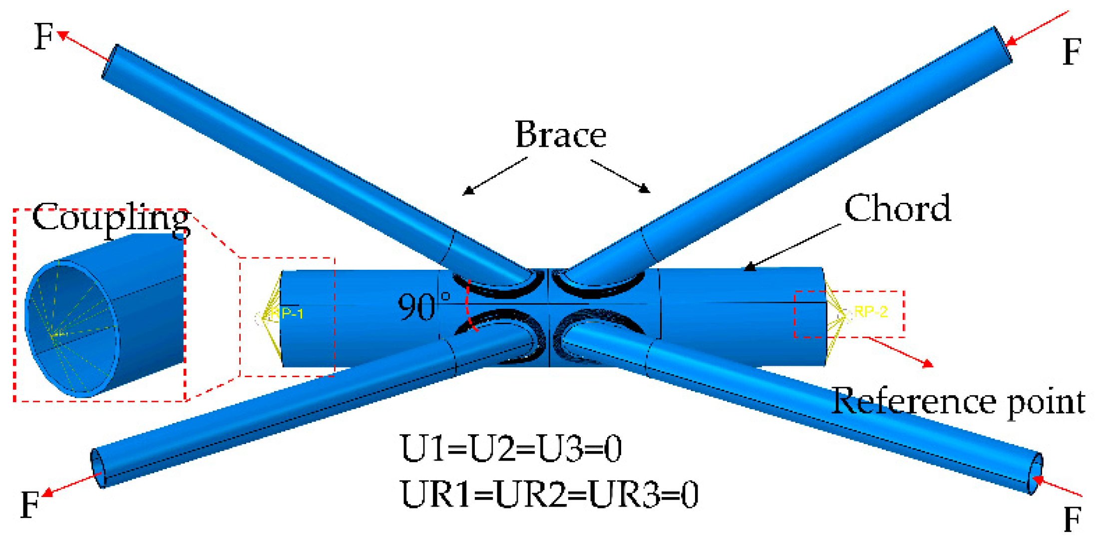
2.1.2. Mesh, Load, and Boundary Conditions
2.1.3. Interaction Setting and CFRP Direction
2.2. Analysis and Extraction of SCFs
2.3. Results Between Tong’s Test and Verification Models
3. Design Scheme for the Numerical Analysis Model
4. Effect of Geometrical Parameters on SCFs
4.1. Details of Parametric Investigation
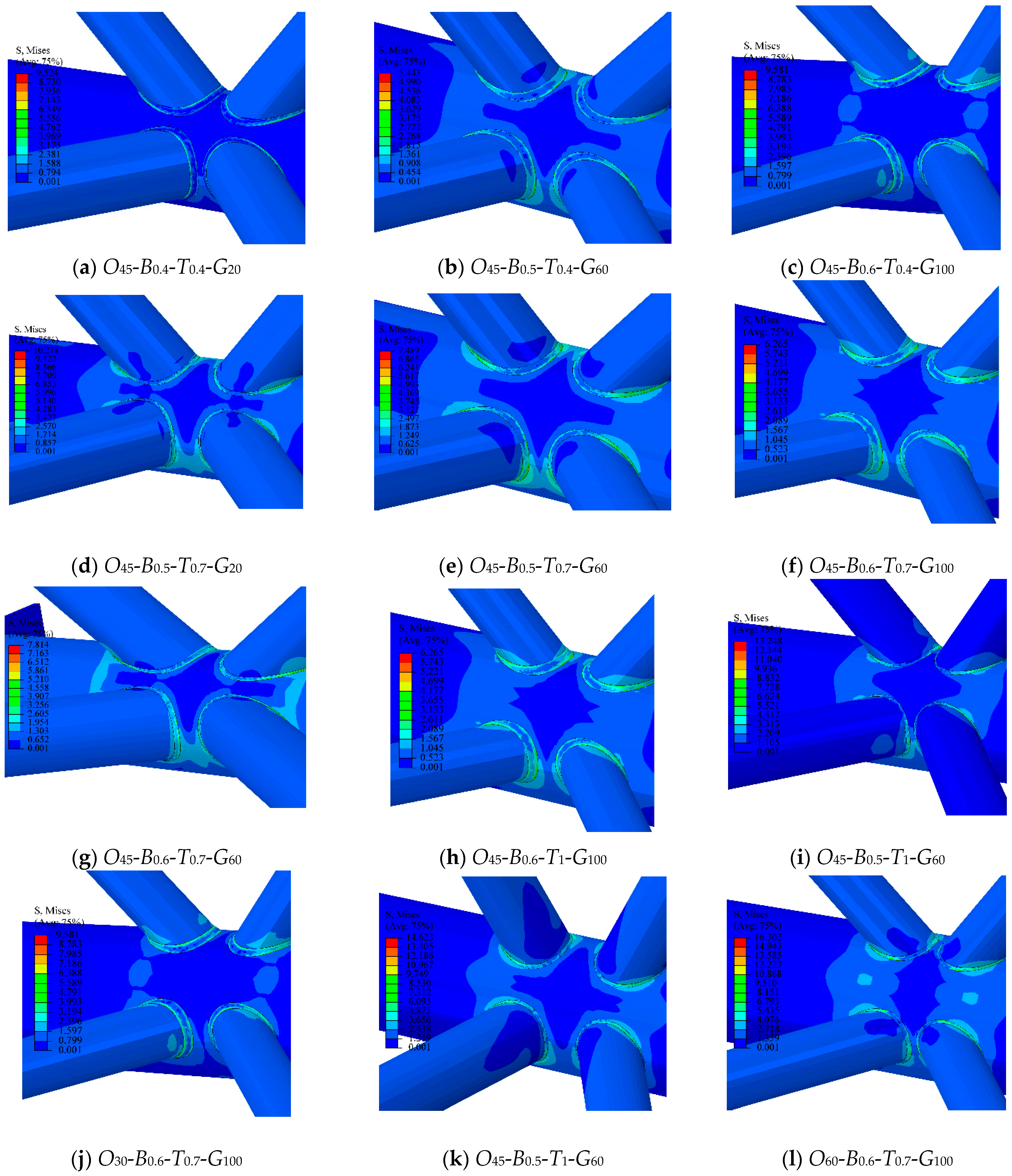
4.2. The Effect of Different Geometric Parameters on Stress Contours
4.3. Effects of Geometrical Parameters on the SCF
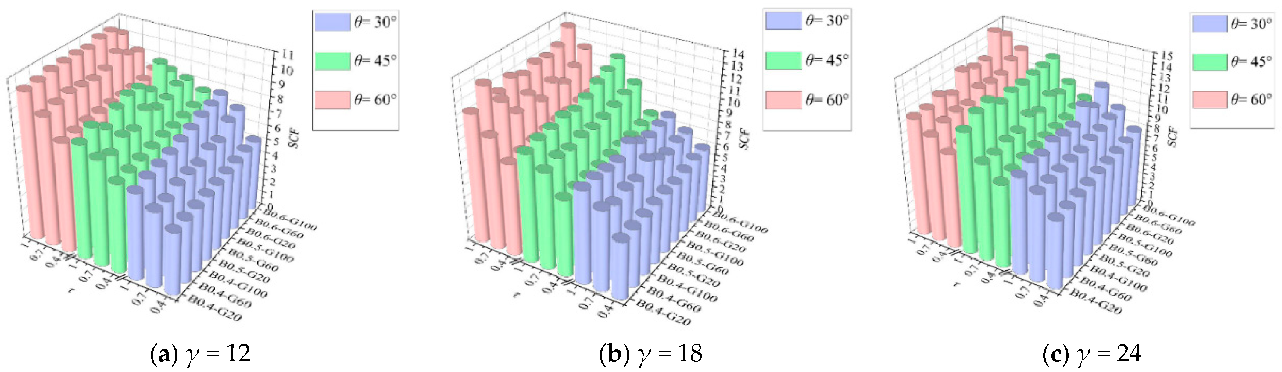
4.3.1. Results of β
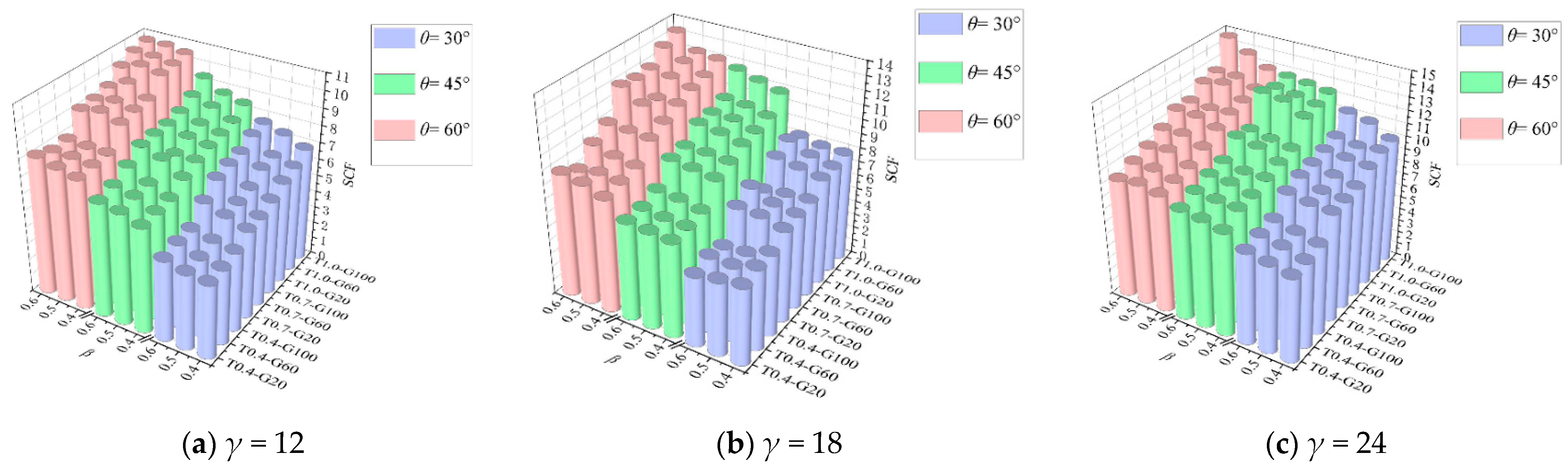
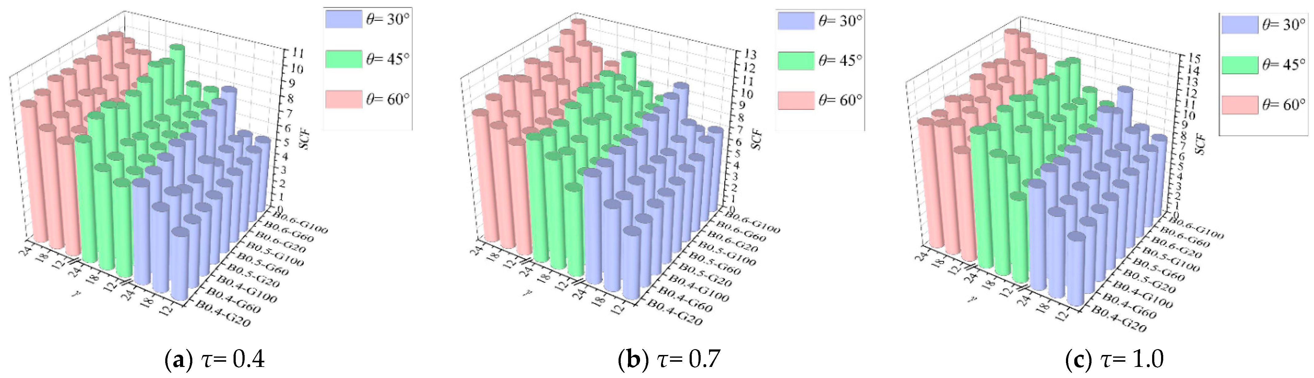
4.3.2. Results of τ
4.3.3. Results of γ
4.3.4. Results of θ
4.3.5. Results of g
5. Analysis of the SCF of Cracked KK-Joints Strengthened with FRP
5.1. The Establishment of Reinforced Models
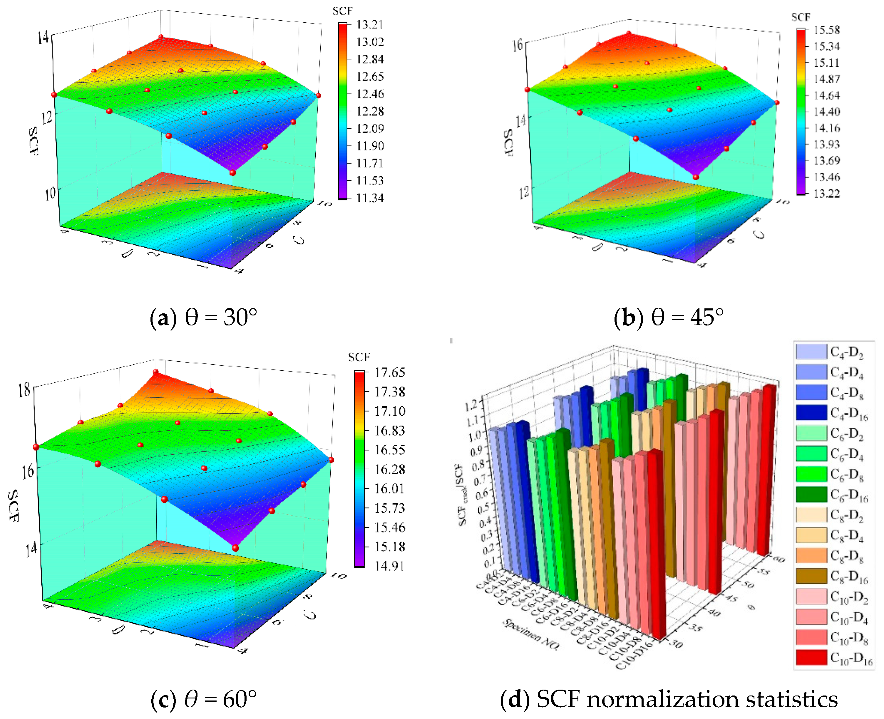
5.2. Effect of Crack Depth and Length on the SCF
5.3. Results of Cracked Joints Strengthened with CFRP
5.3.1. Model Scheme of FRP-Reinforced Joints with Initial Cracks
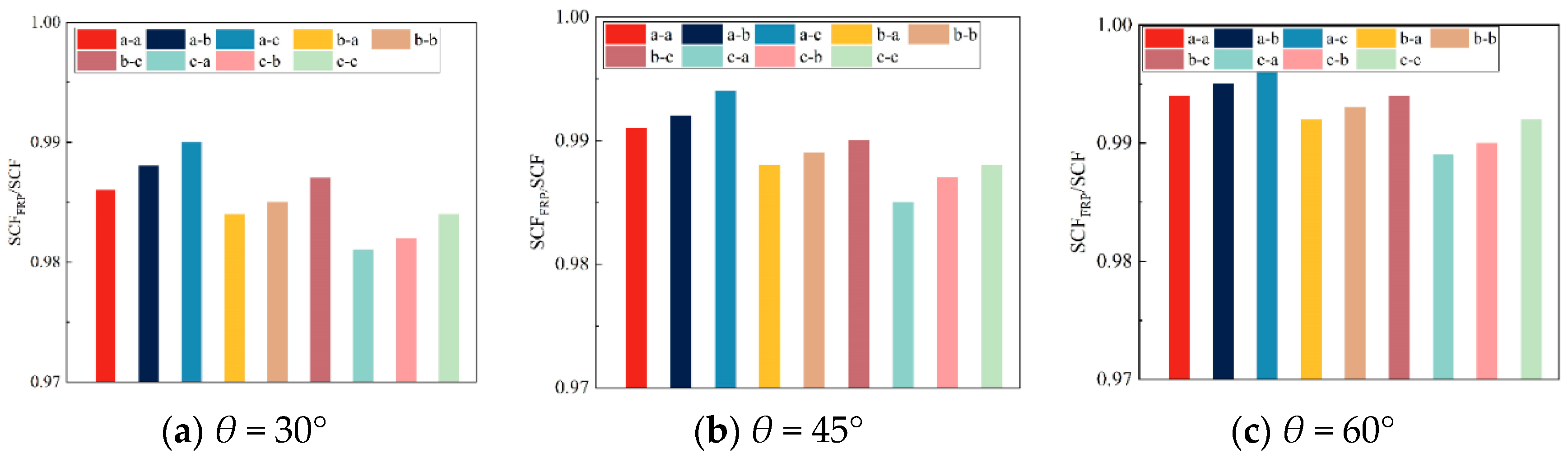
5.3.2. Reinforced with One-Layer CFRP
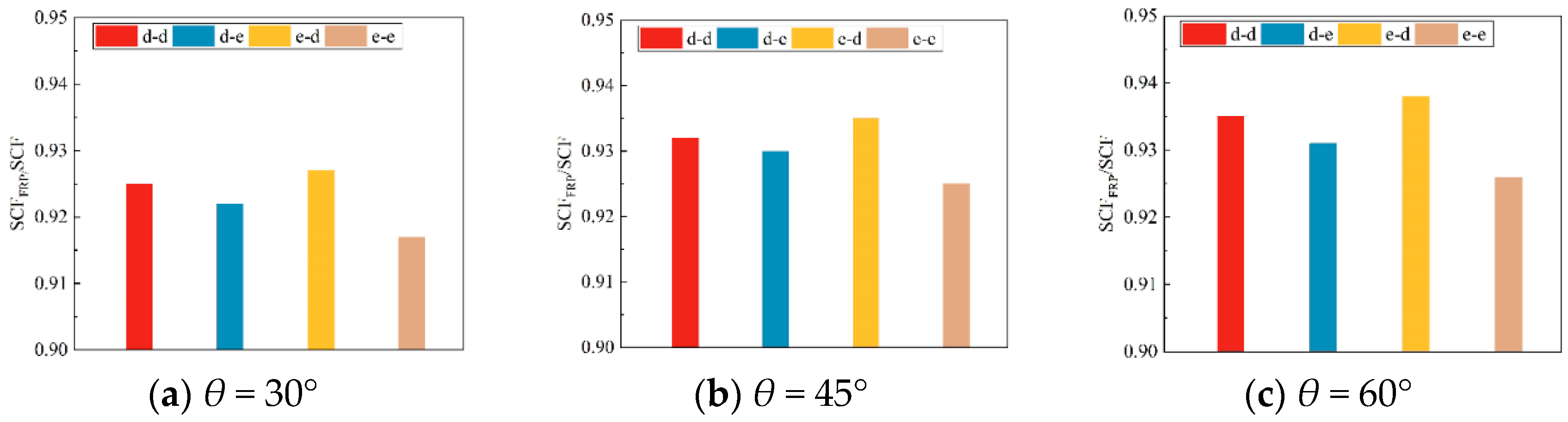
5.3.3. Reinforced with Two-Layer CFRP
5.3.4. Reinforced with Multi-Layer CFRP
5.4. Analysis of CFRP-Strengthened KK-Joints with Cracks
6. Fitting Relationships for the SCF of KK-Joints with Different Parameters
7. Conclusions
Author Contributions
Funding
Data Availability Statement
Conflicts of Interest
Nomenclature
| θ | brace inclination angle | γ | ratio of outer diameter to wall thickness of chord |
| τ | thickness ratio of brace to chord | T | the thickness of chord |
| β | ratio of radius of brace to chord | α | brace-to-chord thickness ratio |
| ζ | relative gap | d0 | the chord diameter |
| t0 | the chord diameter wall thickness | d1 | the brace diameter |
| t1 | the brace diameter wall thickness | dc | damage factor during the CFRP expansion process |
| C2 | equivalent plastic damage strain (pure shear test) | C1 | equivalent plastic damage strain (uniaxial tensile test) |
| XT | longitudinal tensile strength of fibers | XC | longitudinal compressive strength of fibers |
| YT | longitudinal tensile strength of matrix | YC | longitudinal compressive strength of the matrix |
| S12 | longitudinal shear strength of fibers | Gc | failure energy |
| δeq0 | initial equivalent displacement | δeqf | failure displacement |
| δeq | equivalent displacement during the damage process | dft | longitudinal tensile damage of fibers |
| dfc | longitudinal compressive damage of fibers | dmt | longitudinal tensile damage of the matrix |
| dmc | longitudinal compressive damage of the matrix | σn | nominal stress of the axially loaded brace |
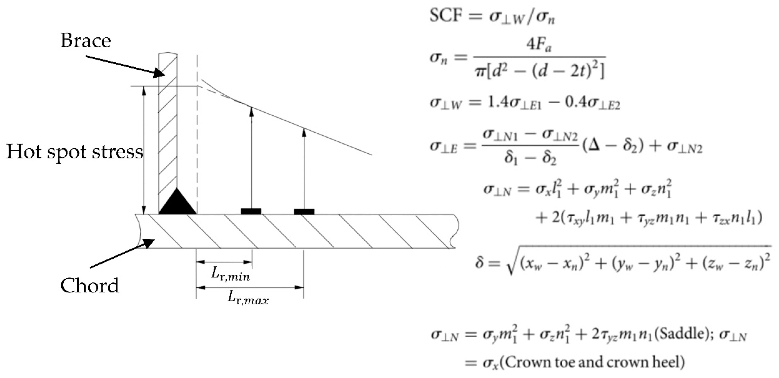
| σW | extrapolated stress at the weld toe position that is perpendicular to the weld toe | Fa | the applied axial force |
| σE1 | stresses at the first extrapolation points along the direction perpendicular to the weld toe | σE2 | stresses at second extrapolation points along the direction perpendicular to the weld toe |
| σni | the nodal stress at the immediate vicinity of the extrapolation points along the direction perpendicular to the weld toe | δi | the distance between the weld toe and the considered node inside the extrapolation region |
| Δ | 0.4T and 1.4T for the first and second extrapolation points | σa | the stress tensor |
| X1 | direction perpendicular to the weld toe | x, y, z | axes of the global coordinate system |
References
- Wardenier, J.; Packer, J.A.; Zhao, X.L.; Vegte, G. Hollow Sections in Structural Applications; Comité International Pour le Développement et l’Etude de la Construction Tubulaire: Geneva, Switzerland, 2010; ISBN 978-90-72830-86-9. [Google Scholar]
- Cooper, G.W. New Study Shows Why Fixed Platforms Fail During Storms. Oil Gas 1967, 65, 42. [Google Scholar]
- Woghiren, C.O.; Brennan, F.P. Weld toe stress concentrations in multi-planar stiffened tubular KK joints. Int. J. Fatigue 2009, 31, 164–172. [Google Scholar] [CrossRef]
- Pantelides, C.P.; Nadauld, J.; Cercone, L. Repair of Cracked Aluminum Overhead Sign Structures with Glass Fiber Reinforced Polymer Composites. J. Compos. Constr. 2015, 7, 118–126. [Google Scholar] [CrossRef]
- Fam, A.; Witt, S.; Rizkalla, S. Repair of damaged aluminum truss joints of highway overhead sign structures using FRP. Constr. Build. Mater. 2006, 20, 948–956. [Google Scholar] [CrossRef]
- Nazari, A.; Guan, Z.; Daniel, W.J.T.; Gurgenci, H. Parametric Study of Hot Spot Stresses around Tubular Joints with Doubler Plates. Pract. Period. Struct. Des. Constr. 2007, 12, 38–47. [Google Scholar] [CrossRef]
- Zhu, L.; Han, S.; Song, Q.M.; Ma, L.M.; Wei, Y.; Li, S.W. Experimental study of the axial compressive strength of CHS T-joints reinforced with external stiffening rings. Thin-Walled Struct. 2016, 98, 245–251. [Google Scholar] [CrossRef]
- Usman, M.; Yaqub, M.; Auzair, M.; Khaliq, M.; Noman, M.; Afaq, A. Restorability of strength and stiffness of fire damaged concrete using various composite confinement techniques. Constr. Build. Mater. 2021, 272, 121984. [Google Scholar] [CrossRef]
- Husnain, A.; Qazi, I.A.; Khaliq, W.; Arshad, M. Immobilization in cement mortar of chromium removed from water using titania nanoparticles. J. Environ. Manag. 2016, 172, 10–17. [Google Scholar] [CrossRef]
- Mohamed, H.S.; Yang, X.S.; Liao, F.Y.; Fu, T. SCF determination of the CFRP- fortified T/Y-joints exposed to IPB or OPB moment via ZPSS approach. Structures 2024, 61, 105997. [Google Scholar] [CrossRef]
- Xu, Y.; Yu, Q.; Xu, G. Numerical analysis of SCF of Tubular T-joints strengthened with prestressed CFRP. Procedia Struct. Integr. 2024, 64, 1865–1872. [Google Scholar] [CrossRef]
- Iqbal, M.; Karuppanan, S.; Perumal, V.; Ovinis, M.; Khan, A. Stress Concentration Factors in CFRP-Reinforced KT-Joints under Multiplanar Bending Loads: Experimental and Numerical Investigation. Results Eng. 2024, 25, 103745. [Google Scholar] [CrossRef]
- IIW-XV-E. Recommended Fatigue Design Procedure for Welded Hollow Section Joints; IIW Docs, XV-1035–99/XIII-1804–99; International Institute of Welding: Yutz, France, 1999. [Google Scholar]
- Shao, Y. Geometrical effect on the stress distribution along weld toe for tubular T- and K-joints under axial loading. J. Constr. Steel Res. 2007, 63, 1351–1360. [Google Scholar] [CrossRef]
- Cao, Y.G.; Meng, Z.B.; Zhang, S.H.; Tian, H.Q. FEM study on the stress concentration factors of K-joints with welding residual stress. Appl. Ocean Res. 2013, 43, 195–205. [Google Scholar] [CrossRef]
- Chen, K.M.; Huang, H.H.; Wu, Q.X.; Nakamura, S.; Chen, B.C. Experimental and finite element analysis research on the fatigue performance of CHS K-joints. Eng. Struct. 2019, 197, 14. [Google Scholar] [CrossRef]
- Ahmadi, H.; Zavvar, E. The effect of multi-planarity on the SCFs in offshore tubular KT-joints subjected to in-plane and out-of-plane bending loads. Thin-Walled Struct. 2016, 106, 148–165. [Google Scholar] [CrossRef]
- Ahmadi, H.; Lotfollahi-Yaghin, M.A.; Yongbo, S. Chord-side SCF distribution of central brace in internally ring-stiffened tubular KT-joints: A geometrically parametric study. Thin-Walled Struct. 2013, 70, 93–105. [Google Scholar] [CrossRef]
- American Petroleum Institute (API). Recommended Practice for Planning, Designing and Constructing Fixed Offshore Platforms: Working Stress Design: RP 2A-WSD, 21st ed.; Errata and Supplement 3; API: Washington, DC, USA, 2007. [Google Scholar]
- Ahmed, A.K.; Ahmed, M.E.; Abdel-salaam, A.M.; Eslam, N.E.-G.; Aboul, H.S. Parametric study of Unstiffened multi-planar tubular KK-Joints. Results Eng. 2022, 14, 100400. [Google Scholar] [CrossRef]
- Ahmadi, H.; Lotfollahi-Yaghin, M.A.; Aminfar, M.H. Effect of stress concentration factors on the structural integrity assessment of multi-planar offshore tubular DKT-joints based on the fracture mechanics fatigue reliability approach. Ocean Eng. 2011, 38, 1883–1893. [Google Scholar] [CrossRef]
- UK Health and Safety Executive. OTH 354: Stress Concentration Factors for Simple Tubular Joints—Assessment of Existing and Development of New Parametric Formulae; Lloyd’s Register of Shipping: London, UK, 1997.
- Bao, S.; Wang, W.; Zhou, J.; Li, X. Study on hot spot stress distribution of three-planar tubular Y-joints subjected to in-plane bending moment. Mar. Struct. 2023, 87, 22. [Google Scholar] [CrossRef]
- Lotfollahi-Yaghin, M.A.; Ahmadi, H. Geometric stress distribution along the weld toe of the outer brace in two-planar tubular DKT-joints: Parametric study and deriving the SCF design equations. Mar. Struct. 2011, 24, 239–260. [Google Scholar] [CrossRef]
- Lee, M.M.K.; Wilmshurst, S.R. Numerical modelling of CHS joints with multiplanar double-K configuration. J. Constr. Steel Res. 1995, 32, 281–301. [Google Scholar] [CrossRef]
- Lee, M.M.K. Strength, stress and fracture analyses of offshore tubular joints using finite elements. J. Constr. Steel Res. 1999, 51, 265–286. [Google Scholar] [CrossRef]
- Shao, Y. Fatigue Behaviour of Uniplanar CHS Gap K-Joints Under Axial and In-Plane Bending Loads. Ph.D. Thesis, Nanyang Technological University, Singapore, 2004. [Google Scholar]
- Cao, J.; Yang, G.; Packer, J.A. FE mesh generation for circular tubular joints with or without cracks. In Proceedings of the Seventh International Offshore and Polar Engineering Conference, Honolulu, HI, USA, 25 May 1997. [Google Scholar]
- Lesani, M.; Bahaari, M.R.; Shokrieh, M.M. Numerical investigation of FRP-strengthened tubular T-joints under axial compressive loads. Compos. Struct. 2013, 100, 71–78. [Google Scholar] [CrossRef]
- Lesani, M.; Bahaari, M.R.; Shokrieh, M.M. Experimental investigation of FRP-strengthened tubular T-joints under axial compressive loads. Constr. Build. Mater. 2014, 53, 243–252. [Google Scholar] [CrossRef]
- AHosseini, S.; Bahaari, M.R.; Lesani, M. SCF distribution in FRP-strengthened tubular T-joints under brace axial loading. Sci. Iran. 2020, 27, 1113–1129. [Google Scholar] [CrossRef]
- Hosseini, A.S.; Bahaari, M.R.; Lesani, M. Parametric Study of FRP Strengthening on Stress Concentration Factors in an Offshore Tubular T-Joint Subjected to In-Plane and Out-of-Plane Bending Moments. Int. J. Steel Struct. 2019, 19, 1755–1766. [Google Scholar] [CrossRef]
- Hosseini, A.S.; Bahaari, M.R.; Lesani, M. Stress concentration factors in FRP-strengthened offshore steel tubular T-joints under various brace loadings. Structures 2019, 20, 779–793. [Google Scholar] [CrossRef]
- Fu, Y.G.; Tong, L.W.; He, L.; Zhao, X.L. Experimental and numerical investigation on behavior of CFRP-strengthened circular hollow section gap K-joints. Thin-Walled Struct. 2016, 102, 80–97. [Google Scholar] [CrossRef]
- Tong, L.W.; Xu, G.W.; Zhao, X.L.; Zhou, H.M.; Xu, F. Experimental and theoretical studies on reducing hot spot stress on CHS gap K-joints with CFRP strengthening. Eng. Struct. 2019, 201, 17. [Google Scholar] [CrossRef]
- Iqbal, M.; Karuppanan, S.; Perumal, V.; Ovinis, M.; Iqbal, M. A systematic review of stress concentration factors (SCFs) in composite reinforced circular hollow section (CHS) joints. Compos. Part C Open Access 2024, 15, 100515. [Google Scholar] [CrossRef]
- GB/T700-2006; Chinese Standard: Code for Carbon Structural Steels. China Standards Press: Beijing, China, 2006. (In Chinese)
- Bao, Y.; Wierzbicki, T. On fracture locus in the equivalent strain and stress triaxiality space. Int. J. Mech. Sci. 2004, 46, 81–98. [Google Scholar] [CrossRef]
- Zhou, T.H.; Li, W.C.; Guan, Y.; Bai, L. Damage analysis of steel frames under cyclic load based on stress triaxiality. Eng. Mech. 2014, 31, 146–155. (In Chinese) [Google Scholar] [CrossRef]
- Vercher, J.; Gil, E.; Mas, Á.; Lerma, C.; Torner, M.E. Flexural Strengthening of Damaged T-Joists with Severe Corrosion Using CFRP Sheets. Adv. Mater. Sci. Eng. 2017, 2017, 6030357. [Google Scholar] [CrossRef]
- Lie, S.T.; Lee, C.K.; Chiew, S.P.; Shao, Y.B. Mesh modelling and analysis of cracked uni-planar tubular K-joints. J. Constr. Steel Res. 2005, 61, 235–264. [Google Scholar] [CrossRef]
- Bao, S.L.; Wang, W.H.; Zhou, J.K.; Qi, S.W.J.; Li, X. Experimental study of hot spot stress for three-planar tubular Y-joint: I. Basic loads. Thin-Walled Struct. 2022, 177, 16. [Google Scholar] [CrossRef]
- Gao, H.; Chen, J.; Huang, Y. Parametric research on stress concentration coefficient of KK joints. Ship Ocean Eng. 2016, 45, 114–117. (In Chinese) [Google Scholar] [CrossRef]


| Specimen No. | Nominal Geometric Parameters | Number of CFRP Layers | |||||||
|---|---|---|---|---|---|---|---|---|---|
| Unstrengthened | Strengthened | Chord d0 × t0 (mm) | Brace d1 × t1 (mm) | θ | 2γ | τ | β | Chord CFRP (ncf0) 1 | Connecting CFRP (ncf1) |
| K1-13 | CK1-13 | 219 × 8 | 127 × 6 | 45° | 27.4 | 0.75 | 0.58 | 1 | 3 |
| Test [37] Result | Chord Tensile Side | Compressive Side | Brace Tensile Side | Compressive Side | ||||||||
| C0 | C90 | C180 | C0 | C90 | C180 | C0 | C90 | C180 | C0 | C90 | C180 | |
| K1-13 | 0.37 | 2.7 | 3.1 | 1.32 | 2.44 | 4.13 | 1.59 | 1.38 | 1.91 | 1.37 | 1.54 | 2.80 |
| CK1-13 | 0.42 | 2.31 | 2.52 | 1.29 | 2.00 | 3.07 | 1.51 | 1.24 | 1.63 | 1.32 | 1.36 | 2.19 |
| Verification Models | Chord Tensile Side | Compressive Side | Brace Tensile Side | Compressive Side | ||||||||
| B0 | B90 | B180 | B0 | B90 | B180 | B0 | B90 | B180 | B0 | B90 | B180 | |
| K1-13 | 0.42 | 2.6 | 3.3 | 1.3 | 2.44 | 3.3 | 1.57 | 1.37 | 2.32 | 1.37 | 1.56 | 2.15 |
| CK1-13 | 0.40 | 2.28 | 2.0 | 1.20 | 2.04 | 2.82 | 1.58 | 1.22 | 1.75 | 1.52 | 1.43 | 1.88 |
| Groups | Specimen NO. | Parameter | Range 1 | Values | R = 406 mm L = 2460 mm l = 2200 mm |
| R12 R18 R24 | O30/45/60-B0.4/0.5/0.6-T0.4/0.7/1-Gi 2 | β | 0.2–0.95 | 0.4, 0.5, 0.6 | |
| τ | 0.2–1.0 | 0.4, 0.7, 1.0 | |||
| θ | 30–90° | 30°, 45°, 60° | |||
| γ | 7.5–32 | 12, 18, 24 |
| Groups | Specimen NO. | One-Layer-Reinforced | Two-Layer-Reinforced | ||||
|---|---|---|---|---|---|---|---|
| Specimen NO. | Direction 1 | Specimen NO. | Direction | ||||
| O30,crack O45,crack O60,crack | C4/6/8/10-D16 | FRPa/b/c-a FRPa/b/c-b FRPa/b/c-c | Chord | Brace | FRPd-d FRPd-e FRPe-d | Chord | Brace |
| C4/6/8/10-D8 | [0°]/ [45°]/ [90°] | [0°] | [90°/0°] | [90°/0°] | |||
| C4/6/8/10-D4 | [45°] | [90°/0°] | [0°/90°] | ||||
| C4/6/8/10-D2 | [90°] | [0°/90°] | [90°/0°] | ||||
| Geometric Parameters | Range | Value Interval |
|---|---|---|
| θ | 30–60° | 2.00° |
| γ | 12–24 | 0.5 |
| τ | 0.25–0.75 | 0.05 |
| β | 0.3–0.5 | 0.04 |
| g (mm) | 50–150 | 10 |
Disclaimer/Publisher’s Note: The statements, opinions and data contained in all publications are solely those of the individual author(s) and contributor(s) and not of MDPI and/or the editor(s). MDPI and/or the editor(s) disclaim responsibility for any injury to people or property resulting from any ideas, methods, instructions or products referred to in the content. |
© 2025 by the authors. Licensee MDPI, Basel, Switzerland. This article is an open access article distributed under the terms and conditions of the Creative Commons Attribution (CC BY) license (https://creativecommons.org/licenses/by/4.0/).
Share and Cite
Shi, Y.; Deng, P.; Zhao, S.; Liu, Y.; Zhu, Z.; Chen, Y. Research on the Effect of Geometric Parameters on the Stress Concentration Factor of Multi-Planar KK-Joints and Carbon Fiber-Reinforced Polymer Wrapping Rehabilitation with Numerical Simulation. Buildings 2025, 15, 157. https://doi.org/10.3390/buildings15020157
Shi Y, Deng P, Zhao S, Liu Y, Zhu Z, Chen Y. Research on the Effect of Geometric Parameters on the Stress Concentration Factor of Multi-Planar KK-Joints and Carbon Fiber-Reinforced Polymer Wrapping Rehabilitation with Numerical Simulation. Buildings. 2025; 15(2):157. https://doi.org/10.3390/buildings15020157
Chicago/Turabian StyleShi, Yuhao, Peng Deng, Shiqi Zhao, Yan Liu, Zhongyi Zhu, and Yunkai Chen. 2025. "Research on the Effect of Geometric Parameters on the Stress Concentration Factor of Multi-Planar KK-Joints and Carbon Fiber-Reinforced Polymer Wrapping Rehabilitation with Numerical Simulation" Buildings 15, no. 2: 157. https://doi.org/10.3390/buildings15020157
APA StyleShi, Y., Deng, P., Zhao, S., Liu, Y., Zhu, Z., & Chen, Y. (2025). Research on the Effect of Geometric Parameters on the Stress Concentration Factor of Multi-Planar KK-Joints and Carbon Fiber-Reinforced Polymer Wrapping Rehabilitation with Numerical Simulation. Buildings, 15(2), 157. https://doi.org/10.3390/buildings15020157