Review

Coaxial Pipes Used as Ground Buried Heat Exchangers—A Review of Research in Recent Years

1
School of Environment and Energy Engineering, Anhui Jianzhu University, Hefei 230601, China
2
Energy Saving Research Institute, Anhui Jianzhu University, Hefei 230002, China
3
College of Architectural Science and Engineering, Yangzhou University, Yangzhou 225127, China
*
Authors to whom correspondence should be addressed.
Buildings 2025, 15(2), 243; https://doi.org/10.3390/buildings15020243
Submission received: 7 December 2024 / Revised: 8 January 2025 / Accepted: 8 January 2025 / Published: 15 January 2025
(This article belongs to the Special Issue Research on Indoor Air Environment and Energy Conservation)

Abstract

:
The efficient utilization of geothermal energy depends heavily on high-performance ground heat exchangers. Coaxial pipe is a high-efficiency heat exchanger composed of two nested tubes of different diameters. In this paper, the structure and thermal exchange characteristics of coaxial pipe geothermal exchangers are introduced, which are superior to single-U and double-U geothermal exchangers in respect of installation, heat transporting, and deep geothermal application. Thermal test research of coaxial pipe geothermal exchangers is investigated. Relevant studies in recent years on the factors affecting the thermal performance of coaxial pipe ground heat exchangers, including exchanger configurations, circulating fluids, subsurface conditions, flow patterns, and operational modes, are reviewed. In addition, research on the impact of coaxial pipe ground heat exchangers on the ground, as well as applications for coaxial pipe ground heat exchangers, is summarized. Recommendations are made for potential future research on coaxial pipe ground heat exchangers. It is believed that the results of these studies will help to raise awareness of coaxial pipe ground heat exchangers and to continue to promote their application.

1. Introduction

Energy and environmental issues are the two major challenges that present-day society has to address [1,2]. The massive consumption of fossil fuels has resulted in large amounts of carbon emissions [3,4,5,6] in the face of the dilemma of dwindling reserves. In addition to expanding the area of carbon sinks [7,8,9,10] and developing carbon capture and storage technologies [11,12,13,14], energy decarbonization has become an inevitable choice. Renewable energy sources with zero carbon emissions in the utilization process, such as air energy [15,16], wind energy [17,18], solar energy [19,20], nuclear energy [21,22], and tidal energy [23,24], have received continuous attention in recent decades.
As a renewable and sustainable energy source, geothermal energy has also been the focus of research [25]. Thermostatic layers are found 10 to 15 m below the earth’s surface, and ground temperature increases with depth, which varies with the geographical location [26,27,28]. Places located at lower latitude usually have higher shallow ground temperatures [29,30]. Hence, coupled with mega mass volume and high thermal inertia, the ground shows great potential as a heating and cooling source and as a seasonal thermal energy storage reservoir. In fact, geothermal energy demonstrates many advantages, e.g., local availability, continuity, smaller temperature fluctuations, meteorological conditions immunity, near-zero CO2 emissions, and low cost, compared to other new energies and fossil fuels, such as coal and petroleum [31,32,33]. Installed geothermal energy utilization engineering has mostly spread in Europe [34,35], North America [36,37], and Asia [38], followed by Oceania [39] and Africa [40,41].
Practically, the thermal resources contained in the ground can be categorized into three types according to depth: shallow geothermal energy, medium-depth geothermal energy, and deep geothermal energy. Geothermal energy exploitation goes deeper with the development of drilling technology. Obviously, the utilization mode of geothermal energy differs according to the depth [42]. However, the definition of the scope of these three regions is still not uniform. Cai et al. [43] used two values—150 m and 3000 m—as the division index, while Li et al. [44] hold that a depth of 2000 m can be considered as the deep layer. Deng et al. [45] defined medium-depth geothermal energy as referring to the heat embodied in the rocks 2–3 km underground.
One of the approaches to develop geothermal energy is the employment of borehole heat exchangers (BHEs), which are becoming increasingly popular due to their high efficiency, sustainability, and universality [46,47,48]. Typical BHE designs use a single-U pipe [49,50] or double-U pipes [51,52,53], as shown in Figure 1a,b. Other common geometries are tiled-tube [54], helical-pipe [55,56] and multi-pipe [57], etc. Typically, the BHEs are buried in holes, and the gaps between the hole wall and the pipe outer surfaces are filled with high thermal conductivity grout to enhance the heat exchange. The fluid enters through the pipe inlet and flows downward, reaches the lowest point, and then flows upward to the outlet. The flow pattern varies in different BHEs. In some types of BHE, the fluid does not come into direct contact with the outside soil/grout but continuously conducts the heat exchange with it through the walls of the pipes during the whole flow process, thus realizing heat exchange goals. There are fewer available studies on the application of horizontal borehole heat exchangers, mainly due to the fact that the construction site often does not provide the required drilling area [58].
A coaxial pipe heat exchanger, also named a pipe-in-pipe heat exchanger [59] or double-tube heat exchanger [60], features high heat-exchanging efficiency. In this type of heat exchanger, a thin center pipe is inserted into a thicker outer pipe so that an annular space is formed between them. In conventional usage, the inner pipe and annulus are, respectively, used as passageways for each of the two streams of fluids, circulating in a parallel-flow or counter-flow pattern. Hot fluid may enter the heat exchanger via the inner pipe and cold fluid flow through the annulus channel and vice versa. Heat from the hot fluid may pass through the wall of the inner pipe and then enter the cold fluid to accomplish heat transportation [61]. Accordingly, the inner pipe should have a high heat conductivity, while the outer pipe usually needs to be thermally insulated to minimize heat exchange with the neighboring environment as much as possible.
A coaxial pipe heat exchanger placed horizontally in a thermostatic water bath was investigated experimentally [62]. The heat exchanger demonstrated a varied flow pattern comparing with the conventional ones. The heat transfer process occurs between the fluid in the annulus and the hot water in the water bath through the outer pipe wall. Similarly, coaxial pipe heat exchangers were also suitable to be used as geothermal exchangers [63]. Furthermore, the use of coaxial pipe geothermal exchangers (CPGEs) could potentially reduce borehole drilling costs. Considering the space that other geothermal heat exchangers have to leave between the “legs” for grout to enhance the thermal process, a CPGE requires a smaller borehole diameter for tubes of the same size. CPGEs are more beneficial for deeper geothermal energy utilization from an installation perspective, because the installation difficulty of keeping legs apart for the above-motioned other kinds of BHEs can be avoided in the case of CPGEs.
The methodology for conducting this study is shown in Figure 2. This study aimed to summarize the thermal performance and application research development of CPGEs in recent years. This would provide a systematic introduction for researchers and designers to component performance and system configuration. This paper is organized as follows: the structure, flow patterns, and heat transfer characteristics of CPGEs are briefly introduced in Section 2; the impact factors on the thermal performance of CPGEs and the influencing zone of CPGEs on the ground are generalized in Section 3; various thermal performance tests of CPGEs are reviewed in Section 4; application sectors of CPGEs are given in Section 5; and a conclusion including future potential research interests is presented in Section 6.

2. Coaxial Pipe Used as BHE

In geothermal utilization scenarios, coaxial pipes are usually buried in abandoned petroleum/gas wells or deliberately drilled boreholes. The interior pipe length is slightly shorter, and the lower end of the interior pipe is shallower than that of the exterior pipe to form the turning-around space for circulating fluid [64,65]. The structure of a CPGE is schematically depicted in Figure 3a,b. Concentric pipes dominate the form of the CPGE. In fact, for an equal borehole diameter, a CPGE contains a larger volume of circulating fluid than a single-U or double-U tube heat exchanger [66], which leads to more heat absorption and release with the same temperature difference between the inlet and the outlet of working fluid.
Unlike conventional coaxial pipe heat exchanger usage, in which two streams of circulating fluid exchange heat mutually, only one kind of working fluid acting as a heat carrier is employed in a CPGE where the heat exchange occurs between fluid and grout/soil. There are two kinds of practicable fluid flow patterns in a CPGE [67]. In one case, called Mode A, the circuiting fluid enters the CPGE via the inlet located at the top of the inner pipe, reverses the flow direction at the lower extremity, travels upwards, and exits from the annular space’s upper opening; alternatively, the pattern in which the circuiting fluid enters downwards at the annulus’ top and leaves from the inner pipe top after turning around at the bottom is named as Mode B. These two flow patterns are also clearly demonstrated in Figure 3 [67]. These two kinds of working modes employ varied heat exchange processes along the fluid flow path. Due to the ground temperature gradient, the fluid in the annulus faces a variable vertical temperature boundary condition.
The external pipe of the CPGE is circumferentially exposed to the grout/soil. Either in Mode A or in Mode B, or either in a heat extraction or in a heat injection working condition, heat transfer in the ground mainly happens radially inwards or outwards before meeting thermal interference from another CPGE [68].
As shown in Figure 4, the fluid in the annulus space lies in the center of the heat transfer chain in both Mode A and Mode B [69]. For the inner pipe, the temperature difference between the fluid in the central pipe and the fluid in the annulus always exists. Therefore, heat flow crossing the wall of the inner pipe from the hot side to the side with relative lower temperature unavoidably happens, and this is named thermal shunt or thermal shortcut. In this process, the total thermal resistance, including the convective thermal resistance at the inner surface of the inner pipe wall, the inner pipe wall thermal resistance, and the convective thermal resistance at the outer surface of the inner pipe, is overcome. This thermal resistance can be expressed by Equation (1) [70]:
R 1 = 1 2 π r 1 i h 1 i + 1 2 π k 1 ln r 1 o r 1 i + 1 2 π r 1 o h 1 o ,
The thermal shortcut should be minimized, and it should be ensured that the majority of the heat exchange occurs between the circuiting fluid and the neighboring soil or grout adjacent to the outer surface of the outer pipe wall. According to Equation (1), for a CPGE, properly selected inner pipe materials can weaken the thermal shortcut notably.
To exchange heat with soil, the outer pipe’s thermal resistance is overcome, which consists of the convective thermal resistance at the inner surface of the outer pipe wall, and the outer pipe wall’s thermal resistance. This thermal resistance can be calculated as Equation (2):
R 2 = 1 2 π r 2 i h 2 i + 1 2 π k 2 ln r 2 o r 2 i ,
The thermal resistance network of the CPGE is depicted in Figure 3, which evidently differs from that of a single U-tube [71,72,73] and double U-tubes [74,75].
Raymond et al. [76] derived the following analytical equation for a three-dimensional borehole resistance. Equation (3):
R b = R 2 1 + H 2 3 m w c w 2 R 1 R 2 ,
The selection of flow state in the inner pipe and annulus is also of great significance. Keeping the laminar flow in the inner pipe with low Re helps to reduce h1i for a minor thermal shunt and decreases fluid flow pressure drop, while rational turbulent flow in the annulus augments h2i to enhance the heat transfer between the working fluid and the soil/grout and confines the flow pressure drop in an acceptable range.
Borehole heat capacity, mainly involving fluid, pipes, grout, and ground soil, had an especially significant influence on ground thermal response and fluid temperature in a short time [77]. During the early operation period, the thermal storage properties of the circulating fluid, the pipes, and the grout/soil play a decisive role for heat transfer. As time passes, the influence of these parameters fades and the ground soil thermal properties dominate the temperature curves.
In heat delivering mode, circuit fluid enters the coaxial pipe with a temperature higher than that of the ground and injects heat to the soil along the path, accompanied with a gradual temperature reduction—the ground acts as a heat sink [30,44]. Conversely, in heat extraction mode, the heat flow direction is reversed and the ground serves as a heat source. It should be noted that, in Mode B, a possible temperature rise may happen at the shallow depth of the CPGE, due to the heat released from high-temperature fluid to the return fluid in the internal pipe.

3. Parametric Studies of CPGE Heat Transfer Performance

Heat flows between a BHE and the ground lead to temperature change in the circulating fluid, which disturbs the original ground temperature field nearby the BHE [78]. The heat transfer process consists of the process inside and outside the CPGE. At the same time, the heat transfer process outside the tube includes the heat transfer process in the grout and the heat transfer process outside the borehole, i.e., in the ground. CPGE performance research has centered on the impact factors affecting these two parts [79]. Related studies have centered around four aspects: CPGE configurations, circulating fluid conditions, the borehole surface and subsurface properties, and the flow and operational characteristics.

3.1. Impact of CPGE Configurations

CPGE configurations include these factors: (1) material thermophysical properties, mainly the thermal conductivities of the inner and outer pipes; (2) geometric dimensions, i.e., the shape and diameters of the inner and outer pipes; (3) geometry of the CPGE pipe and borehole.

3.1.1. Thermal Conductivity of Inner Pipe

Obviously, low thermal conductivity of the inner pipe results in fewer heat shortcuts between the two sides of the inner pipe, regardless of the heat injection or heat expelling modes. Dong et al. [80] chose a heat-resistant polyethylene (PE-RT) piping system for hot and cold water. Table 1 presents the thermal properties of inner tube materials in several studies. Most of the materials are plastics.
Beier et al. [30] studied the effect of the thermal resistance of the internal pipe wall on the shape of vertical temperature profiles and found the liquid temperature difference between the inlet and outlet decreased significantly for an inner tube with higher thermal resistance.
Śliwa et al. [84] reported a method of enclosing the inner pipe within an insulation layer for heat shortcut reduction. Luo et al. [85] offer a reminder that beyond a certain limit, the effect of further increasing the inner pipe’s thermal resistance on preventing thermal shunt tends not to be apparent. Song et al. [86] found that at a depth exceeding a critical value, inner tube insulation became unnecessary, since the temperature of the falling water was already high enough to avoid significantly cooling the warm water going upward within the inner pipe under the heat extraction working condition.
Based on their low thermal conductivity, Śliwa et al. [82] proposed vacuum tubes as inner pipes, as shown in Figure 5. Du et al. [87] used a double-walled gel steel pipe with a thermal conductivity of 0.002 W/(m·K) as the inner pipe. During the manufacturing process, the air between the two pipes was pumped out to keep a desirable inside vacuum level before filling the space with aerogel material. Then the pipes were sealed and lengthened using sleeves. The high initial investment and drilling rig rental costs resulting from the large inner-column weight had to be taken into account in application [31].

3.1.2. Thermal Conductivity of Outer Pipe

In contrast to the inner pipes, high thermal conductivity of the outer pipes is ideal, inducing a more sufficient heat exchange with the ground formation. A high thermal conductivity of the outer pipes leads to an overall thermal resistance reduction of the CPGE and may result in a heat exchange amount superior to that of a single U-tube design [88]. A subsequent benefit is the shortened borehole depth [76] and reduced drilling cost [89].
Material types for the outer pipes are limited. Steel pipes with various additive components have drawn the dominant attention of researchers from different countries due to their popularity. Commonly used pipe steel types are listed in Table 2. Obviously, the thermal conductivity of most typical outer pipe materials is numerically from several dozen up to several thousand times higher than that of the inner pipes’ materials. Conversely, the specific heat of outer pipe materials is significantly lower than that of the inner pipes’ materials, for time saving of heat transfer.
Nevertheless, plastic pipes were still used in engineering applications. Raymond et al. [76] adopted thermally enhanced high-density polyethylene with a thermal conductivity of 0.7 W/m∙K. Oh et al. [81] compared the heat exchange efficiency of two types of CPGE. The CPGE adopting stainless steel as the external pipe material acquired a greater per meter heat transfer amount than the CPGE employing high-density polyethylene. Acuña and Palm [90] used a thin plastic material as the external pipe. The flexible pipe wall was tightly pressed against the soil by the pressure from the circulating water. The contact thermal resistance between the pipe wall and the borehole wall was minimized and the backfill was omitted.

3.1.3. Diameter Ratio of Inner Pipe to Outer Pipe

Apart from the CPGE pipes’ materials, the cross-sectional dimension also has an effect. For single U-tube and double U-tube heat exchangers, each leg is separate and usually has the same diameter [63]. Under this kind of configuration, the passage shape and area for fluid circulation are always fixed. With regard to CPGEs, the outer pipe adopts a larger diameter than the inner pipe. For an outer pipe of fixed dimension, the change of inner pipe diameter unavoidably changes the cross-sectional area of the inner pipe and annulus simultaneously, i.e., the upward and downward passageway areas for the working fluid. Subsequently, the flow field regime and heat transfer inside them are changed. The optimal diameter ratio of the inner pipe to the outer pipe, on the one hand, lowers the convective heat transfer coefficient to reduce heat shortcut and on-way flow loss in the inner pipe, and on the other hand, it guarantees the smooth heat exchange process with the ground while ensuring relative lower pressure drops in the annulus.
Usually, a wider inner tube results in a lower fluid velocity and convective heat transfer coefficient in it. This method helps to reduce thermal shunt. In addition, the fluid velocity increase in the annulus leads to a convective heat transfer coefficient increase on the interior surface of the external pipe. Based on this, the heat transfer rate is strengthened. Iry and Rafee [91] studied the effect of pipe diameter ratio on the characteristic numbers Re and Nu at the interior surface of the outer pipe. A small ratio was suggested for a high Nu. Research by Pan et al. [92] shows that in a heat extraction working status, a small ratio of inner to outer diameter implies lower CPGE bottom fluid temperature. Wang et al. [31] studied the change of outlet temperature and heat removal capacity when the inner pipe diameter was unchanged and the outer pipe diameter was increased. The larger outer tube case demonstrated stronger heat transfer capacity. Yekoladio et al. [93] found that the optimum outer pipe diameter varied according to the ground temperature gradient. A larger gradient needed a smaller external pipe diameter for heat rejection.
Iry and Rafee [91] reported a ratio of 0.65 for minimum pumping power in the case of water circuit fluid, while the figure from Morchio and Fossa [94] was around 0.6. Mokhtari et al. [95] revealed that ratios of 0.675 and 0.353 were the optimum values for pressure drop minimization and thermal efficiency maximization, respectively, in the case of steam return fluid in the inner pipe. Daneshipour and Rafee [96] concluded that a ratio around 0.7 produced a minimized pressure drop for a CuO-water nanofluid heat carrier. Yekoladio et al. [93] found that the optimal ratio varied from 0.683 to 0.653 when the flow regime in both the inner pipe and the annulus changed from laminar flow to turbulence. In summary, a value higher than 0.6 and lower than 0.7 is considered to be appropriate for engineering applications.

3.1.4. Shape of CPGE Pipe

Li et al. [44] compared the performances between corrugated pipes and smooth inner pipes. Minor deviations were observed under the heat extraction mode. Zarrella et al. [97] proposed a type of coaxial heat exchanger, as shown in Figure 6. The central steel pipe was welded around with steel helix fins and the inner pipe was coated using a closed-cell insulation layer. The passage in the annulus is spiral for the heat carrier. It can actually prolong the pathway and thus result in a longer time for heat exchange while minimizing thermal shortcut. Liu et al. [98,99] analyzed the effect of rotational directions and rotational speeds of continuous spiral fins on heat transfer performance, exergy efficiency, and entropy generation. Research related to outer pipes mainly focuses on finding high thermal conductivity materials, and fewer papers concern the topic of the structure optimization of outer pipe walls. The CPGE employed by Rajeh et al. [100] and Li et al. [101] was a kind of multi-external-chamber borehole exchanger, in which the annulus space was evenly divided up by several partitions.
References [102,103], respectively, carried out analyses of the heat extraction performance of a kind of CPGE when the outer pipe diameter was changed to a small value while the inner diameter was maintained along the entire depth.
Jia et al. [59] experimentally explored the impacts of eccentricity on heat transfer and pressure loss of a CPGE. Eccentricity between 0.4 and 0.6 leads to a 20% to 35% increase in heat transfer coefficient and a 33% to 54% decrease in pressure loss.
Here, the eccentricity e is defined as Equation (4):
e = 2 L d D h ,
Rajeh et al. [104,105] proposed a kind of CPGE having an oval outer pipe and studied the influence of varied inner pipe positions in the outer pipe on heat transfer.

3.1.5. Shape of Borehole

Kurevija and Strpić [106] conducted thermal response tests of a 100-m-long CPGE having a slope angle of 45°. This structure allows the convective heat transfer driven by groundwater movement to be fully taken advantage of. Its superiority is due to a longer length of CPGE placed in an upper permeable layer. DAI et al. [107] experimentally investigated the winter heat extraction performance of a 2070-m-deep well heat exchanger having an angle of 19°, which was not outfitted with a lower end cap. Working fluid cycled between the CPGE and the strata. Cheng et al. [108] pointed out that an open-end CPGE not only suppressed geothermal heat production but also wasted working fluid and posed a pollution risk for the surrounding soil. Yin et al. [109] proposed a 1764 m leaky downhole coaxial open-loop geothermal system and experimentally tested the heat transfer performance with a constant inlet water temperature of 24 °C for 60 h. Wang et al. [58] proposed a kind of well with a horizontal lower part and an open end.
There are published articles involving horizontally buried BHEs of other types [110], while there have still been still few such thermogeological designs of CPGEs reported. This may be explained by the fact that the ground temperature at the same level is almost of equal value, causing a very weak heat transfer driving force along the whole length of the CPGE. Akram et al. [111] experimentally determined the heat exchange per meter of the borehole of a horizontal CPGE in winter and in summer, which was numerically lower than that of vertical ones [45].

3.2. Impact of Circulating Fluid Conditions

The impact of circulating fluid on the performance of a CPGE mainly results from thermophysical properties, flow condition, and inlet fluid temperature.

3.2.1. Types of Circulating Fluid

Fluids having high heat transfer characteristics and high heat carrying capacity, while having relatively low hydraulic flow pressure loss, are considered to be ideal working carriers for CPGEs. Except for water, other kinds of fluids have featured in research. Wood et al. [89] tested the heat output performance of a heat pump that employed a CPGE as the evaporator and a monopropylene glycol mixture of 76% water as the working fluid for extracting heat from the earth. Alimonti and Soldo [112] compared the heat extraction ability and transporting power consumption of water and diathermic oil. It was found that the heat extraction performance of water was higher than that of diathermic oil under the same flow rate. The power consumption of the two fluids was almost equal under a constant flow rate, while water consumed more energy for transportation under variable flow rates. Thermophysical properties of the used fluids are listed in Table 3.
Olson [114] patented the application of nanofluids for ground source heat pumps. Faizal et al. [29] and Liu et al. [115] found that even low concentrations of nanoparticles may lead to substantial increases in fluid thermal properties. Togun [116] confirmed the effect of nanofluids on heat transfer enhancement in the annular passage. Pisarevsky et al. [117] found that when the concentration of aluminum oxide (Al2O3) nanoparticles was in the range 2% wt to 8% wt, the thermal conductivity of the nanofluid may obtain an increase up to 13%. Daneshipour and Rafee [96] put copper oxide (CuO) nanoparticles into water to produce a nanofluid heat carrier. High nanoparticle concentrations among 0–6% in consideration were found to be contributive to a better heat transfer effect, but a flow pressure drop amplification was simultaneously observed. This means for working fluid selection, a compromise between heat transfer performance and pump work consumption should be reached based on practical need. The thermophysical parameters of Al2O3 and CuO nanoparticles are shown in Table 4.
Zhao et al. [118] used phase-change CO2 as the working fluid to extract heat from the medium-deep geothermal reservoir.

3.2.2. Flow Rates of Circulating Fluid

Deng et al. [45] pointed out that heat carrier flow rate exerts an influence by varying the convective heat transfer coefficient of the outer pipe inner wall, i.e., the thermal resistance of a borehole heat exchanger. Xie et al. [119] defined the heat storage efficiency as the evaluation index of heat injection characterized by the following Equation (5):
E h = Q s m h i n
Eh decreases with the increase in flow rate. This suggests a low flow rate for the heat expelling mode. Templeton et al. [27] observed the fluctuation of fluid temperature at a CPGE outlet against the growing flow rate in the heat removal mode. Wang et al. [31] found that an inlet velocity between 0.3 m/s and 0.7 m/s corresponded to an increased heat output for Mode B. Nian et al. [120] concluded that increased flow rate produces more heat. These are similar to the case of single U-tube BHEs [28]. Meanwhile, for long-duration heat removal operation, the outlet temperature as well as the heat extraction amount of a CPGE declined with time; consequently, a higher flow rate contributed to a heat transfer performance deterioration of the CPGE [121].

3.2.3. Temperature of Inlet Circulating Fluid

Xie et al. [119] gave the effect of inlet circulating fluid temperature on Eh under the heat injection mode. The Eh increases with the increase in inlet fluid temperature. Luo et al. [85] pointed out that for the exothermic mode, the inlet temperature affected the selection of working fluid flow pattern. Adopting the annular pipe as inlet may contribute to better performance, in a case where the input water temperature is higher than the temperature at the bottom ground layer. Song et al. [86] and Niu et al. [122] studied the influence of inlet water temperature on the heat removal performance of a CPGE under Mode B. It was found that as the inlet temperature increased, the outlet temperature also increased. However, the amount of heat yielded showed a downward trend.

3.3. Impact of Surface and Subsurface Properties

Ground geological and hydrological properties primarily involve the ground surface temperature, thermophysical properties of grout and soil, vertical distribution of ground temperature, and flow condition of underground water.

3.3.1. Ground Surface Properties

Saadi and Gomri [123] investigated thermal interferences between two neighboring boreholes under surface seasonal effects in the heat extraction working condition. The function curves of the evolution of thermal interferences at the bottom and the beginning time of thermal interferences along the depth were given. The obtained results may give a guide for the matrix design of CPGEs. Practically, most studies began from a certain depth, neglecting the temperature fluctuation of the upper variable temperature layer.

3.3.2. Grout

The contact faces between two components in a system usually require special attention [124,125,126]. To reduce the contact thermal resistance between the pipe and the soil, high thermal conductivity grout is employed. Apart from making use of the soil originally dug out in situ to backfill the borehole, researchers tried other artificial materials as grout or took thermal conductivity enhancement measures for the backfill materials, as presented in Table 5. Sliwa and Rosen [127] and Song et al. [128] concluded that increased thermal conductivity of grout contributed to heat transfer, similar to the cases of single-U [28] and double-U [129] BHEs. However, if amounting to a certain value, the increase of the backfill materials’ thermal conductivity was reported not to result in a proportional increase of heat exchange efficiency in the CPGE [81]. Pan et al. [92] examined the impact of grout thermal conductivities on the variation of CPGE outlet and bottom fluid temperatures. In the heat removal working condition, the temperatures of these two positions increased with the increase of borehole grout thermal conductivity for Mode B.

3.3.3. Soil

Soil characteristics such as density and moisture content affect the thermal properties, which vary from place to place and among strata. Fang et al. [131] pointed out higher thermal resistance of the soil or rock was not favorable for heat removal. The increase of soil thermal conductivity was beneficial to the heat transfer process either toward or away from a CPGE [27]. Lous et al. [132] carried out a sensitivity study of volumetric heat capacity, porosity, and thermal dispersivity of soil on outlet fluid temperature, specific heat extraction rate, and the thermally affected zone. Gordon et al. [65] examined the impact of stratum stratification on the heat transfer performance of a CPGE. Sliwa and Rosen [127] gave the temperature calculation equation of a CPGE neighborhood at a certain time. The equation incorporated the thermal conductivity of the ground.

3.3.4. Ground Temperature Gradient

The drilling depth of a borehole mainly depends on ground temperature and practical purpose. Ground temperature increases with depth due to the heat from the earth’s core, having a downward positive direction. The gradient usually falls into the range of 10–50 °C/km, depending on location [93,133]. A high ground temperature means a small temperature difference between the fluid in the annulus and the ground. Therefore, the driving force for heat release is weakened, or even opposite in direction. Luo et al. [85] reported that geothermal gradient exerted a minor negative effect on the heat injection working mode. For CPGEs exclusively for heat extraction applications, it is preferable to choose a depth of more than 1500 m; a depth of between 1789 m [134] and 2000 m [31] is ideal to take full use of the high ground temperature. Fang et al. [131] and Caulk [135] verified that a high gradient of ground temperature produced high energy output. Cai et al. [43] studied the effect of ground temperature gradient on temperature distribution and the performance characteristics of a CPGE under an intermittent heat extraction working condition.

3.3.5. Underground Water

Unlike circulating fluid in single-U and double-U BHEs exchanging heat with ground water along the downward path as well as the upward path, the heat carrier in a CPGE is affected only along one path—either rising or falling—in the annulus. The effect of groundwater flow on CPGE heat performance functions in relative shallower strata [67]. In an aquifer, ground water conducts convective heat exchange with the exterior surface of the outer pipe when passing through [128], enlarging the heat transfer coefficient there. Song et al. [128] and Guo et al. [136] found that groundwater flow brought an increase in both outlet temperature and heat production, and a thick aquifer acted as a positive assistant for the thermal recovery of soil. Beier et al. [30] discovered that axial heat conduction of groundwater-filled boreholes should not be ignored.
Ground water flowing in different directions usually plays varied roles. Lous et al. [132] reported that a high velocity of horizontal groundwater improved the thermal performance of CPGEs. Templeton et al. [27] found that the vertical flow of geofluid exerted a negative effect on the heat transfer between rock and a heat exchanger. Song et al. [128] found that due to groundwater flow facilitating the heat transfer process, the influence radius of a CPGE was doubled from 20 m to 40 m.

3.4. Impact of Flow and Operational Characteristics

Once established, the performance of a CPGE is mainly affected by circulating fluid flow patterns in the CPGE and by operational modes.

3.4.1. Flow Patterns

As described in Section 2, the flow patterns of a CPGE consist of two modes (Mode A and Mode B, Figure 2). The mode selection depends on the purpose of the geothermal energy utilization. In the injection condition, the high temperature surrounding the soil at the bottom of the CPGE may reheat the heat carrier. However, Mode A can avoid this possibility. Mode B is similar to the flow pattern in the counter-flow type heat exchanger, which helps to extract heat from ground reservoirs. Comparatively speaking, flow pattern selection is unnecessary for single-U or double-U BHEs.
With increasing depth, a CPGE with the annular space as a downtrend channel is superior for heat extraction. Wang et al. [31] reported that a CPGE of 2000 m in Mode B produced 20.5–85.3% higher heat extraction than in Mode A for varied circulating fluid flow rate. The characteristics qualitatively coincided with the results in References [85,135]. Pan et al. [92] compared the outlet temperatures of a 2000-m-depth CPGE under the two flow patterns in the heat extraction condition. It was found that higher outlet temperatures were obtained in Mode B than in Mode A. Also, Holmberg et al. [133] pointed out that for boreholes with a depth of less than 200 m, little performance difference was observed for the two modes.
In terms of working fluid inlet temperature, Luo et al. [85] drew the conclusion that for a heat release objective, Mode A performed better for deeper CPGEs with low inlet temperatures, while Mode B was found to be suitable for shallower ones. Furthermore, if the inlet temperature is higher than the bottom temperature of the tube, Mode B acts better regardless of depth.
Beier et al. [69] compared the influence of Mode A and Mode B on temperature distribution around the CPGE in the heat extraction mode with various fluid flow rates. It was found that the surrounding temperatures in Mode B were always lower than those in Mode A. This also means Mode B showed an advantage for the heat extraction process.

3.4.2. Operational Modes

Operational modes include a continuous mode and intermittent ones. Meanwhile, heat injection and/or heat extraction processes should also be considered.
Saadi and Gomri [123] studied the heat extraction amount and the heat carrier temperature increase under the continuous heat extraction mode. Both parameters tended to decline over time. Cai et al. [43] studied the outlet temperature change under an intermittent mode with various run–stop ratios. A larger proportion of running time produced a lower outlet temperature. Deng et al. [45] obtained a higher per meter heat exchange rate under an intermittent heat exploit mode than a continuous mode. The reason for this was that the rest periods actually served as the recovery stage for the ground temperature. This indicated that intermittent operation had the potential to improve the performance of a CPGE. Also, it provided the possibility of borehole depth reduction. In addition, Xie et al. [119] compared the annual heat extraction amount of a heat removal process and the process with a 50% alternative heat release time. With heat release, the heat extraction gained a noticeable increase.

4. CPGE Thermal Performance Tests

Considering the varied structure of ground heat exchangers and various local geological conditions, an on-site heat transfer performance test is the most direct and reliable way to acquire the thermal behavior of CPGEs and the thermal physical properties of the ground (with or without grout) at a specific position. According to the experimental objectives and data processing methods, tests can be divided into two major categories: basic thermal response tests (BTRTs) and thermal exchange performance tests (TPTs). BTRTs were conducted with a constant heat rate to obtain the design parameters (i.e., thermal conductivity and heat capacity of the ground), while TPTs were carried out with a fixed inlet temperature to check the heat exchange performance of BHEs [137,138]. BTRTs can be further subdivided into thermal response tests (TRTs) and distributed thermal response tests (DTRTs) based on the number of temperature measuring points.
In tests, one heat migration direction is to the ground (heat rejection test) and the other is from the ground (heat extraction test). In the former, the circuit fluid is usually heated in a certain way to a temperature higher than that of the ground before entering the CPGE. For the latter, by releasing heat before entering the CPGE, the temperature of the heat carrier fluid is reduced to a value lower than the ground temperature—once entering the CPGE, the heat carrier starts to absorb heat from the ground. These two modes of tests can also be carried out alternately.
Typical test equipment is shown in Figure 7(a) and Figure 7(b), which is applicable to all similar tests. The test system is mainly composed of one CPGE or several parallelly buried CPGEs, connecting pipes, a circling pump, a heat and/or cold source, adjusting valves, temperature measuring meters, flow rate measuring meters, and data recording apparatuses.
Tests may last for several hours or days, in a continuous or artificially intermittent operational mode. Fluid temperatures and flow rates are recorded throughout tests at designated temporal intervals.
In Table 6, a variety of tests on the thermal performance of CPGEs are demonstrated.

4.1. TRTs

TRTs are based on Fourier’s law of heat conduction. The purpose of a TRT is to define the thermal conductivity of the ground (with or without grout) and the thermal resistance of the CPGE, or to ascertain the heat exchange rate per meter of tube for engineering design purposes. A typical minimum duration of 10–52 h for a TRT is required, and three phases—an initial pumping phase, a heating phase, and a recovery phase—can be included in the heat injection mode for a TRT [139].
Zarrella et al. [130] reported a type of TRT in which heat is added to the circulating fluid at a constant rate by the testing equipment at the surface. The test’s duration time was 72 h and the specific heat injection rate per unit of borehole length was set to be around 60 W/m. Kurevija and Strpi [106] introduced a series of fall-off tests in Mode B with lower heat power. Each step finally reached a steady-state heat flow condition. The used working fluid was glycol solution. Gordon et al. [65] analyzed the short-term fluid temperature variations of a CPGE in a TRT. Li et al. [140] obtained a heat transfer amount per unit meter of 132.18~145.91 W in a 2539-m-deep CPGE in a 72 h experiment. Li et al. [101] carried out an experiment lasting for 24 h, with 3 h being a constant heat flow and the next 21 h being a constant inlet water temperature of 30 °C. The effects of flow direction, inner pipe insulation layer length ratio, and groundwater flow on heat flux per unit length were studied.
As far as data processing is concerned, Gordon et al. [65] pointed out that considering the variable heat flux along the pipe, using the short-term transient average temperature of the CPGE inlet and outlet in a TRT to calculate the thermophysical properties of the borehole and ground was not suitable. Beier et al. [69] found that by adopting the average value, the predicted thermal resistance of a borehole were overestimated to a maximum deviation of three times. So, temperature fluctuation profiles of more locations along the pipe are needed.

4.2. DTRTs

Collection of temporal and spatial temperature variations inside and immediately adjacent to the CPGE, including the temperatures of circulating fluid and grout/soil, helps to better understand the thermal process. Considering this, a DTRT was employed. The difference in experimental methods between a DTRT and TRT is that in the former, temperatures at multiple positions along the fluid flow path (not only limited to the inlet and outlet of the CPGE) are monitored [80]. More thermocouples or other temperature sensors are used in tests.
Oh et al. [81] installed thermocouples at various depth intervals close to the outside surface of the outer pipe, as shown in Figure 7(a) and Figure 7(b). The on-way temperature evolutions of the backfill of 50-m-deep CPGEs were collected.
Fiber optic cables can be placed inside the pipe along the whole flow path for the purpose of recording the temperature of multiple points [141]. This optical method was also adopted in CPGE TRTs. Holmberg et al. [102] placed a fiber optic cable inside the central pipe as well as in the annulus to obtain vertical temperature profiles within circulating fluids. Acuña and Palm [90] pointed out that the soil thermal conductivities calculated based on the data during the heating stage and heat recovery stages are different in DTRTs. Also with the aid of distributed fiber optic temperature sensors, Huang et al. [142,143,144] studied the long-term thermal performance of a deep coaxial borehole heat exchanger in variable-load field testing for building heating purposes.

4.3. TPTs

In TPTs, there is no difference in the experimental device and process in comparison with TRTs and DTRTs, but the key concern index is the total heat exchange amount between the working fluid and the soil/rock. The heat exchange amount can be easily obtained via multiplying the temperature difference between the fluid at the inlet and outlet of the CPGE by the specific heat as well as the flow rate of the working fluid.
Pokhrel et al. [145] conducted a 456 h experiment using an inlet temperature of 70 °C in a high-temperature well having an average thermal gradient of 0.38 °C/m. Oh et al. [81] conducted heat exchange amount comparisons of four CPGEs of varied construction and a single-U BHE. All the boreholes were 50 m deep, and the CPGEs in the tests adopted different structures and pipe materials or were backfilled with different grouts. Deng et al. [45] reported that the temperature difference between the inlet and the outlet reached 4~12.3 °C with a depth of 2~3 km and ground temperature of 70~90 °C when extracting heat.

5. Applications of CPGEs

As one approach to exploit economical and sustainable geothermal energy, depending on the working fluid temperature at the outlet, CPGEs are mainly used for heating or heat pump systems, heat storage systems, and electricity power generation. In these applications, the borehole depth of CPGEs is an essential factor.

5.1. CPGEs Used for Heating or Heat Pump Systems

CPGEs can be directly used as heat sources. The hot water from the outlet of the CPGE enters the building heating system to release heat and then returns to the CPGE to be reheated, thus forming a heating cycle. The temperature of the working fluid for heat extraction in CPGEs can easily achieve 60 °C with an adequate depth, satisfying the demand of direct heating [146]. Cai et al. [43] employed CPGEs to provide heating for commercial buildings and residential buildings, working according to their schedules. Huchtemann and Müller [102] successfully used the 35~40 °C water from a 2518-m-depth well to heat a university building with a terminal of heating panels (HPs) and concrete core activations (CCAs). Geothermal heat could meet a ratio of 63~69% of total heating energy demand. Li et al. [140] carried out a 72 h field experiment on a CPGE at a depth of 2539 m in Xi’an city, China, and recorded the heat removal amount per meter of pipe. Wang et al. [147] extracted heat using a deep coaxial borehole heat exchanger for clean space heating near Beijing, China. Deng et al. [45] conducted a field test of CPGE heat pump systems having the terminal device of a radiant floor. The user-side water temperature was 45/40 °C and ground-side water temperature was 30/20 °C.
In daily life and production processes, people often need to transfer unwanted heat away [148,149,150,151,152,153,154]. Heat pumps can be an efficient means. Similar to single-U BHEs [155,156] and double-U BHEs [51,157], CPGEs can be used as a part of ground source heat pumps for district heating and cooling [158]. The inlet and outlet of a CPGE are respectively linked with the outlet and inlet of the ground-source-side heat exchanger of a ground source heat pump through connecting pipes, forming a closed loop sub-system. The working media circulate in the sub-system and exchange heat with the refrigerant of the heat pump when passing through the heat exchanger. In heating mode, the ground source heat pump extracts heat from underground through CPGEs, while in cooling mode, the ground source heat pump exhausts heat to underground via the CPGEs. Zhou et al. [159] reported a ground source heat pump heating system using mid-deep CPGEs. Wang et al. [31] found such a kind of heat pump unit can obtain an average COP (coefficient of performance) of 6.4. The results from Nian et al. [120] indicated that the CPGE flow rate was the leading influencing factor on the entire COP of CPGE ground source heat pump heating systems. Wood et al. [89] studied the evaporation and discharge pressure of a heat pump under various flow rates in the sub-system, and the CPGEs had a depth of 72 m.

5.2. CPGEs Used in Heat Storage Systems

Acting as a thermal storage reservoir, the earth can settle the temporal mismatch between heat supply and demand [160]. Bär et al. [67] suggested CPGEs as devices to expel heat of more than 110 °C from solar panels or thermal power stations to the ground in summer. The ground acts as a thermal storage reservoir, and storage depths lie between 500 m and 1500 m below the surface. The stored thermal energy can be extracted by using CPGEs when needed, thus realizing cross-seasonal thermal energy storage and avoiding heat accumulation.

5.3. CPGEs Used in Electricity Generation

BHEs with U-shaped tubes are usually used in shallow depth cases restricted by technical problems of tube dropping [161]. Hence, the formation temperature, and subsequently the temperature of the produced hot water, usually does not reach the target value. Therefore, there have been no applications of them in power generation.
Power generating plants use CPGEs to acquire high temperature water or vapor. Because of this, the depth of boreholes usually amounts to a value larger than 1000 m [93,95,112]. As petroleum wells usually have satisfactory depths, abandoned oil wells can be used again.
There are two methods of utilization. One is direct use. Geothermal energy is directly supplied to the power generating cycle, and the working fluid of the CPGE is also the working fluid of the power generation cycle. Mokhtari et al. [95] introduced a cycle where the circulating fluid continuously circulated in a closed pipe system composed of a CPGE, turbine, condenser, pump, and connecting pipes, as shown in Figure 8a. The circulating fluid was heated to become saturated steam in the CPGE and directly transported to drive a Rankine cycle turbine. After leaving the turbine, the circulating fluid entered the condenser to be cooled down to a liquid state. Finally, the liquid-state working fluid traveled to the CPGE inlet to begin a new cycle. Energy, exergy, and exergo-economic analyses of the system were conducted.
The other is indirect use, in which the heat from the CPGE is used to heat the working fluid of the Rankine cycle. The CPGE, evaporator, pump, and connecting pipes constitute a secondary loop of the power generation system. The working fluid of the CPGE (secondary-loop water) and the working fluid of the power generation cycle (primary-loop water) just exchange heat. Firstly, The CPGE converts the secondary-loop water into wet steam, which is then pumped to the evaporator of the Rankine cycle to heat the primary-loop liquid-phase water from the condenser. The secondary-loop wet steam is reverted to a liquid state in the evaporator and then returns to the CPGE to be reheated. The primary-loop water changes into a gaseous phase in the evaporator and then goes to drive the gas turbine, simultaneously turning into a mix of liquid plus gas, and returns to the condenser to be cooled down to a liquid state by the cold water from the cooling tower. An indirect-use scenario is shown in Figure 8b. Yekoladio et al. [93] utilized a CPGE to exploit geothermal resources from 110 °C to 160 °C for power generation. Energetic and exergetic analyses of the geothermal binary power generation cycle were conducted.
Alimonti and Soldo [112] reported a kind of binary organic Rankine cycle (ORC) adopting a CPGE as the heat source, which is schematically depicted in Figure 8c. The working media in the ORC is R-C318, not water. In fact, refrigerants R123, R134a, R245fa, and R22 can also be employed in an ORC [95].

6. Conclusions

The influence of CPGE configurations, features of circulating fluids, subsurface geological and hydrological conditions, flow patterns, and operational modes have been reviewed. In addition, the influence range of CPGEs on the ground and related application sectors have been summarized. Some key conclusions are drawn as follows:
  • High inner pipe thermal resistances and low outer pipe thermal resistance values are preferable. Heat transfer efficiency and flow resistance levels were investigated.
  • CPGEs of varied geometries were researched.
  • Organic aqueous solutions, such as glycol water solution, diathermic oil, and solutions with added nanoparticles, such as CuO and Al2O3 nanoparticles, were used as circulating fluids by researchers.
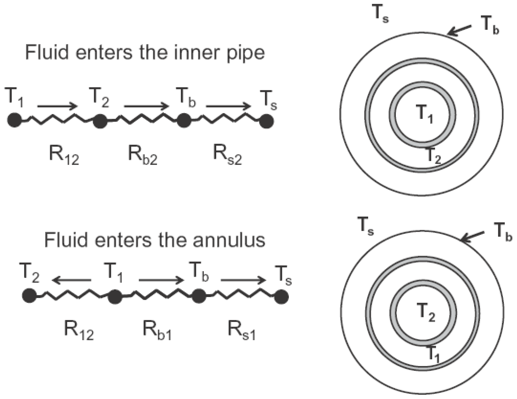
  • CPGE heat removal and release performance under Mode A and Mode B (as shown in Figure 3) were compared. Mode A is commonly selected for heat removal, and Mode B is used for heat release.
  • Various operational modes, i.e., continuous heat removal, intermittent heat removal, and alternative heat removal with heat injection, were reviewed.
  • Applications of CPGEs in indoor heating and electricity power generation sectors were studied.
Future studies may mainly refer to new pipe materials and structures, thermoeconomics and thermodynamic evaluation of CPGEs, simple and fast calculation models, unsteady-state working conditions, on-site experimental studies, annual and long-term operational characteristics monitoring studies (including ground endothermic, exothermic, and recovery progresses), CPGE matrices, and new types of heat carriers. These works will contribute to the technical improvement and wider application of CPGEs.

Author Contributions

Conceptualization, N.R. and X.L.; resources, N.H. and Z.Z.; writing—original draft preparation, G.W.; writing—review and editing, N.R., Y.Z. and Y.W. All authors have read and agreed to the published version of the manuscript.

Funding

This research was funded by the NATIONAL KEY RESEARCH AND DEVELOPMENT PROGRAM OF CHINA, grant number 2023YFC3807700; the UNIVERSITY NATURAL SCIENCE RESEARCH PROJECT OF ANHUI PROVINCE, grant number 2022AH030034; the UNIVERSITY NATURAL SCIENCE RESEARCH PROJECT OF ANHUI PROVINCE, grant number 2022AH010018; and the UNIVERSITY NATURAL SCIENCE RESEARCH PROJECT OF ANHUI PROVINCE, grant number KJ2021JD09.

Conflicts of Interest

The authors declare no conflicts of interest.

Nomenclature

Variable Subscript
cspecific heat capacity, kJ/(kg·K)iinner suface
Dhthe hydraulic diameter of the
cross-section of the annular space
ininlet
oouter surface
eeccentricity, %outoutlet
Ehheat storage efficiency, %sheat storage
hspecific enthalpy, kJ/kg
or convective heat transfer,
W/(m2·K)
wwater
1inner pipe
2outer pipe
Hlength of the CPGE or depth of
the borehole, m
Abbreviation
BHE

borehole heat exchangers
kthermal conductivity, W/(m·K)CCAconcrete core activation
Ldcenter distance of the inner and
outer pipe, (m)
COPcoefficient of performance
CPGEcoaxial pipe geothermal
exchanger
mmass flow rate, kg/s
rradius, mDTRTdistributed thermal response test
Rthermal resistance, (m·k)/W
Rbthree-dimensional borehole
resistance, (m·k)/W
HPheating panel
ORCorganic Rankine cycle
ReRenold NumberTPTthermal exchange
performance test
Qheat, W
ΔTtemperature difference, K or °CTRThermal response test

References

  1. Zhang, X.; Lu, Z.; He, M.; Wang, J. What can Beijing learn from the world megacities on energy and environmental issues? Energy Rep. 2022, 8, 414–424. [Google Scholar] [CrossRef]
  2. Achkari, O.; El Fadar, A. Latest developments on TES and CSP technologies—Energy and environmental issues, applications and research trends. Appl. Therm. Eng. 2020, 167, 114806. [Google Scholar] [CrossRef]
  3. Amir Raza, M.; Karim, A.; Aman, M.M.; Ahmad Al-Khasawneh, M.; Faheem, M. Global progress towards the Coal: Tracking coal reserves, coal prices, electricity from coal, carbon emissions and coal phase-out. Gondwana Res. 2025, 139, 43–72. [Google Scholar] [CrossRef]
  4. Hürpekli, M.; Necati Özsezen, A. Determination of combustion and emission characteristics of liquid Fischer-Tropsch diesel fuel synthesized from coal in a diesel engine. Energy Conv. Manag. 2023, 292, 117351. [Google Scholar] [CrossRef]
  5. Paraschiv, S.; Paraschiv, L.S. Trends of carbon dioxide (CO2) emissions from fossil fuels combustion (coal, gas and oil) in the EU member states from 1960 to 2018. Energy Rep. 2020, 6, 237–242. [Google Scholar] [CrossRef]
  6. Avor, E.P.; Supap, T.; Narku-Tetteh, J.; Muchan, P.; Natewong, P.; Appiah, F.A.; Idem, R. Achieving net-zero CO2 emissions from indirect co-combustion of biomass and natural gas with carbon capture using a novel amine blend. Int. J. Green. Gas Con. 2023, 130, 104005. [Google Scholar] [CrossRef]
  7. Manzini, J.; Hoshika, Y.; Sicard, P.; Anav, A.; De Marco, A.; Sorrentino, B.; Trentanovi, G.; Moura, B.B.; Ferrini, F.; Azzini, L.; et al. Life Cycle Analysis and species-specific net CO2 assimilation model to assess when a new urban forest becomes a carbon sink in a Mediterranean city. Sci. Total Environ. 2025, 959, 178267. [Google Scholar] [CrossRef]
  8. Zhen, Y.; Zheng, H.; Xiao, Q.; Zhang, C.; Wang, C. Estimation method for karst carbon sinks on the basis of a concentration prediction model. J. Environ. Manag. 2025, 373, 123845. [Google Scholar] [CrossRef]
  9. Lu, Z.; Liu, Y.; Zhang, J.; Li, Y.; Guo, X.; Li, X. Carbon-oriented energy system planning using forest carbon sink. Energy 2024, 309, 133010. [Google Scholar] [CrossRef]
  10. Liu, Q.; Wang, S.; Ma, R.; Huang, F.; Li, J.; Ye, S.; Guo, Y. Comparative analysis of forest soil carbon sink and source based on bibliometrics: Development, hotspots, and trends. J. Clean. Prod. 2024, 480, 144106. [Google Scholar] [CrossRef]
  11. Zayani, I.; Ammari, M.; Ben Allal, L.; Bouhafa, K. Agroforestry olive orchards for soil organic carbon storage: Case of Saiss, Morocco. Heliyon 2023, 9, e22910. [Google Scholar] [CrossRef] [PubMed]
  12. Tian, X.; Kang, J.-N.; Dai, M.; Li, X.; Ji, Y.-Z.; Liu, L.-C.; Wei, Y.-M. Unleashing tomorrow’s potential: A comprehensive exploration of risks in carbon capture and storage. Renew. Sustain. Energy Rev 2025, 210, 115174. [Google Scholar] [CrossRef]
  13. Rong, N.; Wang, S.; Chu, C.; Guo, Z.; Liu, K.; Han, L.; Ge, L.; Shi, X.; Wang, G.; Wang, Y. Deactivated Ca-based sorbent derived from calcium looping CO2 capture as a partial substitute for cement to obtain low-carbon cementitious building materials. Constr. Build. Mater. 2024, 454, 139175. [Google Scholar] [CrossRef]
  14. Rong, N.; Wang, J.; Han, L.; Wu, Y.; Mu, Z.; Wan, X.; Wang, G. Effect of steam addition during calcination on CO2 capture performance and strength of bio-templated Ca-based pellets. J. CO2 Util. 2022, 63, 102127. [Google Scholar] [CrossRef]
  15. Li, J.; Li, M.; Dang, C.; Wang, Q.; Dong, L.; Liu, X. Energy and environment analysis of R1234yf/R245fa cascade air source heat pump system with double ejectors. Energy Conv. Manag. 2025, 325, 119404. [Google Scholar] [CrossRef]
  16. Hu, Y.; Shen, B. Development and field demonstration of residential air source integrated heat pump using a three-stage compressor. Energy Build. 2025, 328, 115202. [Google Scholar] [CrossRef]
  17. Hielscher, S.; Wittmayer, J.M.; Progscha, S.; Wientjes, A.; Sharp, H. Speeding-up wind energy developments: Exploring notions of acceleration and justice in regions within Germany and the Netherlands. Energy Res. Soc. Sci. 2025, 119, 103909. [Google Scholar] [CrossRef]
  18. Brouwer, B.; van Bergem, R.; Renes, S.; Kamp, L.M.; Hoppe, T. Does local ownership matter? A comparative analysis of fourteen wind energy projects in the Netherlands. Energy Res. Soc. Sci. 2025, 120, 103891. [Google Scholar] [CrossRef]
  19. Muwanga, R.; Namugenyi, I.; Wabukala, B.M.; Tibesigwa, W.; Katutsi, P.V. Examining social-cultural norms affecting the adoption of solar energy technologies at the household level. Clean. Energy Syst. 2024, 9, 100164. [Google Scholar] [CrossRef]
  20. Khademi, M.M.; Koohshoori, M.S.; Kasaeian, A. Development of a Renewable Energy System Utilizing Solar Dish Collector, Multi Effect Desalination and Supercritical CO2 Brayton Cycle to Produce Fresh Water and Electricity. Energy 2024, 314, 134285. [Google Scholar] [CrossRef]
  21. Bashir, M.F.; Ma, B.; Sharif, A.; Ao, T.; Koca, K. Nuclear energy consumption, energy access and energy poverty: Policy implications for the COP27 and environmental sustainability. Technol. Soc. 2023, 75, 102385. [Google Scholar] [CrossRef]
  22. Vurim, A.; Mukhamedova, N.; Baklanova, Y.; Syssaletin, A.; Akayev, A. Information and analytical system as a promising database used to justify the safety of nuclear energy. Nucl. Eng. Des. 2023, 415, 112704. [Google Scholar] [CrossRef]
  23. Xu, T.; Haas, K.A.; Gunawan, B. Estimating annual energy production from short tidal current records. Renew. Energy 2023, 207, 105–115. [Google Scholar] [CrossRef]
  24. Xu, S.; Yu, F.; Zhang, X.; Wei, D.; Diao, Y.; Li, G.; Huang, H. Investigation of temporal and spatial distribution of tidal energy in Liuheng waterway via coastal acoustic tomography. Renew. Energy 2025, 240, 122180. [Google Scholar] [CrossRef]
  25. Anya, B.; Mohammadpourfard, M.; Akkurt, G.G.; Mohammadi-Ivatloo, B. Exploring geothermal energy based systems: Review from basics to smart systems. Renew. Sustain. Energy Rev. 2025, 210, 115185. [Google Scholar] [CrossRef]
  26. Shahsavar, A.; Goodarzi, A.; Mohammed, H.I.; Shirneshan, A.; Talebizadehsardari, P. Thermal performance evaluation of non-uniform fin array in a finned double-pipe latent heat storage system. Energy 2020, 193, 116800. [Google Scholar] [CrossRef]
  27. Templeton, J.D.; Ghoreishi-Madiseh, S.A.; Hassani, F.; Al-Khawaja, M.J. Abandoned petroleum wells as sustainable sources of geothermal energy. Energy 2014, 70, 366–373. [Google Scholar] [CrossRef]
  28. Kerme, E.D.; Fung, A.S. Heat transfer simulation, analysis and performance study of single U-tube borehole heat exchanger. Renew. Energy 2020, 145, 1430–1448. [Google Scholar] [CrossRef]
  29. Faizal, M.; Bouazza, A.; Singh, R.M. Heat transfer enhancement of geothermal energy piles. Renew. Sustain. Energy Rev. 2016, 57, 16–33. [Google Scholar] [CrossRef]
  30. Beier, R.A.; Acuña, J.; Mogensen, P.; Palm, B. Transient heat transfer in a coaxial borehole heat exchanger. Geothermics 2014, 51, 470–482. [Google Scholar] [CrossRef]
  31. Wang, Z.; Wang, F.; Liu, J.; Ma, Z.; Han, E.; Song, M. Field test and numerical investigation on the heat transfer characteristics and optimal design of the heat exchangers of a deep borehole ground source heat pump system. Energy Convers. Manag. 2017, 153, 603–615. [Google Scholar] [CrossRef]
  32. Ikeda, S.; Choi, W.; Ooka, R. Optimization method for multiple heat source operation including ground source heat pump considering dynamic variation in ground temperature. Appl. Energy 2017, 193, 466–478. [Google Scholar] [CrossRef]
  33. Chen, X.; Rahaman, M.A.; Murshed, M.; Mahmood, H.; Hossain, M.A. Causality analysis of the impacts of petroleum use, economic growth, and technological innovation on carbon emissions in Bangladesh. Energy 2023, 267, 126565. [Google Scholar] [CrossRef]
  34. Radioti, G.; Cerfontaine, B.; Charlier, R.; Nguyen, F. Experimental and numerical investigation of a long-duration Thermal Response Test: Borehole Heat Exchanger behaviour and thermal plume in the heterogeneous rock mass. Geothermics 2018, 71, 245–258. [Google Scholar] [CrossRef]
  35. Alexander, K.; Phillip, S.; Dirk, M. Development of a Long-Term Operational Optimization Model for a Building Energy System Supplied by a Geothermal Field. J. Therm. Sci. 2022, 31, 1293–1301. [Google Scholar]
  36. Anand, J.; Liu, X.; Anees, F.; Li, Y.; Eckman, B.; Malhotra, M. Assessing the impacts of air-sealing on the sizing, operation, and economic feasibility of ground-source heat pumps for electrifying single-family houses in the US. J. Build. Eng. 2024, 98, 111149. [Google Scholar] [CrossRef]
  37. Abdel-Salam, M.R.H.; Zaidi, A.; Cable, M. Field study of heating performance of three ground-source heat pumps in Canadian single-family houses. Energ. Build. 2021, 247, 110959. [Google Scholar] [CrossRef]
  38. Kumar, S.; Murugesan, K. Experimental investigation of thermal performance of ground source heat pump system for summer and monsoon seasons of Himalayan region of India: A case study. Renew. Energy 2024, 237, 121842. [Google Scholar] [CrossRef]
  39. Weeratunge, H.; Aditya, G.R.; Dunstall, S.; de Hoog, J.; Narsilio, G.; Halgamuge, S. Feasibility and performance analysis of hybrid ground source heat pump systems in fourteen cities. Energy 2021, 234, 121254. [Google Scholar] [CrossRef]
  40. Benti, N.E.; Woldegiyorgis, T.A.; Geffe, C.A.; Gurmesa, G.S.; Chaka, M.D.; Mekonnen, Y.S. Overview of geothermal resources utilization in Ethiopia: Potentials, opportunities, and challenges. Sci. Afr. 2023, 19, e01562. [Google Scholar] [CrossRef]
  41. Venomhata, H.D.V.; Oketch, P.O.; Gathitu, B.B.; Chisale, P. Working fluid selection for the geothermal-solar hybrid cycle at Olkaria II power plant in Kenya. Heliyon 2023, 9, e12762. [Google Scholar] [CrossRef] [PubMed]
  42. Agemar, T.; Weber, J.; Schulz, R. Deep Geothermal Energy Production in Germany. Energies 2014, 7, 4397–4416. [Google Scholar] [CrossRef]
  43. Cai, W.; Wang, F.; Liu, J.; Wang, Z.; Ma, Z. Experimental and numerical investigation of heat transfer performance and sustainability of deep borehole heat exchangers coupled with ground source heat pump systems. Appl. Therm. Eng. 2019, 149, 975–986. [Google Scholar] [CrossRef]
  44. Li, C.; Guan, Y.; Yang, R.; Lu, X.; Xiong, W.; Long, A. Effect of inner pipe type on the heat transfer performance of deep-buried coaxial double-pipe heat exchangers. Renew. Energy 2020, 145, 1049–1060. [Google Scholar] [CrossRef]
  45. Deng, J.; Wei, Q.; Liang, M.; He, S.; Zhang, H. Field test on energy performance of medium-depth geothermal heat pump systems (MD-GHPs). Energy Build. 2019, 184, 289–299. [Google Scholar] [CrossRef]
  46. Brettschneider, A.L.; Perković, L. Theoretical analysis of using multiple borehole heat exchangers for production of heating and cooling energy in shallow geothermal reservoirs with underground water flow. Appl. Therm. Eng. 2024, 254, 123914. [Google Scholar] [CrossRef]
  47. Hassan Al-Kbodi, B.; Rajeh, T.; Li, Y.; Zhao, J.; Zhao, T.; Zayed, M.E. Heat extraction analyses and energy consumption characteristics of novel designs of geothermal borehole heat exchangers with elliptic and oval double U-tube structures. Appl. Therm. Eng. 2023, 235, 121418. [Google Scholar] [CrossRef]
  48. Huang, S.; Li, J.; Bai, Z.; Dong, J. Assessment of the effect of heat storage on the production of clean geothermal energy using the medium and deep U-type borehole heat exchanger system. J. Clean. Prod. 2024, 447, 141471. [Google Scholar] [CrossRef]
  49. Biglarian, H.; Abbaspour, M.; Saidi, M.H. Evaluation of a transient borehole heat exchanger model in dynamic simulation of a ground source heat pump system. Energy 2018, 147, 81–93. [Google Scholar] [CrossRef]
  50. Song, X.; Shi, Y.; Li, G.; Yang, R.; Xu, Z.; Zheng, R.; Wang, G.; Lyu, Z. Heat extraction performance simulation for various configurations of a downhole heat exchanger geothermal system. Energy 2017, 141, 1489–1503. [Google Scholar] [CrossRef]
  51. Al-Khoury, R.; Focaccia, S. A spectral model for transient heat flow in a double U-tube geothermal heat pump system. Renew. Energy 2016, 85, 195–205. [Google Scholar] [CrossRef]
  52. Pärisch, P.; Mercker, O.; Oberdorfer, P.; Bertram, E.; Tepe, R.; Rockendorf, G. Short-term experiments with borehole heat exchangers and model validation in TRNSYS. Renew. Energy 2015, 74, 471–477. [Google Scholar] [CrossRef]
  53. Shah, S.K.; Aye, L.; Rismanchi, B. Validations of a double U-tube borehole model and a seasonal solar thermal energy storage system model. Renew. Energy 2022, 201, 462–485. [Google Scholar] [CrossRef]
  54. Shi, Y.; Cui, Q.; Song, X.; Xu, F.; Song, G. Study on thermal performances of a horizontal ground heat exchanger geothermal system with different configurations and arrangements. Renew. Energy 2022, 193, 448–463. [Google Scholar] [CrossRef]
  55. Hasan, N.; Ali, M.H.; Pratik, N.A.; Lubaba, N.; Miyara, A. Improving the thermal performance of vertical ground heat exchanger by modifying spiral tube geometry: A numerical study. Heliyon 2024, 10, e35718. [Google Scholar] [CrossRef]
  56. Agbossou, A.; Souyri, B.; Stutz, B. Modelling of helical coil heat exchangers for heat pump applications: Analysis of operating modes and distance between heat exchangers. Appl. Therm. Eng. 2018, 129, 1068–1078. [Google Scholar] [CrossRef]
  57. Choi, H.K.; Yoo, G.J.; Pak, J.H.; Lee, C.H. Numerical study on heat transfer characteristics in branch tube type ground heat exchanger. Renew. Energy 2018, 115, 585–599. [Google Scholar] [CrossRef]
  58. Wang, G.; Song, X.; Shi, Y.; Zheng, R.; Li, J.; Li, Z. Production performance of a novel open loop geothermal system in a horizontal well. Energy Convers. Manag. 2020, 206, 112478. [Google Scholar] [CrossRef]
  59. Jia, G.; Wang, J.; Ma, C.; Tao, Z.; Zhang, Z.; Ma, Z.; Jin, L. Influence of eccentricity on the thermal performance of pipe-in-pipe heat exchanger utilized for geothermal heating, an experimental study. Appl. Therm. Eng. 2024, 252, 123723. [Google Scholar] [CrossRef]
  60. Jalaluddin; Miyara, A. Thermal performance investigation of several types of vertical ground heat exchangers with different operation mode. Appl. Therm. Eng. 2012, 33–34, 167–174. [Google Scholar] [CrossRef]
  61. Fu, Q.; Ding, J.; Lao, J.; Xie, W.; Wang, W.; Lu, J. Numerical Simulation of Heat Transfer Performance between Molten Salt and Supercritical CO2 in Double-pipe Heat Exchanger. In Proceedings of the 10th International Conference on Applied Energy, Hong Kong, China, 22–25 August 2018; pp. 5741–5746. [Google Scholar]
  62. Gordon, D.; Bolisetti, T.; Ting, D.S.K.; Reitsma, S. Experimental and analytical investigation on pipe sizes for a coaxial borehole heat exchanger. Renew. Energy 2018, 115, 946–953. [Google Scholar] [CrossRef]
  63. Cui, Y.; Zhu, J.; Twaha, S.; Riffat, S. A comprehensive review on 2D and 3D models of vertical ground heat exchangers. Renew. Sustain. Energy Rev. 2018, 94, 84–114. [Google Scholar] [CrossRef]
  64. Bu, X.; Ran, Y.; Zhang, D. Experimental and simulation studies of geothermal single well for building heating. Renew. Energy 2019, 143, 1902–1909. [Google Scholar] [CrossRef]
  65. Gordon, D.; Bolisetti, T.; Ting, D.S.K.; Reitsma, S. Short-term fluid temperature variations in either a coaxial or U-tube borehole heat exchanger. Geothermics 2017, 67, 29–39. [Google Scholar] [CrossRef]
  66. Brown, C.S.; Kolo, I.; Banks, D.; Falcone, G. Comparison of the thermal and hydraulic performance of single U-tube, double U-tube and coaxial medium-to-deep borehole heat exchangers. Geothermics 2024, 117, 102888. [Google Scholar] [CrossRef]
  67. Bär, K.; Rühaak, W.; Welsch, B.; Schulte, D.; Homuth, S.; Sass, I. Seasonal High Temperature Heat Storage with Medium Deep Borehole Heat Exchangers. Energy Procedia 2015, 76, 351–360. [Google Scholar] [CrossRef]
  68. Fang, L.; Diao, N.; Shao, Z.; Wang, Z.; Fang, Z. Study on Thermal Resistance of Coaxial Tube Boreholes in Ground-Coupled Heat Pump Systems. Procedia. Eng. 2017, 205, 3735–3742. [Google Scholar] [CrossRef]
  69. Beier, R.A.; Acuña, J.; Mogensen, P.; Palm, B. Borehole resistance and vertical temperature profiles in coaxial borehole heat exchangers. Appl. Energy 2013, 102, 665–675. [Google Scholar] [CrossRef]
  70. Cengel, Y.A.; Ghajar, A.J. Heat and Mass Transfer: Fundamentals and Applications, 6th ed.; McGraw-Hill Education: New York, NY, USA, 2020. [Google Scholar]
  71. Jingjing, W.; Juntao, D.; Jianguo, Z.; Yongtang, Y.; Jianmin, Z.; Xin, H. A segmented analytical solution heat transfer model of U-tube ground heat exchanger based on finite solid cylindrical heat source method. Geothermics 2025, 125, 103170. [Google Scholar] [CrossRef]
  72. Luo, Y.; Yan, T.; Yu, J. Integrated analytical modeling of transient heat transfer inside and outside U-tube ground heat exchanger: A new angle from composite-medium method. Int. commun. Heat. Mass. Transf. 2020, 162, 120373. [Google Scholar] [CrossRef]
  73. Soltani, M.; Farzanehkhameneh, P.; Moradi Kashkooli, F.; Al-Haq, A.; Nathwani, J. Optimization and energy assessment of geothermal heat exchangers for different circulating fluids. Energy Conv. Manag. 2021, 228, 113733. [Google Scholar] [CrossRef]
  74. Kerme, E.D.; Fung, A.S. Comprehensive simulation based thermal performance comparison between single and double U-tube borehole heat exchanger and sensitivity analysis. Energ. Build. 2021, 241, 110876. [Google Scholar] [CrossRef]
  75. Salilih, E.M.; Abu-Hamdeh, N.H.; Oztop, H.F. Analysis of double U-tube ground heat exchanger for renewable energy applications with two-region simulation model by combining analytical and numerical techniques. Int. Commun. Heat Mass. 2021, 123, 105144. [Google Scholar] [CrossRef]
  76. Raymond, J.; Mercier, S.; Nguyen, L. Designing coaxial ground heat exchangers with a thermally enhanced outer pipe. Geotherm. Energy 2015, 3, 7. [Google Scholar] [CrossRef]
  77. Nian, Y.-L.; Cheng, W.-L. Analytical g-function for vertical geothermal boreholes with effect of borehole heat capacity. Appl. Therm. Eng. 2018, 140, 733–744. [Google Scholar] [CrossRef]
  78. Ma, Z.D.; Zhang, Y.P.; Saw, L.H.; Cui, X.; Jia, G.S.; Jin, L.W. Investigation on local geothermal energy attenuation after long-term operation of ground heat exchanger with considering aquifer effect. Geothermics 2023, 107, 102608. [Google Scholar] [CrossRef]
  79. Lee, S.; Park, S.; Kang, M.; Oh, K.; Choi, H. Effect of tube-in-tube configuration on thermal performance of coaxial-type ground heat exchanger. Renew. Energy 2022, 197, 518–527. [Google Scholar] [CrossRef]
  80. Dong, S.; Yu, Y.; Li, B.; Ni, L. Field test and geologic-thermal-economic analysis of medium-depth borehole heat exchanger. J. Clean. Prod. 2024, 447, 141381. [Google Scholar] [CrossRef]
  81. Oh, K.; Lee, S.; Park, S.; Han, S.-I.; Choi, H. Field experiment on heat exchange performance of various coaxial-type ground heat exchangers considering construction conditions. Renew. Energy 2019, 144, 84–96. [Google Scholar] [CrossRef]
  82. Śliwa, T.; Kruszewski, M.; Zare, A.; Assadi, M.; Sapińska-Śliwa, A. Potential application of vacuum insulated tubing for deep borehole heat exchangers. Geothermics 2018, 75, 58–67. [Google Scholar] [CrossRef]
  83. Chen, H.; Liu, H.; Yang, F.; Tan, H.; Wang, B. Field measurements and numerical investigation on heat transfer characteristics and long-term performance of deep borehole heat exchangers. Renew. Energy 2023, 205, 1125–1136. [Google Scholar] [CrossRef]
  84. Sapinska-Sliwa, A.; Rosen, M.A.; Gonet, A.; Sliwa, T. Deep Borehole Heat Exchangers—A Conceptual and Comparative Review. Int. J. Air-Cond. 2016, 24, 1630001. [Google Scholar] [CrossRef]
  85. Luo, Y.; Guo, H.; Meggers, F.; Zhang, L. Deep coaxial borehole heat exchanger: Analytical modeling and thermal analysis. Energy 2019, 185, 1298–1313. [Google Scholar] [CrossRef]
  86. Song, X.; Wang, G.; Shi, Y.; Li, R.; Xu, Z.; Zheng, R.; Wang, Y.; Li, J. Numerical analysis of heat extraction performance of a deep coaxial borehole heat exchanger geothermal system. Energy 2018, 164, 1298–1310. [Google Scholar] [CrossRef]
  87. Du, D.; Li, Y.; Wang, K.; Zhao, Y.; Hu, Z.; Zhang, W.; Wang, Q. Experimental and numerical simulation research on heat transfer performance of coaxial casing heat exchanger in 3500m-deep geothermal well in Weihe Basin. Geothermics 2023, 109, 102658. [Google Scholar] [CrossRef]
  88. Harris, B.E.; Lightstone, M.F.; Reitsma, S.; Cotton, J.S. Analysis of the transient performance of coaxial and u-tube borehole heat exchangers. Geothermics 2022, 101, 102319. [Google Scholar] [CrossRef]
  89. Wood, C.J.; Liu, H.B.; Riffat, S.B. Comparative performance of ‘U-tube’ and ‘coaxial’ loop designs for use with a ground source heat pump. Appl. Therm. Eng. 2012, 37, 190–195. [Google Scholar] [CrossRef]
  90. Acuña, J.; Palm, B. Distributed thermal response tests on pipe-in-pipe borehole heat exchangers. Appl. Energy 2013, 109, 312–320. [Google Scholar] [CrossRef]
  91. Iry, S.; Rafee, R. Transient numerical simulation of the coaxial borehole heat exchanger with the different diameters ratio. Geothermics 2019, 77, 158–165. [Google Scholar] [CrossRef]
  92. Pan, A.; Lu, L.; Cui, P.; Jia, L. A new analytical heat transfer model for deep borehole heat exchangers with coaxial tubes. Int. commun. Heat. Mass. Transf. 2019, 141, 1056–1065. [Google Scholar] [CrossRef]
  93. Yekoladio, P.J.; Bello-Ochende, T.; Meyer, J.P. Design and optimization of a downhole coaxial heat exchanger for an enhanced geothermal system (EGS). Renew. Energy 2013, 55, 128–137. [Google Scholar] [CrossRef]
  94. Morchio, S.; Fossa, M. Thermal modeling of deep borehole heat exchangers for geothermal applications in densely populated urban areas. Therm. Sci. Eng. Prog. 2019, 13, 100363. [Google Scholar] [CrossRef]
  95. Mokhtari, H.; Hadiannasab, H.; Mostafavi, M.; Ahmadibeni, A.; Shahriari, B. Determination of optimum geothermal Rankine cycle parameters utilizing coaxial heat exchanger. Energy 2016, 102, 260–275. [Google Scholar] [CrossRef]
  96. Daneshipour, M.; Rafee, R. Nanofluids as the circuit fluids of the geothermal borehole heat exchangers. Int. Commun. Heat. Mass. Transf. 2017, 81, 34–41. [Google Scholar] [CrossRef]
  97. Zarrella, A.; Scarpa, M.; Carli, M.D. Short-time step performances of coaxial and double U-tube heat exchangers: Modeling and measurements. HVAC&R Res. 2011, 17, 959–976. [Google Scholar]
  98. Liu, Q.; Zhang, Y.; Zhang, X.; Luo, J.; Zheng, J.; Liu, Y.; Cheng, Y.; Lou, J. Numerical study on the heat transfer performance evaluation, flow characteristics, exergy efficiency, and entropy generation analysis of a novel coaxial geothermal heat exchanger. J. Build. Eng. 2024, 84, 108555. [Google Scholar] [CrossRef]
  99. Liu, Q.; Zhang, Y.; Luo, J.; Zheng, J.; Cheng, Y. Numerical study on heat transfer and flow characteristics of coaxial geothermal heat exchangers with helical finned inner tubes. J. Build. Eng. 2023, 65, 105752. [Google Scholar] [CrossRef]
  100. Rajeh, T.; Al-Kbodi, B.H.; Li, Y.; Zhao, J.; Zhang, Y. Modeling and techno-economic comparison of two types of coaxial with double U-tube ground heat exchangers. Appl. Therm. Eng. 2023, 225, 120221. [Google Scholar] [CrossRef]
  101. Li, Y.; Ma, L.; Xu, W.; Zhu, Q.; Li, W.; Zhao, J.; Zhu, J. Multi-external-chamber coaxial borehole heat exchanger: Dynamic heat transfer and energy consumption analysis. Energy Convers. Manag. 2020, 207, 112519. [Google Scholar] [CrossRef]
  102. Huchtemann, K.; Müller, D. Combined simulation of a deep ground source heat exchanger and an office building. Build. Environ. 2014, 73, 97–105. [Google Scholar] [CrossRef]
  103. Mottaghy, D.; Dijkshoorn, L. Implementing an effective finite difference formulation for borehole heat exchangers into a heat and mass transport code. Renew. Energy 2012, 45, 59–71. [Google Scholar] [CrossRef]
  104. Rajeh, T.; Hassan Al-Kbodi, B.; Li, Y.; Zhao, J.; Zayed, M.E.; Rehman, S. Comparative numerical modeling complemented with multi-objective optimization and dynamic life cycle assessment of coaxial ground heat exchangers with oval-shaped and typical circular-shaped configurations. Appl. Therm. Eng. 2024, 244, 122673. [Google Scholar] [CrossRef]
  105. Rajeh, T.; Al-Kbodi, B.H.; Zayed, M.E.; Li, Y.; Zhao, J.; Rehman, S. Local entropy generation optimization and thermodynamic irreversibility analysis of oval-shaped coaxial ground heat exchangers: A detailed numerical investigation. Int. Commun. Heat. Mass. Transf. 2024, 228, 125650. [Google Scholar] [CrossRef]
  106. Kurevija, T.; Strpić, K. Hydraulic and thermogeological design differences between two-loop vertical and inclined coaxial borehole heat exchangers. Renew. Energy 2018, 117, 314–323. [Google Scholar] [CrossRef]
  107. Dai, C.; Li, J.; Shi, Y.; Zeng, L.; Lei, H. An experiment on heat extraction from a deep geothermal well using a downhole coaxial open loop design. Appl. Energy 2019, 252, 113447. [Google Scholar] [CrossRef]
  108. Cheng, W.-L.; Liu, J.; Nian, Y.-L.; Wang, C.-L. Enhancing geothermal power generation from abandoned oil wells with thermal reservoirs. Energy 2016, 109, 537–545. [Google Scholar] [CrossRef]
  109. Yin, H.; Song, C.; Ma, L.; Gao, L.; Yang, X.; Li, W.; Zhao, J. Analysis of flow and thermal breakthrough in leaky downhole coaxial open loop geothermal system. Appl. Therm. Eng. 2021, 194, 117098. [Google Scholar] [CrossRef]
  110. Mohammadzadeh Bina, S.; Fujii, H.; Tsuya, S.; Kosukegawa, H.; Naganawa, S.; Harada, R. Evaluation of utilizing horizontal directional drilling technology for ground source heat pumps. Geothermics 2020, 85, 101769. [Google Scholar] [CrossRef]
  111. Akram, M.W.; Chen, Q.; Nortz, G.; Nortz, P. Experimental investigation and numerical modeling of an innovative horizontal coaxial ground heat exchanger (HCGHE) for geothermal heat pump applications. Appl. Therm. Eng. 2024, 257, 124492. [Google Scholar] [CrossRef]
  112. Alimonti, C.; Soldo, E. Study of geothermal power generation from a very deep oil well with a wellbore heat exchanger. Renew. Energy 2016, 86, 292–301. [Google Scholar] [CrossRef]
  113. ASHRAE. 2017 Handbook—Fundamentals, SI ed.; ASHRAE: Atlanta, GA, USA, 2017. [Google Scholar]
  114. Olson, J.M. Nanofluids and a Method of Making Nano Fluids for Ground Source Heat Pumps and Other Applications. U.S. Patent 8,580,138, 12 November 2013. [Google Scholar]
  115. Liu, Q.; Tao, Y.; Shi, L.; Zhou, T.; Huang, Y.; Peng, Y.; Wang, Y.; Tu, J. Experimental investigation on the use of CuO/water nanofluid in horizontal spiral-coil ground heat exchanger. Int. J. Refrig. 2023, 149, 204–223. [Google Scholar] [CrossRef]
  116. Togun, H.; Abdulrazzaq, T.; Kazi, S.N.; Badarudin, A.; Kadhum, A.A.H.; Sadeghinezhad, E. A review of studies on forced, natural and mixed heat transfer to fluid and nanofluid flow in an annular passage. Renew. Sustain. Energy Rev. 2014, 39, 835–856. [Google Scholar] [CrossRef]
  117. Pisarevsky, M.I.; Struchalin, P.G.; Balakin, B.V.; Kutsenko, K.V.; Maslov, Y.A. Experimental study of nanofluid heat transfer for geothermal applications. Renew. Energy 2024, 221, 119631. [Google Scholar] [CrossRef]
  118. Zhao, G.; Wang, L.; Liang, Z.; Liu, Q.; Jiang, F. Thermal response analysis of a medium-deep coaxial borehole heat exchanger by circulating CO2. Geothermics 2023, 112, 102746. [Google Scholar] [CrossRef]
  119. Xie, K.; Nian, Y.-L.; Cheng, W.-L. Analysis and optimization of underground thermal energy storage using depleted oil wells. Energy 2018, 163, 1006–1016. [Google Scholar] [CrossRef]
  120. Nian, Y.-L.; Cheng, W.-L.; Yang, X.-Y.; Xie, K. Simulation of a novel deep ground source heat pump system using abandoned oil wells with coaxial BHE. Int. commun. Heat. Mass. Transf. 2019, 137, 400–412. [Google Scholar] [CrossRef]
  121. Li, M.; Shi, Y.; Chen, H.; Liu, C.; Li, H. Study on the heat transfer performance of coaxial casing heat exchanger for medium and deep geothermal energy in cold regions. Renew. Energy 2024, 237, 121666. [Google Scholar] [CrossRef]
  122. Niu, Q.; Ma, K.; Wang, W.; Pan, J.; Wang, Q.; Du, Z.; Wang, Z.; Yuan, W.; Zheng, Y.; Shangguan, S.; et al. Multifactor analysis of heat extraction performance of coaxial heat exchanger applied to hot dry rock resources exploration: A case study in matouying uplift, Tangshan, China. Energy 2023, 282, 128277. [Google Scholar] [CrossRef]
  123. Saadi, M.S.; Gomri, R. Investigation of dynamic heat transfer process through coaxial heat exchangers in the ground. Int. J. Hydrogen. Energy 2017, 42, 18014–18027. [Google Scholar] [CrossRef]
  124. Liu, Z.; Liang, J.; He, Z.; Liu, X.; Liu, H.; Shao, Z. A developed fatigue analysis approach for composite wind turbine blade adhesive joints using finite-element submodeling technique. Eng. Fail. Anal. 2024, 164, 108701. [Google Scholar] [CrossRef]
  125. Liu, Z.; Liang, J.; He, Z.; Liu, X.; Liu, H.; Shao, Z. Finite element submodeling technique-based fatigue analysis and reliability modeling of wind turbine blade trailing edge. Compo. Struct. 2025, 352, 118699. [Google Scholar] [CrossRef]
  126. Liu, Z.; Liu, X.; Zhu, S.-P.; Zhu, P.; Liu, W.; Correia, J.A.F.O.; De Jesus, A.M.P. Reliability assessment of measurement accuracy for FBG sensors used in structural tests of the wind turbine blades based on strain transfer laws. Eng. Fail. Anal. 2020, 112, 104506. [Google Scholar] [CrossRef]
  127. Sliwa, T.; Rosen, M.A. Efficiency analysis of borehole heat exchangers as grout varies via thermal response test simulations. Geothermics 2017, 69, 132–138. [Google Scholar] [CrossRef]
  128. Song, X.; Zheng, R.; Li, G.; Shi, Y.; Wang, G.; Li, J. Heat extraction performance of a downhole coaxial heat exchanger geothermal system by considering fluid flow in the reservoir. Geothermics 2018, 76, 190–200. [Google Scholar] [CrossRef]
  129. Casasso, A.; Sethi, R. Sensitivity Analysis on the Performance of a Ground Source Heat Pump Equipped with a Double U-pipe Borehole Heat Exchanger. Energy Procedia 2014, 59, 301–308. [Google Scholar] [CrossRef]
  130. Zarrella, A.; Emmi, G.; Graci, S.; Carli, M.D.; Cultrera, M.; Santa, G.D.; Galgaro, A.; Bertermann, D.; Müller, J.; Pockelé, L.; et al. Thermal Response Testing Results of Different Types of Borehole Heat Exchangers: An Analysis and Comparison of Interpretation Methods. Energies 2017, 10, 801. [Google Scholar] [CrossRef]
  131. Fang, L.; Diao, N.; Shao, Z.; Zhu, K.; Fang, Z. A computationally efficient numerical model for heat transfer simulation of deep borehole heat exchangers. Energ. Build. 2018, 167, 79–88. [Google Scholar] [CrossRef]
  132. Le Lous, M.; Larroque, F.; Dupuy, A.; Moignard, A. Thermal performance of a deep borehole heat exchanger: Insights from a synthetic coupled heat and flow model. Geothermics 2015, 57, 157–172. [Google Scholar] [CrossRef]
  133. Holmberg, H.; Acuña, J.; Næss, E.; Sønju, O.K. Thermal evaluation of coaxial deep borehole heat exchangers. Renew. Energy 2016, 97, 65–76. [Google Scholar] [CrossRef]
  134. Dai, C.; Shi, Y.; Zeng, L.; Li, J.; Lei, H. Heat Extraction Performance of a Deep Downhole Heat Exchanger. Energy Procedia 2019, 158, 5602–5607. [Google Scholar] [CrossRef]
  135. Caulk, R.A.; Tomac, I. Reuse of abandoned oil and gas wells for geothermal energy production. Renew. Energy 2017, 112, 388–397. [Google Scholar] [CrossRef]
  136. Guo, L.; Zhang, J.; Li, Y.; McLennan, J.; Zhang, Y.; Jiang, H. Experimental and numerical investigation of the influence of groundwater flow on the borehole heat exchanger performance: A case study from Tangshan, China. Energ. Build. 2021, 248, 111199. [Google Scholar] [CrossRef]
  137. Choi, W.; Kikumoto, H.; Ooka, R. Critical comparison between thermal performance test (TPT) and thermal response test (TRT): Differences in heat transfer process and extractable information. Energy Conv. Manag. 2019, 199, 111967. [Google Scholar] [CrossRef]
  138. Choi, W.; Kikumoto, H.; Ooka, R. Two thermal performance test (TPT) datasets of a single U-tube borehole heat exchanger with inlet setpoint temperatures of 30 °C and 40 °C. Data Brief 2018, 20, 1769–1774. [Google Scholar] [CrossRef]
  139. Liu, Y.D.; Beier, R.A. Required duration for borehole test validated by field data. ASHRAE Trans. 2009, 115, 782–792. [Google Scholar]
  140. Li, C.; Jiang, C.; Guan, Y.; Chen, H.; Yang, R.; Wan, R.; Shen, L. Comparison of the experimental and numerical results of coaxial-type and U-type deep-buried pipes’ heat transfer performances. Renew. Energy 2023, 210, 95–106. [Google Scholar] [CrossRef]
  141. Amer, R.; Xue, Z.; Hashimoto, T.; Nagata, T. Distributed fiber optic temperature and strain sensing in cementing and water injection: Insights to well integrity monitoring and multisensing optical fiber cable design. Gas Sci. Eng. 2024, 130, 205430. [Google Scholar] [CrossRef]
  142. Huang, Y.; Zhang, Y.; Xie, Y.; Zhang, Y.; Gao, X. Thermal performance analysis on the composition attributes of deep coaxial borehole heat exchanger for building heating. Energ. Build. 2020, 221, 110019. [Google Scholar] [CrossRef]
  143. Huang, Y.; Zhang, Y.; Xie, Y.; Zhang, Y.; Gao, X.; Ma, J. Field test and numerical investigation on deep coaxial borehole heat exchanger based on distributed optical fiber temperature sensor. Energy 2020, 210, 118643. [Google Scholar] [CrossRef]
  144. Huang, Y.; Zhang, Y.; Xie, Y.; Zhang, Y.; Gao, X.; Ma, J. Long-term thermal performance analysis of deep coaxial borehole heat exchanger based on field test. J. Clean. Prod. 2021, 278, 123396. [Google Scholar] [CrossRef]
  145. Pokhrel, S.; Sasmito, A.P.; Sainoki, A.; Tosha, T.; Tanaka, T.; Nagai, C.; Ghoreishi-Madiseh, S.A. Field-scale experimental and numerical analysis of a downhole coaxial heat exchanger for geothermal energy production. Renew. Energy 2022, 182, 521–535. [Google Scholar] [CrossRef]
  146. Bu, X.; Ma, W.; Li, H. Geothermal energy production utilizing abandoned oil and gas wells. Renew. Energy 2012, 41, 80–85. [Google Scholar] [CrossRef]
  147. Wang, H.; Xu, Y.; Sun, Y.; Zhao, S. Heat extraction by deep coaxial borehole heat exchanger for clean space heating near Beijing, China: Field test, model comparison and operation pattern evaluation. Renew. Energy 2022, 199, 803–815. [Google Scholar] [CrossRef]
  148. Luo, F.; Ma, C.; Liu, J.; Yang, L.; Zhou, W. Effect of gas–liquid phase change of axial rotating heat pipe on fluid-thermal-solid behaviors of high-speed spindle. Appl. Therm. Eng. 2023, 232, 121117. [Google Scholar] [CrossRef]
  149. Zhou, W.; Ma, C.; Yang, L.; Luo, F.; Liu, J. Regulation of thermo-fluid-solid coupling characteristics in high-speed spindle-bearing system for boring machine tool based on sintered-core heat pipes. Int. commun. Heat. Mass. Transf. 2024, 157, 107717. [Google Scholar] [CrossRef]
  150. Zeng, S.; Ma, C.; Liu, J.; Li, M.; Gui, H. Sequence-to-sequence based LSTM network modeling and its application in thermal error control framework. Appl. Soft Comput. 2023, 138, 110221. [Google Scholar] [CrossRef]
  151. Li, M.; Zeng, S.; Hu, J.; Ma, C. Free-mounted cooling plate multi-objective topology optimization method towards precision machine tool heat dissipation: An experimental and numerical study. Int. J. Heat Mass. Tran. 2023, 214, 124394. [Google Scholar] [CrossRef]
  152. Zeng, S.; Liu, J.; Ma, C. Topology optimization in cooling moving heat sources for enhanced precision of machine tool feed drive systems. Int. J. Therm. Sci. 2024, 202, 109065. [Google Scholar] [CrossRef]
  153. Li, M.; Ma, C.; Liu, J. Topology optimization design of cooling water jacket structure for highspeed spindle-bearing system. J. Manuf. Proc. 2023, 102, 1–22. [Google Scholar] [CrossRef]
  154. Li, M.; Ma, C.; Liu, J.; Gui, H.; Zeng, S.; Luo, F. Thermal error prediction of precision boring machine tools based on extreme gradient boosting algorithm-improved sailed fish optimizer-bi-directional ordered neurons-long short-term memory neural network model and physical-edge-cloud system. Eng. Appl. Artif. Intell. 2024, 127, 107278. [Google Scholar] [CrossRef]
  155. Serageldin, A.A.; Sakata, Y.; Katsura, T.; Nagano, K. Performance enhancement of borehole ground source heat pump using single U-tube heat exchanger with a novel oval cross-section (SUO) and a novel spacer. Sustain. Energy Technol. Assess. 2020, 42, 100805. [Google Scholar] [CrossRef]
  156. Kimiaei, S.; Kazemi-Ranjbar, S.; Jalali, A.; Ahmadi, P. A novel three-dimensional numerical model to simulate heat transfer inside a double U-tube borehole with two independent circuits. Int. J. Heat Mass. Tran. 2022, 184, 122243. [Google Scholar] [CrossRef]
  157. Tarrad, A.H. An Analytical Model for the Thermal Assessment of a Vertical Double U-Tube Ground-Coupled Heat Pump System in Steady-State Conditions. Fluid Dyn. Mater. Proc. 2022, 18, 1111–1127. [Google Scholar] [CrossRef]
  158. Quirosa, G.; Torres, M.; Becerra, J.A.; Jiménez-Espadafor, F.J.; Chacartegui, R. Energy analysis of an ultra-low temperature district heating and cooling system with coaxial borehole heat exchangers. Energy 2023, 278, 127885. [Google Scholar] [CrossRef]
  159. Zhou, W.; Li, R.; Chen, Y.; Zhu, S. Numerical Simulation of Mid-Deep Buried Casing Heat Exchanger and its Heating System Application. J. Therm. Sci. 2023, 32, 1445–1454. [Google Scholar] [CrossRef]
  160. Cetin, A.; Kadioglu, Y.K.; Paksoy, H. Underground thermal heat storage and ground source heat pump activities in Turkey. Sol. Energy 2020, 200, 22–28. [Google Scholar] [CrossRef]
  161. Shah, S.K.; Aye, L.; Rismanchi, B. Seasonal thermal energy storage system for cold climate zones: A review of recent developments. Renew. Sustain. Energy Rev. 2018, 97, 38–49. [Google Scholar] [CrossRef]
Figure 1. Diagram of single-U pipe and double-U pipes geothermal heat exchangers. (a) Single-U pipe and (b) double-U pipes.
Buildings 15 00243 g001
Figure 2. Research strategy of this review.
Buildings 15 00243 g002
Figure 3. Structure diagram of a CPGE and two flow patterns in a CPGE. (a) Mode A, (b) Mode B Reprinted with permission from Ref. [67]. 2025, Elsevier.
Buildings 15 00243 g003
Figure 4. Thermal resistance model of a CPGE. Reprinted with permission from Ref. [69], 2025, Elsevier. (T means temperature, R means thermal resistance. Subscripts: 1 means flow path number 1, 2 means flow path number 2, b means borehole, s means ground or soil).
Buildings 15 00243 g004
Figure 5. Components of vacuum insulating tubing. Reprinted with permission from Ref. [82], 2024, Elsevier. (1—coupling, 2—outer steel pipe (e.g., L80), 3—internal coupling insulator and weld, 4—inner steel pipe (e.g., 13CR85), 5—vacuum with getter material). Based on (Helix Oilfield Services Ltd., 2017, Aberdeen, UK).
Buildings 15 00243 g005
Figure 6. Inner pipe welded with steel helix, Reprinted with permission from Ref. [97], 2024, Taylor & Francis Group.
Buildings 15 00243 g006
Figure 7. Schematics of CPGE thermal performance tests. Reprinted with permission from Ref. [81], 2024, Elsevier. (a) System schematics; (b) the unevenly installed thermocouple installation on the outer pipe.
Buildings 15 00243 g007
Figure 8. Use of CPGE in electricity power generation. (a) Direct use (1–5 are the flow paths of the working fluid, and 6–7 are the flow paths of the cooling medium). Reprinted with permission from Ref. [95], 2024, Elsevier; (b) binary cycle power plant, Reprinted with permission from Ref. [93], 2024, Elsevier; (c) organic Rankine cycle power plant (W BHX means CPGE), Reprinted with permission from Ref. [112], 2024, Elsevier.
Buildings 15 00243 g008aBuildings 15 00243 g008b
Table 1. Materials for inner pipes in research.
AuthorsMaterialsThermal Conductivity
[W/(m K)]
Specific Heat Capacity
[J/(kg K)]
Density (kg/m3)
Wang et al. [31]polyethylene pipe0.182100930
Cai et al. [43]high-density polyethylene0.452300950
Gordon et al. [65]high-density polyethylene0.4--
Oh et al. [81]high-density polyethylene0.4--
Śliwa et al. [82]fibre glass0.361-1900
Śliwa et al. [82]vacuum tubes filled with insulation0.006 to 0.0008--
Chen et al. [83]540 polyethylene0.422300950
Table 2. Typical materials for outer pipes.
AuthorsMaterialsThermal Conductivity
[W/(m K)]
Specific Heat Capacity
[J/(kg K)]
Density (kg/m3)
Wang et al. [31]carbon steel544707820
Cai et al. [43]Seamless steel J55404987850
Oh et al. [81]Stainless steel15--
Chen et al. [83]540Steel404987850
Table 3. Properties of different circulating fluids.
AuthorsCirculating FluidDensity (kg/m3)Thermal Conductivity
(W/m·K)
Specific Heat
(J/kg·K)
Dynamic Viscosity
(Pa·s)
Luo et al. [85]water (15 °C)9990.594190---
Alimonti and Soldo [112]diathermic oil (60 °C)7620.1325003.3
Ashrae [113]30% glycol water solution (30 °C)1041.260.45536741.69
Table 4. Thermophysical properties of CuO and Al2O3 nanoparticles.
NanoparticleDensity
(kg/m3)
Heat Capacity
(J/kg·K)
Thermal Conductivity
(W/m·K)
CuO [96]632053276
Al2O3 [96]390088040
Table 5. Summary of varied grouts.
AuthorsGroutThermal Conductivity
(W/m K)
Thermal Diffusivity
(×10−6 m2/s)
Thermal Capacity
(J/kg K)
Density
(kg/m3)
Wang et al. [31]protoplasm4.0-11722283
Deng et al. [45]synthetic mud ball2.0-8502700
Zarrella et al. [130]---1.40.70
Oh et al. [81]cement1.373---
Oh et al. [81]bentonite0.86---
Song et al. [128]conventional cement0.7-20002140
Xie et al. [119]cement0.73---
Song et al. [128]cement0.8-19002140
Chen et al. [83]540 cement mortar0.93 10501800
Table 6. Summary of thermal performance experiments.
AuthorsBorehole Diameter
(mm)
External Diameter
(mm)
Thickness of Pipes
(mm)
Materials of PipesTube
Length
(m)
FluidFlowrate
(L/h)
Flow PatternHeat Transfer ModeGrout or SoilTime Duration
(h)
Inner PipeOuter PipeInner PipeOuter PipeInner PipeOuter Pipe
Wang et al. [31]311110177.8109.19high-density polyethylene pipeJ55-special steel2000water5270Mode Bextractionrock-soil (2.5–5.5 W/mK)118.5
Deng et al. [45]254931593.04.5polyethylene pipecarbon steel2000/2500water1.29 × 104
−2.88 × 10⁴
Mode Bextractionsynthetic mud ball (2.0 W/mK)84
Kurevija and Strpi [106]1106332/40------PEPE100glycol solution---Mode BinjectionSoil50
Gordon et al. [65]98.648. 2894.68.6high-density
polyethylene
high-density
polyethylene
183water2016Mode AInjectionsand and limestone9
Oh et al. [81]1504075------high-density polyethylenestainless steel50water1788Mode Ainjectionbentonite
(grout 0.86 W/mK)
48
Beier et al. [30]115401142.40.4medium- density polyethylenepolyethylene188water2088Mode AinjectionSoil (3.25 W/mK)78
Dai et al. [107] 110---10--thermal proof plastic---1780water6 × 104Mode Bextractionsoil336
Holmberg et al. [133]114401142.40.4polypropylenepolypropylene165Water2088Mode Binjection---78
Disclaimer/Publisher’s Note: The statements, opinions and data contained in all publications are solely those of the individual author(s) and contributor(s) and not of MDPI and/or the editor(s). MDPI and/or the editor(s) disclaim responsibility for any injury to people or property resulting from any ideas, methods, instructions or products referred to in the content.

