Article

Experimental and Finite Element Analysis on the Structural Performance of Lightweight Hollow Slab Prefabricated Staircases

1
School of Civil and Architectural Engineering, Guangxi University of Science and Technology, Liuzhou 545006, China
2
Key Laboratory of Disaster Prevention & Mitigation and Prestress Technology of Guangxi Colleges and Universities, Guangxi University of Science and Technology, Liuzhou 545006, China
3
School of Civil Engineering and Architecture, Nanning University, Nanning 541699, China
4
Guangxi Construction Engineering Track Assembly Precast Concrete Co., Ltd., Liuzhou 545006, China
*
Author to whom correspondence should be addressed.
Buildings 2025, 15(2), 245; https://doi.org/10.3390/buildings15020245
Submission received: 30 December 2024 / Revised: 10 January 2025 / Accepted: 13 January 2025 / Published: 16 January 2025
(This article belongs to the Section Building Structures)

Abstract

:
Prefabricated staircases are crucial components in modern architectural structures, but traditional concrete staircases are too heavy for efficient prefabrication, transportation, and construction. Therefore, this paper proposes a novel lightweight hollow slab prefabricated staircase (referred to as the KXB staircase). The staircase achieves hollow designs for steps and the baseplate by incorporating hollow tubes in the steps and adding polyethylene foam boards in the baseplate. Additionally, a standard prefabricated slab staircase (referred to as the CG staircase) was subjected to static loading tests to analyze failure characteristics, load-deflection curves, and strain distribution. A finite element model was created using ABAQUS (2020) and validated for accuracy through a comparison with experimental results. The results indicate that the novel lightweight hollow-slab prefabricated staircase surpasses conventional slab staircases in load capacity, deflection, and crack control. Furthermore, it achieves a 16% reduction in weight, a 28.6% improvement in load capacity, and a maximum error of 9.9% between the model and experimental results. The novel lightweight prefabricated staircase satisfies engineering requirements, minimizes transportation and hoisting costs, and demonstrates strong application potential.

1. Introduction

With the rapid development of China’s national economy, the demographic dividend is gradually disappearing, leading to a sharp increase in the cost of traditional cast-in-place concrete buildings. Prefabricated buildings, with advantages such as material savings, enhanced construction efficiency, reduced labor demand, and lower construction waste emissions, are being actively promoted in China. Currently, traditional cast-in-situ stairs are widely used in on-site construction activities. The stairs are poured alongside the main structure, ensuring the overall integrity of the building. However, quality issues can easily arise during construction [1]. Prefabricated stairs are typically used in fast-track construction projects and are primarily manufactured in bulk within factories. This allows for better control over material quality and fabrication processes, ensuring high-quality components and reducing construction-related quality issues. Only installation and assembly are required on-site, significantly reducing the construction timeline [2,3]. Their common feature is that both are manufactured using molds, leading to a fixed structural composition. They provide convenient and secure vertical channels between different floors of a building, meeting the requirements for pedestrian movement. Periodic maintenance is necessary in the later stages to ensure the durability and safety of the stairs.
Prefabricated staircases are one of the key prefabricated components in modern buildings, alongside precast composite slabs [4] and prefabricated interior [5] and exterior wall panels, forming the “three-panel system” of prefabricated construction. Traditional monolithic precast reinforced concrete staircases are heavy, requiring larger tower cranes during lifting, which inevitably increases the construction costs and restricts their application and development. Therefore, achieving lightweight components while ensuring the structural performance of prefabricated building elements has become a critical issue to address in the industrialization of construction [6].
Research on the mechanical performance of prefabricated staircases has predominantly focused on the seismic performance of traditional monolithic prefabricated staircases and their influence on the seismic behavior of building structures. During an earthquake, stairs are among the most vulnerable components of a structure. Traditional cast-in-place stairs are poured concurrently with the main structure during construction, causing both to vibrate together during an earthquake [7,8,9,10]. Conversely, prefabricated stairs can be connected to the main structure using alternative methods [11,12,13], enabling separation from the overall structure during an earthquake and thereby reducing reliance on diagonal bracing. For example, Zhang et al. [14] used high-damping rubber bearings for isolation to reduce the adverse diagonal bracing effect of traditionally rigidly connected reinforced concrete staircases on boundary frames under lateral loads, as shown in Figure 1. The study showed that the thickness of high-damping rubber significantly improved the seismic performance of the staircase. Luo et al. [15] investigated the impact of energy-dissipating stairwells on the seismic performance of frame structures and their vibration-reduction effects within the overall structure. Deng et al. [16] examined the performance differences of energy-dissipating stairwells with various support configurations and analyzed the influence patterns of different design parameters on their energy-dissipation and vibration-reduction capabilities. Zhang et al. [13] proposed a staircase isolator that effectively eliminates the diagonal bracing effect, ensuring uniform stress distribution in staircase slabs and structural components. Cong et al. [17] proposed a reinforced concrete frame staircase with separation plates to enhance the seismic performance of staircase frame columns.
In practical engineering, to address the heavy self-weight of traditional monolithic prefabricated staircases, the current approaches involve using transverse segmentation or longitudinal segmentation techniques [18,19]. The transverse segmentation technique divides the staircase into upper and lower segments transversely. Its advantage is that the two segments can be installed independently, ensuring the integrity of the steps. During construction, the position error of the central stair beam can be controlled to ensure proper alignment. However, the inclusion of stair beams and columns increases the net height of the staircase, compromising aesthetics and incurring additional costs. The longitudinal segmentation technique divides the staircase into left and right segments longitudinally. Its advantage is that no stair beams or columns are required between the segments. However, it can result in height differences at the longitudinal joints, necessitating high splicing precision and leading to increased production and construction complexity.
To address the aforementioned issues, recent years have seen scholars conducting research on lightweight monolithic prefabricated staircases. The main weight reduction measures include the application of prestressing. For example, Liu et al. [20] proposed prefabricated prestressed concrete slab and beam staircases. Experiments revealed that prestressed concrete beam staircases reduced the self-weight by over 25% compared to conventional reinforced concrete slab staircases. By appropriately reducing the use of ordinary reinforcement in prestressed concrete slab and beam staircases, their crack resistance and load-bearing capacity were also enhanced. The second method involves the use of hollow structures. For instance, Song [21] proposed a prefabricated hollow slab staircase by introducing longitudinal holes along the staircase baseplate. The study found that compared to solid slab staircases, hollow slab staircases not only reduce the self-weight but also exhibit superior mechanical performance. Li et al. [22] proposed a “double beam + thin slab” design, incorporating hollow PVC pipes in the steps and closure beams at the rest platforms on both ends for a lightweight beam-type staircase. The study indicates that the deflection, load-bearing capacity, and crack width of this staircase comply with standard specifications. Wang et al. [23] designed and proposed a novel lightweight prefabricated staircase system composed of prefabricated staircases and prefabricated hollow platform slabs. The third method involves the use of novel materials [24]. For instance, Shan et al. [25] designed a ribbed thin-slab staircase made of ultra-high-performance concrete (UHPC). Experimental results showed that the cracking load and load-bearing capacity of UHPC staircases were significantly higher than those of conventional reinforced concrete staircases. Additionally, increasing the steel fiber content and reinforcement configuration had a substantial impact on the crack resistance and load-bearing capacity of UHPC staircases. Shen et al. [26] designed a staircase using Geopolymer High-Performance Concrete (GHPC), which demonstrated excellent fire resistance and high load capacity under high-temperature conditions compared to ordinary staircases. Marcinkiewicz et al. [27] designed a novel spiral staircase using ultra-high-strength fiber-reinforced concrete (UHSFRC).
Finite element software is extensively applied in engineering, including studies of underground structures, bridges, and staircases [28,29,30]. Finite element software effectively models the behavior of components under various conditions and is often used for simulations when experiments are constrained by limited resources or funding. Consequently, finite element software has become a commonly used and highly reliable analytical tool for solving practical engineering challenges.
In summary, the research on the mechanical performance of traditional monolithic precast staircases is well-established, with most studies emphasizing improvements in seismic performance. The primary approach to enhancing the seismic performance of precast staircases involves modifying their connection to the main structure. Research on lightweight precast staircases is in its infancy, with current methods focusing on the use of innovative materials or structural modifications to enhance static performance. This paper builds on existing research by proposing a static loading test scheme for KXB and CG staircases, incorporating hollow tubes and polyethylene foam boards into the tread and baseplate. Finite element models of the two prefabricated staircases were developed using ABAQUS (2020) software. By comparing the experimental results with numerical simulation results, the accuracy of the developed finite element models for prefabricated staircases was validated. Finally, parameter analysis identified the key factors influencing the load-bearing capacity of the KXB staircase and their variation patterns, providing references for its design and application.

2. Overview of Specimens

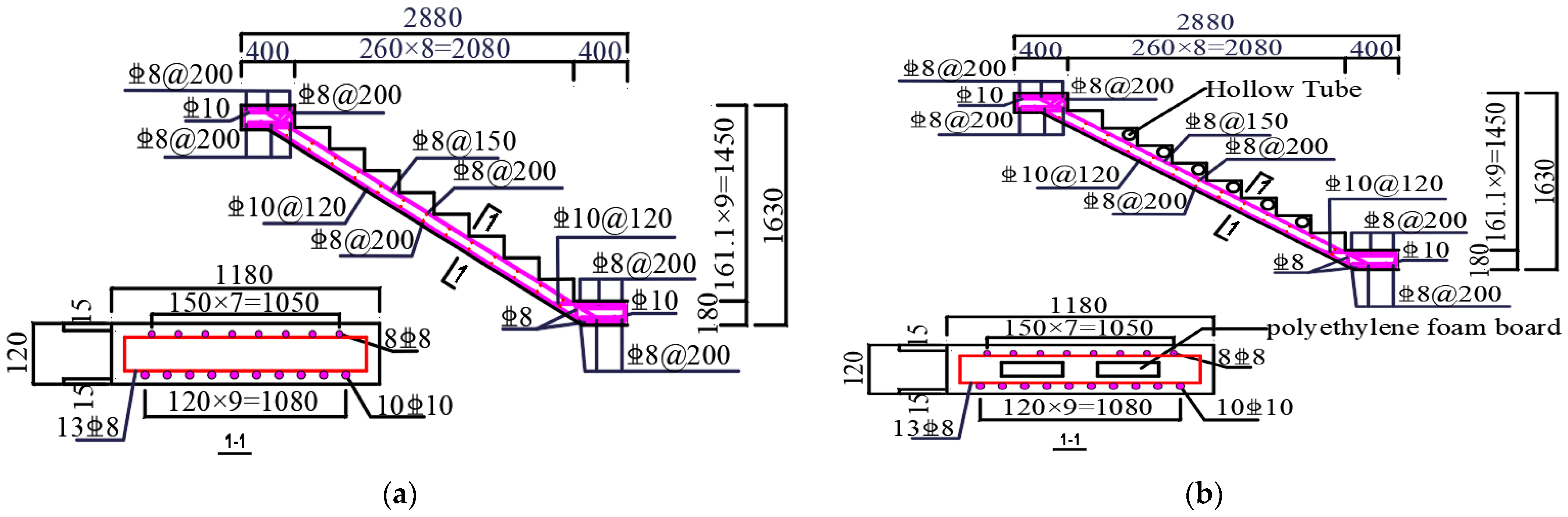
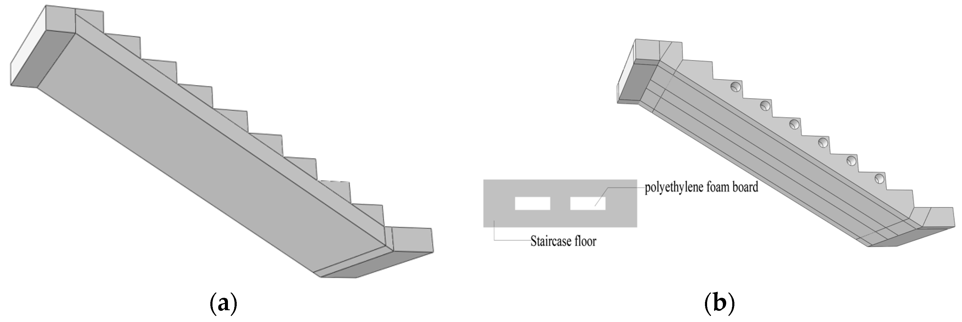
2.1. Design of Components

This design adheres to the Code for Design of Concrete Structures (GB50010-2010) [31], ensuring that the deformation capacity of both stair types complied with the code requirements. The construction standards were guided by the National Architectural Standard Design Atlas (15G367-1~2) [32]. To facilitate comparison, the CG and KXB stairs shared identical dimensions: 2880 mm in length, 1180 mm in width, and 1630 mm in height. The CG stairs were designed strictly according to the standards, without any alterations. Six hollow circular tubes, each measuring 1180 mm in length and 90 mm in diameter, were installed horizontally within the steps of the KXB stairs. Additionally, two polyethylene foam boards, each measuring 2760 mm × 360 mm × 40 mm, were positioned longitudinally inside the precast base plate, spaced 230 mm apart. According to the Load Code for the Design of Building Structures (GB50009-2012) [33], the dead load and live load effects were accounted for and multiplied by safety factors of 1.3 and 1.5 to compute the design values. Subsequently, following the concrete structure design principle [34], the stair boundary conditions (top fixed-hinge support and bottom sliding-hinge support) were incorporated to analyze the critical internal forces, which then informed the reinforcement design. The PKPM (2010-V5.2) software was used for reinforcement design verification to ensure the staircases met the serviceability limit state and ultimate limit state. The reinforcement structures of the conventional slab staircase and the lightweight hollow folded slab staircase are shown in Figure 2, with key parameters and weight reduction rates listed in Table 1.
The concrete strength grade of the two specimens is C30, using the same batch of materials. Concrete cube specimens for the CG and KXB staircases were prepared and cured under identical environmental conditions alongside the components. The average compressive strength of concrete cube test blocks of CG stairs and KXB stairs measured before the test is shown in Table 2. The reinforcement used is HRB400 steel, and the measured yield strength and tensile strength are shown in Table 3.

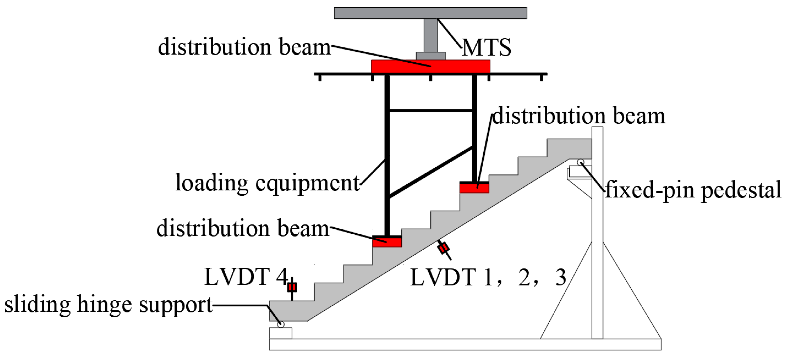
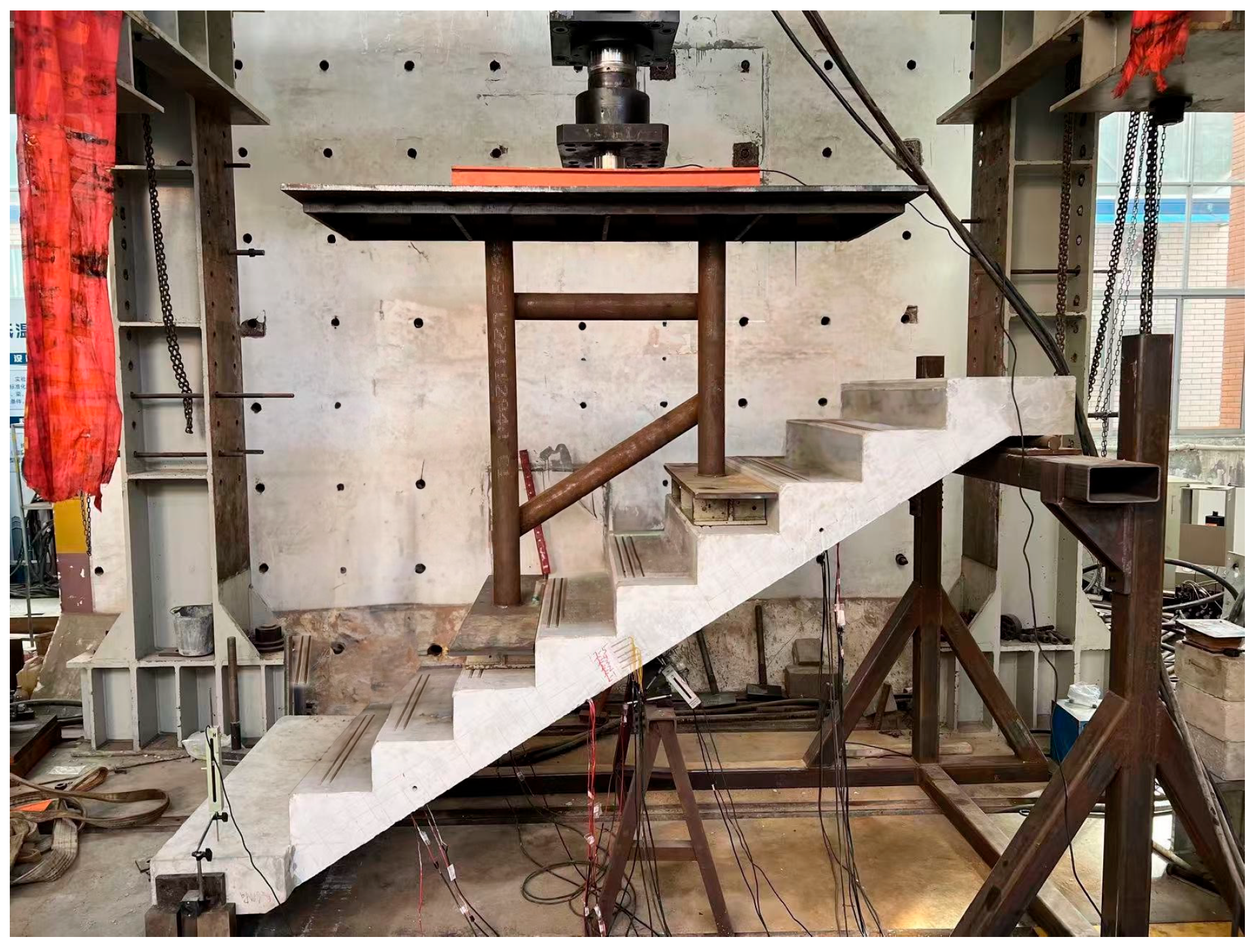
2.2. Experimental Setup and Loading Scheme

Figure 3 illustrates the loading schematic of the prefabricated staircase component. This experiment used a three-point loading method and involved the design of a dedicated testing device to facilitate loading. The device was constructed from 20 mm thick steel plates and circular steel tubes with a wall thickness of 10 mm. To prevent the warping of the steel plate during welding and loading, stiffening ribs were welded around the edges of the upper steel plate to enhance its stability and bending resistance. The staircase’s upper end is supported by a fixed hinge, while the lower end uses a sliding hinge. Synchronization of the loading process is achieved through an electro-hydraulic servo system. The on-site loading conditions of the component are shown in Figure 4.
According to the Standard for Test Methods of Concrete Structures (GB/T50152-2012) [35], the main indicators for a specimen reaching its ultimate bearing capacity are: ① the maximum bending deflection of the component reaches 1/50 of the span, ② the crack width at the position of the tensile reinforcement reaches 1.5 mm, and ③ the concrete in the compression zone is crushed.
The experiment employed a stepwise loading approach with three-point loading. Preloading was conducted before formal loading to verify that the devices, including displacement sensors, strain gauges, and circuit connections, could accurately collect data. After preloading, the load was removed, and the data was reset before initiating formal loading. Formal loading was performed using a force-controlled method. The detailed loading protocol specified that, in the initial stage before the first crack appeared, each load increment was 2 kN and held for 10 min per level. In the second stage, after cracks formed in the component, each load increment increased to 6 kN, was held for 10 min per level, until the component exhibited signs of reaching its ultimate load capacity, at which point loading ceased. Throughout the process, experimental data were collected continuously, and after each load-holding session, a crack observation device monitored and recorded crack data.

2.3. Measurement Point Arrangement

The arrangement of the displacement gauges is illustrated in Figure 3. Displacement gauges 1, 2, and 3 are positioned vertically at the mid-span of the component baseplate, while displacement gauge 4 is located at the lower end of the staircase. Concrete strain gauges 1-1 to 1-5 were mounted on the side surface of the mid-span of the CG staircase’s bottom plate. Concrete strain gauges 2-1 to 2-5 were mounted on the side surface of the mid-span of the KXB staircase’s bottom plate. Strain gauge A12 was affixed to the tensile reinforcement beneath the mid-span of the CG staircase’s bottom plate. Strain gauge B12 was affixed to the tensile reinforcement beneath the mid-span of the KXB staircase’s bottom plate.

3. Experimental Results and Analysis

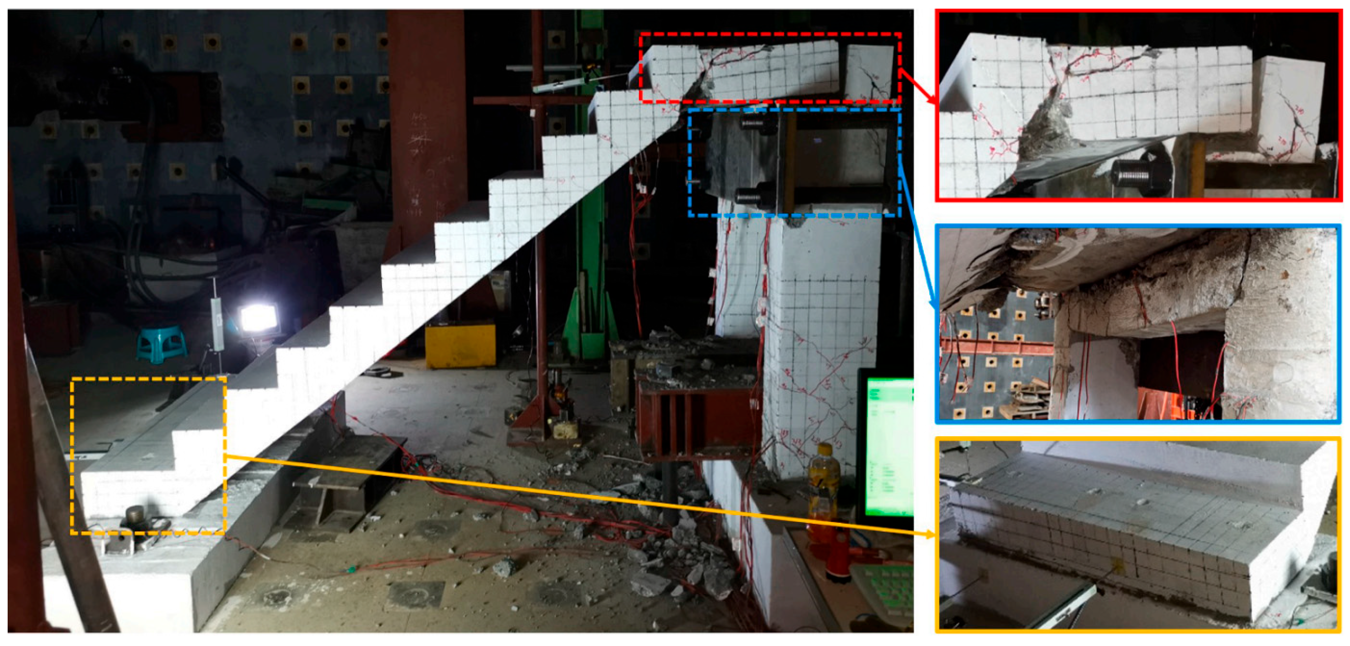
3.1. Experimental Phenomena

During the loading of the CG stair, two small cracks appeared on the side of the baseplate and eight on the baseplate when the load reached 16 kN. The maximum crack width was 0.22 mm. As the load increased, numerous cracks developed at the mid-span and third points of the CG stair. These cracks extended upward along the height of the side baseplate to the inner corners of the stair treads. When the load reached 48 kN, the number of cracks on the side of the baseplate increased to 12, and those on the baseplate to 14. The maximum crack width was 0.75 mm. When the load reached 67 kN, the cracks on the side of the stair baseplate increased to 18, extending toward the inner corners of each stair tread. The cracks on the baseplate also increased to 18, most of which were through cracks. The maximum crack width reached 1.8 mm, indicating that the test had reached its ultimate load capacity, and loading was stopped. Finally, the distribution diagrams of the side cracks and baseplate cracks are presented in Figure 5 and Figure 6.
During the loading of the KXB staircase, when the load reached 24 kN, two small cracks appeared on the side of the stair tread and five on the bottom slab, with the maximum crack width measuring 0.16 mm. As the load increased, numerous cracks appeared at the mid-span and one-third points of the KXB staircase, extending upwards along the height of the bottom slab towards the corners of the stair treads. When the load reached 76 kN, the number of cracks on the stair tread side increased to 10, and on the bottom slab to 12, with the maximum crack width reaching 0.63 mm. When the load reached 92 kN, the cracks on the stair tread side increased to 14, all extending toward the corners of each tread. The cracks on the bottom slab increased to 17, many of which were through cracks, with the maximum crack width reaching 1.72 mm. The staircase reached its ultimate bearing capacity, and the test was then stopped. The final distribution diagrams of the side cracks on the bottom slab and the cracks on the bottom slab are shown in Figure 7 and Figure 8.

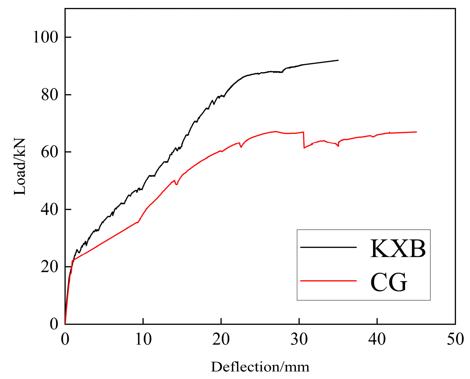
3.2. Load-Deflection Curves

Figure 9 illustrates the load-deflection curves for the CG and KXB staircases. Both staircases undergo clear elastic and elastoplastic phases. The yield loads of the CG and KXB staircases are 22.7 kN and 25.5 kN, respectively, with ultimate bearing capacities of 62.5 kN and 87.2 kN. With a 16% reduction in weight, the ultimate bearing capacity increased by 28.6%. During the elastic phase, both staircases show similar load-bearing performance; however, in the elastoplastic phase, the KXB staircase performs significantly better than the CG staircase. When the crack width at the main tensile reinforcement exceeds 1.5 mm and reaches the ultimate bearing capacity, the bearing capacity of both precast staircases remains stable, indicating their good load-bearing capacity and ductility.

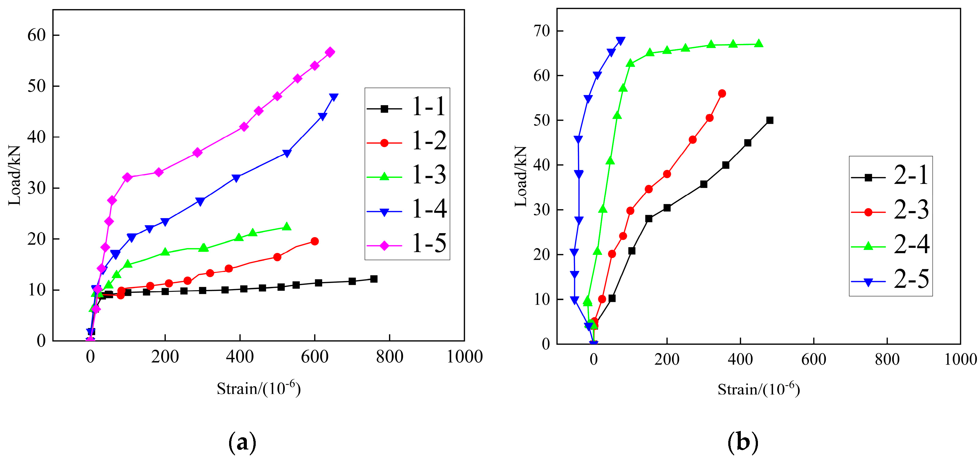
3.3. Load-Strain Curves

Figure 10 shows the load-strain curve for the tensile reinforcement on the lower side of the mid-span. Both staircases’ tensile reinforcement at the mid-span lower side fully develops their tensile capacity and reaches the yield point. Both staircases employ the same reinforcement design, but the KXB staircase uses concrete weight-reduction measures, increasing the reinforcement ratio and enhancing the load-bearing performance. Finite element analysis further shows that increasing the reinforcement ratio of the bottom slab’s tensile reinforcement significantly improves the KXB staircase’s load-bearing capacity.
The 2-2 strain gauge was damaged during transportation, preventing the collection of 2-2 data. Figure 11 illustrates the load-strain curve of the concrete at the mid-span. Except for strain gauges 2-5 and 2-4, all other gauges show positive values during loading, indicating that the concrete is under continuous tensile stress, with strain values increasing as the load increases. For strain gauges 2-5 and 2-4, the strain values are negative in the early stages of loading, indicating that the concrete at these locations is under compression. As the load increases, the strain becomes positive, indicating a transition from compression to tension. A comparison of the load-strain curves of the mid-span concrete from two types of staircases reveals that, under the same load, the strain values in the CG staircase are higher, indicating that the concrete is more fragile and has lower bearing capacity.

4. Finite Element Model Validation and Parameter Analysis

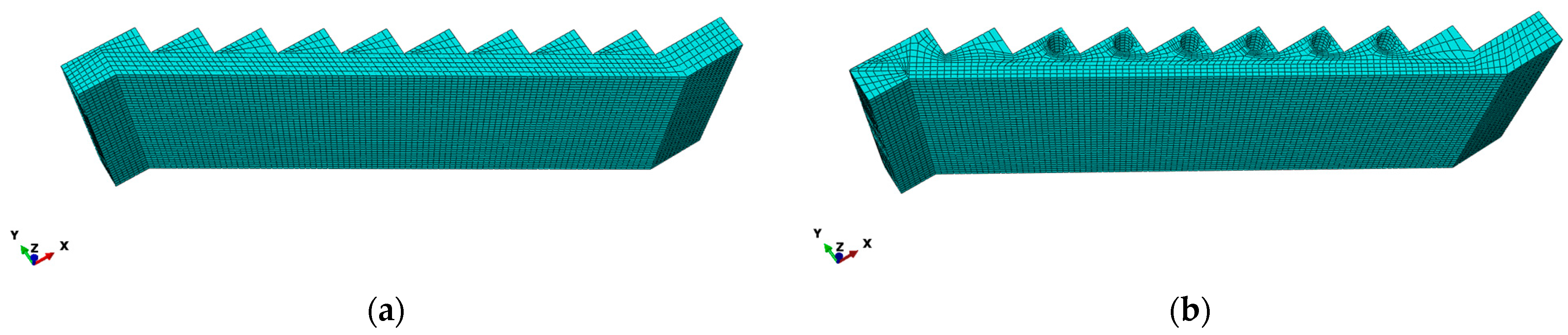
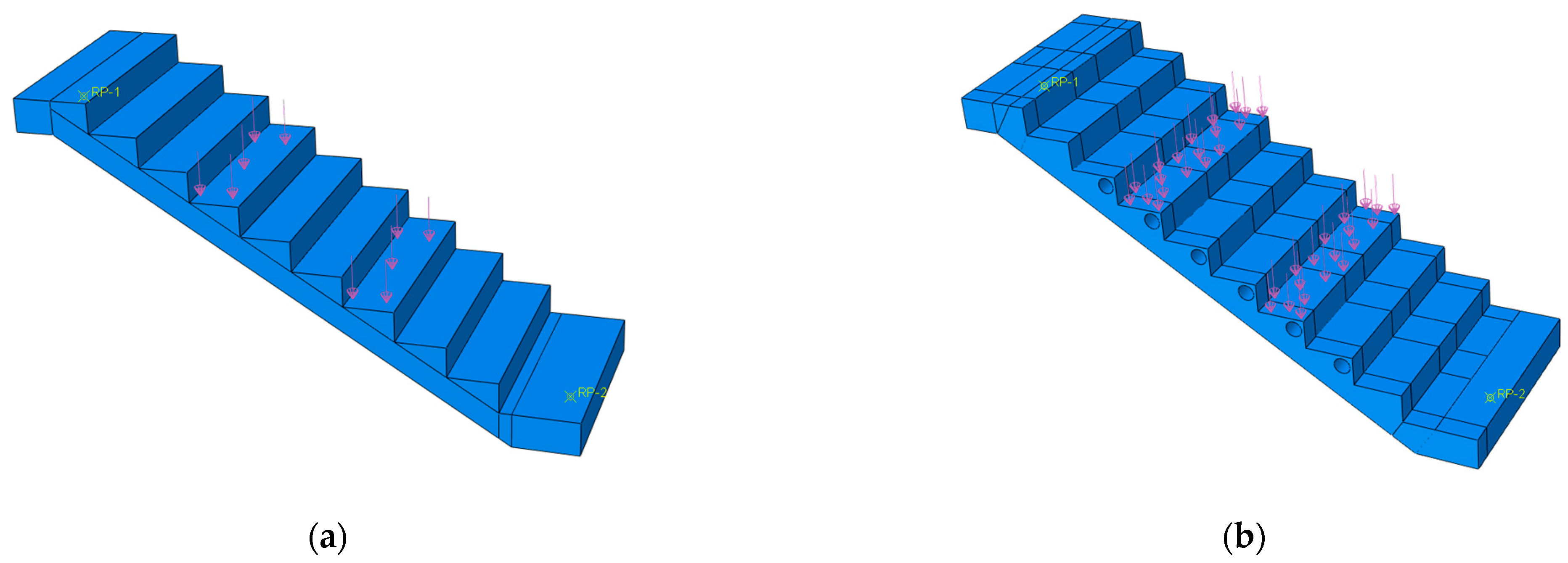
4.1. Model Establishment

Two finite element models for the staircases were developed using ABAQUS (2020) software, as shown in Figure 12. The models’ key parameters and structural details are identical to those of the experimental specimens. Reinforcement was modeled with truss elements (T3D2), and concrete was modeled with solid elements (C3D8R). Effective meshing of the finite element model is essential for ensuring computational efficiency and accuracy. To generate a uniform and structured mesh for the two staircases, each step was first divided longitudinally into 30 mm hexahedral elements. The sweeping technique was applied, with the smallest mesh transition selected along the inner neutral axis. Each step was then divided transversely into 30 mm hexahedral elements. The finite element model of CG stairs has 30,927 elements. The finite element model of the KXB staircase has 41,736 elements. The grid division diagram of the model is shown in Figure 13. The effects of hollow tubes and polyethylene foam boards on the staircase’s load-bearing capacity are minimal and were therefore neglected in this study. Embedded Region constraints were used to simulate the mechanical interaction between the reinforcement and concrete, with the relative slip between them ignored, as shown in Figure 14. The loading type selected was “Pressure”, with “Total Force” as the applied load type, and a static general analysis step was used, as shown in Figure 15.
The Concrete Damaged Plasticity model was chosen for modeling the mechanical behavior of concrete, as it accurately simulates its response under loading [36]. Based on reference [31], the stress-strain relationship for concrete under compression is given by the following equation:
σ = ( 1 d c ) E c ε
d c = 1 ρ c n n 1 + x n x 1 1 ρ c α c ( x 1 ) 2 + x x > 1
ρ c = f c , r E c ε c , r
n = E c ε c , r E c ε c , r f c , r
x = ε ε c , r
In the equation: d c represents the damage evolution parameter for concrete under uniaxial compression; E c represents the elastic modulus of concrete; f c , y represents the uniaxial compressive strength of concrete; ε c , r represents the peak compressive strain at compressive strength; α c represents the reference value for the descending section of the uniaxial compressive stress–strain curve of the concrete.
In the concrete plastic damage model, the density is set to 2400 kg/m3, the elastic modulus to 29,791.5 MPa, Poisson’s ratio to 0.2, the dilation angle to 30°, and the eccentricity to 0.1. f b 0 f c 0 , representing the ratio of the initial equivalent biaxial compressive yield stress to the initial uniaxial compressive yield stress, is set to 1.16. k , representing the stress ratio of the tensile meridian to the compressive meridian under constant stress, is defined as 0.666667.
HRB400 reinforcement is characterized by a density of 7800 kg/m3, an elastic modulus of 2.06 × 10⁵ MPa, and a Poisson’s ratio of 0.3, adhering to the Von Mises criterion. The constitutive model utilizes a bilinear hardening approach [37], with the stress-strain relationship defined as follows:
σ s = E s ε s ε s ε y f y + k ( ε s ε 0 ) ε y < ε s ε s t   0 ε s ε y
k = ( f s t f y ) ( ε s t ε y )
In the equation: σ s represents the stress of the reinforcement; E S represents the elastic modulus of the reinforcement; ε s represents the strain value of the reinforcement; f y represents the yield strength of the reinforcement; ε y represents the yield strain of the reinforcement corresponding to f y ; ε s t represents the peak strain of the reinforcement; k represents the slope of the reinforcement hardening section; f s t represents the ultimate strength of the reinforcement.

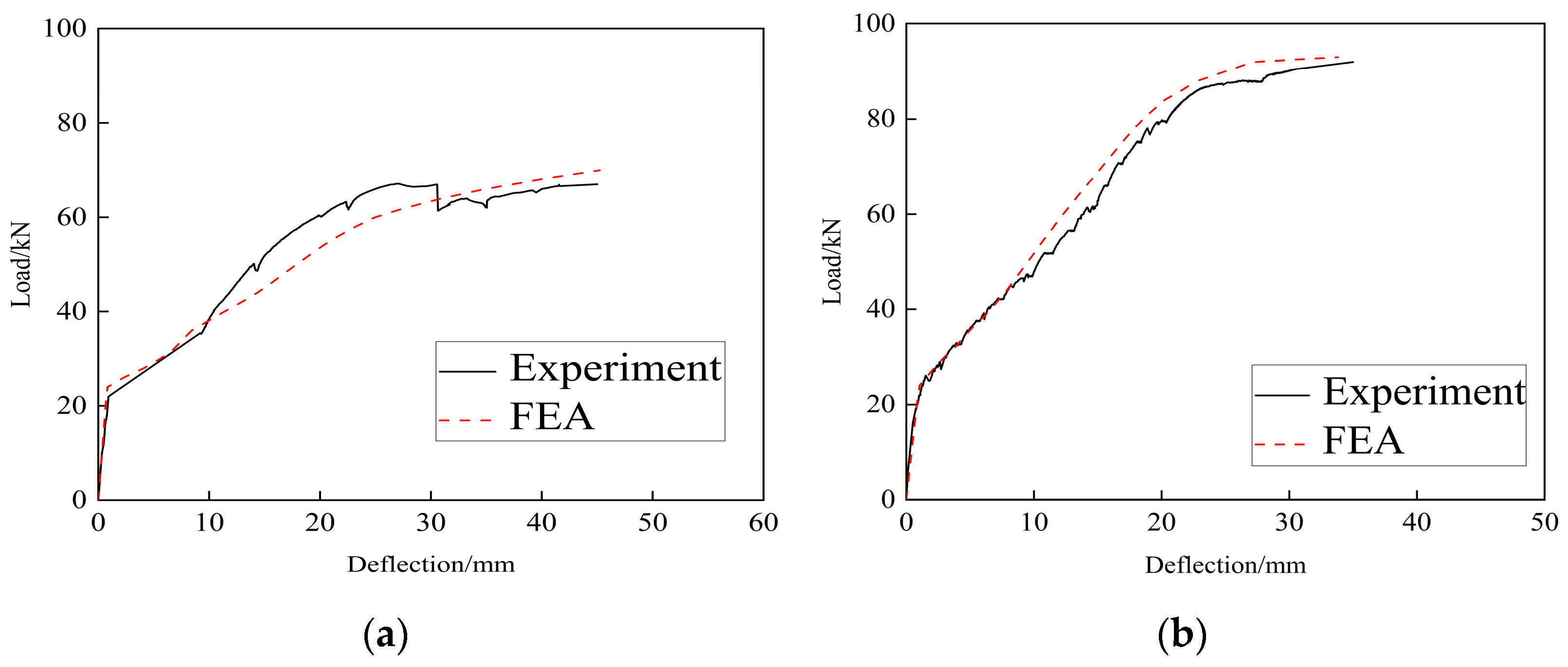
4.2. Validation of the Model

Figure 16 compares the load-deflection curves from the experimental results and finite element simulations. The results show that the load-deflection curves from finite element simulations align with the experimental results, exhibiting linear behavior during the early loading phase and pronounced nonlinear behavior in the later phase. The maximum errors for the yield load and ultimate load are 9.9% and 8.0%, respectively, both within 10%, verifying the accuracy of the two prefabricated staircase models. Table 4 presents the comparison between experimental characteristic values and finite element characteristic values for prefabricated staircases.

4.3. Analysis of Parameters

To examine how tensile reinforcement ratios influence the mechanical behavior of the KXB staircase, parametric analyses were performed with reinforcement ratios set at 0.45%, 0.65%, and 1.1%. Using finite element analysis, load-deflection curves for the KXB staircase under three reinforcement ratios were derived, as illustrated in Figure 17.
Figure 17 shows that during the elastic stage, the curves for the three reinforcement ratios display linear behavior with similar rates of change, indicating that variations in tensile reinforcement ratios have little effect on the stiffness of the KXB staircase. During the elastoplastic and failure stages, the load-bearing capacity of the KXB staircase increases substantially as the tensile reinforcement ratio rises. Specifically, increasing the tensile reinforcement ratio from 0.45% to 0.65% improves the load-bearing capacity of the KXB staircase by about 25%. Similarly, an increase from 0.65% to 1.1% yields an additional 25% enhancement. The ultimate load-bearing capacities of the KXB staircase are 51.8 kN, 68.9 kN, and 91.4 kN under the three reinforcement ratio conditions. In summary, increasing the tensile reinforcement ratio greatly improves the load-bearing capacity of the KXB staircase, and a reasonable increase in the ratio can effectively enhance performance.

5. Conclusions

This study introduces a novel lightweight prefabricated staircase designed in accordance with relevant codes and standards. The weight reduction is achieved by modifying the structural configuration of the staircase. The mechanical properties of two types of prefabricated staircases were investigated through static experiments and finite element analysis, yielding the following conclusions:
(1)
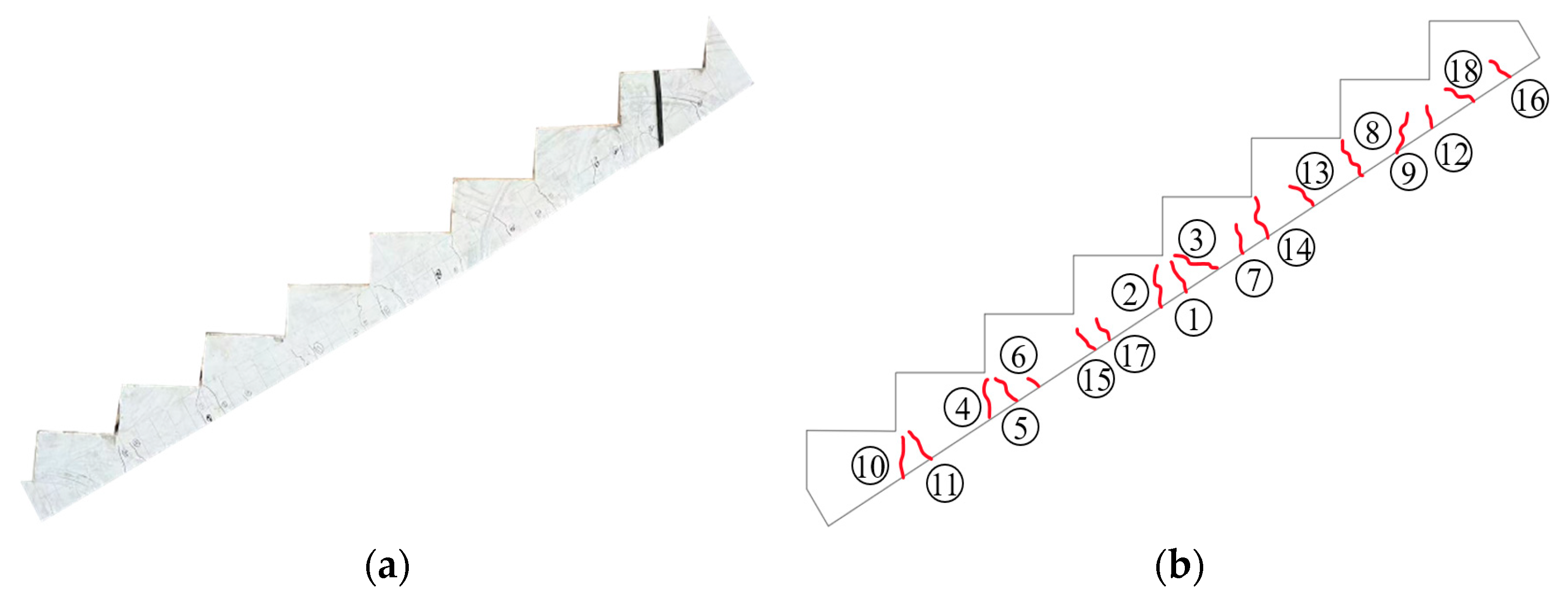
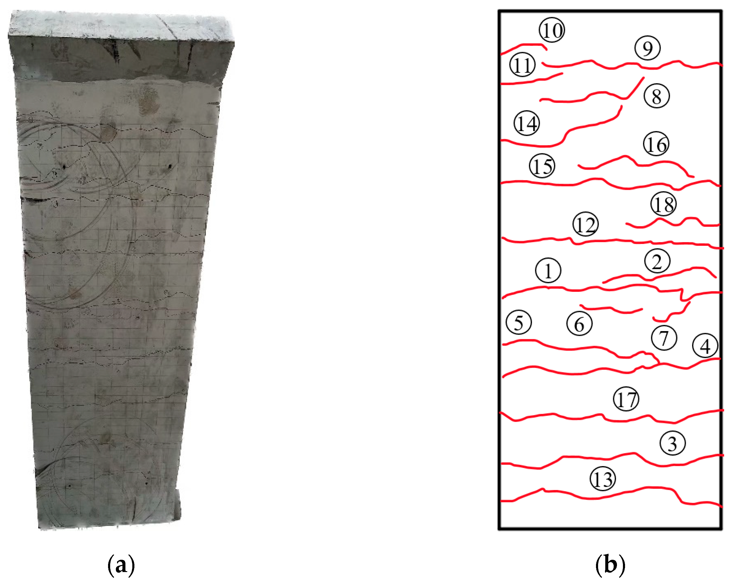
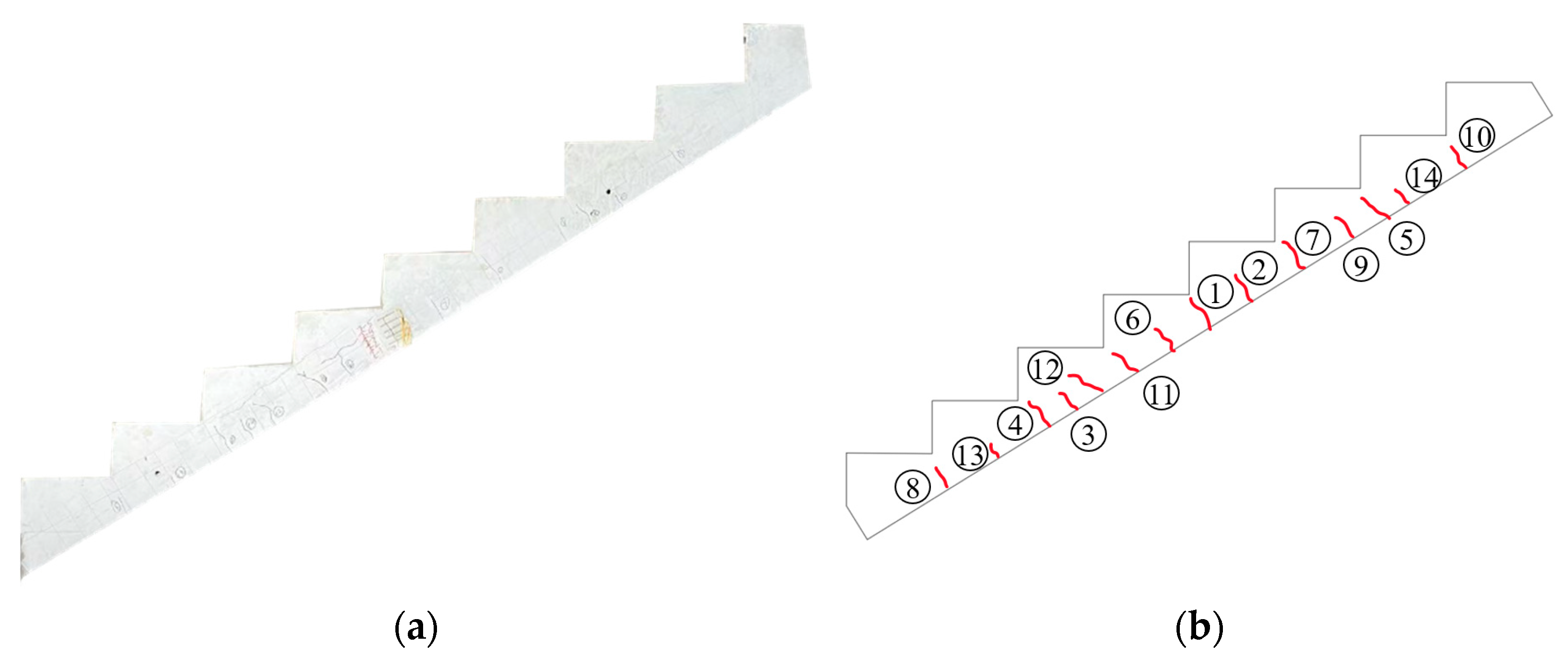
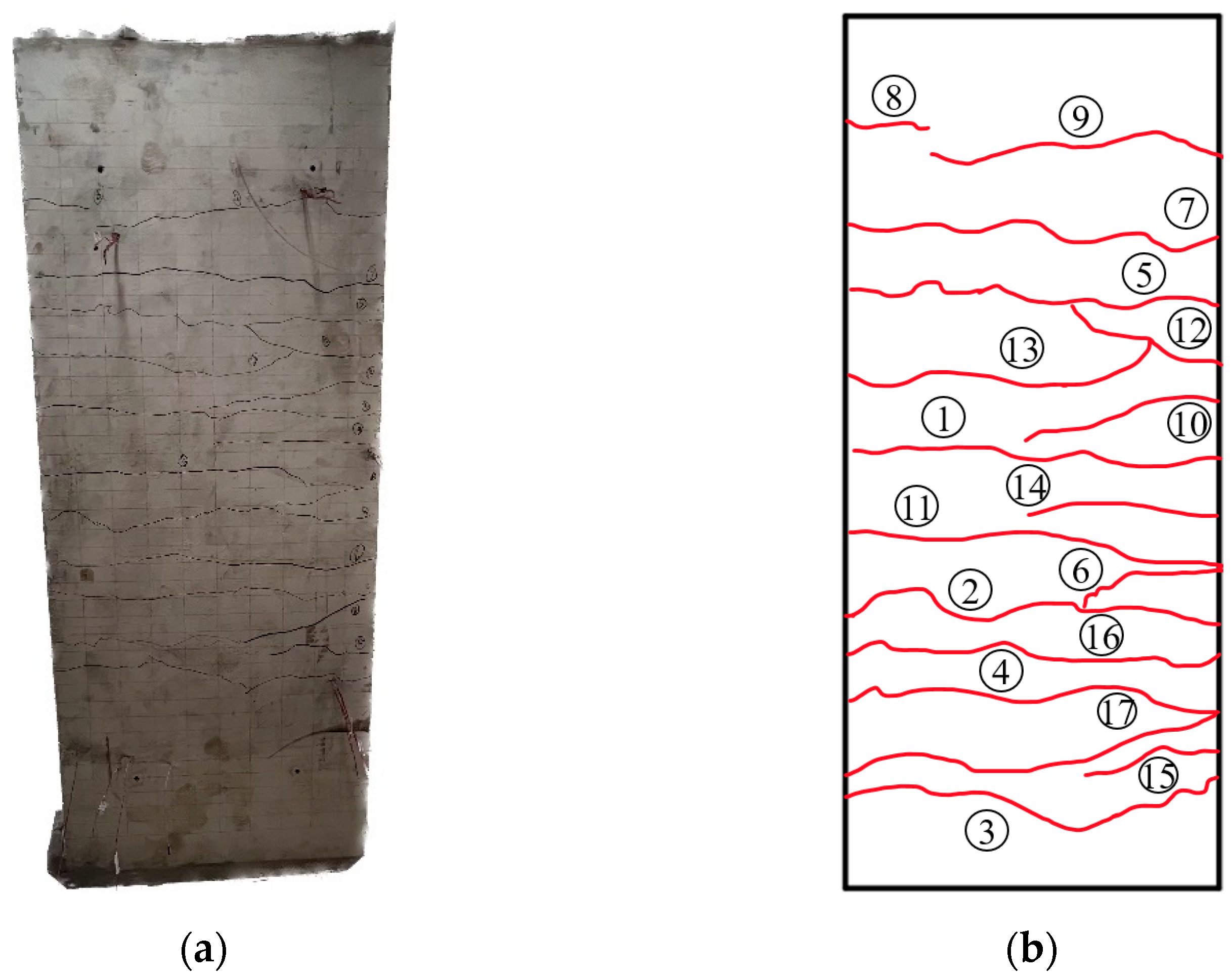
Experimental observations indicate that both types of staircase slabs mainly exhibit through cracks, which eventually propagate along the inner corners of the prefabricated steps, identifying these corners as weak points. Additionally, the KXB staircase shows significantly fewer cracks compared to the CG staircase, highlighting its stronger structural integrity.
(2)
Analysis of load-deflection curves, tensile reinforcement load-strain curves at the slab’s mid-span underside, and mid-span concrete load-strain curves for the two prefabricated staircases reveals that, at a 16% weight reduction, the KXB staircase’s load-bearing capacity is 28.6% higher than the CG staircase. Moreover, under identical loads, the CG staircase exhibits significantly greater strain in its reinforcement and concrete, reflecting its weaker capacity and higher failure susceptibility.
(3)
Experimental results for the two prefabricated staircases indicate that the maximum error between test and finite element analysis results for yield and ultimate loads is within 10%, confirming the accuracy of the developed models.
(4)
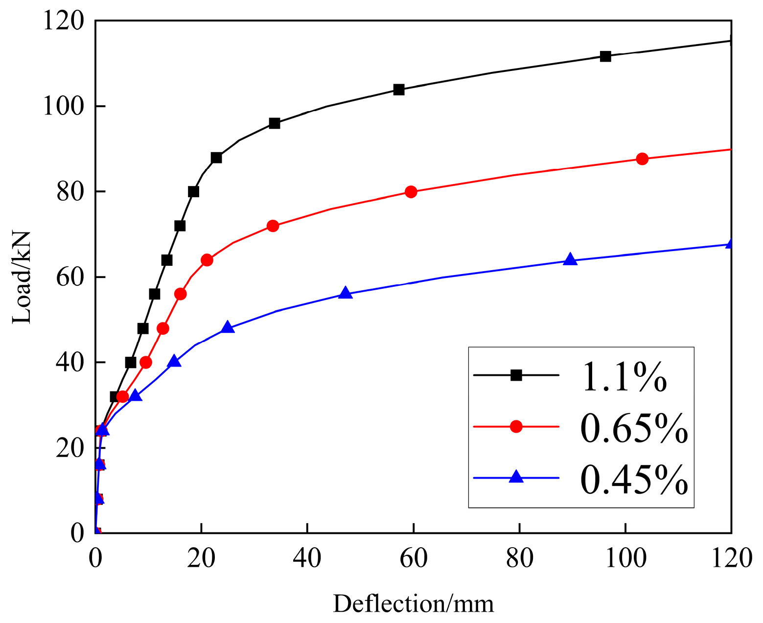
Parametric analysis shows that increasing the tensile reinforcement ratio at the underside markedly improves the KXB staircase’s load-bearing capacity, with a maximum increase of 50%, while the effect on weight reduction remains negligible.
(5)
Compared to conventional staircases, the innovative lightweight staircase offers a significantly reduced weight, streamlining construction logistics and on-site installation. It is well-suited for rapid construction projects, complies with practical engineering requirements, and supports the trend of lightweight development in prefabricated buildings.

Author Contributions

Conceptualization, J.L. and Y.B.; methodology, J.L. and Y.B.; software, Y.B.; validation, J.L., Y.B. and K.Q.; formal analysis, K.Q. and Y.B.; investigation, Y.B.; resources, K.Q.; data curation, Y.B. and K.Q.; writing—original draft preparation, Y.B.; writing—review and editing, K.Q.; visualization, Y.B.; supervision, K.Q.; project administration, J.L.; funding acquisition, J.L. and K.Q. All authors have read and agreed to the published version of the manuscript.

Funding

This work was funded by the Guangxi Key Research and Development Project (No. Gui Ke AB23026065), the Liuzhou Science and Technology Project (No. 2021CBA0105), and the Open Project of First-class Discipline Construction in the School of Civil Engineering and Architecture at Guangxi University of Science and Technology (No. GXKDTJ015).

Data Availability Statement

The original contributions presented in this study are included in the article material. Further inquiries can be directed to the corresponding author.

Acknowledgments

The authors wish to express their appreciation and gratitude to the anonymous reviewers and editors for their insightful comments and suggestions for improving the paper’s quality.

Conflicts of Interest

Author Kang Qin was employed by the company Guangxi Construction Engineering Track Assembly Precast Concrete Co., Ltd. The remaining authors declare that the research was conducted in the absence of any commercial or financial relationships that could be construed as a potential conflict of interest.

References

  1. Liu, C.; Zhang, F.Q.; Zhang, H. Comparative analysis of off-site precast concrete and cast-in-place concrete in low-carbon built environment. Fresenius Environ. Bull. 2020, 29, 1804–1812. [Google Scholar]
  2. Chen, X.A.; Su, S.; Yuan, J.; Li, J.; Lou, F.; Wang, Q. Analyzing the Environmental, Economic, and Social Sustainability of Prefabricated Components: Modeling and Case Study. Sustainability 2023, 16, 342. [Google Scholar] [CrossRef]
  3. Liu, H.; Zainul Abidin, N. A Review on Research of Prefabricated Building Costs: Exploring Collaborations, Intellectual Basis, and Research Trends. Sustainability 2024, 16, 9823. [Google Scholar] [CrossRef]
  4. Xin, G.; Long, G.; Zhao, J.; Zhang, Z. The Effect of Steel Trusses on the Mechanical Performance of Laminated Precast Slabs. Buildings 2023, 13, 1653. [Google Scholar] [CrossRef]
  5. Sah, T.P.; Lacey, A.W.; Hao, H.; Chen, W. Prefabricated Concrete Sandwich and Other Lightweight Wall Panels for Sustainable Building Construction: State-of-the-Art Review. J. Build. Eng. 2024, 89, 109391. [Google Scholar] [CrossRef]
  6. Wu, X.C.; Han, J.Y.; Cui, H.; Li, T.; Bai, X.; He, Y.; Liu, N. A Comparative Review of Recent Research Progress in Prefabricated Buildings in China and Other Countries. Buildings 2024, 14, 1062. [Google Scholar] [CrossRef]
  7. Mir, F.U.H.; Rai, D.C. Experimental and parametric investigation of effects of built-in staircases on the dynamics of RC buildings. Earthq. Eng. Struct. Dyn. 2020, 49, 527–542. [Google Scholar] [CrossRef]
  8. Sun, H.; Zhang, A.; Cao, J. Earthquake response analysis for stairs about frame structure. Eng. Fail. Anal. 2013, 33, 490–496. [Google Scholar] [CrossRef]
  9. Wang, X.; Astroza, R.; Hutchinson, T.C.; Conte, J.P.; Restrepo, J.I. Dynamic characteristics and seismic behavior of prefabricated steel stairs in a full-scale five-story buildings hake table test program. Earthq. Eng. Struct. Dyn. 2015, 44, 2507–2527. [Google Scholar] [CrossRef]
  10. Sezen, H.; Acar, R.; Dogangun, A.; Livaoglu, R. Dynamic analysis and seismic performance of reinforced concrete minarets. Eng. Struct. 2008, 30, 2253–2264. [Google Scholar] [CrossRef]
  11. Higgins, C. Prefabricated Steel Stair Performance under Combined Seismic and Gravity Loads. J. Struct. Eng. 2009, 135, 122–129. [Google Scholar] [CrossRef]
  12. Zhang, R.F.; Zhao, Z.P.; Dai, K.S. Seismic response mitigation of a wind turbine tower using a tuned parallel inerter mass system. Eng. Struct. 2019, 180, 29–39. [Google Scholar] [CrossRef]
  13. Zhang, Y.F.; Tan, P.; Ma, H.T.; Dona, M. Improving the Seismic Performance of Staircases in Building Structures with a Novel Isolator. Cmes-Comp. Model. Eng. 2020, 124, 415–431. [Google Scholar] [CrossRef]
  14. Zhang, C.; Ding, C.; Zhou, Y.; Wang, G.; Shi, F.; Huang, W. Seismic behavior of prefabricated reinforced concrete stair isolated by high damping rubber bearings. Bull. Earthq. Eng. 2022, 21, 1325–1352. [Google Scholar] [CrossRef]
  15. Luo, D.Z.; Deng, X.S.; Zhou, Y.; Zhang, C. Seismic performance analysis of frame structures with damped staircases. Build. Struct. 2019, 49, 80–85. (In Chinese) [Google Scholar]
  16. Deng, X.S.; Luo, D.Z.; Zhou, Y.; Chen, Z.Y. Analysis of energy dissipating performance of damped staircase with different constructions and design parameters. Earthq. Eng. Eng. D 2018, 32, 1–9. (In Chinese) [Google Scholar]
  17. Cong, S.P.; Zhang, Z.; Zheng, Q.; Xu, Z. Seismic behavior of reinforced concrete frame staircase with separated slab stairs. Structures 2021, 34, 4284–4296. [Google Scholar] [CrossRef]
  18. Hu, H.; Li, Z.L.; Liu, H.J.; Jiang, Q.B. Experimental study and finite element analysis on sliced prefabricated staircases. Build. Struct. 2018, 48, 97–106. (In Chinese) [Google Scholar]
  19. Liu, J.M.; Wang, X.J.; Qin, K.; Wei, L.S.; Zhang, H. Research and application of longitudinal segment technology for prefabricated stairs. Struct. Constr. 2020, 42, 1160–1162. (In Chinese) [Google Scholar]
  20. Liu, W.Z.; Cui, S.Q. Experimental study on the flexural performance of prefabricated prestressed concrete stairs. Build. Struct. 2021, 51, 8–15. (In Chinese) [Google Scholar]
  21. Song, S.F. Response Analysis of a New Prefabricated Hollow Slab Staircase under Seismic Action. Master’s Thesis, Harbin Institute of Technology, Harbin, China, 2014. (In Chinese). [Google Scholar]
  22. Li, N.; Xu, Q.G.; Huang, L.P.; Wei, S. Research on type selection and static loading test of lightweight assembled stairs. Eng. Construct. Design 2021, 15, 16–18+40. (In Chinese) [Google Scholar]
  23. Wang, Y.; Sheng, D.; Wang, Y. Research on the Performance of Lightweight Prefabricated Concrete Stairs with a Special-Shaped Hollow Landing Slab. Buildings 2024, 14, 1314. [Google Scholar] [CrossRef]
  24. White, J.; Pleau, R.; Bouchard, F. Innovative Design with Ultra-High Performance Concrete: A Case Study. In Proceedings of the fib Symposium 2004, Avignon, France, 26–28 May 2004. [Google Scholar]
  25. Shan, Y.; Gong, Y.; Wang, Y.; Zhou, Q.; Li, X.; Ding, F.; Kuang, Y. Flexural behavior of ultra-high performance concrete (UHPC) shaped thin-plate ribbed staircases: An experimental and numerical study. Mater. Struct. 2024, 57, 18. [Google Scholar] [CrossRef]
  26. Shen, Y.J.; Wang, Q.; Zhou, Q.; Li, X.; Xiang, Z. Experimental Study on Fire Resistance of Geopolymer High-Performance Concrete Prefabricated Stairs. Buildings 2024, 14, 3783. [Google Scholar] [CrossRef]
  27. Marcinkiewicz, K.; Wells, M. Staircase showcase for ultra-high-strength fibre-reinforced concrete. Proc. Inst. Civil Eng.-Civil Eng. 2014, 167, 131–137. [Google Scholar] [CrossRef]
  28. Mobaraki, B.; Vaghefi, M. The Effect of Protective Barriers on the Dynamic Response of Underground Structures. Buildings 2024, 14, 3764. [Google Scholar] [CrossRef]
  29. Wang, A.; Gao, R.; Chen, Q.; Jin, W.; Fang, P.; Wu, D. An Optimization Study on Continuous Steel Box Girder Bridge Components. Buildings 2025, 15, 124. [Google Scholar] [CrossRef]
  30. Bai, L.; Liang, X.; Xin, L.; Liu, M.; Yu, Z.; Chu, Y. Investigation on the Seismic Performance of RC Frame Buildings with Rubber Isolation Bearing Installed in Staircases. Buildings 2023, 13, 616. [Google Scholar] [CrossRef]
  31. GB50010-2010; Code for Design of Concrete Structures. China Architecture Publishing & Media Co., Ltd.: Beijing, China, 2010. (In Chinese)
  32. 15G310-1~2; Prefabricated Concrete Joint Structure Collection. China Planning Press: Beijing, China, 2015. (In Chinese)
  33. GB50009-2012; Load Code for the Design of Building Structures. China Architecture Publishing & Media Co., Ltd.: Beijing, China, 2012. (In Chinese)
  34. Liang, X.W.; Shi, Q.X. Concrete Structure Design Principle; China Architecture & Building Press: Beijing, China, 2019; pp. 99–108. (In Chinese) [Google Scholar]
  35. GB/T50152-2012; Standard for Test Methods of Concrete Structures. China Architecture Publishing & Media Co., Ltd.: Beijing, China, 2014. (In Chinese)
  36. Chen, H.T.; Sun, Z.; Zhang, X.; Zhang, W. Equivalent Fatigue Constitutive Model Based on Fatigue Damage Evolution of Concrete. Appl. Sci. 2024, 14, 8721. [Google Scholar] [CrossRef]
  37. Shang, F.L. Fundamental of Plasticity; Xi’an Jiao Tong University Press: Xi’an, China, 2018; pp. 14–17. (In Chinese) [Google Scholar]
Figure 1. Failure characteristics of a staircase.
Buildings 15 00245 g001
Figure 2. Reinforcement structure diagram of prefabricated stairs (unit: mm): (a) Reinforcement Layout Diagram and 1-1 Sectional View of CG Staircase; (b) Reinforcement Layout Diagram and 1-1 Sectional View of KXB Staircase.
Buildings 15 00245 g002
Figure 3. Schematic diagram of the test device.
Buildings 15 00245 g003
Figure 4. Test site layout diagram.
Buildings 15 00245 g004
Figure 5. Side-crack diagram of the CG stair baseplate: (a) the actual map of side cracks; (b) side-crack schematic diagram.
Buildings 15 00245 g005
Figure 6. Crack diagram of the CG stair baseplate: (a) the actual diagram of the bottom crack; (b) schematic diagram of bottom crack.
Buildings 15 00245 g006
Figure 7. Side-crack distribution of the bottom slab of the KXB staircase: (a) the actual map of the side crack; (b) side-crack schematic diagram.
Buildings 15 00245 g007
Figure 8. Crack distribution of the bottom slab of the KXB staircase: (a) the actual diagram of the bottom crack; (b) schematic diagram of bottom crack.
Buildings 15 00245 g008
Figure 9. Load-deflection curves of the two staircases.
Buildings 15 00245 g009
Figure 10. Load-strain curve for the tensile reinforcement at the mid-span lower side.
Buildings 15 00245 g010
Figure 11. Load-strain curve of concrete at the mid-span: (a) load-strain curve of concrete at the mid-span of the CG staircase; (b) load-strain curve of concrete at the mid-span of the KXB staircase.
Buildings 15 00245 g011
Figure 12. Finite element model diagram: (a) finite element model diagram of the CG staircase; (b) finite element model diagram of the KXB staircase.
Buildings 15 00245 g012
Figure 13. Diagram of model mesh division: (a) finite element mesh model of the CG staircase; (b) finite element mesh model of the KXB staircase.
Buildings 15 00245 g013
Figure 14. Interaction between reinforcement and concrete: (a) interaction between reinforcement and concrete of the CG staircase; (b) interaction between reinforcement and concrete of the KXB staircase.
Buildings 15 00245 g014
Figure 15. Load application: (a) load application of the CG staircase; (b) load application of the KXB staircase.
Buildings 15 00245 g015
Figure 16. Comparison of experimental and finite element simulation load-deflection curves for prefabricated staircases: (a) comparison of the load-deflection curves from experiments and finite element simulations for the CG staircase; (b) comparison of the load-deflection curves from experiments and finite element simulations for the KXB staircase.
Buildings 15 00245 g016
Figure 17. Load-deflection curves of the KXB staircase under different tensile reinforcement ratios.
Buildings 15 00245 g017
Table 1. The main parameters and weight-loss ratio of prefabricated stairs.
Specimen NumberCGKXB
Upper Longitudinal Reinforcement8Buildings 15 00245 i0018@1508Buildings 15 00245 i0018@150
Lower Longitudinal Reinforcement10Buildings 15 00245 i00110@12010Buildings 15 00245 i00110@120
Distribution Reinforcement13Buildings 15 00245 i0018@20013Buildings 15 00245 i0018@200
Total Weight1830 kg1530 kg
Reduced Weight\299 kg
Weight Reduction Rate\16%
Table 2. Properties of concrete materials.
Specimen NumberCGKXB
Average compressive strength of cube/MPa3230.5
Table 3. Properties of reinforcement materials.
SpecificationBuildings 15 00245 i0018Buildings 15 00245 i00110
Yield Strength/MPa422436
Tensile Strength/MPa618627
Table 4. Comparison of experimental and finite element characteristic values for prefabricated staircases.
Specimen NumberYield LoadUltimate Load
Experiment/kNFEA/kNError/%Experiment/kNFEA/kNError/%
CG22.725.29.962.567.98.0
KXB25.527.98.687.291.44.6
Disclaimer/Publisher’s Note: The statements, opinions and data contained in all publications are solely those of the individual author(s) and contributor(s) and not of MDPI and/or the editor(s). MDPI and/or the editor(s) disclaim responsibility for any injury to people or property resulting from any ideas, methods, instructions or products referred to in the content.

