Article

Intelligent Monitoring System for Deep Foundation Pit Based on Digital Twin

1
Key Laboratory of Earthquake Engineering and Engineering Vibration, Institute of Engineering Mechanics, China Earthquake Administration, Harbin 150080, China
2
Key Laboratory of Earthquake Disaster Mitigation, Ministry of Emergency Management, Harbin 150080, China
3
Department of Civil Engineering, Tsinghua University, Beijing 100084, China
4
Key Laboratory of Digital Construction and Digital Twin, Ministry of Housing and Urban-Rural Development, Beijing 100084, China
5
School of Civil and Hydraulic Engineering, Huazhong University of Science and Technology, Wuhan 430074, China
*
Author to whom correspondence should be addressed.
Buildings 2025, 15(3), 366; https://doi.org/10.3390/buildings15030366
Submission received: 26 December 2024 / Revised: 15 January 2025 / Accepted: 21 January 2025 / Published: 24 January 2025

Abstract

:
Underground space development has significantly increased the depth, scale, and complexity of foundation pit engineering. However, monitoring systems lack mechanical analysis models and fail to predict and control construction risks. Additionally, the foundation pit model could not be updated based on on-site observed data, leading to inaccurate predictions. This study proposes a DT modeling framework for foundation pits, which is used to simulate, predict, and control the risks associated with the entire excavation process. Consequently, based on the DT modeling framework, a DT foundation pit model (DTFPM) was established using modeling and updating algorithms. This study summarizes and identifies the key modeling parameters of foundation pits. A parametric modeling algorithm based on ABAQUS (v2020) was developed to drive the excavation pit modeling process within seconds. Furthermore, an inverse analysis optimization algorithm based on genetic algorithms (GA) and real-time observed deformation was employed to update the elastic modulus of the soil. The algorithm supports parallel computing and can converge within 10 generations. The prediction error of the model after inverse analysis can be reduced to within 10%. Finally, the authors applied DTFPM to establish an intelligent monitoring system. The focus is on real-time and predictive warnings based on the monitoring deformation of the current construction step and the updated model. This study analyzes a Beijing project case to verify the effectiveness of the system, demonstrating the practical application of the proposed method. The results showed that the DTFPM could accurately simulate the deformation behavior of the foundation pit. The system could provide more timely and accurate safety warnings. The proposed method can potentially contribute to the intelligent construction of foundation pits in the future, both theoretically and practically.

1. Introduction

China has made considerable progress in the development and utilization of underground space. The construction of large urban transport hubs and commercial projects has significantly increased the size and depth of deep foundation pits. Excavation projects rapidly evolve towards deeper, larger, and more complex undertakings [1]. The complexity of geological conditions and the uncertainty of theoretical analyses pose significant challenges [2]. However, the monitoring of foundation pits commonly relies on manual data collection and processing, leading to limited data analysis and risk warning capabilities. In recent years, China has witnessed many excavation accidents, which caused significant casualties and property damage. For instance, one notable excavation accident in Hangzhou resulted in many deaths and the destruction of numerous vehicles [3]. The displacement of the excavation pit poses a serious threat to both the structure and human life. Therefore, accurate monitoring and predicting of displacement during the early stages of construction are crucial for preventing potential risks.
In recent years, with the rapid development of computer technology, numerical simulation methods have become an effective means for the design and analysis of foundation pit engineering. However, theoretical and practical challenges exist. Numerical analysis is an essential tool for predicting the deformation of deep excavations. The numerical simulation methods encompass the finite element method (FEM), finite difference method (FDM), boundary element method (BEM), and other similar techniques. In recent years, numerous scholars have employed numerical methods to simulate the deformation of excavation pits and compared the outcomes with field observed data. These have demonstrated numerical analysis methods’ high accuracy and reliability in simulating complex geological conditions, different construction stages, and various support structures [4,5,6,7]. However, due to the inherent uncertainty of soil properties, selecting soil constitutive models and determining parameters present significant challenges. The establishment of numerical models of excavation pits often necessitates the incorporation of numerous empirical parameters, and only through the calibration of the model with field-observed data can the model’s accuracy be guaranteed. Inverse analysis theory [8] can identify soil parameters to fit the field monitoring deformation, such as wall displacement or ground settlement. Typically, in geotechnical inverse analysis problems, due to the uncertainty of soil layer parameters and field measurements, there are multiple approximate solutions rather than a single exact solution. Inverse analysis optimization algorithms can objectively determine soil parameters, such as the gradient method (GM), differential evolution algorithm (DEA), particle swarm optimization algorithm (PSO), genetic algorithm (GA), and others, which have been successfully applied in geotechnical engineering [9,10,11,12]. Professor Holland proposed genetic algorithms at the University of Michigan in 1975 [13]. Many studies have demonstrated that genetic algorithms can identify multiple approximate solutions for inverse analysis problems [14,15,16]. Additionally, many researchers have combined artificial intelligence techniques, such as neural networks and machine learning, to predict the deformation of excavation pits. These methods have significant advantages in handling large amounts of observed data, identifying deformation patterns, and establishing prediction models [17,18,19]. Nevertheless, numerical analysis of excavation pits is predominantly employed for pre-excavation deformation prediction. In addition, numerical modeling of pit excavations usually relies on commercial software such as PLAXIS 2D (v2022) and ABAQUS (v2020). For engineers and technicians, modeling pit excavation can be very challenging due to operational difficulty and cost. Moreover, inverse analysis is frequently conducted after the excavation without the dynamic updating of the model based on field observed data during the excavation process. Consequently, numerical analysis of excavation pits can often fail to predict the actual deformation of the pit in a timely and precise fashion.
On-site monitoring represents the most effective means of observing the deformation of excavation pits. Traditional manual monitoring and management methodologies are no longer adequate to guarantee the safety of large-scale excavation construction. Instead, automated monitoring technologies and intelligent early warning systems are being extensively investigated and implemented. Various monitoring technologies, including automated total stations [20] and three-dimensional laser scanning (3DLS) [21], are commonly employed in pit monitoring. Concurrently, the advent of information technology based on the Internet of Things (IoT) has facilitated the automation of pit monitoring, with online early warning systems evolving from information management [22] to intelligent risk warnings [23]. In the context of construction monitoring of excavation projects, various data collection technologies, such as Global Positioning System (GPS), automated total stations, 3DLS, intelligent sensor networks, etc., produce information typically utilized in isolation. There are a few cases where multiple monitoring and numerical simulation technologies have been applied. The challenge lies in that few systems can manage multi-source heterogeneous data. DT technology can efficiently integrate and utilize these technologies to ensure adequate construction monitoring and risk warning [24,25,26].
The term “digital twin” was first defined in the 2010 NASA report [27], wherein it was described as “multi-physics, multi-scale, probabilistic simulation”. However, the concept of DT was first proposed by Professor Michael Grieves in 2003, who defined it as an “Information Mirroring Model” that includes physical products, virtual products, and the connections between them [28]. In recent years, Tao, F, and others have established a five-dimensional model based on Grieves’ three-dimensional model with the expansion of related theoretical technologies and upgrading application requirements. The model consists of five parts: physical part, virtual part, connections, data, and services [29]. DT technology has been extensively researched and developed in construction engineering [30,31]. Its seamless integration distinguishes DT between the cyber and physical spaces [29,32,33]. At the construction stage, the physical components of the target project have not yet been completed. Consequently, a DT can be created for other related existing projects, related environments, related surroundings, and partially completed target projects to facilitate construction monitoring and management, encompassing aspects such as construction progress, quality, safety, workers, machinery, and materials monitoring and management. However, most current research is focused on monitoring and managing construction progress and quality [34,35]. The development of DT technology in construction safety monitoring and management is still in its infancy [36]. Zijian Ye et al. have proposed a DT-based multi-information intelligent early warning and safety management platform for tunnel construction safety risks. This platform collects and manages multi-source dynamic observed data but does not integrate physical analysis models [37]. Zhe Sun et al. have integrated physical models and on-site observed data, proposing a DT-based framework for intelligent risk prognosis and control of deep excavation [38]. However, this method does not integrate intelligent inverse analysis algorithms and instead requires experienced technical personnel to modify model parameters for model updates. Moreover, a universal safety early warning management platform has yet to be established.
The above research significantly contributed to developing intelligent monitoring and early warning systems for deep foundation pits. However, several challenges need to be addressed. First, the dynamic nature of excavation and the variability of support structures and soil properties make numerical modeling of deep foundation pits highly complex. Currently, there is a lack of standards for numerical modeling of deep foundation pits, which makes it difficult for parametric modeling. Secondly, a significant discrepancy is often observed between the results of numerical simulations and actual observation. However, most inverse analyses of model parameters are conducted following the completion of construction, and the models are not updated in real time based on on-site observed data. Consequently, the current safety monitoring and early warning systems for deep foundation pits do not integrate numerical models, which impedes the ability to provide precise safety warnings in real time. Moreover, the utilization of DT technology in the monitoring and management of deep foundation pit construction is still in its early stages. There is a pressing necessity to establish a safety warning system based on DT technology to enhance the efficacy of construction safety monitoring and management.
To address the gaps mentioned above, the specific objectives of this study are as follows: (1) to propose a DT-based architectural framework for deep foundation pit modeling; (2) to investigate a parametric modeling method for pits with complex geological environments and multiple support structures, as well as a capability for dynamic construction simulation; (3) to investigate an intelligent inverse analysis optimization algorithm to update the pit model in real-time based on field monitoring data; (4) to explore the effectiveness of intelligent monitoring system using DT technology in deep foundation pit excavation projects.
The structure of this paper is as follows: Section 2 provides an overview of the DT-based deep foundation pit modeling framework; Section 3 describes the parametric modeling of deep foundation pits and the inverse analysis algorithm for model updating; Section 4 outlines the architecture of the DT-based deep foundation pits monitoring system; Section 5 presents a case study of a deep foundation pit construction project; Section 6 provides a summary of the conclusions and outlines future work.

2. Digital Twin Framework for Deep Foundation Pit Modeling

The application of DT technology is initiated by the construction of a model representing the application object. This study references Tao’s five-dimensional model [29] to establish the architecture of a DT for deep foundation pits, as shown in Figure 1. The model is divided into five parts: (1) the physical space of deep foundation pits construction; (2) the virtual space of finite element simulation; (3) DT data; (4) intelligent early warning web services; and (5) connections between the parts. The following section will provide a detailed introduction to each part.

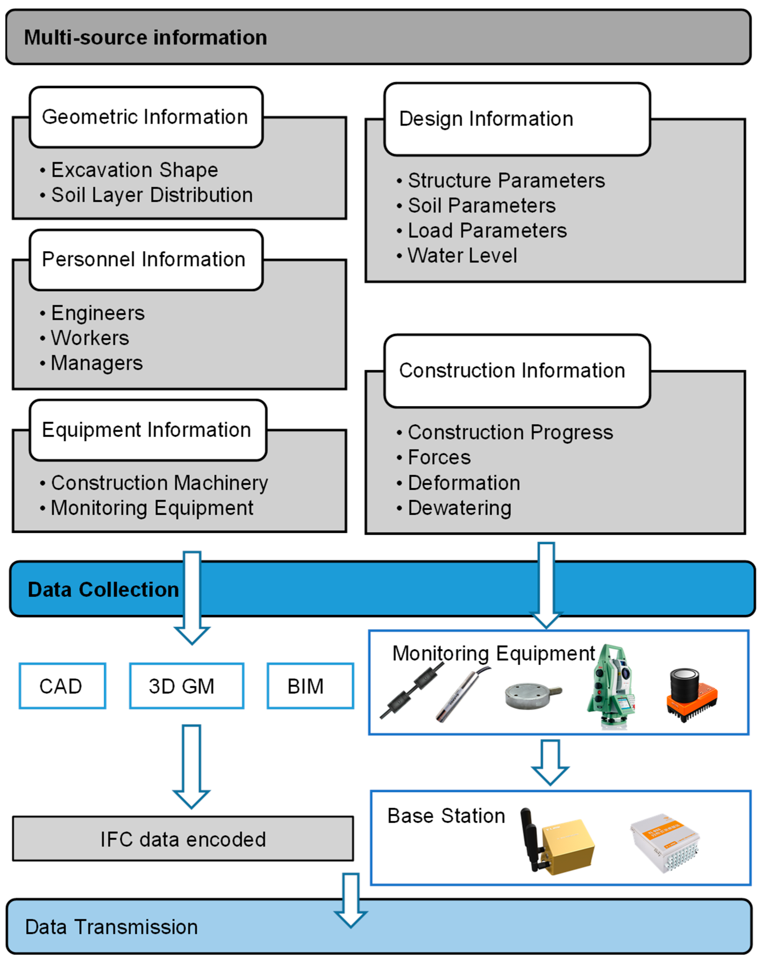
2.1. The Physical Space

The excavation is a dynamic process, and the multi-source information present in the physical space must be collected and transmitted to the data center, as illustrated in Figure 2. Geometric information, personnel information, and equipment information are typically conveyed by the CAD model, 3D geological model (3DGM), and building information model (BIM). Those models can be transmitted to the twin database after being converted using Industry Foundation Classes (IFC). Design information about support structures, soil, loads, and water levels is subject to change during construction. This information can be collected in real-time using sensors, automated total stations, and 3D laser scanning (3DLS) and then transmitted to the twin database after compilation.

2.2. The Virtual Space

In the virtual space, a virtual model of the deep foundation pit is established as a mapping of the physical entities within the pit, which encompasses the geometric model (GM), physical model (PM), behavior model (BM), and rule model (RM). The GM contains information such as the shape and dimensions of the pit, stratigraphic information of the soil, and the positional relationships of support components, which can be established using 3D modeling software. The PM includes mechanical information about the soil, loads on support structures, etc., which can be established using finite element analysis software. During the excavation process, the geometric shape and mechanical parameters of the pit will undergo dynamic changes, which will be reflected in the BM. The RM includes relevant specifications for pit design, construction, and monitoring, as well as patterns and experiences based on historical data. These four types of models are integrated and fused to form a complete simulation model, which is verified and updated through optimization algorithms to ensure consistency with the physical entity.
The architecture for deep foundation pit simulation modeling and data updating based on the DT proposed in this study is shown in Figure 3. However, the major challenge is establishing multi-dimensional, multi-temporal, and spatial scales and dynamically evolving numerical models of foundation pits based on engineering requirements while considering efficiency and accuracy. The objective is to develop a parametric modeling algorithm that can rapidly establish a FEM of the deep foundation pit with the necessary parameters. In the meantime, an inverse analysis optimization algorithm should be developed to update the model dynamically in real-time based on observed data. Both algorithms will be described in detail in Section 3.

2.3. Services

It is necessary to encapsulate numerical models, optimization algorithms, and data into services to meet the needs of engineering applications. A web-based intelligent monitoring system is developed, as illustrated in Figure 4, which serves workers, engineers, and managers. Computing services, web services, and data services are deployed on different servers, enabling cloud computing and reducing users’ software and hardware requirements. The web services manage excavation progress, sensors, observed data, and DT models. The computing services integrate parametric modeling algorithms and inverse analysis optimization algorithms for DT modeling and model updates. The excavation progress, modeling, observed, and risk data are stored and visualized on the web page. The system will be introduced in detail in Section 4.

2.4. DT Data and Connection

The DT data, which are the driving force behind DT, are comprised primarily of observed data, modeling data, simulated data, updated data, empirical data, and risk data. The dynamic mapping between a physical and a virtual model is achieved by fusing these twin data. The process of data fusion is illustrated in Figure 3.
Data connections enable the interconnection and intercommunication of the various parts of the DT model. These connections primarily involve the interaction between the physical space, virtual space, and web services with the twin database, as shown in Figure 1.
The data connection between the physical and virtual space occurs mainly between the sensors and the finite element model. Smart collection devices collect observed data from the site in real time, which are then uploaded to the cloud server through a wireless gateway. Multi-source and heterogeneous data must be compiled into a standard data format. Standardized data are more conducive to data interaction. The author has developed corresponding data interfaces for different hardware, converting the sensor monitoring results into sequences of time and deformation. The system includes a set of relational database models, as shown in Figure 5. The sensors are associated with the numerical model through IDs. The results of the analyses include coordinates of measurement points, construction stages, and displacements. The engineer needs to manually associate the sensors with the analysis model before the initial analysis. The basis for data correlation includes IDs, time, and construction stages.
Different servers interact with each other using the HTTPS protocol. The web server transmits computational instructions to the computing server, which drives model FNA analysis and inverse analysis. The computing server then sends the calculation results back to the web server for the user to view. All data are stored in real time in the data server.

3. DT Foundation Pit Modeling in the Virtual Space

This study developed two algorithms, parametric modeling algorithms, and inverse analysis algorithms, to establish the DT foundation pit model (DTFPM). The following section will introduce these two algorithms.

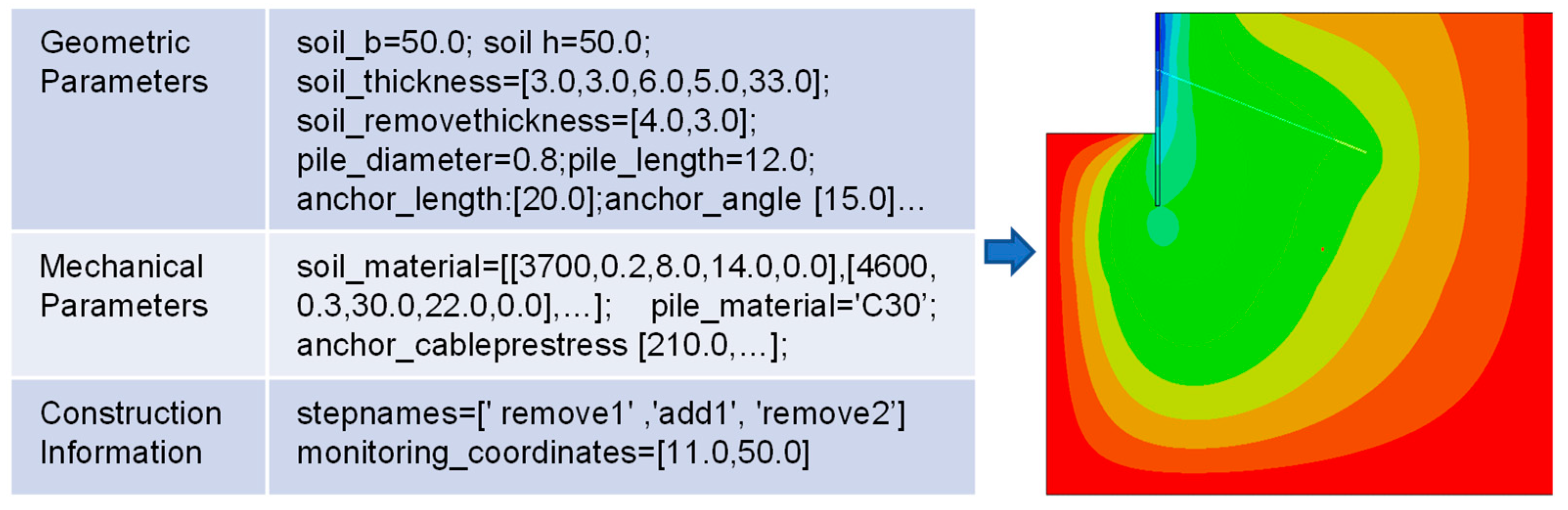
3.1. Parametric Modeling of Foundation Pit

This study presents a parametric modeling algorithm for excavation pits developed based on ABAQUS (v2020). This algorithm can be used to model multiple types of support and is well-suited to complex geologic conditions. Through analysis of many engineering cases, the deep foundation pit types are categorized into five basic subtypes, along with their respective combinations: open-pit excavation, soil nail support, pile–anchor support, pile–brace support, and wall–brace support. To ensure the reliability of the ABAQUS model, the author compared it with PLAXIS (v2022), a software widely used in engineering practice. The author compiled the modeling parameters for the case study and established both ABAQUS and PLAXIS models. The displacement contours and key measurement point deformations were extracted from both models. By adjusting the parameter settings in the ABAQUS model, the analysis results of the two models were made to align closely to ensure that the ABAQUS model can be applied to actual engineering projects.
The DTFPM employs the M-C and Hardening Soil (HS) model. The M-C model is simple, and most parameters can be found in geological exploration reports, leading to its widespread use in geotechnical engineering. However, the M-C model cannot account for essential deformation characteristics such as increased soil modulus with stress, which may result in less reasonably calculated deformation of deep foundation pits. The HS model, on the other hand, can consider the hardening characteristics of soft clays, and its calculation results provide a more reasonable estimate of both wall deformation and soil deformation behind the wall, making it suitable for numerical analysis of deep foundation pits in sensitive environments. However, the HS model is not built-in in ABAQUS. The authors have redeveloped the modified HS (MHS) model via the user-defined subroutine UMAT and embedded it into ABAQUS. The MHS model is presented with several improvements. These include reforming the yield function, the hardening law, and the rederivation of the constitutive equations to ensure the desired stress–strain relation. However, the MHS model requires more parameters than the M-C model and obtaining a complete set of model parameters can be challenging. Therefore, this study will conduct an inverse analysis of soil parameters based on observed data to improve the calculation accuracy of both the M-C and MHS models.
The parametric modeling algorithm was developed using Python (v2.7.15) based on the ABAQUS modeling scripts. ABAQUS provides a scripting interface that can directly communicate with the kernel. The script files comprise a series of pure ASCII format Python statements, and all modeling operations are recorded in the script, providing a basis for the development of parametric modeling algorithms. Firstly, many excavation pit finite element models were established based on ABAQUS, obtaining deep foundation pit modeling scripts for various types of support and soil layers. Subsequently, a parametric modeling algorithm was developed based on the modeling scripts. This approach employs Python’s scripting capabilities to automate the process of creating and manipulating FEMs in ABAQUS. By using Python, the algorithm can streamline the modeling process, making it faster and more efficient, especially for complex geotechnical structures such as foundation pits.
This paper’s foundation pit numerical model integrates the GM, PM, BM, and RM. The GM includes an analysis of the width, height, and thickness of soil layers, excavation shape, and size of support structures. The PM encompasses the mechanical parameters of the soil and support materials. These geometric and physical parameters need to be inputted by engineers through the webpage. The BM includes construction information such as excavation procedures and monitoring. During the excavation process, the geometric shape and mechanical parameters of the pit will undergo dynamic changes, which will be reflected in the BM. The deformation of the soil and the supporting structures can be visually displayed on the webpage. However, changes in soil parameters need to be obtained through inverse analysis. The RM contains specifications for support design, construction, and monitoring. These specifications are pre-entered into the system. For example, when users select the safety level, excavation depth, and category of the foundation pit, the system can provide a recommended safety threshold. An alarm will sound when the monitored or predicted values exceed this threshold.
The parametric modeling algorithm enables establishing a deep foundation pit FEM by inputting key modeling parameters and outputting deformation results. The author refines the key modeling parameters for each support type. The key modeling parameters include geometric, mechanical, and construction information. These can be obtained from various sources, including design drawings, geological exploration reports, design specifications, and construction plans. For example, as illustrated in Figure 6, by inputting the parameters on the left side of the figure, the FEM on the right side of the figure can be generated within one second.

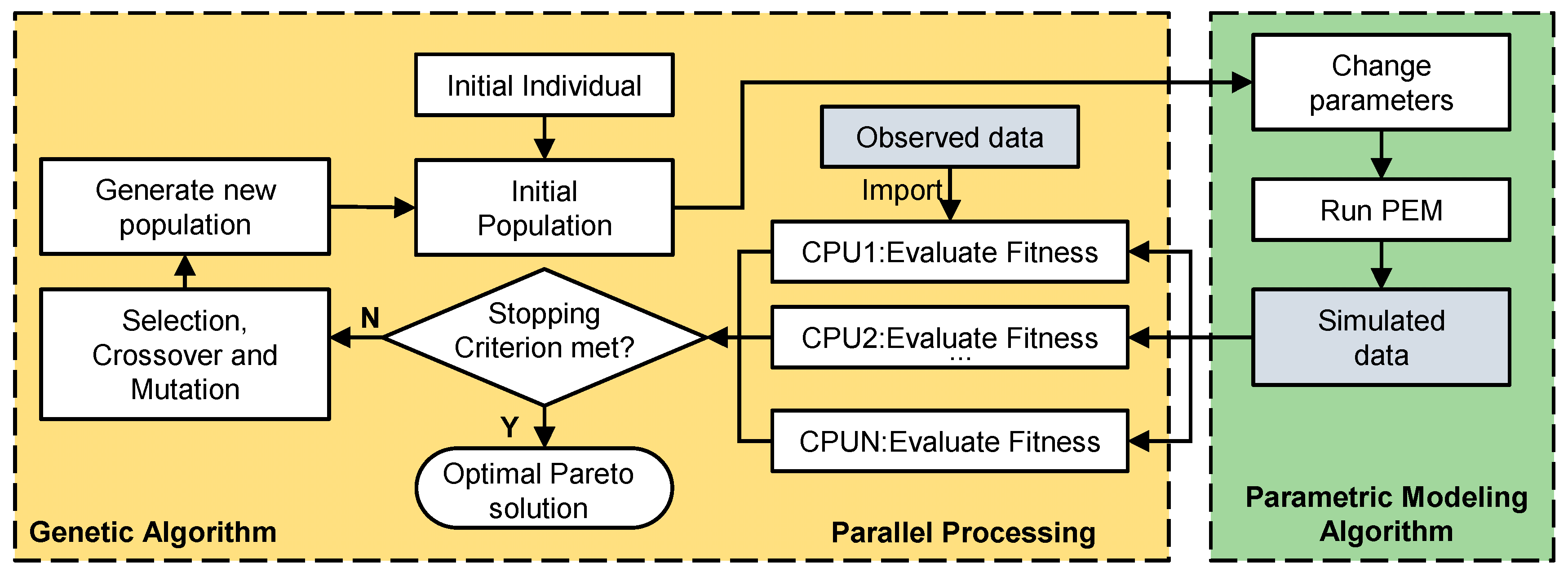
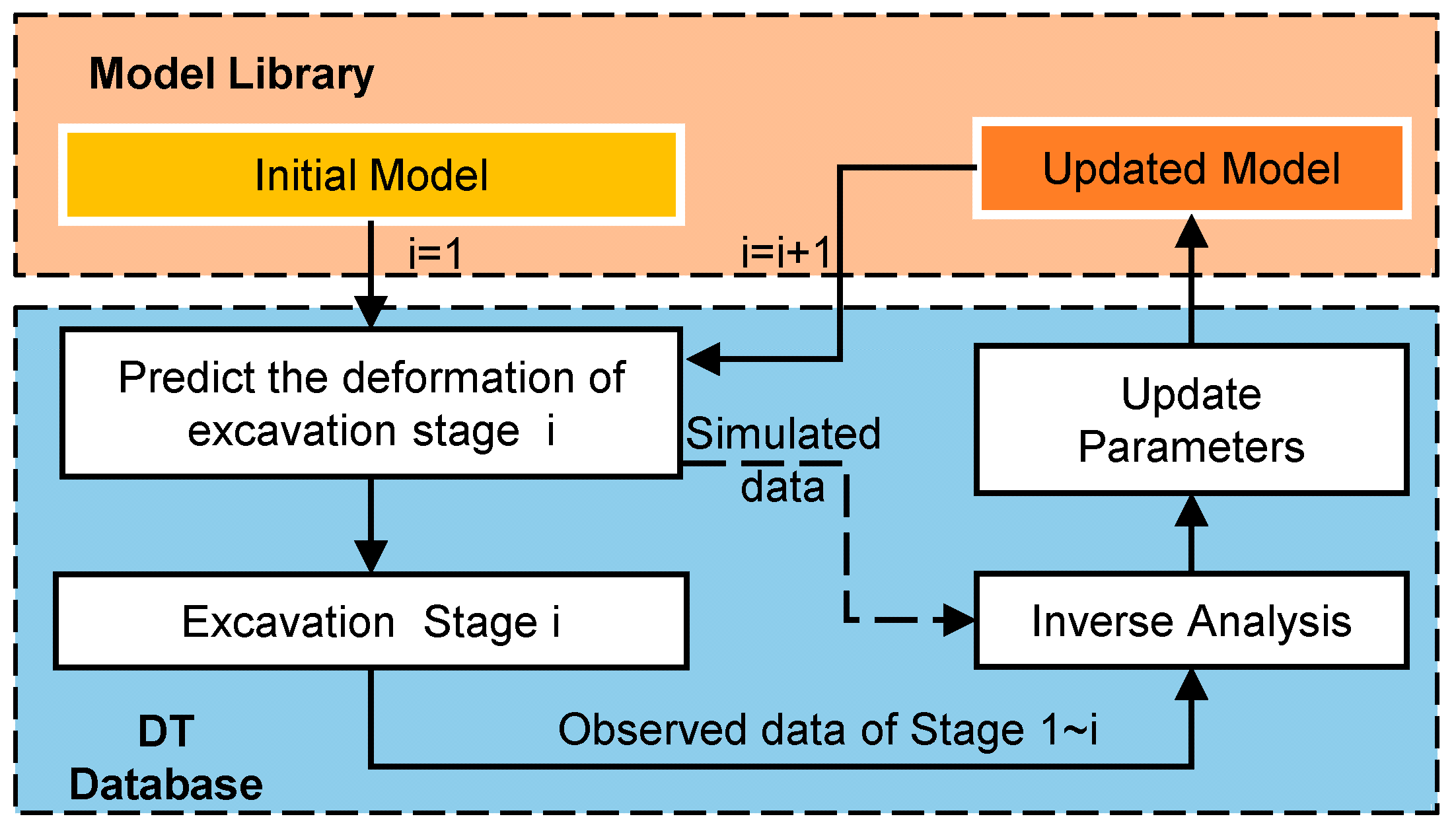
3.2. Inverse Analysis for Model Updating

A key feature of DT is its capability for automatic evolution. During the excavation of a foundation pit, geometric and mechanical characteristics undergo dynamic changes. The model parameters must be dynamically updated based on real-time and historical observed data to accurately predict pit deformation and ensure consistency between the numerical model and the physical object. This study developed a multi-parameter inverse analysis optimization algorithm based on genetic algorithms (GA), which automatically updates model parameters based on field monitoring deformation data.
GA are highly robust and adaptable, but their computational efficiency is low when dealing with large-scale and complex problems. Therefore, developing GA that can perform parallel computing is of great importance. Figure 7 illustrates the inverse analysis procedure based on the parallel GA proposed in this study.
Many studies have shown that wall deformation and ground movement are key factors affecting excavation performance [39,40,41]. In this study, the average difference in wall deformation between the simulated and observed data are represented by the least squares’ method. The error function F e r r is defined as follows:
F e r r = 1 N i = 1 N U i o U i s 2
where N is the number of measurement points, U i o is the value corresponding to the i th point of observed data and U i s is the value corresponding to the i th point of simulated data.
In inverse analysis, it is challenging to identify each soil parameter. Many studies have shown that optimizing E50ref as an inverse-analysis parameter is effective [15,42,43]. In inverse analysis, the soil modulus is treated as an individual, with each individual representing a point in the search space. A group of M j individuals represent the population of the jth generation. The initial population of these individuals serves as the parameter set for the parametric modeling program, which then produces numerical simulation results. These results are compared with the monitoring data to calculate the error function F e r r for the population. The objective of the inverse analysis is to minimize the value of F e r r . In genetic algorithms, the fitter the population, the higher its fitness. Therefore, the fitness function can be taken as the inverse of the error function:
f i t n e s s = 1 F e r r
In this study, parallel computing performs numerical analysis and fitness evaluation, significantly improving computational efficiency. When a population’s fitness is poor, the selection, crossover, and mutation processes generate new populations. These new populations, representing sets of new soil parameters, are then fed back into the parametric modeling program. This process is repeated until the convergence criteria are met. At this point, the Pareto solutions are output.
Parameters in the numerical model need to be updated automatically after the inverse analysis. Figure 8 illustrates the process of updating the model. Before the excavation, an initial model is quickly created based on the design parameters to predict the deformation caused by the first excavation of the foundation pit. If the predicted deformation is too large, a review of the support design is required. Then, after the first excavation, the displacement of the support structures and the soil is measured. The soil parameters are inverted based on the GA optimization algorithm, and the model is updated. The updated model then predicts the excavation deformation of the subsequent construction stage. If the predicted deformation is outside the specified range, preventative measures, such as adding temporary supports, must be taken to ensure the safety of the excavation. This process is repeated throughout excavation, with more observed data being added to the optimization objectives.
Meanwhile, each updated model is retained and added to the library of numerical models. More importantly, a large amount of data is integrated into the twin database. Prediction results from multiple models are used for on-site risk assessment and engineering decision-making. In addition, engineers can use extensive measurement data and soil parameters to optimize the future design of similar excavation projects.

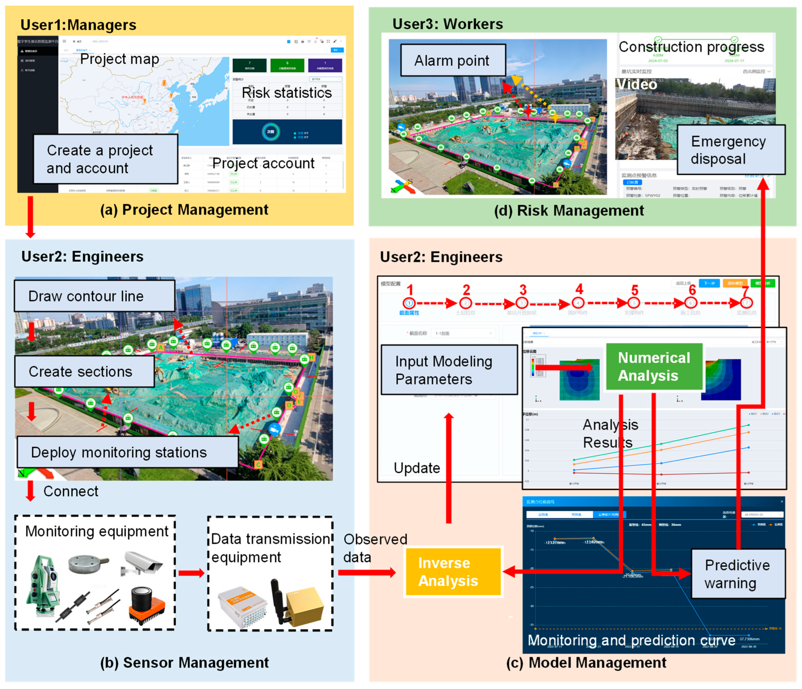
4. Prototype of Developed DT System

Figure 4 shows the overall architecture of the prototype system proposed in this study. It includes four functional modules: project management, sensor management, model management, and risk management. Figure 9 shows the prototype system application process. It is designed for managers, engineers, and workers. The following section will provide a detailed introduction to the system’s features.

4.1. Project Management

The system realizes multidimensional and multi-level excavation project management. Managers can manage multiple company projects in the system, comprehensively controlling the risk of excavation at the company level. Engineers can manage a foundation pit project in the system, enter project information, and conduct foundation pit early warning. Workers can view risk information and carry out risk disposal.

4.2. Sensor Management

Engineers can oversee the management of sensors and monitoring data within the system. The specifications of the support design drawings can delineate the pit’s contour and cross-section. According to the monitoring plan, the measurement points on the excavation pit plane must be arranged and associated with the cross-sections. The sensors comprise displacement and internal force sensors related to the measurement points. The model is built in sections containing measurement point information and associated sensors. Integrated with a router and 5G network, the data collection box transmits the field-observer data to the system in real-time. However, due to the hardware limitations of the equipment, deep displacement and internal force monitoring data must be uploaded manually.

4.3. Model Management

Modeling information is entered by engineers on the web page, including section properties, geometric information, mechanical parameters, construction progress, and other relevant data, to establish a 2D excavation pit model. This model then correlates with the on-site monitoring data, considering the temporal and spatial relationships between the two datasets. Finally, inverse analysis algorithms are employed to update the model automatically. The updated model is then used to generate predictions and warnings for further analysis.

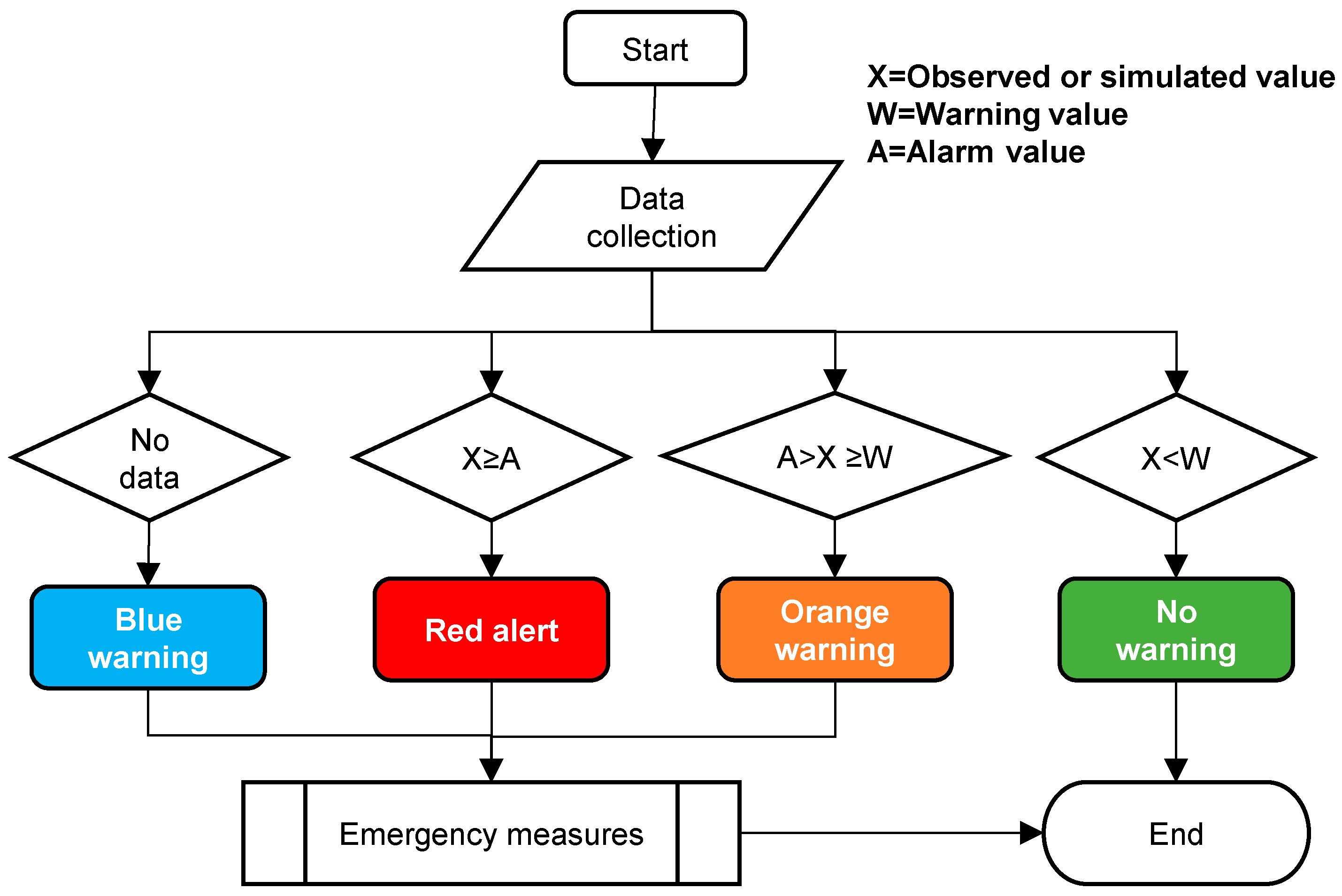
4.4. Risk Management

A three-stage early warning mechanism has been incorporated into the system. The early warning workflow is illustrated in Figure 10. The system can compare the observed and simulated data with the specified limits while simultaneously providing both real-time and predictive warnings. This system’s predictive warning of future construction steps is a significant advantage compared to other systems. The alarm point will display a flashing orange or red light on the plan to alert managers of hazardous locations, which facilitates the workers’ prompt implementation of appropriate safety measures.

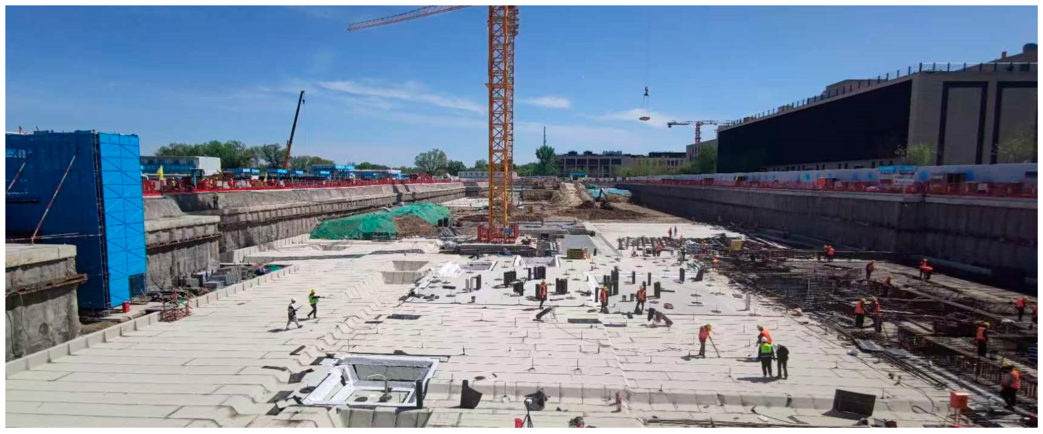
5. Case Study: A Foundation Pit Excavation Project in Beijing

To verify the effectiveness of the monitoring system proposed in the previous section, the author chose a pit excavation project in Beijing as a case study to demonstrate its application. Figure 11 depicts the excavation construction site. Using the proposed DT modeling architecture, the excavation’s field monitoring data were collected, a virtual model of the excavation was established, and the model parameters were updated based on the monitoring data. The updated model more accurately predicts excavation deformation, thus ensuring safety at every stage of construction on site.

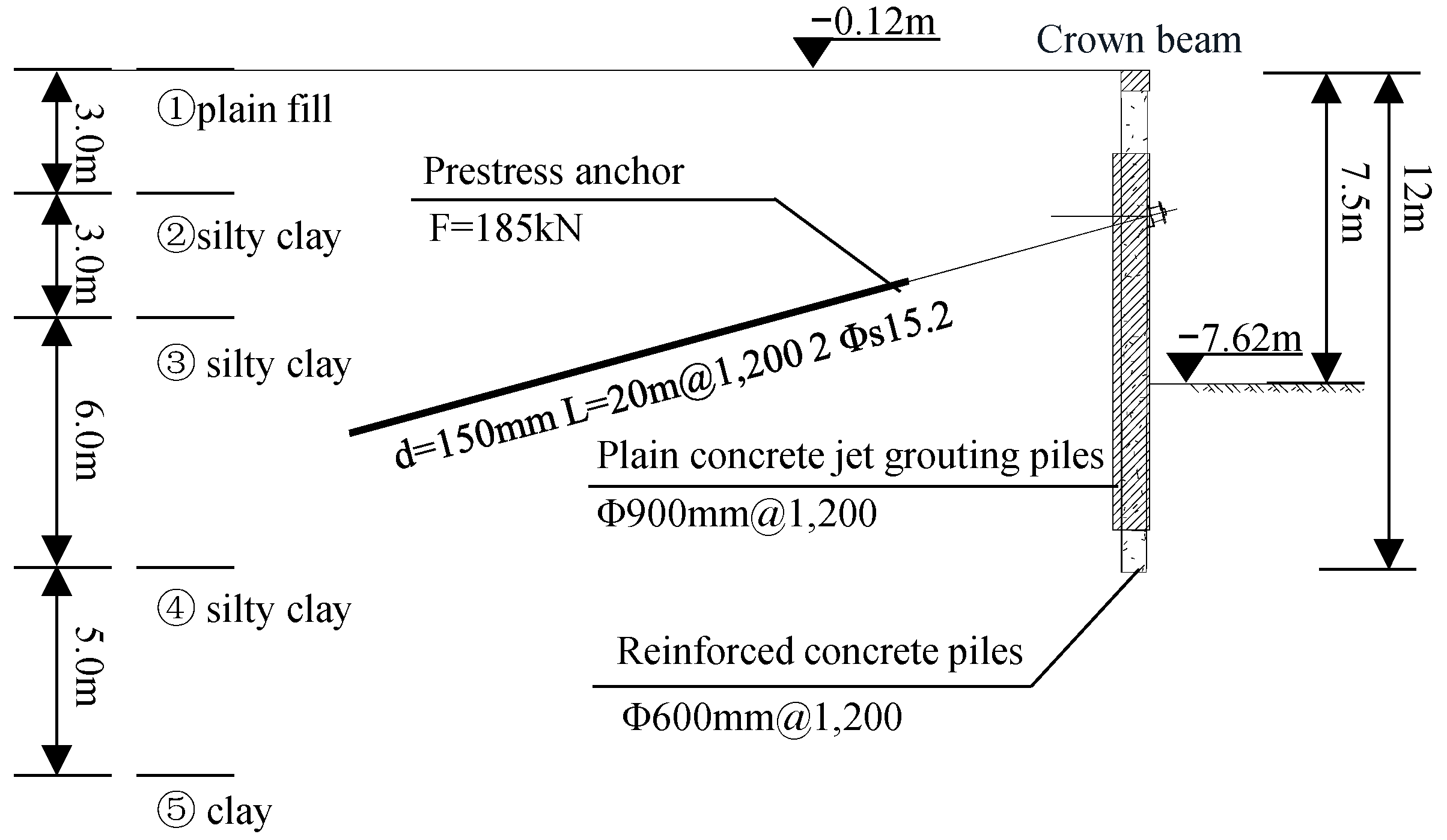
5.1. Project Overview

The foundation pit of this project measures 178.60 m in length and 69.80 m in width, with an excavation depth ranging from 4.0 to 7.50 m. The excavation plan is illustrated in Figure 12. Considering the depth of the excavation and the surrounding environment, the pit primarily employs a bored pile + anchor support. The J–K sectional view is shown in Figure 13. The eastern side of the excavation pit exhibits a relatively shallow depth, with the H–I employing a cantilever pile support.

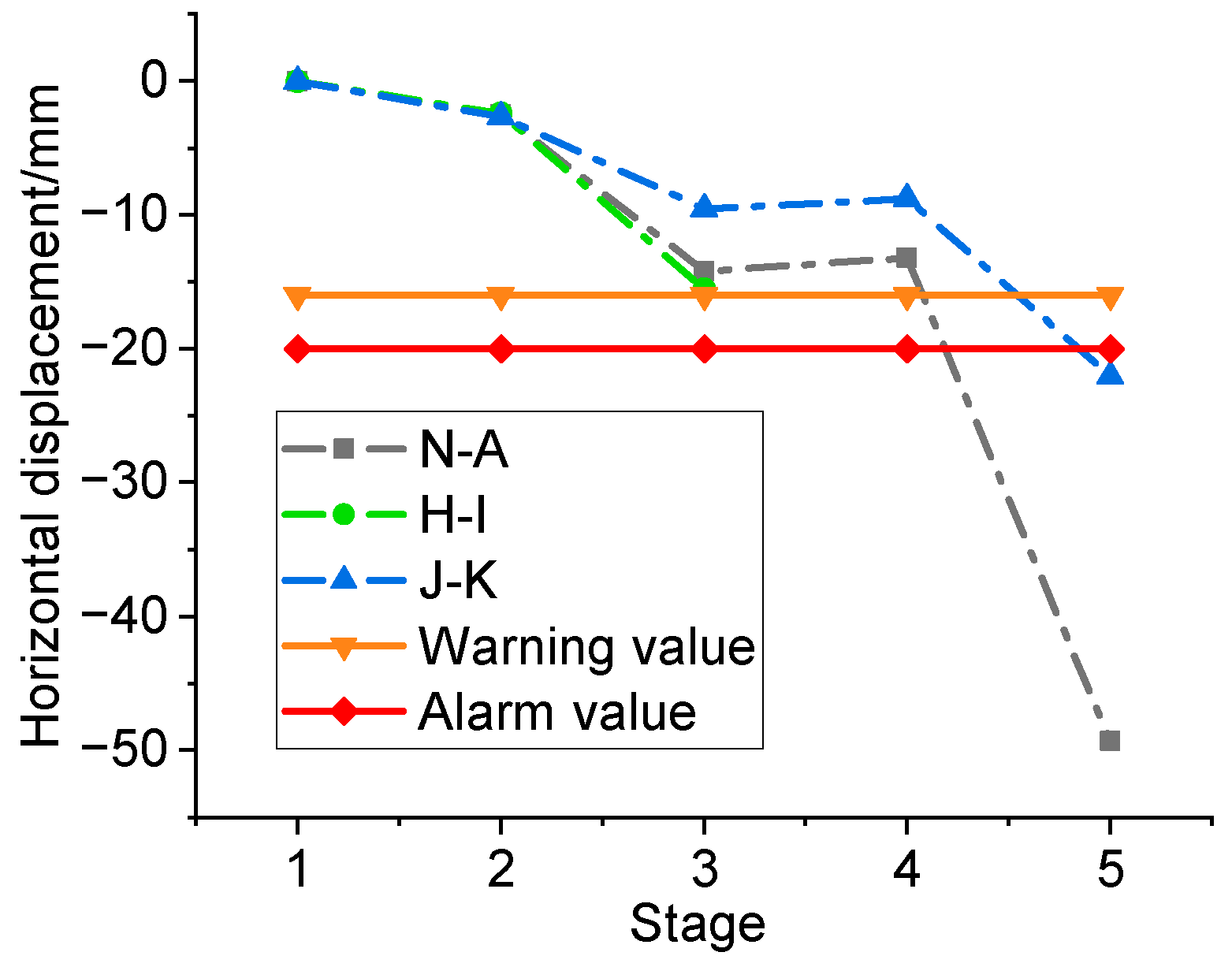
5.2. Collecting Data from Physical Spaces

During the construction of the excavation, a range of sensory devices are employed to collect real-time data on the site, primarily comprising monitoring data and data about the construction process. The layout of the monitoring points is illustrated in Figure 12. The primary displacement monitoring contents include pile top displacement, lateral deflection, and ground settlement. Taking the pile top displacement as an example. It is gauged using an automated total station, as shown in Figure 14. The monitoring accuracy is extremely high, with an error not exceeding 0.3 mm. The internal forces of the anchor cables are also monitored and uploaded to the system. The accumulated data are automatically transmitted to the DT monitoring system via a 5G base station. The installation of surveillance cameras at the construction site serves two principal purposes: firstly, to monitor the progress of the construction in real-time, and secondly, to identify any safety hazards promptly.
For example, the main construction schedule for J–K is shown in Table 1. Each excavation is about 2 to 3 m deep. The engineers were responsible for recording the construction date after each key construction stage. Afterwards, inverse analyses were performed based on the monitored data to update the finite element model for further prediction.

5.3. Modeling in the Virtual Space

The most crucial step in DT is modeling in virtual space. This study uses the parametric modeling algorithm to establish a finite element model of the deep foundation pit in ABAQUS. During the excavation process, inverse analysis algorithms update the model parameters.
(1)
Modeling and initial analysis
Take the J–K section as an example. The depth of excavation of the J–K section of the pit is 7.5 m. In this model, the soil is assumed to have dimensions of 30 m × 50 m. The mesh size of the soil to be analyzed is set at 0.5 m. The number of elements is 12,223. The GM of the excavation pit can be rapidly constructed, as demonstrated in Figure 15.
The soil is modeled using plane strain elements. Table 2 shows the input parameters for the five clay layers. In this analysis, the MHS model is employed, which necessitates the specification of a series of soil stiffness parameters, including the reference secant Young’s modulus at the 50% stress level, Eoedref, the reference oedometer tangent modulus, E50ref, and the reference unloading modulus, Eurref. The stiffness parameters correspond to the reference pressure, pref, usually set equal to 100 stress units, and m is the power for the stress-level dependency of stiffness. Obtaining these parameters through laboratory tests is a time-consuming and costly process. The exploration report for this project provides only the compression modulus, Es1~2. In accordance with the recommendations set forth in engineering manuals and the related literature, the author initially assumes that E50ref = Eoedref, Eurref = 3E50ref, Es1~2 = Eoedref. Subsequently, these parameters are updated through inverse analysis. The effective cohesion, c’, effective internal friction angle, φ’, and unit weight, γ, of the soil can be obtained from the geological exploration report. The dilatancy angle, Ψ, depends on the volume change characteristics of the soil and is equal to zero for normally consolidated clays. The remaining MHS model parameters, the at-rest earth pressure coefficient, K0, and Poisson’s ratio, νur, are taken as recommended values from engineering manuals.
Piles are modeled using plane strain elements, and anchor cables are represented by line elements. The anchor cables are modeled with truss sections. One end is embedded in the pile, and the other end is embedded in the soil. The pre-stressing of the anchor rods is applied using the method of temperature reduction. The materials for the supporting structure, which include concrete (C30) and steel strands (S1860), are both modeled with linear elastic constitutive relationships. The parameters can be obtained from the specification database. By inputting the mechanical parameters of the soil and the supporting structure, the PM can be quickly established.
Based on the construction plan delineated in Table 1, the input of construction data enables establishing a finite element model that simulates the entire excavation process. Before the commencement of construction, a preliminary risk analysis is undertaken to predict potential construction risks. The horizontal displacement of each stage, as illustrated in Figure 16, indicates that the maximum deformation occurs at the top of the supporting piles. The system can automatically extract the displacement of the measuring points, which can then be used to evaluate the risk of excavation. Currently, the system does not support the output of internal forces in the supporting structure, and further improvements need to be made in future research.
Figure 17 presents the horizontal displacement of the piles on top of each section. As shown in Figure 17, the initial predicted value of stage 5 exceeded the warning limit, and the system should have issued a prediction warning. Based on engineering experience, the analysis results were considered conservative and inaccurate, and the models needed to be updated based on the measured data once the excavation was carried out.
During the foundation pit excavation, an automated total station monitored the deformation of the pile top. Some monitoring points (including V21, V27, and V33) were selected to analyze the deformation pattern of horizontal displacement of the pile top in each section. Monitoring data are lacking for Stage 1, the piling phase, due to the absence of monitoring points. After construction, the top deformation was minimal, leading us to assume a measured value of zero for stage 1. As shown in Figure 18, the horizontal displacements at all stages did not exceed the specified limits. Compared with Figure 18, it is clear that the model used in the preliminary analysis is inaccurate and needs to be updated.
(2)
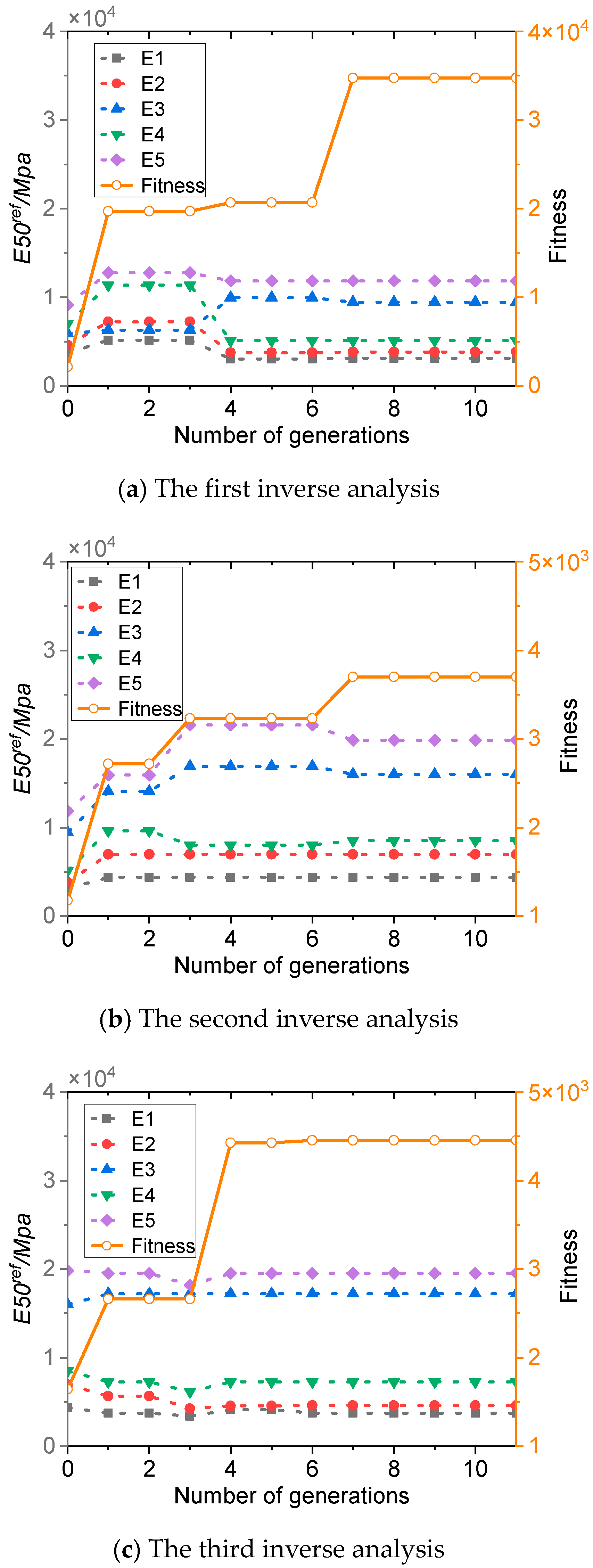
Inverse analysis and model updating
Taking the J–K section as an example, the horizontal displacement at measuring point V27 was employed as the target value, with engineers utilizing a dynamic updating process, as illustrated in Figure 8, to ensure the model reflects the most up-to-date data.
The elastic modulus (E50ref) of the five soil layers was employed as the parameter for inverse analysis. The first inverse analysis employed the measured horizontal displacement at stage 2 as the target value. The second inverse analysis utilized the measured horizontal displacement at stage 2 and stage 3 as the target values. Finally, the third inverse analysis employed the measured horizontal displacement at stage 2, stage 3, and stage 4 as the target value. The initial parameters were adopted from the geological survey report. After each inverse analysis, the models were updated with the optimal parameter solution. Figure 19 illustrates the trends of soil parameters and fitness during the three iterations of inverse analysis. It shows that as the number of generations increases, the soil parameters of each layer gradually converge, and the fitness continuously improves. The calculation demonstrates convergence after approximately seven generations, suggesting that the algorithm possesses effective convergence capabilities.
(3)
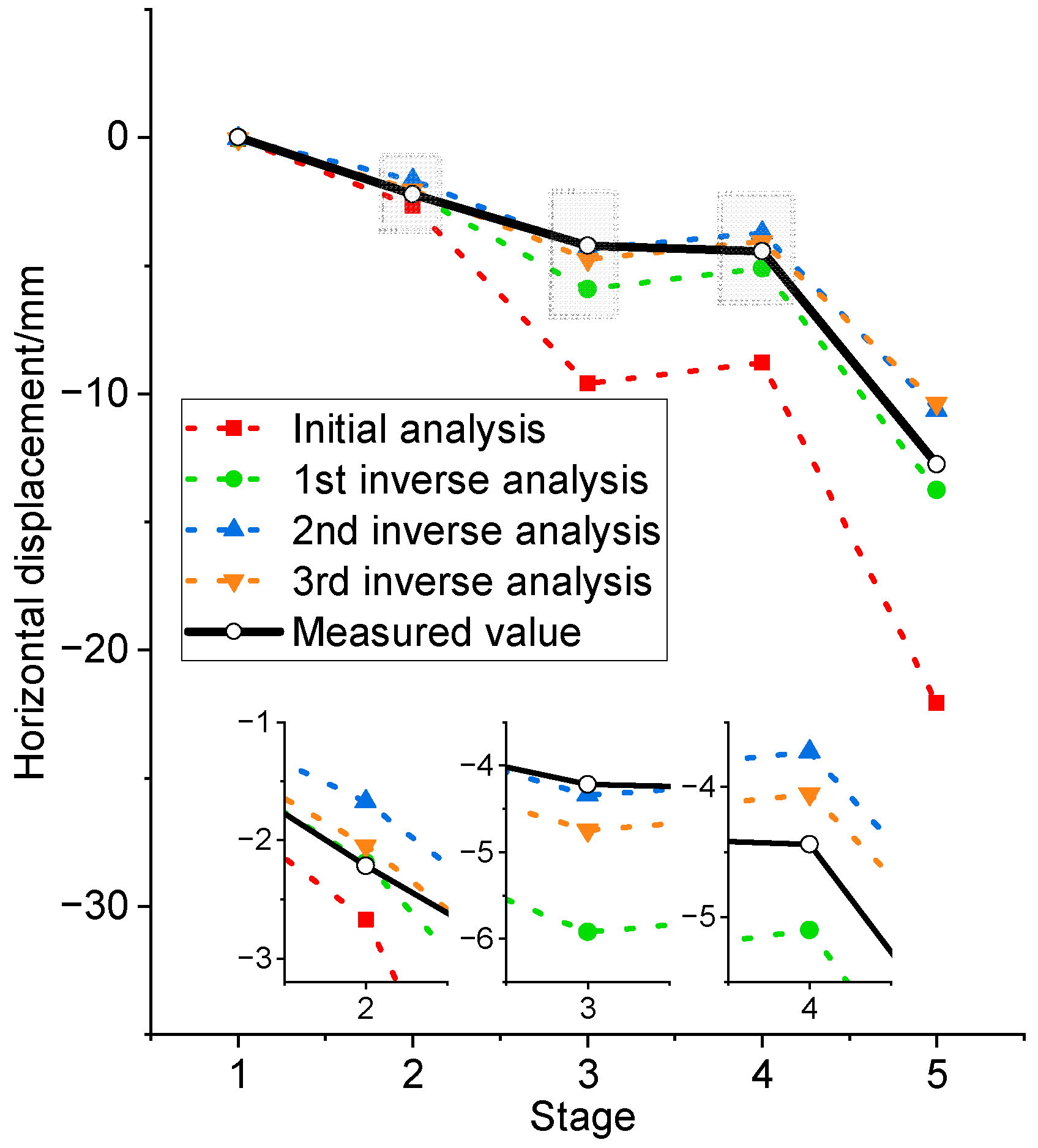
Prediction with the updated model
The initial analysis indicated a significant error between the predicted and measured horizontal displacement values at the pile top. As shown in Figure 20, as the excavation depth increases, this error also gradually increases. The maximum error reached 40.3 mm, far exceeding the limit allowed by the engineering project. The reason is that significant changes occurred in the soil parameters during the excavation process. It is difficult to accurately predict the deformation of the foundation pit using the original geological exploration parameters. Therefore, it is very necessary to dynamically update the model parameters through inverse analysis. After three iterations of back analysis, the error between the predicted and measured values continuously decreased. As shown in Figure 20b, the maximum value of the mean error decreases from 12.46 to 1.32 mm, meeting the precision requirements for engineering applications. Figure 20b demonstrates that the model’s predictive capability continuously enhances as the inverse analysis progresses.
Taking V27 as an example, Figure 21 illustrates the predictive outcomes following three iterations of the inversion process within the model during the excavation. It demonstrates that the predicted values converge towards the measured values as the model undergoes continual updates.
During the construction process, we focus on the error between the predicted values and the measured values for the current construction step. When the error is less than 10%, we consider the model’s predictions to be reliable. Table 3 shows the statistics of the percentage error between the predicted and measured values of the horizontal displacement of V27 for each construction stage. The following can be seen from the table:
(1)
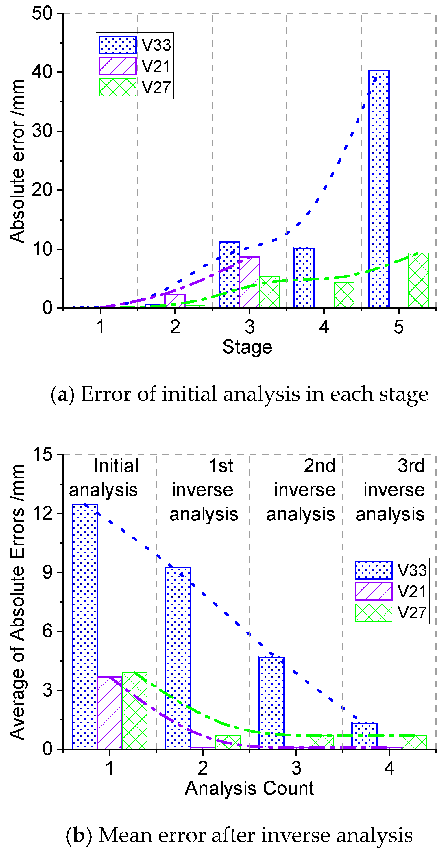
In stage 2, the first inverse analysis was carried out after 2 m of excavation. The prediction error for stage 2 was approximately 20% for the initial model and 1% for the updated model, which indicates that the updated model is closer to the actual site. The prediction error of the updated model for the deformation in stage 3 is about 40%.
(2)
In stage 3, after the second update, the model’s prediction error for stage 3 was less than 1%, and for stage 4, it was approximately 16%.
(3)
In stage 4, the model was updated for the third time. The updated model predicted the deformation of the final construction stage with an error of about 19%, which was slightly larger than the first and second updates.
In summary, the updated model provides more accurate predictions for the current construction stages. It shows that the twin model is closer to the actual state of the project. The mapping of the virtual model and physical entities to each other was achieved. In addition, the results of the multi-model analysis show that the predictions derived from DTFPM show higher accuracy. It meets the requirements for engineering use.

6. Conclusions and Future Work

This study applies DT technology to foundation pit engineering and develops an intelligent monitoring system. The system uses automated monitoring equipment and 5G transmission technology to obtain monitoring data from the site. More importantly, the system integrates a DTFPM to predict and manage safety risks during excavation. A parametric modeling algorithm is used to drive the rapid establishment of the model. Furthermore, an inverse analysis optimization algorithm based on GA is used for real-time model updates. The updated model, which is closer to the physical entity, is used to assess the risks of foundation pit excavation and guide on-site construction. The conclusions of this study are as follows:
(1)
A DT-based modeling and application framework for foundation pits is proposed. The comprehensive framework, which includes the physical space, finite element model, digital twin data, intelligent early warning web services, and their connections, has the potential to significantly enhance the safety monitoring and management of excavation in the construction industry. Additionally, a safety risk management scheme for foundation pit construction based on DTFPM is also proposed, which could promote the application of digital twin technology in construction safety monitoring, thereby improving overall safety standards.
(2)
The authors summarize the five basic support types and refines the key modeling parameters for each support type. A method for generating simulation models based on ABAQUS is formed by sorting out the relationships between different parameters. A parametric modeling algorithm based on ABAQUS is developed. This algorithm supports various types of support and uses multiple soil constitutive models, such as M-C and MHS, which are suitable for numerical simulations under complex geological conditions. This method can generate a FEM within one second, reducing the difficulty of modeling foundation pits and allowing numerical simulations to be used in more engineering applications.
(3)
This study focuses on the deformation of the support structures and the changes in soil elastic modulus during the excavation of foundation pits. A parallel computing-based inverse analysis algorithm using GA is developed. Analysis shows that the algorithm has high computational efficiency and strong convergence, able to converge to the optimal solution within 10 generations. It enables real-time updating of model parameters based on field monitoring deformation data, which enhances DTFPM’s predictive capabilities and ensures accurate predictions. Case analysis shows that the prediction error of the updated model for the current construction stage can be reduced to within 10%. The average error was reduced from 12.46 mm to 1.32 mm after model updating. Additionally, the algorithm supports multi-task parallel computing, exhibiting excellent analysis efficiency and convergence.
(4)
An intelligent safety early warning system based on DTFPM is established, and its practicality is validated in engineering practice. Intelligent sensing devices were employed for the collection and transmission of monitoring data. The author developed multiple data interfaces and a relational database, facilitating the establishment and updating of the DTFPM model with multi-source and heterogeneous data. A three-stage early warning mechanism is integrated into the system, offering advanced warning services for the risks of foundation pit excavation. This system ensures construction safety by providing timely and accurate warnings.
This study validates the effectiveness and feasibility of DTFPM through a real-project application. It can be applied to large-scale underground projects, guiding the modeling and updating of foundation pits, data perception, risk prediction, and safety management during excavation. However, the proposed method still has some limitations. Integrating such a large amount of field information is challenging. Data perception and transmission capabilities need to be further enhanced. And the impact of observation errors on model updates needs to be explored.

Author Contributions

Conceptualization, P.P.; Methodology, P.P.; Software, J.-X.F.; Formal analysis, S.-H.S.; Investigation, J.-X.F.; Resources, P.P.; Data curation, J.-T.W.; Writing—original draft, S.-H.S.; Writing—review & editing, J.-R.L.; Visualization, J.-R.L.; Supervision, H.-S.W.; Project administration, H.-S.W.; Funding acquisition, J.-T.W. All authors have read and agreed to the published version of the manuscript.

Funding

This research was supported by the National Key R&D Program of China (Project No. 2023YFC3805800). This research was also supported by the project “Constructing a theoretical system for sustainable development strategy of construction enterprises with digital platforms as the core”, which was funded by CHINA CONSTRUCTION THIRD ENGINEERING BUREAU BEIJING CO., LTD. The authors also acknowledge the support from Tsinghua University-China Construction Third Engineering Bureau Group Co., Ltd. Joint Research Center for New Technology in Civil Engineering.

Data Availability Statement

The original contributions presented in the study are included in the article, further inquiries can be directed to the corresponding author.

Conflicts of Interest

The authors declare no conflict of interest.

References

  1. Zheng, G.; Zhu, H.; Liu, X.; Yang, G. Control of safety of deep excavations and underground engineering and its impact on surrounding environment. China Civ. Eng. J. 2016, 49, 1–24. [Google Scholar]
  2. Qian, Q. Challenges faced by underground projects construction safety and countermeasures. Chin. J. Rock Mech. Eng. 2012, 31, 1945–1956. [Google Scholar]
  3. Gong, X.N.; Zhang, X.C. Excavation collapse of Hangzhou subway station in soft clay and numerical investigation based on orthogonal experiment method. J. Zhejiang Univ.-Sci. A 2012, 13, 760–767. [Google Scholar] [CrossRef]
  4. Hsieh, P.G.; Ou, C.Y.; Lin, Y.L. Three-dimensional numerical analysis of deep excavations with cross walls. Acta Geotech. 2013, 8, 33–48. [Google Scholar] [CrossRef]
  5. Shi, J.W.; Ng, C.W.W.; Chen, Y.H. Three-dimensional numerical parametric study of the influence of basement excavation on existing tunnel. Comput. Geotech. 2015, 63, 146–158. [Google Scholar] [CrossRef]
  6. Guo, P.P.; Gong, X.N.; Wang, Y.X. Displacement and force analyses of braced structure of deep excavation considering unsymmetrical surcharge effect. Comput. Geotech. 2019, 113, 103102. [Google Scholar] [CrossRef]
  7. Ye, S.H.; Zhao, Z.F.; Wang, D.Q. Deformation analysis and safety assessment of existing metro tunnels affected by excavation of a foundation pit. Undergr. Space 2021, 6, 421–431. [Google Scholar] [CrossRef]
  8. Tarantola, A.; Valette, B. Generalized non-linear inverse problems solved using the least-squares criterion. Rev. Geophys. 1982, 20, 219–232. [Google Scholar] [CrossRef]
  9. Jin, Y.F.; Yin, Z.Y.; Zhou, W.H.; Huang, H.W. Multi-objective optimization-based updating of predictions during excavation. Eng. Appl. Artif. Intell. 2019, 78, 102–123. [Google Scholar] [CrossRef]
  10. Tao, Y.Q.; He, W.; Sun, H.L.; Cai, Y.Q.; Chen, J.Q. Multi-objective optimization-based prediction of excavation-induced tunnel displacement. Undergr. Space 2022, 7, 735–747. [Google Scholar] [CrossRef]
  11. Kim, S.; Finno, R.J. Inverse Analysis of a Supported Excavation in Chicago. J. Geotech. Geoenvironmental Eng. 2019, 145, 4019050. [Google Scholar] [CrossRef]
  12. Liu, C.Y.; Wang, Y.; Hu, X.M.; Han, Y.L.; Zhang, X.P.; Du, L.Z. Application of GA-BP Neural Network Optimized by Grey Verhulst Model around Settlement Prediction of Foundation Pit. Geofluids 2021, 2021, 5595277. [Google Scholar] [CrossRef]
  13. Sampson, J.R. Adaptation in Natural and Artificial Systems (John H. Holland); SIAM Review: Philadelphia, PA, USA, 1976; Volume 18, pp. 529–530. [Google Scholar]
  14. Levasseur, S.; Malecot, Y.; Boulon, M.; Flavigny, E. Statistical inverse analysis based on genetic algorithm and principal component analysis: Applications to excavation problems and pressuremeter tests. Int. J. Numer. Anal. Methods Geomech. 2010, 34, 471–491. [Google Scholar] [CrossRef]
  15. Hashash, Y.M.A.; Levasseur, S.; Osouli, A.; Finno, R.; Malecot, Y. Comparison of two inverse analysis techniques for learning deep excavation response. Comput. Geotech. 2010, 37, 323–333. [Google Scholar] [CrossRef]
  16. Yin, Z.Y.; Jin, Y.F.; Shen, J.S.; Hicher, P.Y. Optimization techniques for identifying soil parameters in geotechnical engineering: Comparative study and enhancement. Int. J. Numer. Anal. Methods Geomech. 2018, 42, 70–94. [Google Scholar] [CrossRef]
  17. Li, X.; Liu, X.; Li, C.Z.; Hu, Z.M.; Shen, G.Q.; Huang, Z.Y. Foundation pit displacement monitoring and prediction using least squares support vector machines based on multi-point measurement. Struct. Health Monit.-Int. J. 2019, 18, 715–724. [Google Scholar] [CrossRef]
  18. Zhang, C.; Li, J.Z.; He, Y. Application of optimized grey discrete Verhulst-BP neural network model in settlement prediction of foundation pit. Environ. Earth Sci. 2019, 78, 441. [Google Scholar] [CrossRef]
  19. Zhou, Y.; Li, S.Q.; Zhou, C.; Luo, H.B. Intelligent Approach Based on Random Forest for Safety Risk Prediction of Deep Foundation Pit in Subway Stations. J. Comput. Civ. Eng. 2019, 33, 5018004. [Google Scholar] [CrossRef]
  20. Zhao, Y.R.; Chen, X.S.; Hu, B.; Huang, L.P.; Lu, G.H.; Yao, H.L. Automatic monitoring and control of excavation disturbance of an ultra-deep foundation pit extremely adjacent to metro tunnels. Tunn. Undergr. Space Technol. 2023, 142, 105445. [Google Scholar] [CrossRef]
  21. Su, Y.Y.; Hashash, Y.M.A.; Liu, L.Y. Integration of construction as-built data via laser scanning with geotechnical monitoring of urban excavation. J. Constr. Eng. Manag. 2006, 132, 1234–1241. [Google Scholar] [CrossRef]
  22. Zhu, C.; Yan, Z.; Lin, Y.; Xiong, F.; Tao, Z. Design and Application of a Monitoring System for a Deep Railway Foundation Pit Project. IEEE Access 2019, 7, 107591–107601. [Google Scholar] [CrossRef]
  23. Hong, C.; Zhang, J.; Chen, W. An Integrated Intelligent Approach for Monitoring and Management of a Deep Foundation Pit in a Subway Station. Sensors 2022, 22, 8737. [Google Scholar] [CrossRef] [PubMed]
  24. Opoku, D.J.; Perera, S.; Osei-Kyei, R.; Rashidi, M. Digital twin application in the construction industry: A literature review. J. Build. Eng. 2021, 40, 102726. [Google Scholar] [CrossRef]
  25. Lin, J.R.; Zhang, J.P.; Zhang, X.Y.; Hu, Z.Z. Automating closed-loop structural safety management for bridge construction through multisource data integration. Adv. Eng. Softw. 2019, 128, 152–168. [Google Scholar] [CrossRef]
  26. Zhang, Y.Y.; Kang, K.; Lin, J.R.; Zhang, J.P.; Zhang, Y. Building information modeling-based cyber-physical platform for building performance monitoring. Int. J. Distrib. Sens. Netw. 2020, 16, 1550147720908170. [Google Scholar] [CrossRef]
  27. Shafto, M.; Conroy, M.; Doyle, R.; Glaessgen, E.; Kemp, C.; LeMoigne, J.; Wang, L. DREFT Modeling, Simulation, Information Technology and Processing Roadmap Technology Area 11; National Aeronautics and Space Administration: Washington, DC, USA, 2010.
  28. Grieves, M.; Vickers, J. Digital Twin: Mitigating Unpredictable, Undesirable Emergent Behavior in Complex Systems. In Transdisciplinary Perspectives on Complex Systems; Springer International Publishing: Cham, Switzerland, 2017; pp. 85–113. [Google Scholar]
  29. Tao, F.; Zhan, H.; Liu, A.; Nee, A.Y.C. Digital Twin in Industry: State-of-the-Art. Ieee Trans. Ind. Inform. 2019, 15, 2405–2415. [Google Scholar] [CrossRef]
  30. Callcut, M.; Agliozzo, J.P.C.; Varga, L.; McMillan, L. Digital Twins in Civil Infrastructure Systems. Sustainability 2021, 13, 11549. [Google Scholar] [CrossRef]
  31. Liu, X.; Sun, H.; Lin, J. Digital Selves Based Intelligent Construction Framework. Int. J. Crowd Sci. 2024, 8, 184–194. [Google Scholar] [CrossRef]
  32. Zheng, Z.; Liao, W.J.; Lin, J.R.; Zhou, Y.C.; Zhang, C.; Lu, X.Z. Digital Twin-Based Investigation of a Building Collapse Accident. Adv. Civ. Eng. 2022, 2022, 9568967. [Google Scholar] [CrossRef]
  33. Lin, J.R.; Wu, D.P. An approach to twinning and mining collaborative network of construction projects. Autom. Constr. 2021, 125, 103643. [Google Scholar] [CrossRef]
  34. Lin, C.; Hu, Z.Z.; Yang, C.; Deng, Y.C.; Zheng, W.; Lin, J.R. Maturity Assessment of Intelligent Construction Management. Buildings 2022, 12, 1742. [Google Scholar] [CrossRef]
  35. Jiang, C.; Li, X.; Lin, J.R.; Liu, M.; Ma, Z.L. Adaptive control of resource flow to optimize construction work and cash flow via online deep reinforcement learning. Autom. Constr. 2023, 150, 104817. [Google Scholar] [CrossRef]
  36. Jiang, F.; Ma, L.; Broyd, T.; Chen, K. Digital twin and its implementations in the civil engineering sector. Autom. Constr. 2021, 130, 103838. [Google Scholar] [CrossRef]
  37. Ye, Z.J.; Ye, Y.; Zhang, C.P.; Zhang, Z.M.; Li, W.; Wang, X.J.; Wang, L.; Wang, L.B. A digital twin approach for tunnel construction safety early warning and management. Comput. Ind. 2023, 144, 103783. [Google Scholar] [CrossRef]
  38. Sun, Z.; Li, H.; Bao, Y.; Meng, X.; Zhang, D. Intelligent Risk Prognosis and Control of Foundation Pit Excavation Based on Digital Twin. Buildings 2023, 13, 247. [Google Scholar] [CrossRef]
  39. Hsieh, P.G.; Ou, C.Y. Shape of ground surface settlement profiles caused by excavation. Can. Geotech. J. 1998, 35, 1004–1017. [Google Scholar] [CrossRef]
  40. Wang, J.H.; Xu, Z.H.; Wang, W.D. Wall and Ground Movements due to Deep Excavations in Shanghai Soft Soils. J. Geotech. Geoenvironmental Eng. 2010, 136, 985–994. [Google Scholar] [CrossRef]
  41. Schuster, M.; Kung, G.T.C.; Juang, C.H.; Hashash, Y.M.A. Simplified Model for Evaluating Damage Potential of Buildings Adjacent to a Braced Excavation. J. Geotech. Geoenvironmental Eng. 2009, 135, 1823–1835. [Google Scholar] [CrossRef]
  42. Calvello, M.; Finno, R.J. Selecting parameters to optimize in model calibration by inverse analysis. Comput. Geotech. 2004, 31, 411–425. [Google Scholar] [CrossRef]
  43. Finno, R.J.; Calvello, M. Supported excavations: Observational method and inverse modeling. J. Geotech. Geoenvironmental Eng. 2005, 131, 826–836. [Google Scholar] [CrossRef]
Figure 1. DT framework for deep foundation pits modeling.
Buildings 15 00366 g001
Figure 2. Multi-source information collection and transmission.
Buildings 15 00366 g002
Figure 3. Deep foundation pit numerical modeling and updating architecture based on DT.
Buildings 15 00366 g003
Figure 4. Intelligent monitoring system architecture.
Buildings 15 00366 g004
Figure 5. Relational database of system.
Buildings 15 00366 g005
Figure 6. Schematic of the parametric modeling algorithm.
Buildings 15 00366 g006
Figure 7. Procedure of parallel GA-based inverse analysis.
Buildings 15 00366 g007
Figure 8. Model update procedure.
Buildings 15 00366 g008
Figure 9. The prototype system application process: (a) project management; (b) sensor management; (c) model management; (d) risk management.
Buildings 15 00366 g009
Figure 10. Three-stage early warning mechanism.
Buildings 15 00366 g010
Figure 11. The excavation construction site of the project.
Buildings 15 00366 g011
Figure 12. Layout of the monitoring points.
Buildings 15 00366 g012
Figure 13. Sectional view of J–K.
Buildings 15 00366 g013
Figure 14. Automated total station and measurement target.
Buildings 15 00366 g014
Figure 15. Geometric model.
Buildings 15 00366 g015
Figure 16. Predicted horizontal displacement of J–K.
Buildings 15 00366 g016
Figure 17. Horizontal displacement predicted by the initial model.
Buildings 15 00366 g017
Figure 18. Measured horizontal displacement.
Buildings 15 00366 g018
Figure 19. Evolutions of the soil parameter and the objective function fitness.
Buildings 15 00366 g019
Figure 20. The error between the predicted and measured horizontal displacement.
Buildings 15 00366 g020
Figure 21. Horizontal displacement predicted by the updated model.
Buildings 15 00366 g021
Table 1. Construction progress.
Stage No.Stage NameExcavation Activities
1Add1Piles construction
2Remove1Excavated to −2.12 m
3Remove2Excavated to −4.12 m
4Add2Anchor construction
5Remove3Excavated to the bottom
Table 2. The soil mechanical parameters.
Soil
Layer
Depth
(m)
γ
(kN/m3)
E50ref
(MPa)
Eoedref
(MPa)
Eurref
(MPa)
c′
(kPa)
ϕ′
(°)
K0
10~319.83700370011,1001480.72
23~620.04600460013,80022300.13
36~1219.85900590017,70037110.63
412~1720.17000700021,00032120.59
517~3018.69100910027,30035120.59
Notes: pref = 100; m = 0.5; νur = 0.2; Ψ = 0; values not changed.
Table 3. The percentage error between the predicted and measured values.
AnalysisMeasured ValueInitial
Analysis
1st Inverse Analysis2nd Inverse
Analysis
3rd Inverse Analysis
Stage No.
Stage10N/AN/AN/AN/A
Stage2−2.22−20%−1%−25%−8%
Stage3−4.22−127%−40%−3%−13%
Stage4−4.44−98%−15%−16%−9%
Stage5−12.75−73%−8%−17%−19%
Disclaimer/Publisher’s Note: The statements, opinions and data contained in all publications are solely those of the individual author(s) and contributor(s) and not of MDPI and/or the editor(s). MDPI and/or the editor(s) disclaim responsibility for any injury to people or property resulting from any ideas, methods, instructions or products referred to in the content.

