Abstract
A comprehensive compaction technology combining layered compaction by vibratory rollers and interlayer heavy tamping is proposed and applied to an embankment project to improve the compaction effects of high loess embankments. The compression characteristics of the highly compacted soil layers after re-tamping are investigated through soil mechanics tests and onsite settlement monitoring. The results of the soil mechanics tests show that the working mechanism of heavy tamping is a re-compacting effect. After the heavy tamping after layered rolling, the degree of compaction and compression modulus are greatly improved and change periodically with filling depth since tamping is conducted approximately every 3 m of filling. Compared with the condition of layered rolling using rollers only, the compression modulus was improved by 50–100% with comprehensive compaction, and the settlement of the fill body can be reduced by nearly 40%. The comprehensive compaction technology can be used to effectively reduce post-construction settlement and shorten the post-construction settlement period for the loess-filled high embankment. The post-construction settlement follows a logarithmic relationship with time. Therefore, a corresponding prediction formula for the post-construction settlement is proposed.
1. Introduction
A great number of filled high embankments have been constructed in loess areas with the rapid development of modern roads. These embankments are commonly featured in remote road construction sites and involve non-selectable materials. Generally, only local loess can be applied as a filling material. Meanwhile, because of the increase in vehicle carrying capacity and demand for high-speed driving in modern society, more stringent requirements have been proposed for the compaction quality of high embankments to satisfy stability and post-construction settlement requirements [1,2]. The latter requirement is stricter and requires much more attention on controlling the settlement of filled high embankments [3,4]. As generally believed, the total post-construction settlement of filled high embankments includes two parts: the first is the compression settlement of the filling body itself, and the second is the compression settlement of the natural foundation under the filling body. Which part is more significant is related to multiple factors, such as the engineering nature of the natural foundation, the construction technology, and the degree of compaction and height of soil filling. Tang et al. [5] calculated the settlement and deformation principles of embankments with different heights when the compression modulus of the filling body is similar to the compression modulus of the natural foundation. The results showed that the proportion of the settlement of the embankments themselves compared with the total settlement apparently increases with the increasing embankment height. Meng [6] pointed out, through the field settlement monitoring of two large loess high embankments on loess foundation soils with intermediate compression characteristics, that the post-construction settlement of the filling body was between two-thirds and three-quarters of the total post-construction settlement. Controlling the post-construction compression settlement of the filling body itself must be the focus in embankment projects with larger filling heights. Thus, the construction methods and compaction technology used for the filling body are extremely important [7].
In addition to mechanical compaction methods, other soil improvement techniques have also been widely explored in recent studies. For example, Buathong, P. et al. [8] demonstrated that reinforcing cement-treated sand with palm fiber significantly improved its compressive strength, ductility, and toughness, especially when optimal fiber content and length were used. Similarly, Chompoorat, T. et al. [9] investigated the stabilization of dredged lakebed sediments using cement and fly ash, and confirmed their applicability in road base construction as a sustainable alternative to conventional fill materials. These studies reflect the diversity of soil stabilization technologies, including fiber reinforcement and chemical stabilization. However, limited attention has been given to improving compaction effects through optimized mechanical methods for loess embankments.
In traditional construction methods of filled high embankments [10,11,12,13], vibratory or impact rollers are applied to roll the soil in layers. Larger overall and differential settlement occurs in the embankment because of the use of a single compaction method and bad compaction effects. Therefore, such methods require a longer reserved settlement period upon the completion of the embankment construction, such that the pavement construction is only available after further consolidation settlement of the filled embankment soil, making it seemingly impossible to satisfy demanding deadlines in urgent road projects [14]. Unfortunately, in prior studies on high fills, there was little exploration of efficient compaction methods suitable for high-fill embankments and the compaction characteristics of fill bodies under such methods. A kind of comprehensive compaction technology suitable for loess-filled high embankments is proposed to enhance the compaction effects in embankments, effectively reduce the post-construction settlement, and shorten the consolidation settlement period. Meanwhile, in combination with the engineering application, soil mechanics tests and post-construction settlement monitoring were performed to investigate the compression characteristics of the filling body and provide reliable tests and theoretical evidence for similar projects.
2. Materials and Methods
This section describes the proposed comprehensive compaction technology and the experimental plan.
2.1. Proposal for Comprehensive Compaction Technology
Strict construction procedures are essential in constructing filled high embankments, and the filling materials are controlled to be compacted at the optimal moisture content to achieve greater density. When traditional rollers are used to roll loess filling materials in layers, large settlement can still occur even if the compaction is strictly conducted according to relevant specifications and standards. Table 1 presents several filled high embankment projects in which rollers were applied to compact loess filling materials in layers and the resulting post-construction settlement of the filling body [15,16]. The table shows that under the condition of stringent construction control, the post-construction settlement of the filling body is approximately 1% of the fill height (0.5% at the minimum). In some major road projects, such settlement is too large to be acceptable.

Table 1.
Statistics of the post-construction settlement for some high-filling projects.
A comprehensive compaction technology for loess-filled high embankments, which combines layered compaction using vibratory rollers and interlayer heavy tamping, is proposed to enhance the compaction effects of soil fills. Specifically, (1) vibratory rollers are first applied to compact fills in lifts of 0.3 m, then (2) heavy tamping is applied for further enhancement for each compacted layer of approximately 3 m. The construction procedures are repeated until the embankment is completed.
2.2. Trial Application
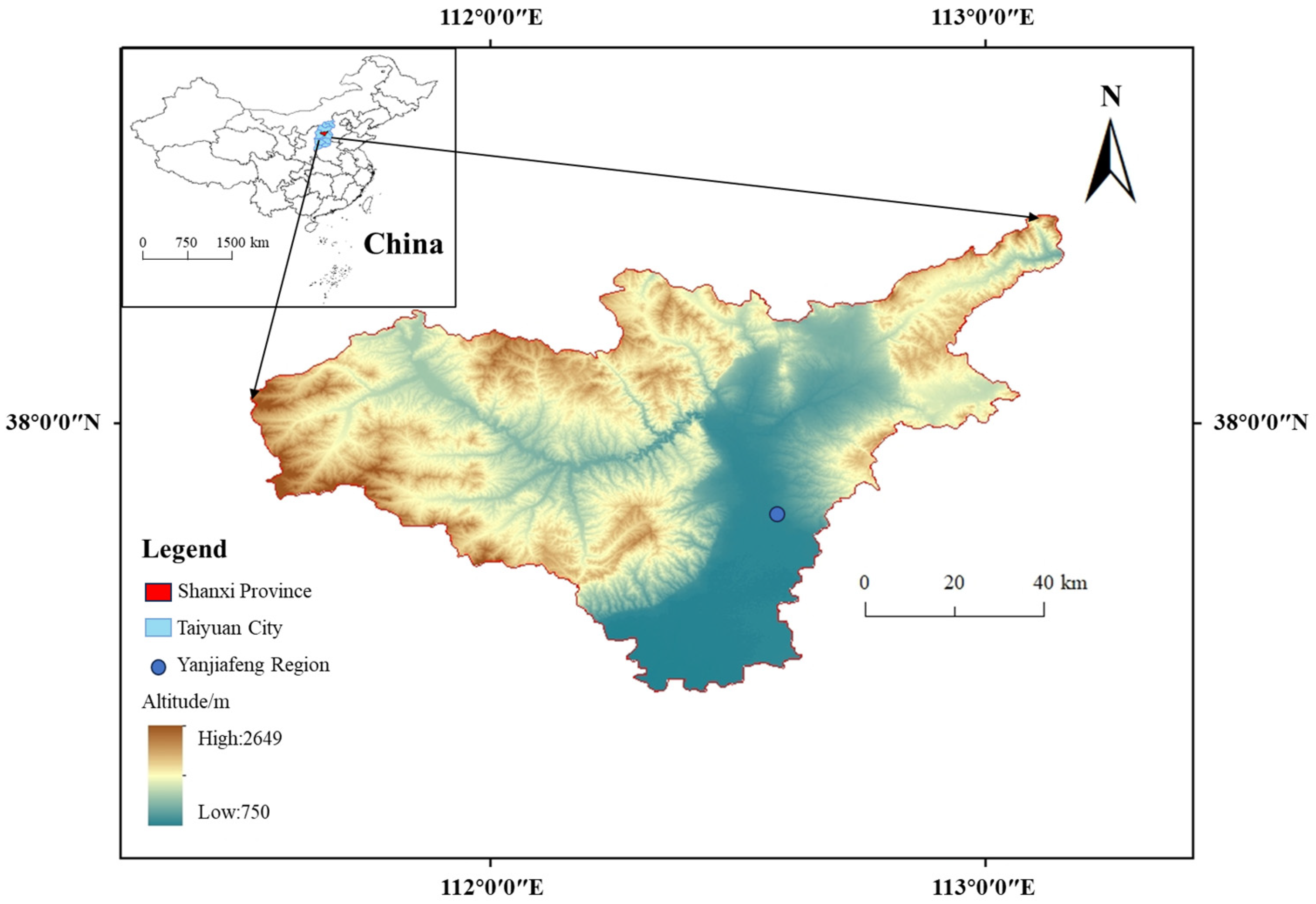
The proposed comprehensive compaction technology was first applied to a filled high embankment project at Yanjiafeng, Taiyuan. The Yanjiafeng filled high embankment is a section of the Taihang Road Project in Taiyuan, located between milestones K4 + 000 and K4 + 360. The site features an obvious topographic relief, and the geomorphic unit of the site is a loess hilly region. The original soil of the road foundation is loess with intermediate compression characteristics. The loess (Q3) near the site was applied as the filling material for the filled high embankment because of the large filling amount and the remote location. The loess was brownish yellow, with silty soil as the main component. The loess was slightly wet and dense. Table 2 lists its basic physical and mechanical properties. Due to the favorable geotechnical properties of the natural foundation beneath the embankment, no reinforcement measures were required. Figure 1 shows the location of the projects analyzed.
Table 2.
Physical and mechanical properties of the filling soil.
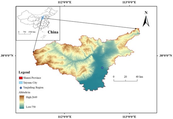
Figure 1.
Location map of the projects analyzed.
The construction procedure of the comprehensive compaction technology applied in the project is as follows. First, layered rolling refers to the layered compaction of filled loess of each lift using the vibratory rollers. The rolling parameters were determined as follows according to past construction experiences: 18 t vibratory rollers were applied to roll at a speed of 4 km/h, and the thickness of each lift must not exceed 0.3 m. The control moisture content and deviation were determined through the compaction tests.
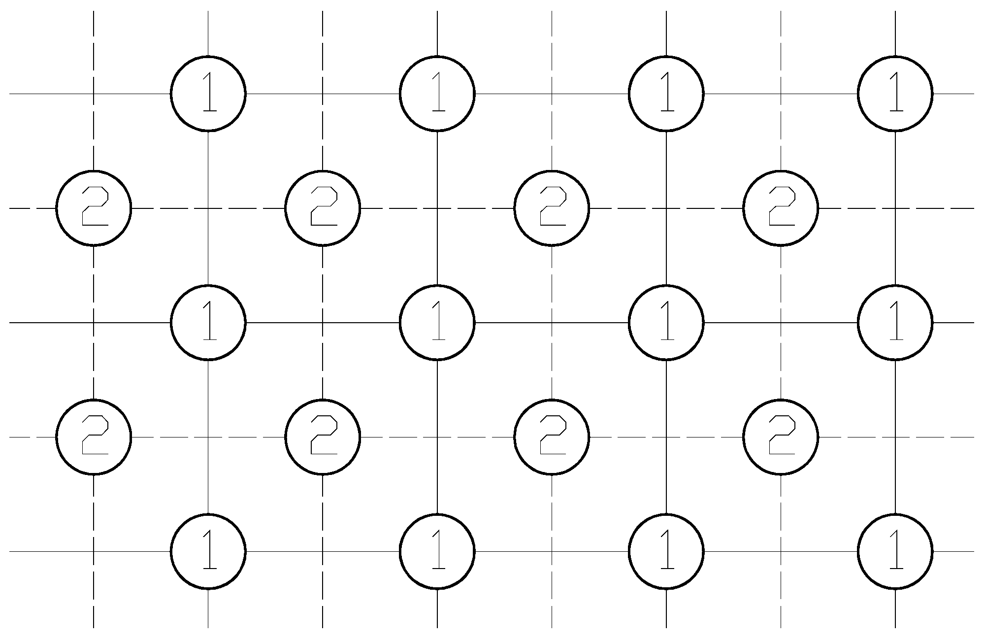
Second, heavy tamping was conducted each time the compaction reached a certain thickness. The major heavy tamping parameters included single-tamping energy and effective consolidation depth, which can be initially determined according to the Menard formula [17,18] and the local engineering experience. After optimization analysis, the single-tamping energy was determined as 500 kN·m, which is a value often used in projects. The effective consolidation depth was 3 m. Specific construction parameters are as follows: tamping hammer weight, 50 kN; falling distance, 10 m; heavy tamping layer thickness, 3 m. The heavy tamping was performed at rectangle grid points, and a pitch of approximately 1.6 times of the hammer diameter was applied. Figure 2 presents the distribution of the tamping points in the tamping region. Tamping was conducted three times, including the first time for the No. 1 major-tamping point, the second time for the No. 2 sub-tamping point, and the final time for full tamping. The termination criteria for each tamping layer include the following: (1) after reaching a certain number of tamps, the average tamping settlement of the final two tamps shall be smaller than 20 mm; (2) no excessive heave occurs surrounding the tamping pit, and (3) no excessively deep tamping pits form and affect the tamping operation.
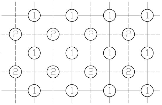
Figure 2.
Distribution diagram of the tamping points in the tamping region.
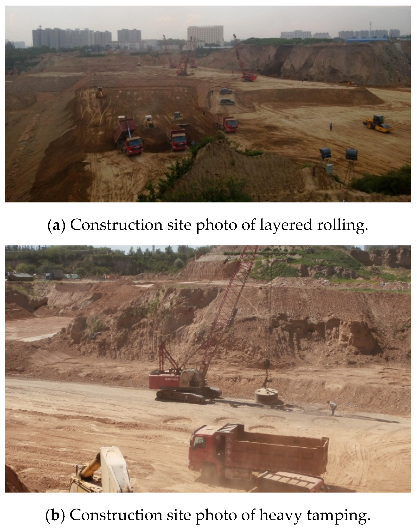
Figure 3a depicts the construction site photo of the layered rolling of the Yanjiafeng filled high embankment. Figure 3b shows the construction site photo of heavy tamping.

Figure 3.
Construction site photo of layered rolling and heavy tamping.
2.3. Soil Mechanics of Filling Soil
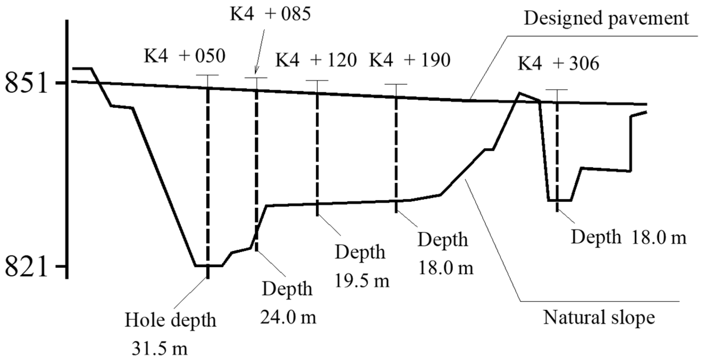
Figure 4 illustrates a longitudinal cross section of the Yanjiafeng filled high embankment. The maximum filling height of the embankment was 30 m, located at K4 + 050.

Figure 4.
Diagram of the engineering topography and the section location.
During the construction process of the Yanjiafeng filled high embankment, soil samples were extracted onsite, and laboratory tests such as compaction tests and consolidation compression tests were conducted. The soil sample extraction was a critical link, and the relevant methods are described below.
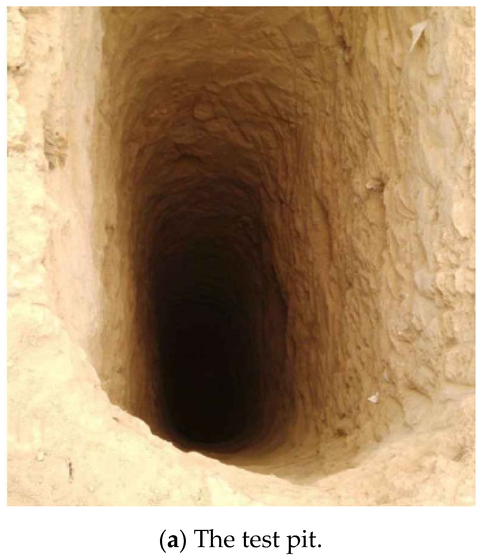
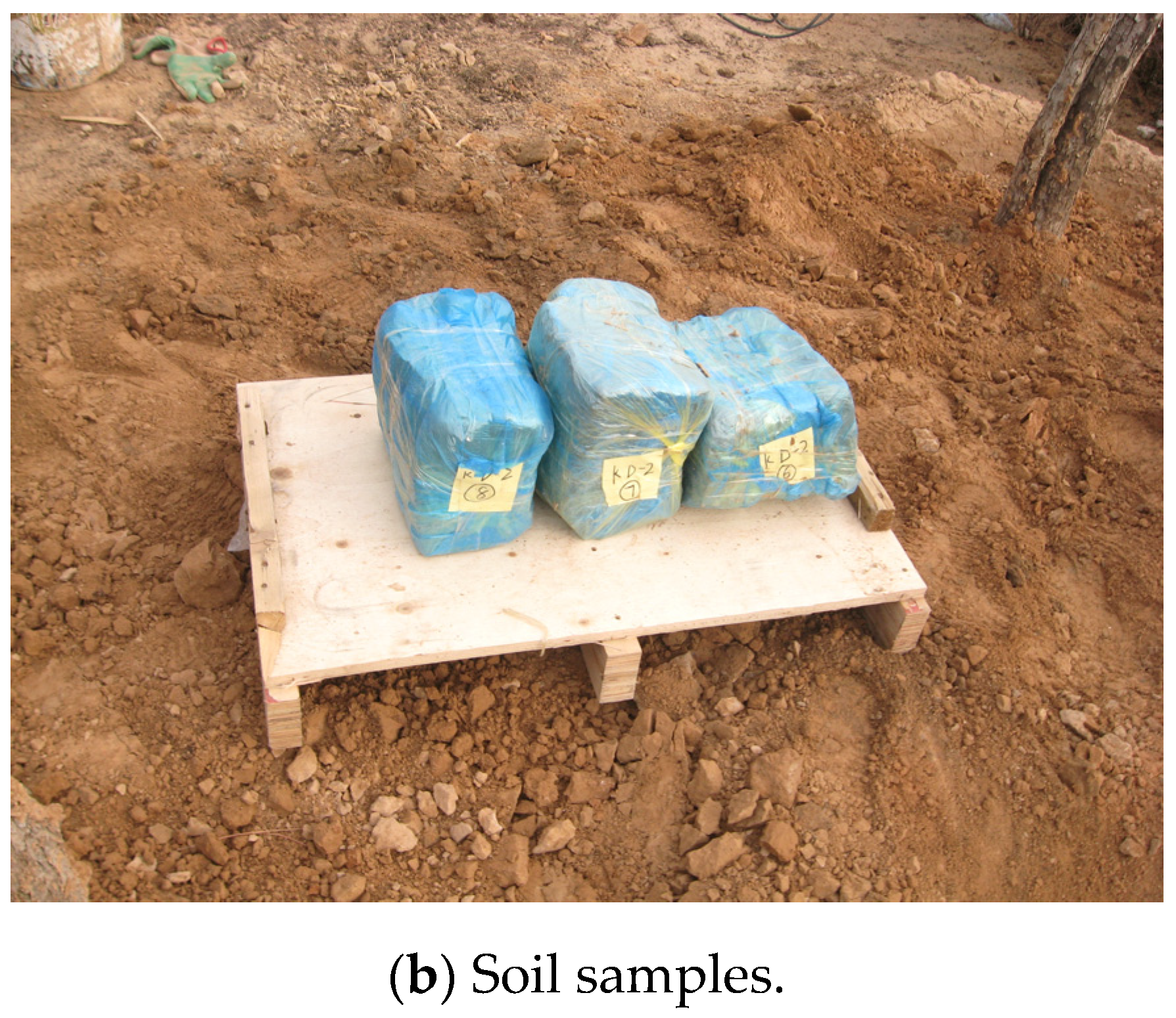
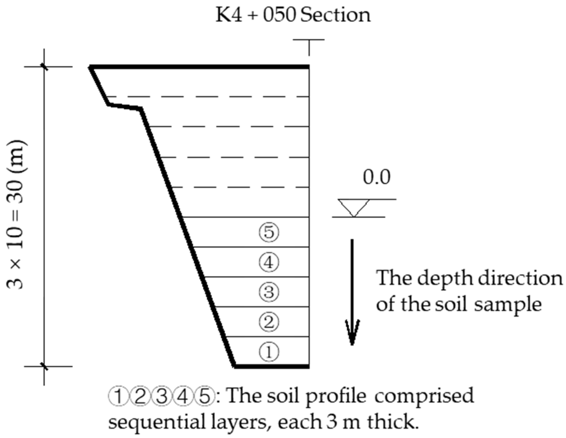
The comprehensive compaction technology applied in this project refers to the repeated construction of heavy tamping at each 3 m layer of fill being rolled. Therefore, upon construction completion for each 3 m thick filling layer, its physical and mechanical characteristics were the same. Two soil filling layers (6 m thick) were taken for relevant experiments. These layers represent the compaction and compression characteristics of the filling body. The detailed methods for extracting soil samples include the following: tracking the construction process at K4 + 050, whose filling height was 30 m (before construction to a height of 15 m). The soil samples were obtained by manually digging a test pit (Figure 5a). Two conditions were considered in soil extraction: the first kind of soil sample was obtained after rolling with rollers, and the other kind was obtained after heavy re-tamping after rolling. The soil extraction depth was 1–7 m. The depth was calculated with the top surface of construction to the height of 15 m as the zero point (as shown in Figure 6, all the following conditions involving the filling soil sample depth were the same). The fifth 3 m thick repeated construction ended exactly at the height of 15 m. A set of soil samples was extracted approximately every 0.5 m. The soil samples obtained onsite are shown in Figure 5b.

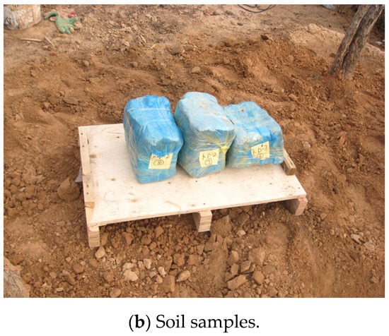
Figure 5.
A site photo of the test pit.

Figure 6.
Diagram of the depth direction of the soil sample.
2.4. Monitoring of Post-Construction Settlement
Settlement monitoring points were arranged on roads, and settlement magnet rings were distributed in embankment soil layers to measure the post-construction settlement of the filled high embankment. Digital leveling instruments and layered settlement instruments were utilized to monitor the settlement of the high embankment.
The topographic conditions of the road section indicated five settlement monitoring sections, namely, K4 + 050, K4 + 085, K4 + 120, K4 + 190, and K4 + 306. Three settlement monitoring holes were sunk in the east, middle, and west of the road on each section, and four measurement points were set up in each hole from the upper to the lower layers. The locations of the settlement monitoring holes are shown in Figure 4. In the layered settlement monitoring, the elevation changes in the settlement magnet rings at the monitoring points inside the embankment or the lower foundation were observed.
Upon completion of embankment construction, pavement construction was immediately conducted on the embankment and the highway was put into operation. Settlement monitoring was simultaneously started and continued for one year.
3. Results and Discussion
Due to the compressibility of the filling soil, large post-construction settlement and creep landslides of filled high embankments of 10–30 m in height are reported frequently in the literature [19]. The major control index for filled high embankments in construction is the degree of compaction of the filling soil [20,21]. Thus, the degree of compaction of the fills was measured during the construction process. Subsequently, the consolidation compression testing and onsite settlement monitoring were conducted.
3.1. Working Mechanism of Heavy Tamping
The key to the comprehensive compaction technology is to add a heavy tamping procedure based on the compaction of traditional rollers in each soil layer. Heavy tamping can be regarded as the dynamic tamping of low energy. Its tamping energy is lower than the dynamic tamping energy (i.e., generally under 1000 kN·m), and 500 kN·m is usually applied. The analysis results of the mechanics indices like the degree of compaction and compression modulus of the filling soil, which were mentioned earlier, showed that after being compacted by rollers, the working mechanism of heavy tamping for the loess layer was a re-compacting effect. In other words, the shock wave and the dynamic stress produced by the larger tamping energy spread through the soil, leading to an instantaneous relative motion of the soil particles that became closer to each other. The air bubbles trapped in the pores were rapidly discharged or compressed, and the pore volume further decreased to form a denser structure. Thus, the compression of the filling soil within a certain depth range was effectively reduced, and the loading capacity of the filling soil was simultaneously improved.
3.2. Degree of Compaction of the Embankment Soil
The degree of compaction is defined as
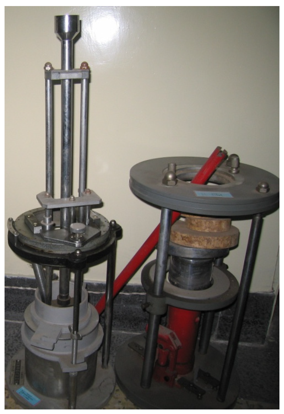
where refers to the maximum dry density obtained from the compaction tests (g/cm3), and refers to the dry density of the soil samples in the experiment (g/cm3). The maximum dry density, = 1.705 g/cm3, was obtained through the compaction testing of the original loess near the site. The corresponding optimal moisture content was = 13%. The compaction tests were conducted in accordance with relevant geotechnical testing standards. The soil pusher and compaction apparatus used in the compaction tests are shown in Figure 7.
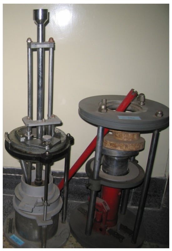
Figure 7.
Soil pusher and compaction apparatus.
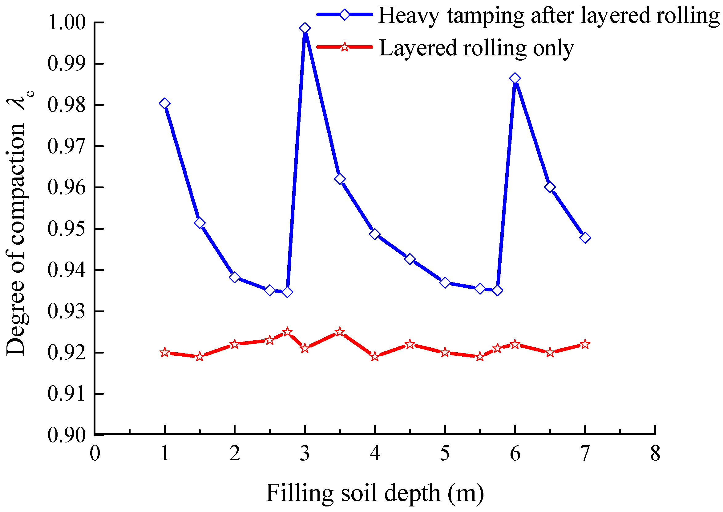
Through indoor experiments under two kinds of construction conditions (i.e., condition 1: only rolled using rollers and condition 2: heavy tamping after rolling), the changing curves of the degree of compaction and the void ratio e with the filling soil depth of the filled high embankment are as shown in Figure 8 and Figure 9, respectively.
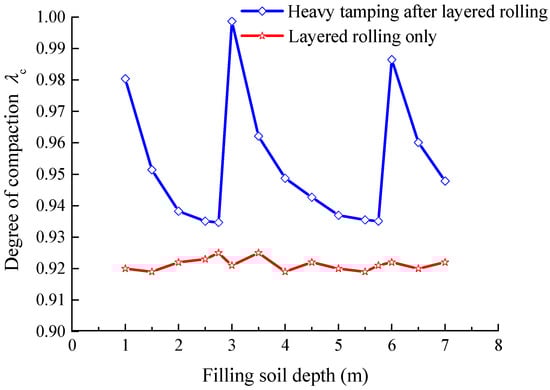
Figure 8.
Degree of compaction with filling soil depth.
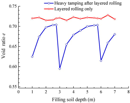
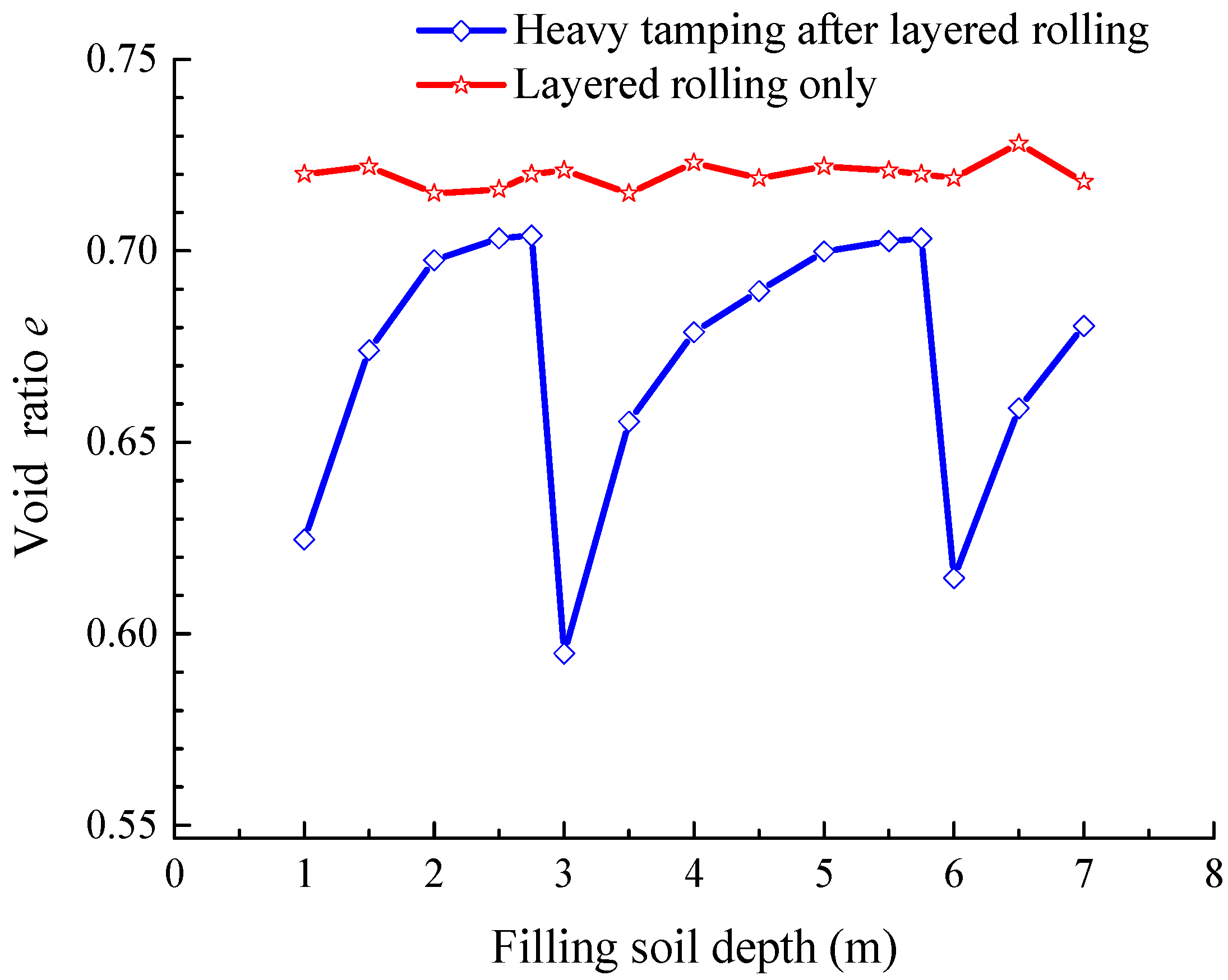
Figure 9.
Void ratio e with filling soil depth.
Figure 8 shows that the variation in the degree of compaction of the filling soil rolled using rollers only generally with the depth. The numerical values were approximately 0.92, indicating that the rolling effect of the rollers was relatively uniform. However, after rolling under strict construction control in this project, further improving the degree of compaction is quite difficult.
Figure 8 and Figure 9 show that the degree of compaction of each site with heavy tamping after layered rolling with vibratory rollers was further significantly improved. The degree of compaction reached a maximum, while the void ratio reached a minimum at the interface of heavy tamping (at depths of 3 m and 6 m). The degree of compaction gradually decreased before reaching the next peak, while the void ratio gradually increased. In a similar fashion, the compaction degree repeatedly changed according to this trend every time it reached a certain thickness of heavy tamping (3 m). In view of the abovementioned reasons, the degree of compaction of the embankment soil layers was first improved after layered rolling with the vibratory rollers. The degree of compaction of each site was relatively uniform because of the careful control of the rolling process. After heavy tamping every 3 m, the compaction density effect further improved the degree of compaction of the soil body. Improvement of the degree of compaction certainly varies with depth and tamping energy. Within the range of 3 m thickness, the soil layer closest to the tamping surface was most influenced by the tamping energy; hence, the improvement of the degree of compaction of the soil body reached the maximum. Starting from the tamping surface, the effect of the tamping energy gradually decreased with the increasing depth. The improvements of the degree of compaction of the soil body were also smaller. Figure 9 shows the changes in the void ratio of the soil, similar to those of the degree of compaction.
Figure 8 and Figure 9 also show that the changes in the degree of compaction and the void ratio tended to decelerate when reaching 2.5 m below the heavy tamping surface, indicating that the influence depth of heavy tamping under the tamping energy was 2.5–3.0 m, and the effects on the soil body below were weak. Therefore, in this project, the soil body was tamped every 3 m to effectively compact the fill.
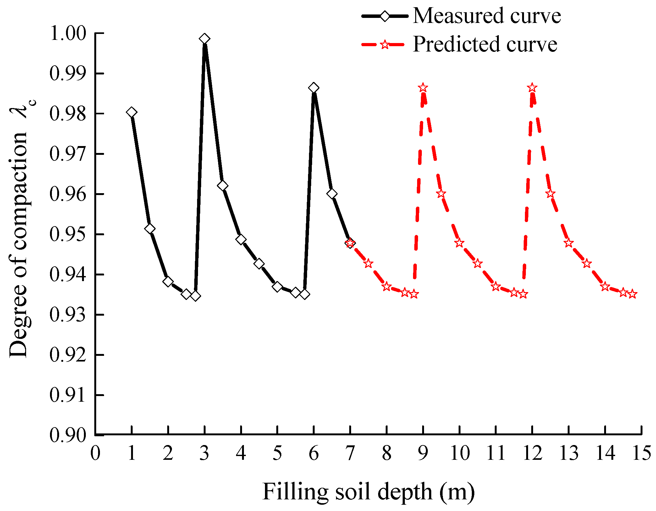
Expanding the soil filling depth in Figure 8 is feasible to better illustrate the changing principles of the degree of compaction of the embankment soil body. Figure 10 shows the changing curve of the degree of compaction with depth after expansion, where the prediction data were drawn in dotted lines. Figure 10 also demonstrates that the degree of compaction periodically changes with depth, with the period relating to the thickness of heavy tamping. The degree of compaction suddenly changes at the interface of heavy tamping; thus, the curve appears as a periodically changing sawtooth shape.

Figure 10.
Degree of compaction with depth after expansion.
3.3. Compression Modulus of the Embankment Body
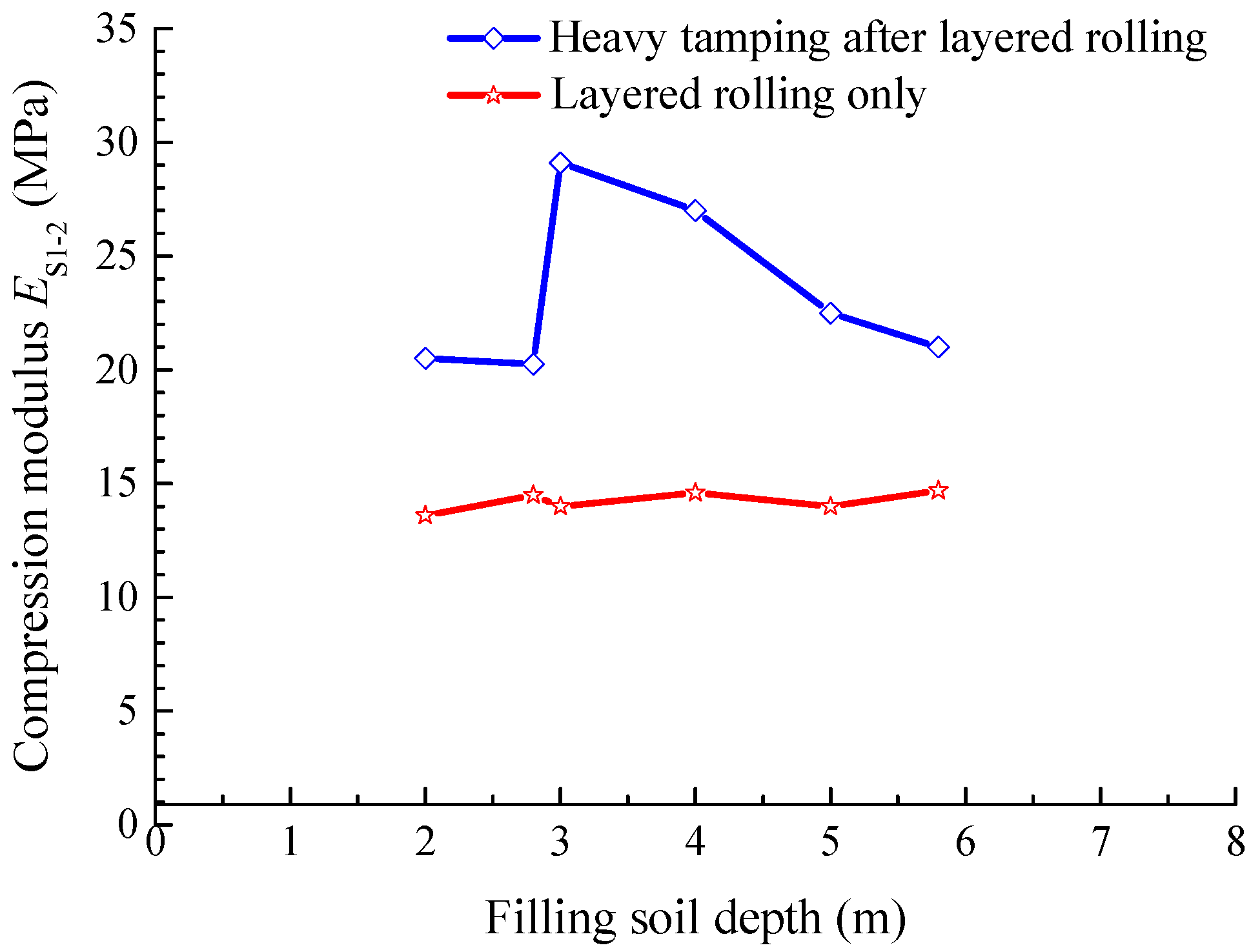
Odometer tests were used to investigate the compression properties of compacted filling soil and obtain the compression modulus of the soil. The selected depths of the soil samples in this experiment were 2, 2.8, 3, 4, 5, and 5.8 m. For convenience of comparison, the compression modulus Es1–2 at the pressure range that increased from = 100 kPa to = 200 kPa was generally applied to represent the compression properties of the soil body. Figure 11 shows the relationship between the compression modulus and the filling soil depth under the two circumstances, including layered rolling only and heavy tamping after layered rolling.
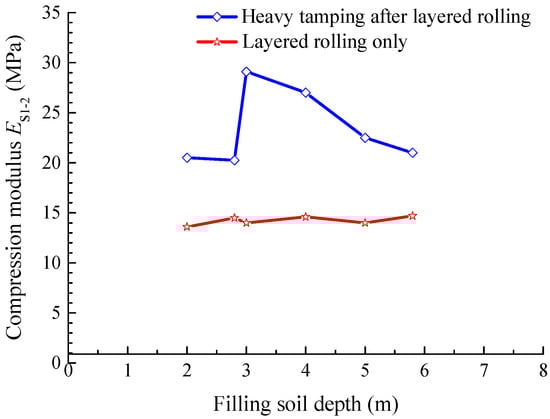
Figure 11.
Relationship between the compression modulus and the soil layer depth under layered rolling only and heavy tamping after layered rolling.
Figure 11 shows that the compression modulus after layered rolling with rollers generally changes with the filling soil depth, indicating that the rolling effects were relatively uniform. After heavy tamping of the filling soil, the compression modulus of the soil samples at each depth was improved to different extents: by 50–100% compared to those only with layered rolling using the rollers. Furthermore, the compression modulus at the depth of 3 m (the surface of heavy tamping) reached the maximum, after which it gradually decreased to its minimum before reaching the next tamping surface (6 m). These changes repeated over each heavy tamping thickness (3 m), showing the same change principles as for the degree of compaction mentioned earlier.
The difference between the compression modulus after heavy tamping and the basic control variable is exactly the increment of the compression modulus of the soil layer after heavy tamping if the compression modulus with layered rolling using rollers only is used as the basic control variable. Figure 12 depicts the changing curve of the increment with the filling soil depth, where the solid line denotes the actual measured values, and the dotted line represents the predicted values. The curve also shows a periodic sawtooth shape. Apparently, heavy tamping led to the periodic modulus increment, which further reduced the compression settlement of the filling body. The reduction degree will be discussed later in this paper along with the settlement calculation formulas.
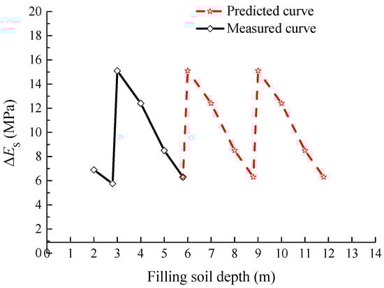
Figure 12.
Predicted and measured values of the compression modulus.
The quantitative relationship of the compression settlement and the compression modulus for each soil layer of the embankment is expressed as
where refers to the vertical stress (kPa), and refers to the thickness of the soil layer (m). As described earlier, the compression modulus of the filling body repeatedly changed at every 3 m of heavy tamping thickness. Thus, applying Equation (2) is feasible to comparatively analyze the compression settlement of the filling body with a thickness of 9–30 m under the effect of self-weight stress according to the experimental data for the compression modulus in Figure 11. The compression settlement of the filling body only with layered rolling is h1, and the compression settlement of the filling body with heavy tamping after rolling using rollers is h2. Table 3 presents the calculation of h2/h1 and (h1 − h2)/h1 (settlement reduction ratio).
Table 3.
Comparative analysis of the compression settlement of the filling body with different compaction methods.
The values in Table 3 allow for a comparison of the common loess-filled high embankment, whose filling height was 9–30 m, with the settlement of the filling body using only layered rolling. The results indicated that the settlement of the filling body using both layered rolling and interlayer heavy tamping can be reduced by almost 40%.
3.4. Post-Construction Settlement
Under the effect of gravity loading on the filling soil and vehicle dynamic load on the upper road, the total post-construction settlement of the road surface S can be regarded as the combination of the post-construction settlement of filling body S1 and the post-construction settlement of the original foundation at the bottom of embankment S2, that is, S = S1 + S2. Figure 13 shows the settlement monitoring results, taking the central measuring points at sections K4 + 050 and K4 + 190 as examples. Table 4 presents the final (at the end of monitoring) settlement results of the two sections.
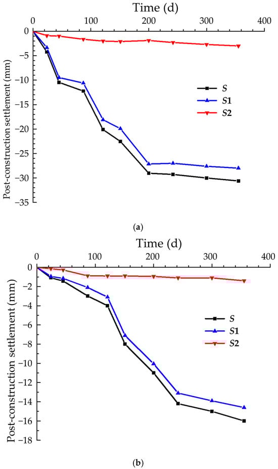
Figure 13.
Post-construction settlement: (a) K4 + 050 section and (b) K4 + 190 section.
Table 4.
Displacement values at the final settlement.
Figure 13 and Table 4 show that the maximum total post-construction pavement settlement of a filled high embankment at section K4 + 050 was 30.61 mm, of which the post-construction settlement of the filling body was 27.59 mm (0.092% of the embankment height), approximately 90% of the total settlement. The post-construction settlement of the original foundation was 3.02 mm, approximately 10% of the total settlement. The post-construction settlement of the filling body at section K4 + 190 with an 18 m fill was 14.68 mm (0.086% of the embankment height), approximately 91.3% of the total settlement.
For the post-construction settlement in this project, the filling body itself became the major constituent of the total post-construction pavement settlement of the filled high embankments through compression deformation. Thus, the key to construction in filled high embankments lies in the control of the compression settlement of the filling body itself through reasonable compaction methods. From the comparison with the actual measurement data from the embankment project in Table 1, the relative post-construction settlement of the filling body (the ratio of settlement to embankment height) after applying the comprehensive compaction technology was less than 0.1%, which was far less than the relative settlement for the embankment projects with layered rolling only. A smaller post-construction settlement not only greatly satisfied the requirements of the relevant specifications toward the limit values of the pavement settlement for filled high embankments but also omitted the reserved settlement period, leading to huge social and economic benefits.
Figure 13 also shows that the settlement rate of the filling body generally illustrated the pattern of being large at first and small later on, tending to be stable in time. An apparent acceleration feature occurred at approximately the 100th day in the settlement curve, which can be analyzed in consideration of the road traffic situation in Taiyuan that year. With an apparent increase in the vehicle flow, the vehicle loading accelerated the further compaction of the loess fill, increasing the settlement rate of the soil fill at each layer of the embankment. Since then, with the gradual compaction of the embankment filling soil and the original foundation soil, the settlement rate gradually slowed down, and the settlement value tended to be stable in approximately 240 to 365 days.
3.5. Post-Construction Settlement Prediction
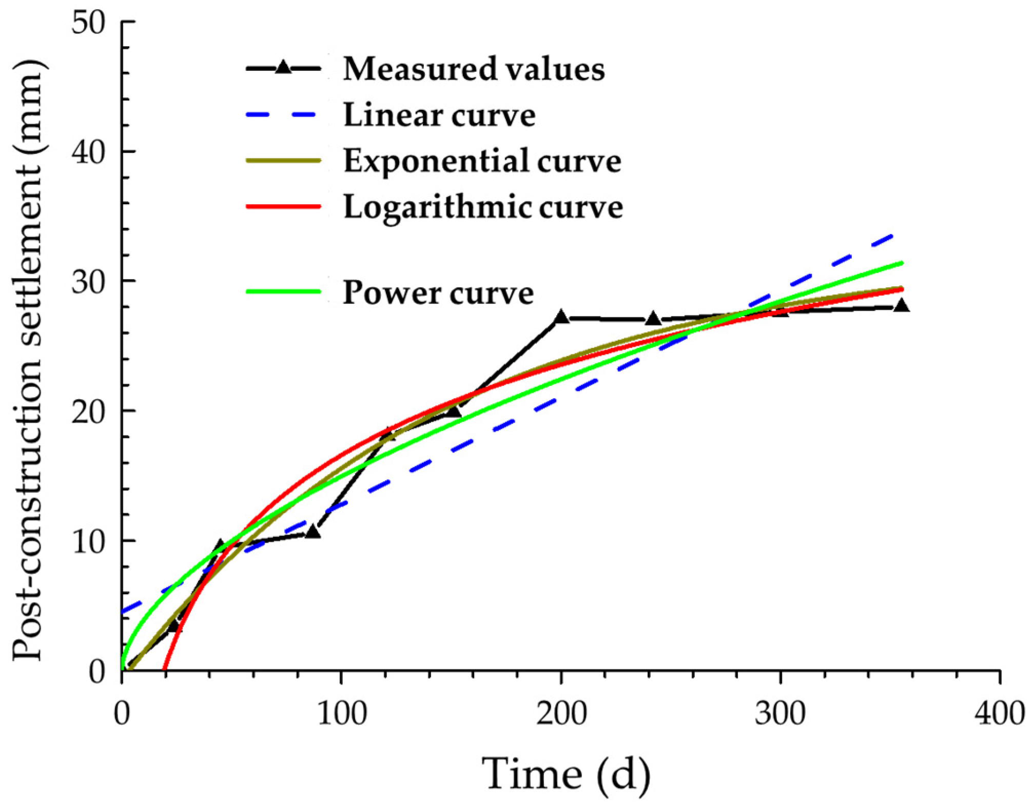
Numerous prediction methods have been suggested in the literature [22], and the curve-fitting method can adequately capture the settlement features of high embankments [23,24,25,26,27]. Taking the data for section K4 + 050 as an example, regression analysis with linear, exponential, logarithmic, and power functions was applied separately to conduct curve fitting on the measured post-construction settlement data for a filling body. Figure 14 depicts the fitted curves and the actual measurement values. Table 5 presents the fitting results. Figure 14 and Table 5 show that the maximum R2 value is achieved through fitting with a logarithmic curve, indicating that the logarithmic curve is closest to the actual measured values. In other words, the post-construction settlement of the filling body and time were essentially in a logarithmic relationship. The settlement during the initial stage was larger and finally tended to be stable.
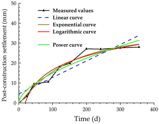
Figure 14.
Fitted curves and measured values for the post-construction settlement.
Table 5.
Fitting curve models and parameters.
The post-construction settlement of the filling body increased with time following a logarithmic relationship; hence, the prediction formula of the post-construction settlement of the filling body is proposed as
where S/H refers to the relative settlement (%); H refers to the soil filling height (m); S refers to the post-construction settlement of the filling body (m); t refers to the post-construction time (days); and a and b refer to the calculation parameters, whose values were related to the nature of the filling material and the filling methods in construction, respectively.
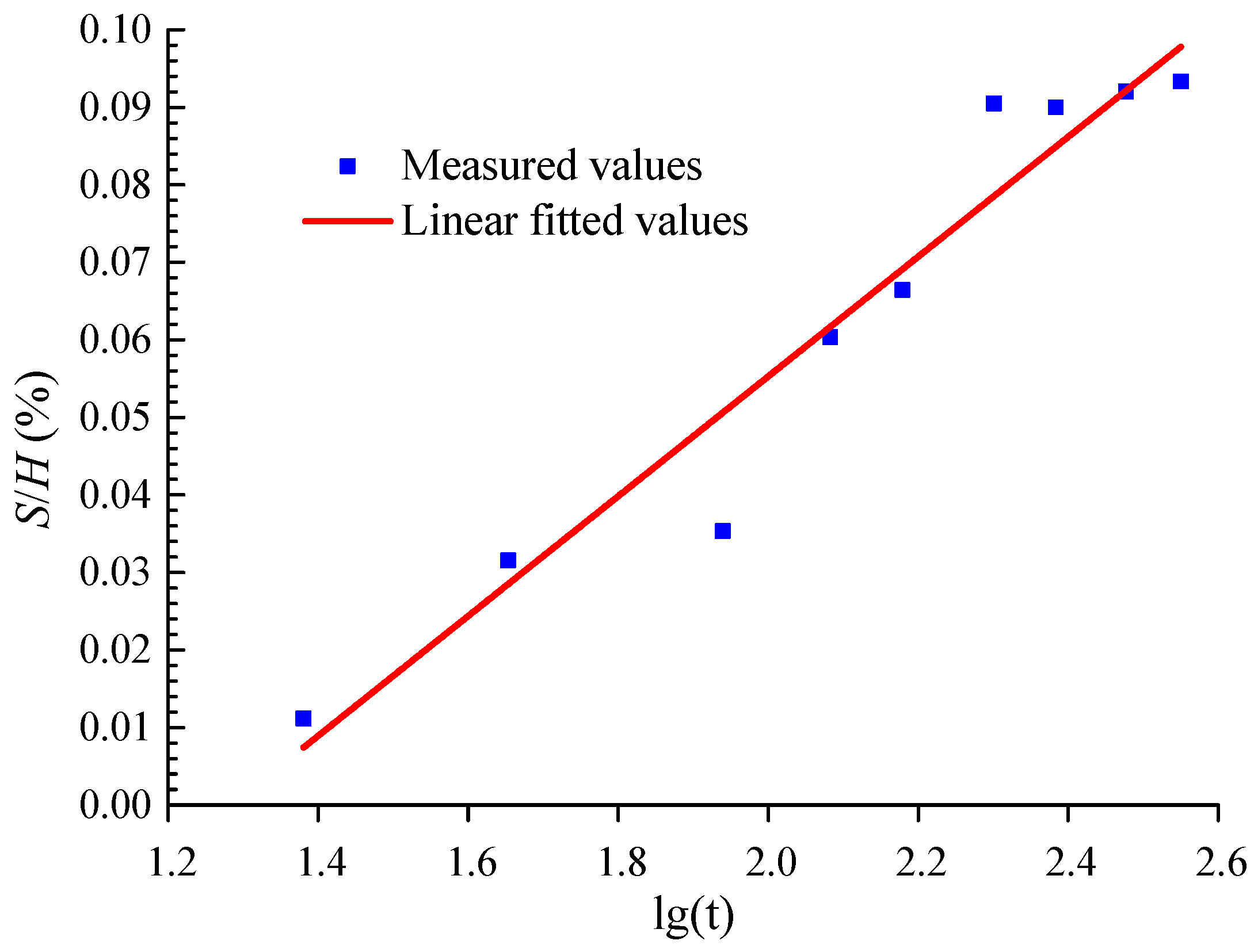
Linear fitting was conducted according to the actual measurement values from the post-construction settlement of the filling body of section K4 + 050 (Figure 15) and the other sections, through which the calculation parameters were obtained as a = 0.08 and b = 0.1. These two parameters were substituted into Equation (3), through which the post-construction prediction formula for a loess-filling body (the properties of the fill are similar) appropriate for comprehensive compaction technology was obtained as
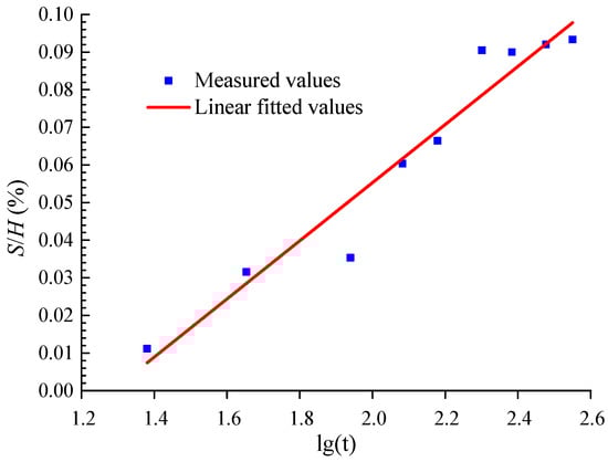
Figure 15.
Relationship between S/H and lg(t) of the K4 + 050 section.
3.6. Discussion on the Application of Analogous Engineering
Construction methods similar to this comprehensive compaction method have already been applied in the high-fill foundation of Luliang Airport in Shanxi Province [4,28]. The fill materials for Luliang Airport project mainly consist of Q2 and Q3 loess, with a maximum fill depth of approximately 80 m. The compaction method employed in this project combines roller layer-by-layer compaction with dynamic consolidation. The single impact energy for dynamic consolidation exceeds 1000 kN·m, and consolidation is carried out every 3 to 4 m in the thickness direction. Researchers conducted nearly two years of continuous in situ monitoring tests onsite. The test results indicated that the post-construction settlement of the 80 m thick fill body was 30 mm (0.04% of the fill height), and the post-construction settlement of the 15 m thick fill body was 8 mm (0.05% of the fill height). These settlement data all met the design requirements, demonstrating the excellent compaction effectiveness of this construction method.
4. Conclusions
A comprehensive compaction technology that combines layered compaction by vibratory rollers and interlayer heavy tamping was proposed to improve the compaction effects of high loess embankments. The technology was combined with engineering applications, soil mechanics testing, and onsite settlement monitoring to investigate the compression characteristics of the rolled and tamped loess fill. The effective tamping thickness was 3 m, and the applied single-tamping energy was 500 kN·m. The following conclusions were drawn:
- (1)
- When a filling soil with layered rolling experienced heavy tamping, its degree of compaction and compression modulus were greatly improved and appeared in a periodic sawtooth curve shape according to the filling depth. The analysis results for the degree of compaction, compression modulus, and post-construction settlement of the filling body show that for the loess layers after compaction by rollers, the working mechanism of further heavy tamping was a re-compacting effect.
- (2)
- Compared to the compression modulus of the filling soil with layered rolling using rollers only, the compression modulus was improved by 50–100% with comprehensive compaction. Further analysis of the compression modulus showed that compared to the settlement with layered rolling only, the settlement of the filling body with comprehensive compaction can be reduced by almost 40%.
- (3)
- The settlement monitoring results showed that the settlement rate of the filling body with comprehensive compaction tended to be large at first and subsequently smaller over time. The post-construction settlement of the filling body that finally tended to be stable was smaller than 0.1% of the embankment height, which was significantly reduced compared to similar embankment projects using layered rolling only. The compression deformation of the filling body itself in this project was the major constituent of the total settlement.
- (4)
- The post-construction settlement of the filling body increases with time following a logarithmic relationship.
- (5)
- The comprehensive compaction technology can be used to enhance the embankment compaction effects, effectively reducing post-construction settlement for the loess-filled high embankment.
- (6)
- Construction parameters for the comprehensive compaction technology should be appropriately optimized based on different soil properties before implementation.
Author Contributions
Validation, C.Z.; Data curation, Y.C.; Writing—original draft, Y.C.; Writing—review & editing, G.Z. and Y.J.; Visualization, C.Z.; Supervision, Y.J.; Funding acquisition, Y.J. All authors have read and agreed to the published version of the manuscript.
Funding
This research was funded by the National Natural Science Foundation of China (No. 51178287), the Natural Science Foundation of Shanxi Province, China (No. 2011011024-1), the Science and Technology Development Project of Taiyuan Rail Transit Group Co., Ltd., China (No. KY20201001), and the Science and Technology Development Project of Beijing Municipal Construction Group Co., Ltd., China (No. 20140801).
Data Availability Statement
Data used for this work are available upon reasonable request.
Conflicts of Interest
Author Yimei Cheng was employed by the company Taiyuan Rail Transit Group Co., Ltd. The remaining authors declare that the research was conducted in the absence of any commercial or financial relationships that could be construed as a potential conflict of interest.
References
- Goktepe, F.; Keskin, I. A Comparison Study between Traditional and Finite Element Methods for Slope Stability Evaluations. J. Geol. Soc. India 2018, 91, 373–379. [Google Scholar] [CrossRef]
- Yang, C.W.; Zhang, J.J.; Wang, Z.Z.; Hou, J.Q.; Si, C.L. Model Test of Failure Modes of High Embankment and Aseismic Measures for Buried Strike-Slip Fault Movement. Environ. Earth Sci. 2018, 77, 233. [Google Scholar] [CrossRef]
- Nazir, N.; Moayedi, H.; Subramaniam, P.; Gue, S.S. Application and Design of Transition Piled Embankment with Surcharged Prefabricated Vertical Drain Intersection over Soft Ground. Arab. J. Sci. Eng. 2018, 43, 1573–1582. [Google Scholar]
- Jie, Y.X.; Wei, Y.J.; Wang, D.L.; Wei, Y.F. Numerical Study on Settlement of High-Fill Airports in Collapsible Loess Geomaterials: A Case Study of Lüliang Airport in Shanxi Province, China. J. Cent. South Univ. 2021, 3, 939–953. [Google Scholar] [CrossRef]
- Tang, D.; Yang, Y.H. Calculation and Analysis of Relationship Between Embankment Height and Settlements Deformation. Technol. Highw. Transp. 2007, 9, 1–3. [Google Scholar]
- Meng, X.Q.; Wei, X.Y.; Liang, L. Probe into Boundary Pressure and Boundary Water Content for the Deformation of Collapsible Loess. Sci. Tech. Inf. Dev. Econ. 2000, 10, 44–45. [Google Scholar]
- Li, J.; Bai, X.H.; Ma, F.L. Energy Transfer and Influencing Factors in Soil during Compaction. PLoS ONE 2020, 20, e0242622. [Google Scholar] [CrossRef]
- Buathong, P.; Chompoorat, T.; Jongpradist, P.; Chen, X.; Jamsawang, P. Effect of Palm Fiber Reinforcement on the Unconfined Compressive Performance of Cement-Treated Sand. Sustainability 2023, 15, 8607. [Google Scholar] [CrossRef]
- Chompoorat, T.; Thepumong, T.; Taesinlapachai, S.; Likitlersuang, S. Repurposing of stabilised dredged lakebed sediment in road base construction. J. Soils Sediments 2021, 21, 2719–2730. [Google Scholar] [CrossRef]
- Wang, J.L.; Liu, Y.L.; Shen, X.F.; Peng, S.P. Experimental Investigation on Treatment of Loess Subgrade with Impaction and Grind Method (IGM). Rock Soil Mech. 2005, 26, 755–758. [Google Scholar]
- Lou, G.C. Application of Impact Compaction Technology in Highway Embankment of Collapsiable Loess Soils. Chin. J. Rock Mech. Eng. 2005, 24, 1207–1210. [Google Scholar]
- Jing, H.J.; Zhang, B. Experiments of Highway Subgrade Impact Compaction in Loess Region. J. Chang’an Univ. (Nat. Sci. Ed.) 2004, 24, 25–29. [Google Scholar]
- Feng, J.; Liu, Y.J.; Lu, X.M.; Chen, Z.K.; Wu, J.; He, J.Z.; Zhao, Z.Y. Engineering Characteristics of Unsaturated Cohesive Foundation Soil at High-Plateau Airport with Considering the Embankment Filling Interval. Pol. J. Environ. Stud. 2024, 33, 1111–1120. [Google Scholar] [CrossRef]
- Xu, J.M.; Wu, X.Y.; He, H.; Mao, Y.F. Experimental Study of the Pore Pressure Variation during EPB Shield Tunnelling in the Saturated Sand. Tunn. Undergr. Space Technol. 2025, 161, 106576. [Google Scholar] [CrossRef]
- Su, Y.H.; Du, R.F.; Bai, Z.P. Experimental Study on Settlement and Stability Observation of High-Fill Embankment in the Jining-Fengzhen Section of the Freeway208. J. Inner Mong. Agric. Univ. 2007, 28, 154–158. [Google Scholar]
- Liu, F.Y.; Zhao, R.; Xie, D.Y.; Zhao, X.M. Settlement of Loess-Filled Highway Embankment. J. Chang’an Univ. (Nat. Sci. Ed.) 2003, 23, 23–28. [Google Scholar]
- Das, B.M. Principles of Geotechnical Engineering; Cengage Learning: Belmont, CA, USA, 2012. [Google Scholar]
- Ghassemi, A.; Pak, A.; Shahir, H. Validity of Menard Relation in Dynamic Compaction Operations. Proc. Inst. Civ. Eng. Ground Improv. 2009, 162, 37–45. [Google Scholar] [CrossRef]
- Huo, M. Guide to Survey and Design of High-Speed Road in Mountain Area; People’s Transportation Publishing House: Beijing, China, 2003. [Google Scholar]
- Zhang, L.M.; Yu, X.M.; Hu, T. Optimization of Compaction Zoning in Loess Embankments. Can. Geotech. J. 1998, 35, 611–621. [Google Scholar] [CrossRef]
- Zhang, H.L.; Wu, H.J. Construction Technology of Subgrade Filling; People’s Transportation Publishing House: Beijing, China, 2008. [Google Scholar]
- Xu, J.M.; Wang, Y.K.; Gao, M.; Ni, J.J.; Gao, L.Q. Effects of Foundation Pressure and Building Stiffness on Tunnel-Separated Footing Interaction. Can. Geotech. J. 2025, 1–47. [Google Scholar] [CrossRef]
- van Leeuwen, M.M.W.J.; Heuvelink, G.B.M.; Wallinga, J. Visual Soil Evaluation: Reproducibility and Correlation with Standard Measurements. Soil Tillage Res. 2018, 178, 167–178. [Google Scholar] [CrossRef]
- Emadali, L.; Motagh, M.; Haghighi, M.H. Characterizing Post-Construction Settlement of the Masjed-Soleyman Embankment Dam, Southwest Iran, Using TerraSAR-X SpotLight Radar Imagery. Eng. Struct. 2017, 143, 261–273. [Google Scholar] [CrossRef]
- Kermani, M.; Konrad, J.M.; Smith, M. An Empirical Method for Predicting Post-Construction Settlement of Concrete Face Rockfill Dams. Can. Geotech. J. 2017, 54, 755–767. [Google Scholar] [CrossRef]
- Pan, L.Y.; Xie, X.Y. Observational Settlement Prediction by Curve Fitting Methods. Rock Soil Mech. 2004, 25, 1053–1058. [Google Scholar]
- Wang, Z.L.; Huang, J.Z.; Li, Y.C. Study on Application of Asaoka’s Method to Settlement Prediction. Rock Soil Mech. 2006, 27, 2025–2032. [Google Scholar]
- Zhu, C.H.; Li, N.; Liu, M.Z.; Wei, Y.F. Spatiotemporal Laws of Post-Construction Settlement of Loess-Filled Foundation of Lüliang Airport. Chin. J. Geotech. Eng. 2013, 2, 293–301. [Google Scholar]


Disclaimer/Publisher’s Note: The statements, opinions and data contained in all publications are solely those of the individual author(s) and contributor(s) and not of MDPI and/or the editor(s). MDPI and/or the editor(s) disclaim responsibility for any injury to people or property resulting from any ideas, methods, instructions or products referred to in the content. |
© 2025 by the authors. Licensee MDPI, Basel, Switzerland. This article is an open access article distributed under the terms and conditions of the Creative Commons Attribution (CC BY) license (https://creativecommons.org/licenses/by/4.0/).