Article

Interfacial Shear Behavior of Novel Connections Between Concrete Bridge Piers and Anti-Overturning Steel Supporting Joists

1
School of Civil and Transportation Engineering, Guangdong University of Technology, Guangzhou 510006, China
2
Guangdong Provincial Highway Construction Co., Ltd., Guangzhou 510623, China
3
Guangzhou Expressway Operation Management Co., Ltd., Guangzhou 510220, China
4
Department of Civil and Environmental Engineering, Northwestern University, Evanston, IL 60208, USA
*
Author to whom correspondence should be addressed.
Buildings 2025, 15(8), 1299; https://doi.org/10.3390/buildings15081299
Submission received: 4 March 2025 / Revised: 19 March 2025 / Accepted: 14 April 2025 / Published: 15 April 2025

Abstract

:
Additional steel supporting joists (ASSJs) can effectively enhance the anti-overturning capacity of the existing solo-column concrete pier (SCP) bridges. Although the interface consists of bolt connections between steel and concrete is the crucial load-transmitting portion, the design of the interface between the ASSJ and SCP still mainly relies on practical experiences. In an actual bridge rehabilitation project with ASSJs in China, a novel connection comprising large-diameter bolts and an epoxy resin layer was adopted to overcome the shortcomings of the initial design. In this study, connections composited with large-diameter bolts and different interfacial treatments were investigated. Four push-out tests on the interfacial shear performance of steel–concrete connections were carried out. The experimental parameters encompassed the interface treatment method (barely roughened surface, smearing epoxy resin, and filling epoxy mortar) and the number of bolts (single row and double rows). The failure modes were unveiled. According to the experimental results, the interfacial treatment method with filling epoxy mortar could uniformly transfer stress between concrete and steel and improve the shear stiffness and shear resistance of the steel–concrete connections. Compared with specimens with barely roughened interfaces, epoxy mortar and epoxy resin employed at the steel–concrete interface can increase the shear-bearing capacity of connections by approximately 47.71% and 43.46%, respectively. However, the interfacial treatment method with smearing epoxy resin resulted in excessive stiffness of the shear members and brittle failure mode. As the number of the bolts increased from a single row to a double row, the shear-bearing capacity of a single bolt in the specimen exhibited approximately an 8% reduction. In addition, by comparing several theoretical formulae with experimental results, the accurate formula for predicting the shear-bearing capacity of bolts was recommended. Furthermore, the load-bearing capacity of an ASSJ in the actual engineering rehabilitation was verified by the recommended formula GB50017-2017, which was found to accurately predict the shear-bearing capacity of large-diameter bolt connectors with an epoxy mortar layer.

1. Introduction

Due to the advantages of aesthetical appearance, convenient construction, and less occupying terrain, solo-column concrete pier bridges are widely used in urban overpasses and flyover ramps worldwide [1,2]. In the previous design of SCP bridges, the anti-overturning capacity of SCP bridges was inadequately considered, occasionally resulting in the transverse overturning accidents.
In the past few years, there were several typical overturning catastrophes of SCP bridges worldwide. On 19 June 2015, the bridge superstructure of a ramp of the Yuegan Expressway in the Guangdong Province of China overturned due to the passage of four overloaded trucks [2]. On 10 October 2016, the upper structure of a viaduct on National Highway 312 in Wuxi City of China overturned due to the overloading of trucks [3]. On 18 December 2021, a major bridge girder overturned on the Huahu Interchange in the Hubei Province of China, resulting in four deaths and eight injuries, and leading to a direct economic loss of 30.2 million yuan [4]. It is worth noting that similar accidents have also occurred worldwide. On 3 July 2010, a serious bridge collapse occurred in the Shimla district of India, where four fully loaded vehicles parked on the same side led to the collapse of the deck of the newly built bridge, resulting in two deaths [5]. In addition, on 3 March 2013, a truck filled with marble slabs in Kolkata caused the collapse of the Ultadanga overpass [6].
ASSJs for strengthening the SCP bridges can significantly improve the anti-overturning capacity of the superstructure of SCP bridges [7] (see Figure 1). ASSJs are connected with concrete columns through post-anchored bolts and paste materials. The special layer between the ASSJs and SCPs forms a composite structure of concrete column, post-anchored bolts, paste material layer, and steel plate. As a crucial structure of internal force transfer between ASSJs and SCPs, the interfacial shear behaviors of the composite connections determine the load-bearing capacity of ASSJs [8,9,10].
Figure 2 shows ASSJs in a rehabilitation project for enhancing the anti-overturning capacity of an SCP bridge in Guangzhou City China. The single supporting system of the original SCP did not meet the recent anti-overturning requirements. An ASSJ was added to the top of the original SCP, and one supporting pad was added on each side of the ASSJ at a distance of 1.0 m from the original support center, which transformed the original single supporting system into three supporting systems. The ASSJ was constituted of two half-prefabricated steel members through horizontal splicing bolts, with 72 post-anchored bolts arranged on the semi-circumferential sides of each half-steel member. The vertical load born by the ASSJ was transmitted from the connections to the SCP.
In the initial design of steel–concrete connections in ASSJs, post-anchored bolts with smearing epoxy resin between steel and concrete were suggested. The use of epoxy resin provides high rigidity and excellent bonding strength at the steel–concrete interface, significantly enhancing the interfacial shear behavior [11,12]. Additionally, the application of epoxy resin also helps to reduce micro-crack formation in the concrete, further enhancing the overall structural performance and longevity of the connection [13]. However, the concrete column would be roughened by manual chipping, which results in a rugged surface. The thin-layer epoxy resin could not sufficiently saturate the gap between steel and concrete in practical construction, leading to uneven stress transferring. Therefore, a novel connection solution combined with 30 mm large-diameter bolts and a high-performance epoxy mortar layer was proposed. This approach utilizes large-diameter bolts to minimize the number of drilling operations, thereby reducing damage to the original structure while maintaining structural performance. Furthermore, a 2.0 cm slot was reserved between the ASSJ and SCP after the concrete surface roughening, and a high-performance epoxy mortar was filled into the slot. Conventional methods typically rely on smaller-diameter bolts and thin epoxy resin layers, which often result in uneven stress transfer, localized stress concentrations, and brittle failure modes. In contrast, the proposed connection method can effectively overcome the drawbacks of smearing epoxy resin at in situ construction.
In recent years, the evolution of design concepts has led to the development of numerous innovative structural systems and construction techniques [14,15,16,17,18,19]. Bolted connections have gained widespread application in steel–concrete structures due to the design principles of demountability and the recyclability of steel–concrete components at the end of service life [20,21]. Additionally, the integration of bolted connections with high-performance materials, such as ultra-high-performance concrete (UHPC), is increasingly drawing interest from researchers in the field of composite structures [22,23,24,25,26].
In general, the shear destruction of the special composite layer structure occurs before pier concrete failure, showing a relatively obvious brittle failure mode [27]. The failure modes and shear behaviors of the interfacial bolt connection are mainly related to the layer structure, bolt number, bolt diameter, and pre-tightening force of the bolts [23,28,29,30,31,32,33,34,35]. Jiang et al. [28] conducted a series of push-out tests to investigate the shear behavior of composite steel plate connectors. In their study, shear steel plates and transverse steel plates were utilized as the primary shear connectors. The cavities within these connectors were filled with grouting material. The experimental results revealed that the grouting material could effectively transfer the pressure between the shear steel plate and the transverse steel plate, leading to enhanced ductility in the connectors. Zhou et al. [23] experimentally demonstrated that the high-strength bolt–epoxy bonding composite connector exhibited a higher initial slip load and shear stiffness. It was also found that the ultimate slip of the composite connector was increased with a reduction in the pre-tightening force of the bolts. The ultimate shear-bearing capacity of the interface with high-strength bolts is also affected by the bolt pre-tightening force [29,30]. Luo et al. [31] proved that the single embedded nut bolted shear connectors with larger diameter exhibited improved ultimate shear strength, ultimate slip capacity, initial stiffness, and energy dissipation. As the diameter of the bolt increases, the ultimate shear-bearing capacity of the bolt shear member and the frictional resistance of the steel–concrete contact surface significantly increases [32].
Recently, many studies have focused on post-installed anchors [36,37,38,39,40,41,42]. There are two types of post-installed anchors, steel mechanical anchors and bonded anchors. Bonded anchors are usually used to connect structural components, while steel mechanical anchors are used for the connection between structural components and equipment. Gesoglu et al. tested 64 specimens and analyzed the effects of parameters such as bolt diameter, injection type, chemical type, and anchor type on bolt performance, and constructed a shear capacity prediction model [36]. Although Epackachi et al. tested adhesive anchoring under tensile and shear loads, they did not study the strength under combined stress [40].
In addition, epoxy adhesives [37,42], epoxy mortar, and cement-based adhesives were adopted as a bonding material between the ASSJ and the SCP, which has a certain contribution to the shear-bearing capacity of the steel–concrete composite structures. The epoxy resin has high rigidity and provides shear strengths comparably equivalent to that of mechanical joints. Compared to traditional steel–concrete composite structures connected by only metal shear members, bonding material can effectively reduce cracks in existing reinforced concrete components and improve their durability [43,44,45,46]. However, epoxy resin-bonding shear members are greatly affected by the surface treatment method of the steel–concrete interface and the thickness of the adhesive layer, which are prone to result in significant brittle failure [47]. The steel–concrete composite structure filled with epoxy mortar exhibits excellent mechanical properties, with a potential to overcome the shortcomings of the epoxy resin bonding layer [48].
As per the previous literature review, research relevant to bolt connections with an epoxy mortar layer is seldom conducted, especially regarding large-diameter shear bolts up to 30 mm.
The overall objective of this study is to reveal the interfacial shear mechanism of the connections encompassing large-diameter bolts and the epoxy mortar layer between the ASSJ and the SCP by push-out tests. In particular, different interfacial treatments and bolt numbers were considered. The applicability of several formulae for relevant specifications was validated by the experimental results. The most accurate design formula was recommended. Moreover, the safety and feasibility of connections in the ASSJs of a practical engineering problem were verified by the recommended formula. The novelty of this research lies in the investigation of a novel connection method combining large-diameter bolts and epoxy mortar layers to enhance the interfacial shear behavior and anti-overturning capacity of SCP bridges. Unlike traditional connection methods, this approach diminishes the limitations of uneven stress transfer and brittle failure modes, providing a more robust and durable solution for bridge rehabilitation. Furthermore, this study provides an experimental validation and theoretical analysis of the proposed connection method, offering practical insights for engineering applications.

2. Experimental Program

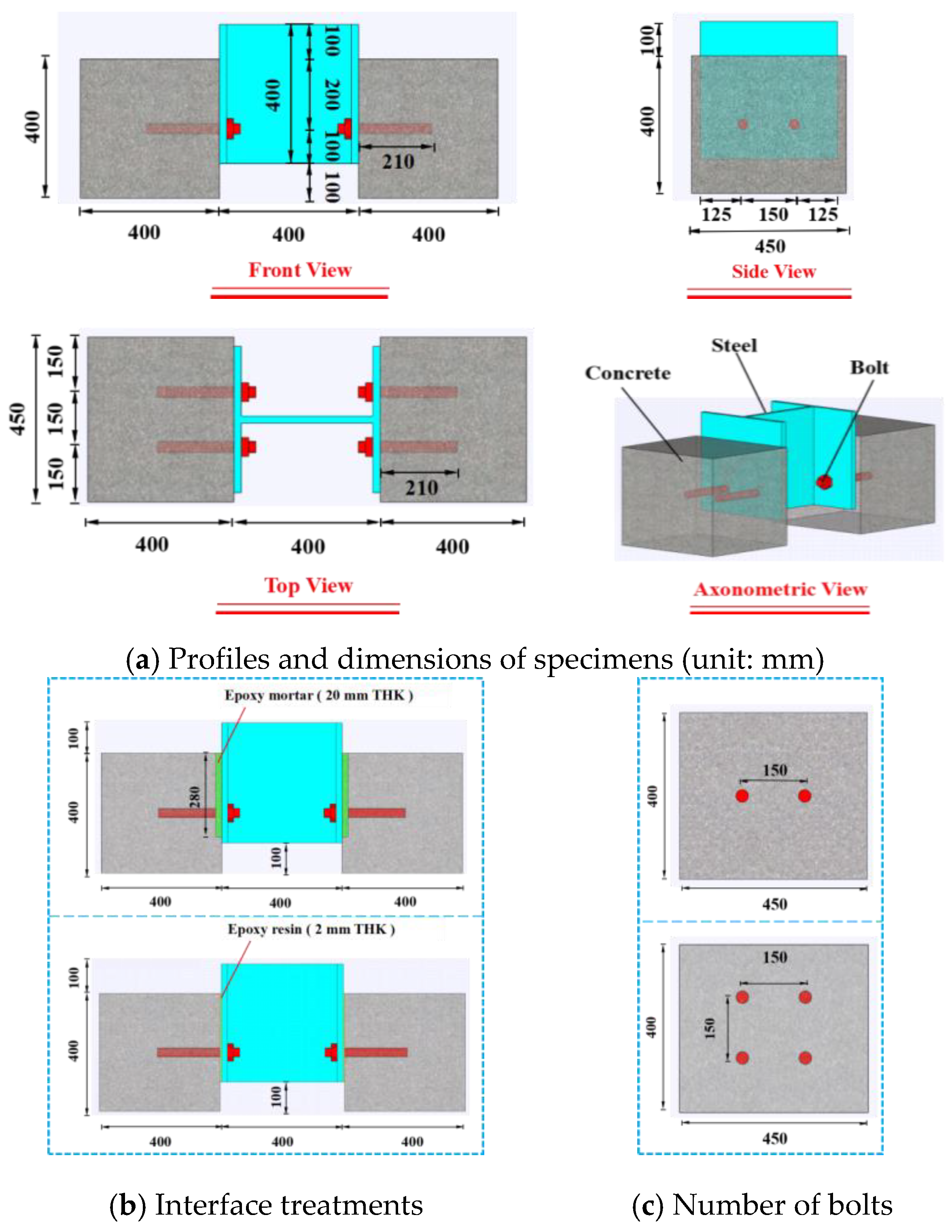
2.1. Specimen Design

Four push-out tests were conducted in this study. The dimensions of the specimens referred to those recommended in Eurocode 4 (EC 4) [49], as depicted in Figure 3a. All of the specimens had an identical geometrical profile, and consisted of one H-shaped steel block and two concrete blocks. The H-shaped steel block represented the steel component in the ASSJ, and the concrete blocks were analogous with the SCP. The H-shaped steel block was 400 mm high, with a cross-section of HW 400 × 400 (19 mm web and 21 mm flange). The concrete block was 400 mm wide, 400 mm high, and 450 mm thick.
The experimental parameters included surface treatment and bolt number as presented in Table 1. The first specimen was designed as a barely roughened surface treatment between steel and concrete. The surface of the second specimen was smeared with epoxy resin. In the third and the fourth specimens, slots with 380 mm width, 280 mm height, and 20 mm depth were reserved, which would be filled by high-performance epoxy mortar as shown in Figure 3b. The front three specimens employed four bolts for connections between concrete and steel, while the fourth specimen used eight bolts as shown Figure 3c. A gap of 100 mm was maintained between the bottoms of the concrete blocks and the H-shaped steel block to accommodate the slippage between the H-shape steel and concrete blocks.
The specimen nomenclature comprised three parts. The first part, R, E, and M20, represented a surface treatment of “barely rough”, “rough and epoxy resin”, and “rough and epoxy mortar”, respectively. The second part, B30, meant bolts with a 30 mm diameter. The last digit represented the bolt row.

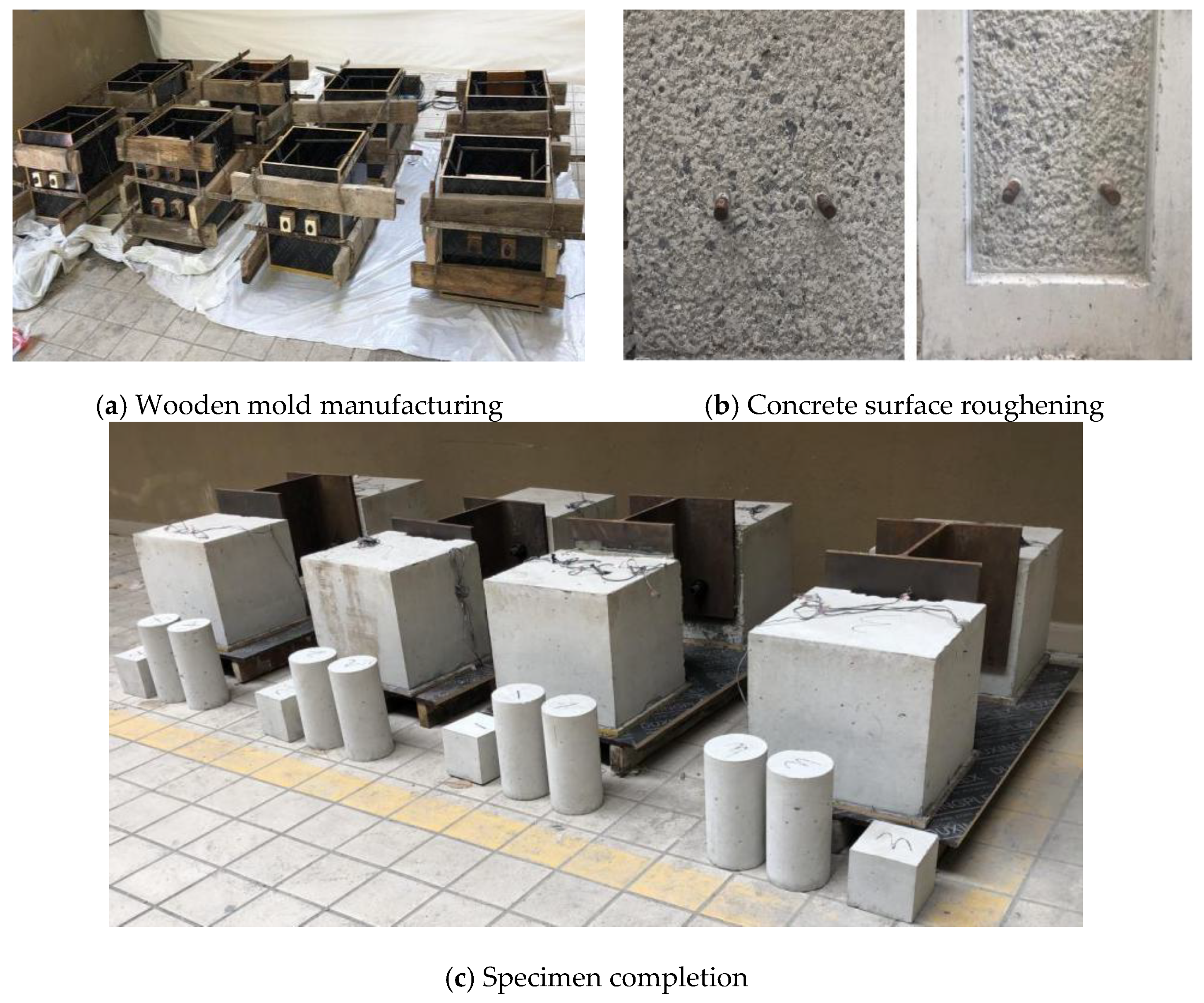
2.2. Specimen Fabrication

The manufacturing process of the specimens is illustrated in Figure 4. In the practical rehabilitation projects, the bolts were post-installed into the SCP. In order to simplify the experimental operation, the bolts were pre-embedded in the wooden mold of the concrete; then, the concrete block was cast as shown in Figure 4a. Concrete blocks of the specimens were cured under wet conditions for two weeks. All concrete block surfaces were roughened as shown in Figure 4b. The steel plates and bolts of specimen R-B30-1 were directly fastened to the concrete blocks. Specimen E-B30-1 was smeared in advance with epoxy resin at the roughened surface of the concrete block. After the steel was added to the concrete blocks, the bolts were tightened with a torque of 300 kN·m using a calibrated torque wrench to ensure proper pre-tensioning, based on practical engineering requirements. For specimens M20-B30-1 and M20-B30-2, the high-performance epoxy mortar was poured into the reserved slots of the concrete blocks after assembling the steel and bolts. After the epoxy mortar was poured into the reserved slots, the specimens were kept under ambient conditions for 28 days before testing. The completed specimens are illustrated in Figure 4c. Additionally, the controlled cylinders (φ150 mm × 300 mm) and cubes (150 mm × 150 mm × 150 mm for normal concrete, and 100 mm × 100 mm × 100 mm for epoxy mortar) were fabricated simultaneously, and subjected to curing conditions identical to those of the corresponding specimens.

2.3. Material Properties

The concrete blocks and steel blocks in the specimens were designed analogous to those in engineering practice. The constituents of C40 concrete were 368 kg cement, 640 kg sand, 1138 kg stone, and 217 kg water in each cubic meter, and the expected concrete strength was set at 40 MPa. H-shaped steel blocks adopted Q355 steel, whose nominal yield strength was 355 MPa. The material properties of concrete, H-shaped steel, bolts, and epoxy mortar in the push-out tests were acquired by laboratory tests, while those of epoxy resin were provided by the product supplier. The material properties of concrete and epoxy mortar were examined on the day of specimen testing, including the cubic compressive strength fcu [50], modulus of elasticity Ec [51], and Poisson’s ratio ν [51]. Additionally, tension tests were performed on the bolts and steel in accordance with ASTM A370-14 [52] to obtain the yield strength fy, and ultimate strength fu. The tested yield strength fy and ultimate strength fu of the bolts were 602.41 MPa and 664.23 MPa, respectively. The test results are summarized in Table 2. The material properties of epoxy resin were provided by the manufacturer, with a compressive strength of 122.9 MPa, a tensile strength of 44.2 MPa, and a positive tensile bond strength of 4.4 MPa between steel and concrete.

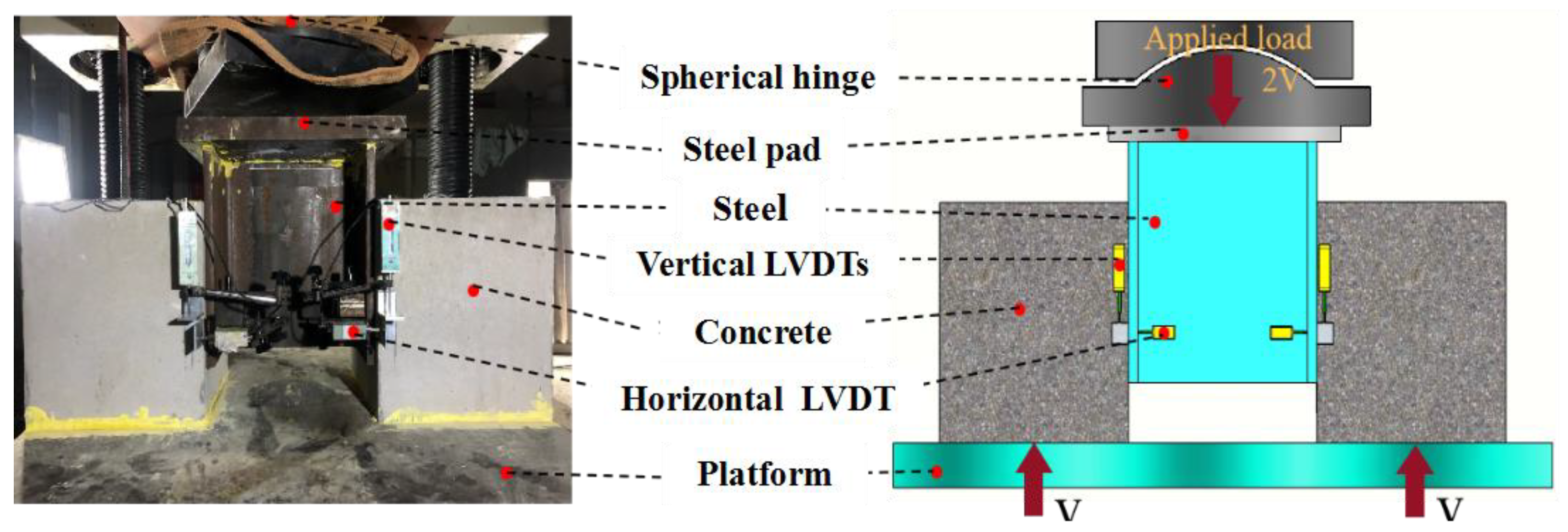
2.4. Test Setup and Instruments

An electro-hydraulic servo loading machine with 5000 kN capacity was employed for the push-out test. To ensure that the H-shaped steel can uniformly bear the vertical force, a spherical seat plate is placed between the machine and the specimen to minimize the possible eccentric moment. As shown in Figure 5, two linear variable displacement transducers (LVDTs) are installed to record the vertical relative slips between the concrete block and the H-shaped steel, while two LVDTs are for horizontal dilatancy. All four LVDTs are installed at a height of 200 mm from the bottom platform, which was located at the height of the single-row bolt.
The loading protocol was classified into two stages, namely the pre-loading stage and the formal stage. During the initial pre-loading stage, a reverse loading and unloading procedure was conducted at a speed of 10 kN/s to ensure the normal operation of the measuring devices. In the formal loading stage, a displacement control loading process was adopted at a speed of 0.3 mm/min. In particular, the crack patterns were observed and recorded at every increment of 0.05 mm. The experiment was terminated when a fracture of the bolts occurred, or the exerting load declined to 80% of the peak load.

3. Test Results and Discussions

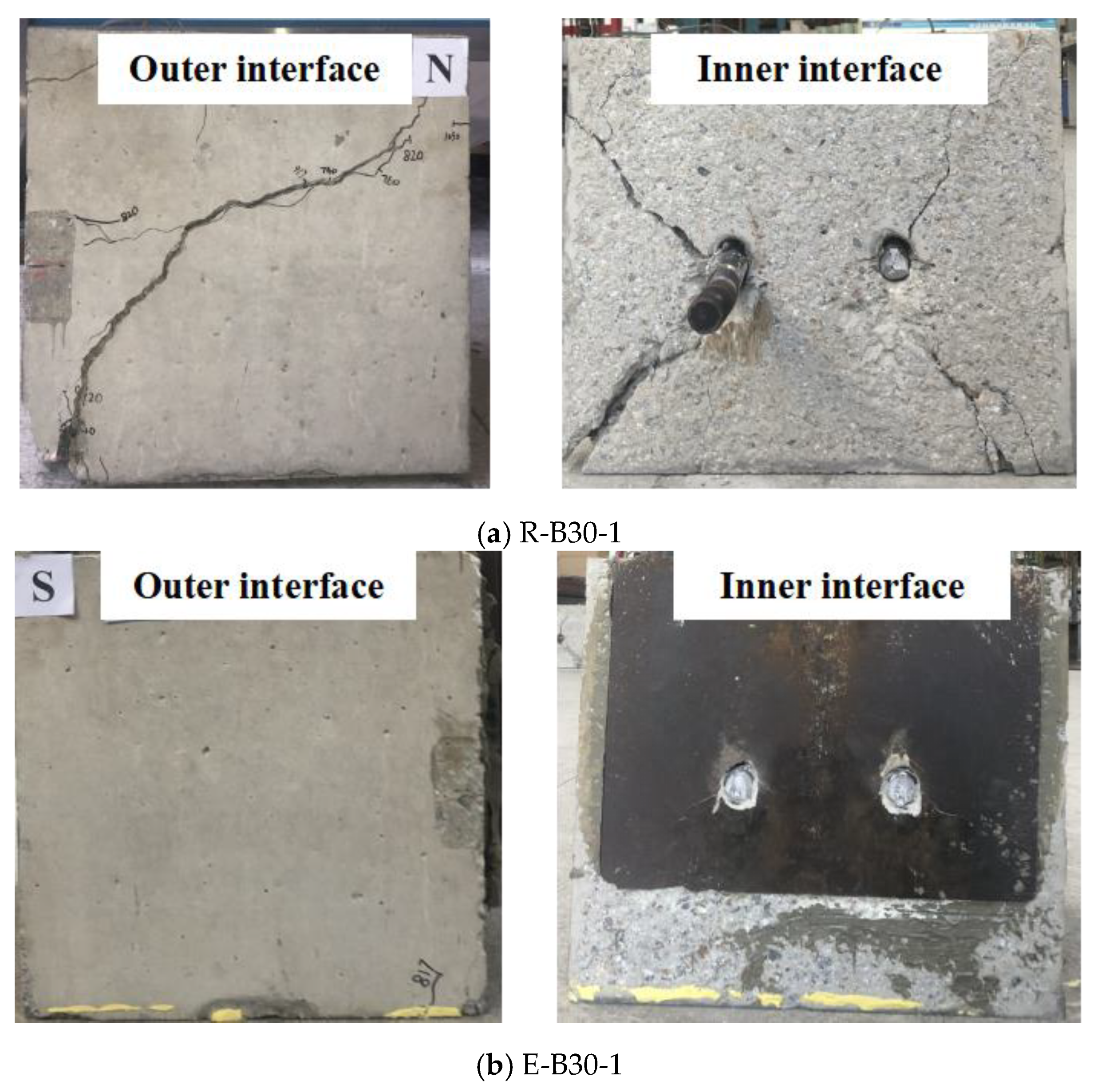
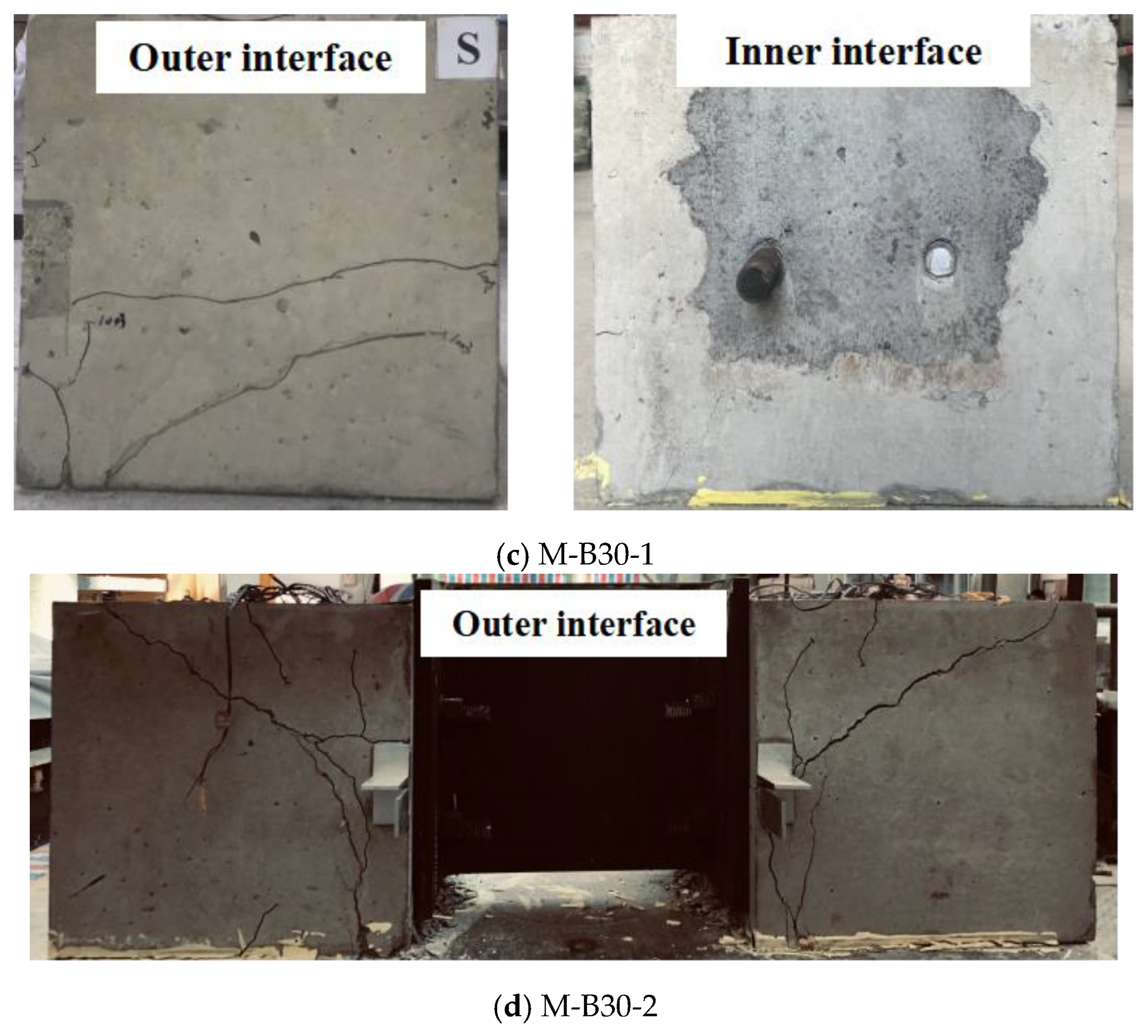
3.1. Observed Phenomena

The cracking patterns are presented in Figure 6, and the ultimate loads, slips at ultimate loads, and failure modes of specimens are also summarized in Table 3.
In general, specimens with different interface treatments exhibited disparate failure modes. As shown in Figure 6a, after initial loading, cracks first appeared at the concrete surface of specimen R-B30-1 at the height of the bolt arrangement. As the load continued to rise, these cracks continued to develop diagonally upwards and downwards, and ultimately penetrated the whole concrete block. When the load reached its peak, the bolts fractured, and cracks sharply increased on the outer surface of the concrete block, causing serious concrete damage. For specimens E-B30-1 and M20-B30-1, before the load reached its peak, no visible cracks or concrete crushing were observed on the outer concrete surface. When the load reached its peak, the bolts were sheared off at the steel–concrete interface, and there were only a few cracks on the inner interface of the concrete, as shown in Figure 6b,c. For the specimen M20-B30-2, with four bolts in a double row as shown in Figure 6d, cracks appeared on the outer concrete surface. When the load reached its peak, the bolts were broken, but the concrete damage was not as severe as the specimen R-B30-1.

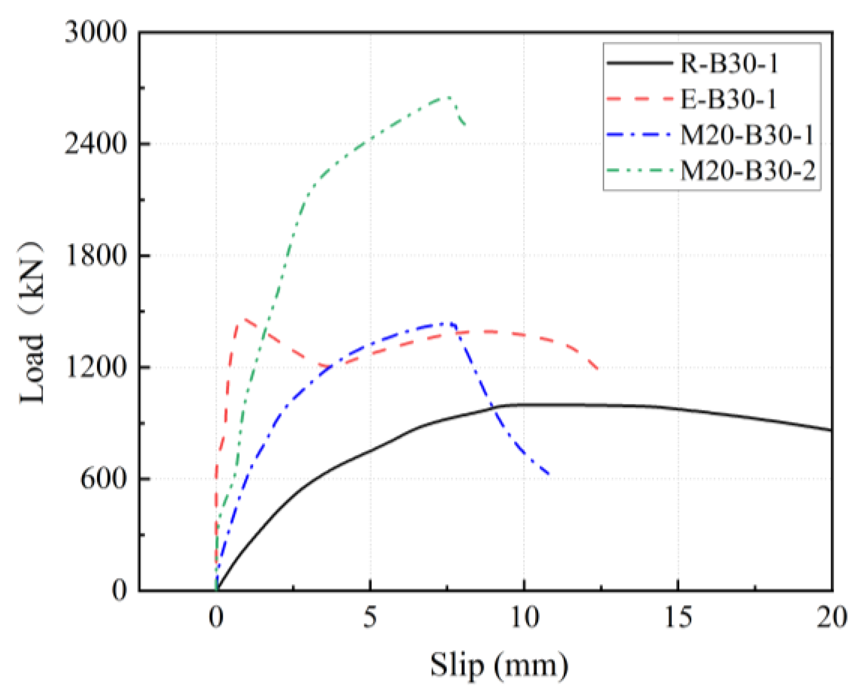
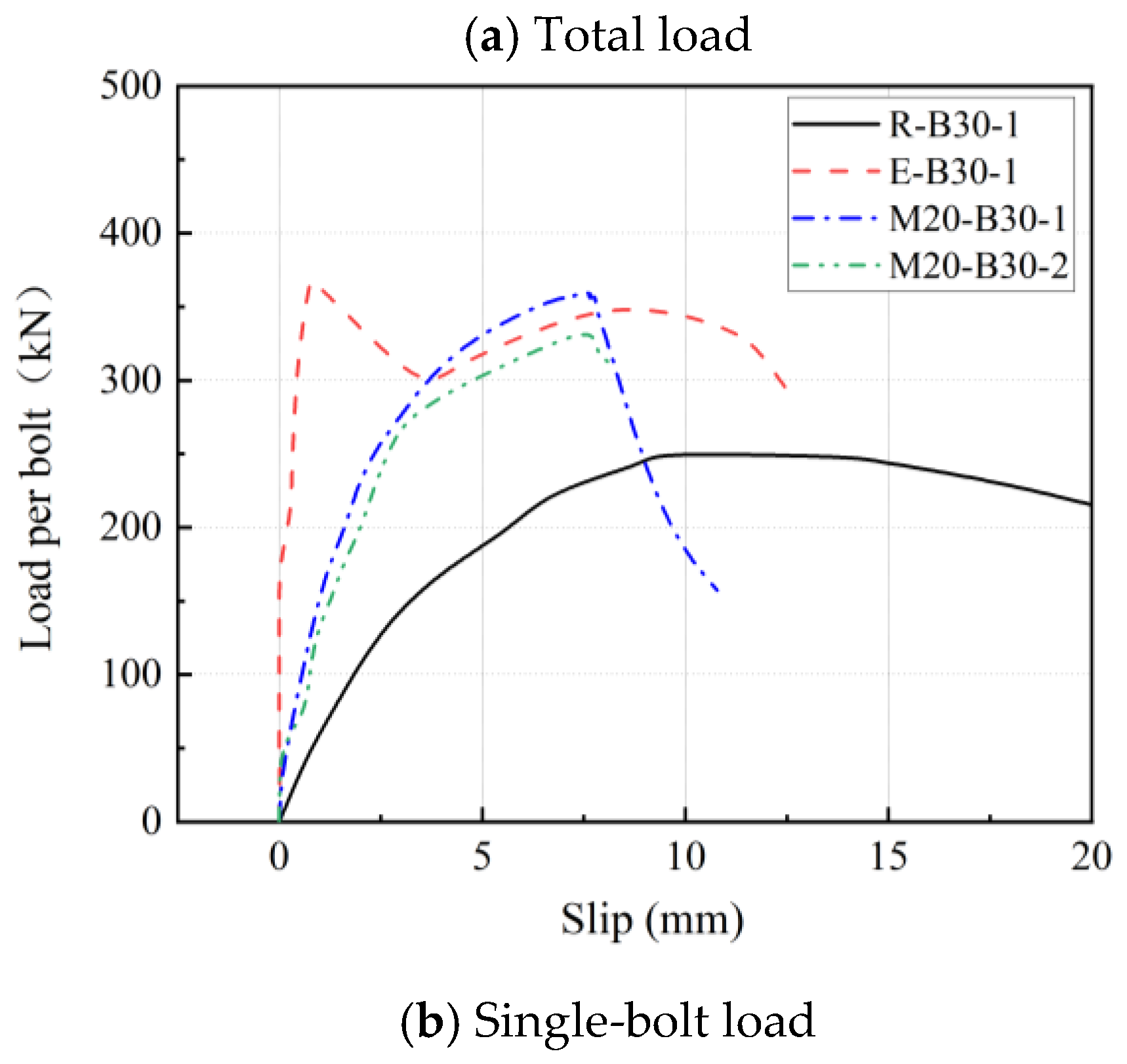
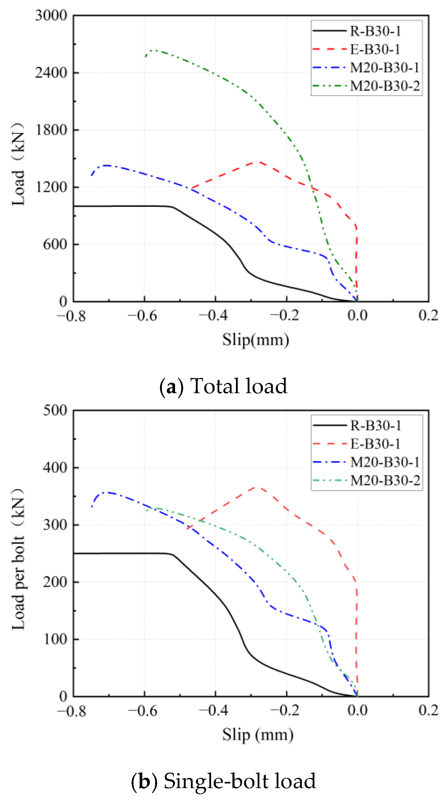
3.2. Load–Slip Relationships

The load–slip curves of the specimens are delineated in Figure 7; Figure 7a illustrates total load–slip curves and Figure 7b depicts single-bolt load–slip curves. The slippages were determined as the average of the two vertical LVDTs. The single-bolt load was obtained by dividing the bolt number by the total load. The load–slip curves can reveal the evolving failure process of the specimens.
Generally, the curves can be divided into three phases, namely, the elastic phase, elastic–plastic phase, and failure phase. During the elastic phase, the deformations of the specimens are relatively small, and the growth slopes of the curves are basically similar. In the elastic–plastic phase, additionally to elastic deformation, some plastic deformation occurs and the stiffness decreases. At this phase, cracks began to appear in the concrete internal surface, and the deformation commenced to increase. With vertical load escalation, the deformation enlarged, and the cracks developed rapidly until the peak load. In the failure phase after the peak load, the load dropped and the relative slip enhanced, due to the bolt fracture or concrete damage.
As shown in Figure 7b, from the single-bolt load–slip curve of specimen R-B30-1, it can be seen that the load-bearing capacity of the steel–concrete interface with bare roughness is the weakest, and the curve was most gentle. Under the prying action of the bolt, the concrete cracked and crushed severely, and the relative slip between the concrete and steel is more pronounced. During the loading process on specimen E-B30-1 with epoxy resin treatment, local adhesive layer peeling occurred. When the adhesive layer failed in the area near the bolt shank, LVDTs detected a significant increase in displacement and a sudden drop in load. The peak of E-B30-1 approaches the highest value, while its ascending curve slope is more precipitous than the others. Compared to the specimen R-B30-1, the peak and ascending slope of the load–slip curve of the specimen M20-B30-1 is relatively moderately higher, indicating that surface treatment of roughness and epoxy mortar can improve the shear strength and shear stiffness of the specimen. The slip at the ultimate load of M20-B30-1 is larger than that of E-B30-1, which prevents brittle failure by filling epoxy mortar. Finally, due to the additional row of bolts, the total load-bearing capacity of specimen M20-B30-2 has significantly improved, but the single-bolt load slightly decreased compared with specimen M20-B30-1.
The slippages at peak loads of R-B30-1, M20-B30-1, and M20-B30-2 were 14.06 mm, 8.23 mm, and 7.77 mm, respectively, which was greater than the 6.0 mm required by EC4 ductility. E-B30-1 recorded the lowest slippage at peak load as 0.78 mm, which indicates poor ductility.

3.3. Load–Dilatancy Curves

The horizontal dilatancies varied with the increasing load, which is delineated in Figure 8. The specimen without a grouting layer (R-B30-1) showed the largest horizontal dilatancy, due to the poor surface treatment of the concrete blocks. In contrast, the dilatancy of the specimen with epoxy resin (E-B30-1) was recorded as the smallest one, while separation occurred suddenly at approximately half of the peak load. The maximum dilatancies of two specimens with epoxy mortar layers lay between those of the previous two specimens.
The dilate separations between steel and concrete were revealed at the initial loading for the specimens without epoxy resin (R-B30-1, M20-B30-1, and M20-B30-2), and continuously escalated with the load increasing. All maximum dilatancies of the specimens were less than 1.0 mm, which can be taken as a negligible value.

3.4. Ultimate Loads

The load-bearing capacity of the bolts on the push-out tests is illustrated in Figure 9. From the comparison of total loads in Figure 9a, the specimen R-B30-1 with barely roughened interface treatment recorded a load-bearing capacity of 1003.85 kN, which was the lowest value. This was mainly attributed to poor surface treatment, which led to the local concrete crushing and the over-deformation of bolts. The specimen E-B30-1 with epoxy resin and specimen M-B30-1 with an epoxy mortar interface had ultimate load-bearing capacities of 1482.86 kN and 1440.14 kN, respectively, which increased by about 48.2% and 44.01% relative to R-B30-1. E-B30-1 and M20-B30-1 exhibited similar load-bearing capacities. The higher load-bearing capacities of E-B30-1 and M20-B30-1 came from the stress alleviation of an epoxy resin or epoxy mortar layer around the bolts, and the failure modes were dominantly bolt fractures. Under the arrangement of two rows of bolts, the total load-bearing capacity of specimen M20-B30-2 significantly improved. However, as shown in Figure 9b, the single-bolt load of M20-B30-2 was slightly reduced relative to M20-B30-1. This was possibly the result of overlapping stress from a group effect or from the uneven stress distribution.
When the epoxy resin was used for the steel–concrete interface treatment in practical engineering, it was difficult to evenly smear the adhesive layer during the construction process, resulting in a compromise of bonding strength at the interface. By comparison, high-performance epoxy mortar could easily fill the steel–concrete gap, enabling it to transmit force more evenly. Therefore, interface treatment with epoxy mortar filling between the steel plates and concrete has greater prospects in engineering applications, and not only features relatively high shear strength, but also excellent ductility and feasible construction.

4. Applicability of Theoretical Formulae

At present, there is no clear specification for the interfacial shear resistance design of a post-anchoring bolt with an epoxy mortar filled layer or smeared epoxy resin. Based on relevant experimental data, several suggested formulae for calculating the shear-bearing capacity of steel bolts for certain applications have been provided in existing literature [53].
The applicability of four mainstream design formulae for conventional shear studs was evaluated using the experimental results, and regarding European code EC 4 [49], American code AASHTO [54], Chinese code GB50017 [55], and Japanese code JSCE [56]. At the same time, the formulae for the shear-bearing capacity of high-strength bolt connections provided by Kwon [7] and Liu [57] are also referenced. The recommended formulae and parameter descriptions are shown in Table 4. For formulae of EC 4, AASHTO, and GB50017, the first item in the formula represents the concrete crushing near the shear connectors, and the second item indicates the shearing off of the shear connectors. The second item also refers to the upper limit of the shear capacity. The formulae of JSCE, Kwon, and Liu adopt only one expression, which does not distinguish the failure modes of concrete crushing and connector failure.
Table 5 lists the calculated shear capacities of the shear connections in this research by six chosen formulae, and compares the experimental results with the calculated results. PE, PA, PG, and PJ represent the calculated results using the formulae in EC4, AASHTO, GB50017, and JSCE, respectively, while Pk and PL refer to the recommended formulae in Kwon and Liu’s literature; PT is the experimental value. In Table 5, when calculating the first items in EC 4, AASHTO, and GB50017, the material properties of normal concrete were adopted as f c = 42.2   MPa   and   E c = 32345   MPa .
From Table 5, the Kwon formula provides the lowest predicted value for shear capacity, and GB50017 presents the highest. The calculated results using EC 4, AASHTO, and GB50017 (241.9 kN, 245.8 kN, and 281.8 kN) originate from the first item which indicates the concrete crushing.
It can also be seen that the test value PT of the specimen with roughened interface treatment (R-B30-1) is greater than the calculated values obtained from the EC 4, AASHTO, Kwon, and Liu formulae, while lower than those of GB50017 and JSCE formulae. EC 4 and AASHTO are recommended for calculating the shear capacity of specimen R-B30-1.
When the interface was treated with epoxy mortar or epoxy resin, it is obvious that the shear capacity will be significantly improved. Therefore, these six formulae are relatively conservative in predicting the shear capacity of shear connectors with an epoxy resin layer or epoxy mortar layer. The Kwon formula gives the most conservative estimation, while the formulae of EC 4, AASHTO, JSCE, and Liu provide similar results of an aspect ratio around 1.40. GB50017 was relatively lower and more accurate due to the calculated results being the closest to the connector failure as revealed by the experimental results. The underestimation of EC 4, AASHTO, and GB50017 formulae can be attributed to the calculated scenario of concrete crushing deviating from the actual failure modes of bolts shearing off for the specimens with an epoxy resin layer or epoxy mortar layer, because of the higher strength and stiffness of surrounding epoxy resin or epoxy mortar.
Regarding the specimens with an epoxy resin layer or epoxy mortar layer, when calculating the first items in formulae of EC 4, AASHTO, and GB50017, if the material properties of epoxy resin or epoxy mortar are adopted in Table 2, the calculated values of the first items will be higher than the second items in the formulae. Thus, the calculated values of the second items will be chosen as the shear capacities of the shear connectors with an epoxy resin layer and epoxy mortar layer, which were listed in parentheses as 298.0 kN, 279.4 kN, and 286.8 kN for EC 4, AASHTO, and GB50017, respectively. The ratios of experimental results to the values calculated by EC 4, AASHTO, and GB50017 formulae were 1.19, 1.27, and 1.23, which was reasonably conservative and more accurate than those by JSCE, Kown, and Liu. The formulae of EC 4, AASHTO, and GB50017 are recommended for predicting the shear capacity of large-diameter bolt connectors with an epoxy mortar layer.

5. Verification of Interfacial Shear-Bearing Capacity of ASSJ Design

In a real rehabilitation project in Guangzhou City China, an ASSJ was added to an existing SCP to enhance the anti-overturning capacity of the bridge. A 2.0 cm gap between the ASSJ and SCP was reserved, and the slot was filled with high-performance epoxy mortar to achieve a better connecting effect. A total of 144 post-anchored bolts with a nominal diameter of 30 mm were arranged on the ASSJ, with 72 bolts on each half of the ASSJ. Thirty-six, eighteen, and eighteen bolts were arranged on the outer surface, the front half of the surface, and the rear half of the surface of the SCP as illustrated in Figure 10.
According to Chinese code JTG 3362-2018 [58], considering the unfavorable overloading of heavy vehicles, under the fundamental combination of load actions, when the partial coefficient of vehicle load effect is enlarged to 3.4, the maximum external load (p = 1780 kN) was employed on one side of the ASSJ in the design of the rehabilitation project.
As the rehabilitation project was built according to Chinese codes, incorporating the previous content, the design formula of GB50017 was chosen for predicting the shear-bearing capacity of large-diameter bolts with epoxy mortar filling treatment. The shear strength of one bolt was calculated as 286.8 kN and is presented in Table 5.
When the ASSJ was subjected to the most unfavorable load on one side, it bore the vertical load and a certain degree of eccentric moment. Therefore, it is necessary to verify the load-bearing capacity of the bolts in the ASSJ under the combined action of interfacial shear force and eccentric moment.
When checking the vertical load-bearing capacity of the ASSJ, only the vertical shear contribution of 36 bolts arrayed on the outer surface of the SCP was incorporated; the vertical load of one bolt was born as 1780/36 = 49.4 kN under the most unfavorable load, which is less than the calculated value of 286.8 kN using the recommended formula, meeting design requirements for vertical load capacity.
When checking the eccentric moment resistance of the ASSJ, only the horizontal shear contribution of 36 bolts in the front surface and the rear surface of ASSJ was considered. The horizontal shear force of every bolt varied with the distance to the rotation center in direct proportion, with the bolts at the farthest row from the rotation center having the maximum horizontal shear force. The anchor bolt arrangement of the ASSJ is shown in Figure 10. The maximum horizontal shear force of the farthest location was calculated as follows:
         y i 2 = 8 × ( 200 2 + 400 2 + 600 2 + 800 2 ) = 9.6 × 10 6 m m 2
           R x , max = M y , max y i 2 = 1780 × 1000 × 800 9.6 × 10 6 = 148 kN
where P u is the shear-bearing capacity of one bolt; y i is the vertical distance from a certain row bolt to the rotation center of the bolt group; and R x , m a x is the maximum horizontal shear force exerted on the farthest bolt under an eccentric moment. From the calculated results, the maximum shear force born by bolts in the front and rear surfaces was 148.0 kN, which is less than the shear strength of one bolt of 286.8 kN. This indicated that the test of eccentric moment resistance was passed.

6. Conclusions

Based on a real rehabilitation project to enhance the overturning resistance of an SCP bridge in Guangzhou City, China, four push-out tests were conducted in this study to explore the interfacial shear performance of large-diameter bolt connections between an ASSJ and SCP, aiming to evaluate the design’s safety. The influences of the interfacial treatment and shear bolt number were investigated. According to the experimental results, the following conclusions are drawn.
(1)
Compared with specimens with barely roughened interfaces, epoxy resin and epoxy mortar employed at the steel–concrete interface can increase the shear-bearing capacity of connections by approximately 47.71% and 43.46%, respectively. The interface treatment method using epoxy mortar can also improve the ductility and stiffness, while the specimen smeared with epoxy resin has excessive stiffness, and the failure mode belongs to brittle failure. The slippage of the specimen smeared with epoxy resin was 0.78 mm at peak load, which was significantly lower than the 8.23 mm slippage of the specimen with the epoxy mortar layer.
(2)
Compared with the specimen with a single row of bolts, the shear-bearing capacity of a single bolt in the specimen with two rows of bolts exhibited approximately an 8% reduction, due to the uneven transmission of stress and concrete overstressing.
(3)
By comparing the relevant formulae for shear connectors with the test value, it is shown that the shear-bearing capacity of high-strength bolt connections calculated by the formulae of EC 4, AASHTO, and GB50017 can accurately predict the shear-bearing capacity of large-diameter bolt connectors with an epoxy resin or epoxy mortar layer. The GB50017 formula was recommended for calculating the shear-bearing capacity of the novel bolt connection in this study.
(4)
Under the most unfavorable load on one side, the maximum vertical and horizontal shear force borne by bolts in the ASSJ of an actual rehabilitation project was 49.4 kN and 148.0 kN, respectively, which is less than the calculated GB50017 formula value of 286.8 kN. The connection design of the ASSJ can meet the requirements of load-bearing capacity under the combined action of vertical load and eccentric moment.
(5)
In future work, the long-term performance of the proposed connection under various environmental conditions (e.g., cyclic loading, temperature variations, and moisture exposure) should be investigated to achieve a comprehensive understanding of the structural behaviors of the proposed novel shear connection. This research would provide valuable insights into the durability and aging behavior of the connection, thereby further enhancing its practical application in bridge rehabilitation projects.

Author Contributions

Conceptualization, H.J., L.Z. and J.H.; Methodology, G.M., C.Z. and L.Z.; Software, C.Z. and S.W.; Validation, L.Z., Q.S. and H.J.; Formal analysis, J.X., P.L., Q.S. and L.Z.; Investigation, H.J., Z.C., S.W., J.H. and L.Z.; Resources, H.J. and L.Z.; Data curation, G.M., C.Z. and S.W.; Writing—original draft preparation, G.M. and C.Z.; Writing—review and editing, L.Z., G.M. and H.J.; Visualization, G.M. and C.Z.; Supervision, J.X., P.L. and Z.C.; Project administration, H.J. and L.Z.; Funding acquisition, H.J. All authors have read and agreed to the published version of the manuscript.

Funding

This research was funded by the National Natural Science Foundation of China with grant numbers 51778150, 52208156 and 52278160.

Data Availability Statement

The original contributions presented in the study are included in the article; further inquiries can be directed to the corresponding authors.

Acknowledgments

This project was undertaken at the Structural Laboratory of Guangdong University of Technology in Guangzhou, China. The authors would like to acknowledge this generous support.

Conflicts of Interest

Author Peisen Li was employed by the company Guangdong Provincial Highway Construction Co., Ltd. Authors Zhenkan Chen and Quan Shi were employed by the company Guangzhou Expressway Operation Management Co., Ltd. The remaining authors declare that the research was conducted in the absence of any commercial or financial relationships that could be construed as potential conflicts of interest.

References

  1. Al-Kheetan, M.J.; Al-Tarawneh, M.; Ghaffar, S.H.; Chougan, M.; Jweihan, Y.S.; Rahman, M.M. Resistance of hydrophobic concrete with different moisture contents to advanced freeze–thaw cycles. Struct. Concr. 2021, 22, E1050–E1061. [Google Scholar] [CrossRef]
  2. Li, P.; Han, P.; Ma, Y.L.; Chen, C.J. Analysis of Accident Mechanism and Reinforcement Measures for Single Column Pier Ramp Bridge. Urban Roads Bridges Flood Control 2016, 2, 78–81 + 10–11. (In Chinese) [Google Scholar]
  3. Wang, F.; Wu, H.Y.; Zhao, R.X. Causes and lessons of bridge collapse accidents in past three years at home and abroad. Urban Roads Bridges Flood Control 2020, 12, 73–76. (In Chinese) [Google Scholar]
  4. Makhaik, R. 4 Loaded Trucks Overturn Defense Bridge in Himachal; Hill Post: Shimla, India, 2010. [Google Scholar]
  5. Zhang, J.; Cheng, H.L. Inspiration from the “12.18” Production Safety Responsibility Accident at the Huahu Interchange of the Shanghai Chongqing Expressway. China Highw. 2022, 20, 20–21. (In Chinese) [Google Scholar]
  6. Xi, C. Design and numerical simulation of adding steel cover beams to curved beam single column piers. Transp. World 2022, 35, 132–135. (In Chinese) [Google Scholar]
  7. Kwon, G.; Engelhardt, M.D.; Klingner, R.E. Behavior of post-installed shear connectors under static and fatigue loading. J. Constr. Steel Res. 2010, 66, 532–541. [Google Scholar] [CrossRef]
  8. Kwon, G.; Engelhardt, M.D.; Klingner, R.E. Experimental behavior of bridge beams retrofitted with postinstalled shear connectors. J. Bridge Eng. 2011, 16, 536–545. [Google Scholar] [CrossRef]
  9. Kwon, G.; Engelhardt, M.D.; Klingner, R.E. Parametric studies and preliminary design recommendations on the use of postinstalled shear connectors for strengthening noncomposite steel bridges. J. Bridge Eng. 2012, 17, 310–317. [Google Scholar] [CrossRef]
  10. Chen, Y.T.; Zhao, Y.; West, J.S.; Walbridge, S. Behaviour of steel–precast composite girders with through-bolt shear connectors under static loading. J. Constr. Steel Res. 2014, 103, 168–178. [Google Scholar] [CrossRef]
  11. Guo, S.Y.; Zhang, X.; Chen, J.Z.; Mou, B.; Shang, H.S.; Wang, P.; Zhang, L.; Ren, J. Mechanical and interface bonding properties of epoxy resin reinforced Portland cement repairing mortar. Constr. Build. Mater. 2020, 264, 120715. [Google Scholar] [CrossRef]
  12. Chen, P.; Li, Y.; Zhou, X.; Wang, H.; Li, J. Study on the Bond Performance of Epoxy Resin Concrete with Steel Reinforcement. Buildings 2024, 14, 2905. [Google Scholar] [CrossRef]
  13. Wang, C.; Fan, Z.; Li, C.; Zhang, H.; Xiao, X. Preparation and engineering properties of low-viscosity epoxy grouting materials modified with silicone for microcrack repair. Constr. Build. Mater. 2021, 290, 123270. [Google Scholar] [CrossRef]
  14. Jiang, H.; Chen, Z.; Fang, Z.; Fang, S.; Tu, W.; Mo, F.; Xie, S.; Liu, J. Rapid hardening high performance concrete (RHHPC) for bridge expansion joints: From material properties to interfacial shear performance. Constr. Build. Mater. 2025, 458, 139638. [Google Scholar] [CrossRef]
  15. Zou, S.; Chen, R.; Wang, H.; Fang, Z.; Qu, C.; Zhang, C. Effect of shear key geometrical dimensions on seismic performance of prefabricated concrete piers with shallow socket connections. Structures 2025, 71, 107975. [Google Scholar] [CrossRef]
  16. Weng, K.F.; Zhu, J.X.; Huang, B.T.; Dai, J.G.; Chen, J.F. Interfacial shear behavior between prefabricated Strain-Hardening Ultra-High-Performance Concrete (SH-UHPC) and cast-in-place concrete. Eng. Struct. 2025, 325, 119405. [Google Scholar] [CrossRef]
  17. Fang, Z.; Hu, L.; Jiang, H.; Fang, S.; Zhao, G.; Ma, Y. Shear performance of high-strength friction-grip bolted shear connector in prefabricated steel–UHPC composite beams: Finite element modelling and parametric study. Case Stud. Constr. Mater. 2023, 18, e01860. [Google Scholar] [CrossRef]
  18. Tu, W.; Ke, Y.; Shen, R.; Jiang, H.; Zhang, S.; Tian, Y.; Cao, Z. Interfacial shear behavior of PBL deeply embedded in UHPC considering end-bearing effect. J. Constr. Steel Res. 2025, 226, 109242. [Google Scholar] [CrossRef]
  19. Xiao, J.; Liu, L.; Zeng, H.; Zhai, K.; Fu, J.; Jiang, H.; Pang, L. Research on the bond performance between glass fiber reinforced polymer (GFRP) bars and Ultra-high performance concrete (UHPC). J. Build. Eng. 2024, 98, 111340. [Google Scholar] [CrossRef]
  20. Ataei, A.; Zeynalian, M.; Yazdi, Y. Cyclic behaviour of bolted shear connectors in steel-concrete composite beams. Eng. Struct. 2019, 198, 109455. [Google Scholar] [CrossRef]
  21. Fang, Z.; Wu, J.; Zhao, G.; Fang, S.; Ma, Y.; Jiang, H. Shear performance and design recommendations of single embedded nut bolted shear connectors in prefabricated steel–UHPC composite beams. Steel Compos. Struct. 2024, 50, 319–336. [Google Scholar]
  22. Xu, Q.; Sebastian, W.; Lu, K.; Yao, Y.; Wang, J. Longitudinal shear performance of lightweight steel-UHPC composite connections based on large-diameter high strength friction-grip bolts. Eng. Struct. 2022, 260, 114220. [Google Scholar] [CrossRef]
  23. Zhou, H.; Zhang, Z.; Wu, C.; Wang, H.; Yang, J.; Zou, Y. Shear performance of high-strength bolt-epoxy bonding composite connector in steel-concrete composite structure. Structures 2024, 61, 106085. [Google Scholar] [CrossRef]
  24. Zhang, L.; Deng, B.; He, B.; Jiang, H.; Xiao, J.; Tian, Y.; Fang, J. Experimental Investigation on Shear Behavior of Non-Stirrup UHPC Beams under Larger Shear Span–Depth Ratios. Buildings 2024, 14, 1374. [Google Scholar] [CrossRef]
  25. Jiang, H.; Zhang, L.; Deng, B.; Gao, X.; Xie, S.; Sha, Z.; Chen, M. The direct shear behavior of the ultra-high performance concrete-filled socket connections between the bridge piers and footings. Structures 2024, 66, 106888. [Google Scholar] [CrossRef]
  26. Chen, X.; Yang, Y.; Xue, Y.; Yu, Y.; Feng, S. Shear behavior of large studs and novel bolted connectors in steel-UHPC composite beams. Structures 2022, 45, 2091–2103. [Google Scholar] [CrossRef]
  27. Pavlović, M.; Marković, Z.; Veljković, M.; Buđevac, D. Bolted shear connectors vs. headed studs behaviour in push-out tests. J. Constr. Steel Res. 2013, 88, 134–149. [Google Scholar] [CrossRef]
  28. Jiang, J.; Zhou, Z.; Wang, H.; Zou, Y.; Zhang, Z.; Liang, H. Shear properties of composite steel plate connectors for prefabricated steel–concrete composite beams. Structures 2023, 58, 105360. [Google Scholar] [CrossRef]
  29. Sithara, K.P.; Shajee, S. Analysis of High Strength Friction Grip Bolted Shear Connectors in Composite Beam Section. Int. J. Innov. Res.Sci. Eng. Technol. 2016, 5, 13382–13387. [Google Scholar]
  30. Dallam, L.N. High strength bolt shear connectors-pushout tests. J. Proc. 1968, 65, 767–769. [Google Scholar]
  31. Luo, J.; Wu, G.; Zhao, G.; Fang, S.; Jiang, H.; Xiao, J. Experimental and numerical analysis on shear performance of single embedded nut bolted shear connectors in prefabricated steel-UHPC composite structures under cyclic loading. Structures 2025, 73, 108446. [Google Scholar] [CrossRef]
  32. Jiang, H.; Fang, H.; Wu, J.; Fang, Z.C.; Fang, S.; Chen, G.F. Push-out tests on demountable high-strength friction-grip bolt shear connectors in steel–precast UHPC composite beams for accelerated bridge construction. Steel Compos. Struct. 2022, 45, 797–818. [Google Scholar]
  33. Xian, B.; Wang, G.; Ma, F.; Fang, S.; Jiang, H.; Xiao, J. Shear performance of single embedded nut bolted shear connectors in precast steel–UHPC composite beams under combined tension-shear loads. Case Stud. Constr. Mater. 2024, 21, e03558. [Google Scholar] [CrossRef]
  34. Ataei, A.; Mahmoudy, S.A.; Zeynalian, M.; Chiniforush, A.A.; Ngo, T.D. Experimental study of innovative bolted shear connectors in demountable cold-formed steel–concrete composite beams. Thin-Walled Struct. 2023, 192, 111116. [Google Scholar] [CrossRef]
  35. Fang, Z.; Fang, H.; Li, P.; Jiang, H.; Chen, G. Interfacial shear and flexural performances of steel–precast UHPC composite beams: Full-depth slabs with studs vs. demountable slabs with bolts. Eng. Struct. 2022, 260, 114230. [Google Scholar] [CrossRef]
  36. Gesoğlu, M.; Güneyisi, E.M.; Güneyisi, E.; Yılmaz, M.E.; Mermerdaş, K. Modeling and analysis of the shear capacity of adhesive anchors post-installed into uncracked concrete. Compos. Part B Eng. 2014, 60, 716–724. [Google Scholar] [CrossRef]
  37. Porcarelli, S.; Shedde, D.; Wang, Z.; Ingham, J.M.; Giongo, I.; Dizhur, D. Tension and shear anchorage systems for limestone structures. Constr. Build. Mater. 2021, 272, 121616. [Google Scholar] [CrossRef]
  38. Mahrenholtz, P.; Eligehausen, R. Post-installed concrete anchors in nuclear power plants: Performance and qualification. Nucl. Eng. Des. 2015, 287, 48–56. [Google Scholar] [CrossRef]
  39. Siamakani, S.Y.M.; Jiradilok, P.; Nagai, K.; Sahamitmongkol, R. Discrete mesoscale analysis of adhesive anchors under tensile load taking into account post-installed reinforcement. Constr. Build. Mater. 2020, 262, 120778. [Google Scholar] [CrossRef]
  40. Epackachi, S.; Esmaili, O.; Mirghaderi, S.R.; Behbahani, A.A.T. Behavior of adhesive bonded anchors under tension and shear loads. J. Constr. Steel Res. 2015, 114, 269–280. [Google Scholar] [CrossRef]
  41. Alhaidary, H.; Al-Tamimi, A.K. Importance of performance certification for post-installed anchors: An experimental assessment. Structures 2021, 29, 273–285. [Google Scholar] [CrossRef]
  42. Ceroni, F.; Darban, H.; Luciano, R. Analysis of bond behavior of injected anchors in masonry elements by means of Finite Element Modeling. Compos. Struct. 2020, 241, 112099. [Google Scholar] [CrossRef]
  43. Berthet, J.F.; Yurtdas, I.; Delmas, Y.; Li, A. Evaluation of the adhesion resistance between steel and concrete by push out test. Int. J. Adhes. Adhes. 2011, 31, 75–83. [Google Scholar] [CrossRef]
  44. Luo, Y.; Li, A.; Kang, Z. Parametric study of bonded steel–concrete composite beams by using finite element analysis. Eng. Struct. 2012, 34, 40–51. [Google Scholar] [CrossRef]
  45. Meaud, C.; Jurkiewiez, B.; Ferrier, E. Steel–concrete bonding connection: An experimental study and non-linear finite element analysis. Int. J. Adhes. Adhes. 2014, 54, 131–142. [Google Scholar] [CrossRef]
  46. Jurkiewiez, B.; Meaud, C.; Ferrier, E. Non-linear models for steel–concrete epoxy-bonded beams. J. Constr. Steel Res. 2014, 100, 108–121. [Google Scholar] [CrossRef]
  47. Larbi, A.S.; Ferrier, E.; Jurkiewiez, B.; Hamelin, P. Static behaviour of steel concrete beam connected by bonding. Eng. Struct. 2007, 29, 1034–1042. [Google Scholar] [CrossRef]
  48. Rauscher, S.; Hegger, J. Modern composite structures made of high performance materials. Compos. Constr. Steel Concr. VI 2008, 19, 691–702. [Google Scholar]
  49. Johnson, R.P.; Anderson, D. Designers’ Guide to EN 1994-1-1: Eurocode 4: Design of Composite Steel and Concrete Structures. General Rules and Rules for Buildings; Thomas Telford: London, UK, 2004. [Google Scholar]
  50. ASTM C1231/C1231M-15; Standard Practice for Use of Unbond Caps in Determination of Compressive Strength of Hardened Cylindrical Concrete Specimens. ASTM International: West Conshohocken, PA, USA, 2015.
  51. ASTM C469/C469M-14; Standard Test Method for Static Modulus of Elasticity and Poisson’s Ratio of Concrete in Compression. ASTM International: West Conshohocken, PA, USA, 2014.
  52. ASTM A370-14; Standard Test Methods and Definitions for Mechanical Testing of Steel Products. ASTM International: West Conshohocken, PA, USA, 2014.
  53. Dai, X.H.; Lam, D.; Saveri, E. Effect of concrete strength and stud collar size to shear capacity of demountable shear connectors. J. Struct. Eng. 2015, 141, 04015025. [Google Scholar] [CrossRef]
  54. AASHTO LRFD. Bridge Design Specifications, 8th ed.American Association of State Highway and Transportation Officials (AASHTO): Washington, DC, USA, 2017. [Google Scholar]
  55. GB 50017-2017; Standard for Design of Steel Structures. Ministry of Housing and Urban-Rural Development of the People’s Republic of China, China Architecture & Building Press: Beijing, China, 2017. (In Chinese)
  56. JSCE. Standard Specifications for Steel and Composite Structures; Japan Society of Civil Engineers (JSCE): Tokyo, Japan, 2007. [Google Scholar]
  57. Liu, X.; Bradford, M.A.; Lee, M.S.S. Behavior of high-strength friction-grip bolted shear connectors in sustainable composite beams. J. Struct. Eng. 2015, 141, 04014149. [Google Scholar] [CrossRef]
  58. JTG 3362-2018; Specifications for Design of Highway Reinforced Concrete and Prestressed Concrete Bridges and Culverts. Ministry of Transport of the People’s Republic of China: Beijing, China, 2017. (In Chinese)
Figure 1. Additional steel supporting joists for solo-column concrete piers.
Buildings 15 01299 g001
Figure 2. Sketch of additional steel supporting joist (unit: cm).
Buildings 15 01299 g002aBuildings 15 01299 g002b
Figure 3. Details of push-out specimens (unit: mm).
Buildings 15 01299 g003
Figure 4. Fabrication procedures of test specimens.
Buildings 15 01299 g004
Figure 5. Test setup and instruments.
Buildings 15 01299 g005
Figure 6. Cracking patterns of specimens.
Buildings 15 01299 g006aBuildings 15 01299 g006b
Figure 7. Load–slip curves.
Buildings 15 01299 g007aBuildings 15 01299 g007b
Figure 8. Load–dilatancy curves.
Buildings 15 01299 g008
Figure 9. Comparison of ultimate loads.
Buildings 15 01299 g009
Figure 10. Bolt arrangement in the ASSJ (unit: cm).
Buildings 15 01299 g010
Table 1. Specimen nomenclature and experimental matrix.
No.Specimen NameConcrete GradeBolt Diameter
D (mm)
Bolt Row/Bolt NumberSurface Treatment MethodSteel Grade
1R-B30-1C40301/4Barely roughQ355
2E-B30-1C40301/4Rough + epoxy resinQ355
3M20-B30-1C40301/4Rough + epoxy mortarQ355
4M20-B30-2C40302/8Rough + epoxy mortarQ355
Table 2. Material properties.
Material TypesCompressive Strength
fcu (MPa)
Elastic Modulus
Ec (MPa)
Poisson’s Ratio
γ
Concrete42.2323450.204
Epoxy mortar94.5388370.237
Material typesCompressive strength
fcu (MPa)
Tensile strength
ftu (MPa)
Bonding strength
fs (MPa)
Epoxy resin122.944.24.4
Material typesYield strength
fy (MPa)
Ultimate Strength
fu (MPa)
Bolt602.41664.23
Steel beam363.29515.03
Table 3. Summary of test results.
SpecimensPu (kN) δ u  (mm)Failure Mode
R-B30-11003.8514.06Bolt fracture and concrete spalling
E-B30-11482.860.78Bolt fracture
M20-B30-11440.148.23Bolt fracture
M20-B30-22654.567.77Bolt fracture and concrete spalling
Note: Pu = peak load; δ u = slip at peak load.
Table 4. Formulae for calculating shear capacity of shear connections.
SourceFormulaParameter
EC4 P u = min 0.29 α d 2 f c E c γ v , 0.8 f u π d 2 4 γ v P u : Ultimate shear-bearing capacity of bolts (N)
d : Nominal bolt diameter (mm)
f c : Concrete compressive strength (MPa)
A s c : Effective cross-sectional area of bolts (mm2)
E c : Elastic modulus of concrete (MPa)
f y : Yield strength of bolts (MPa)
f u : Ultimate strength of bolts (MPa)
H : Bolt depth
α : Aspect ratio factor, taken as 1.0 in this article
: Coefficient, here set as 0.75
γ v : Design safety factor, usually taken as 1.25, here set as 1.0
AASHTO-LFRD P u = 0.5 A s c f c E c A s c f u
GB50017-2017 P u = 0.43 A sc f c E c 0.7 A s c f u f u f y
JSCE P u = 10.32 d H f c ( H / d 5.5 ) 56.4 d 2 f c ( H / d > 5.5 )
Kwon P u = 0.5 A sc f u
Liu P u = 0.66 A sc f u
Table 5. Comparisons between calculation values and experimental results.
SpecimenPE
(kN)
PA
(kN)
PG
(kN)
PJ
(kN)
PK
(kN)
PL
(kN)
PT
(kN)
PT/PEPT/PAPT/PGPT/PJPT/PKPT/PL
R-B30-1241.9
(298.0)
245.8
(279.4)
281.8
(286.8)
261.6186.3245.9250.961.041.020.890.961.351.02
E-B30-1241.0
(298.0)
245.8
(279.4)
281.8
(286.8)
261.6186.3245.9370.721.53
(1.24)
1.51
(1.33)
1.32
(1.29)
1.421.991.51
M20-B30-1241.9
(298.0)
245.8
(279.4)
281.8
(286.8)
261.6186.3245.9360.041.49
(1.21)
1.46
(1.29)
1.28
(1.26)
1.381.931.46
M20-B30-2241.9
(298.0)
245.8
(279.4)
281.8
(286.8)
261.6186.3245.9331.821.37
(1.11)
1.35
(1.19)
1.18
(1.16)
1.271.781.35
AVG (remove R-B30-1)1.46
(1.19)
1.44
(1.27)
1.26
(1.23)
1.361.901.44
STDEV (remove R-B30-1)0.0830.0820.0720.0780.1080.082
COV (remove R-B30-1)0.0570.0570.0570.0570.0570.057
Disclaimer/Publisher’s Note: The statements, opinions and data contained in all publications are solely those of the individual author(s) and contributor(s) and not of MDPI and/or the editor(s). MDPI and/or the editor(s) disclaim responsibility for any injury to people or property resulting from any ideas, methods, instructions or products referred to in the content.

