Article

Theoretical Model for Circular Concrete-Filled Steel Tubes Reinforced with Latticed Steel Angles Under Eccentric Loading

1
College of Urban Construction, Hangzhou Polytechnic, Hangzhou 311402, China
2
Department of Civil Engineering, Hangzhou City University, Hangzhou 310015, China
*
Author to whom correspondence should be addressed.
Buildings 2025, 15(8), 1319; https://doi.org/10.3390/buildings15081319
Submission received: 30 March 2025 / Revised: 12 April 2025 / Accepted: 14 April 2025 / Published: 16 April 2025
(This article belongs to the Section Building Structures)

Abstract

:
Concrete-filled steel tube (CFST) columns reinforced with latticed steel angles (LSA), referred to as CFST-LSA columns, have been widely adopted in practical engineering. Understanding their mechanical behavior under eccentric loading is crucial for ensuring structural safety and performance in engineering applications. Previous experimental studies have demonstrated that the incorporation of steel angles substantially improves both the axial capacity and ductility of CFST-LSA columns. Existing methods for determining the eccentric bearing capacity of CFST-LSA columns primarily rely on the normalized N/Nu-M/Mu interaction curve. However, this approach involves a complex calculation procedure for evaluating the eccentric bearing capacity. To address this limitation, this study proposes a theoretical model based on the limit equilibrium method to predict the eccentric bearing capacity of CFST-LSA columns. The proposed model explicitly integrates fundamental geometric and material parameters, thereby enabling a more efficient and programmable calculation of the eccentric bearing capacity. Comparisons between the proposed model and experimental results show good agreement, with a tested-to-predicted eccentric resistance ratio of 1.085 and a coefficient of variation (COV) of 0.022. The proposed model can serve as a practical calculation method for eccentric loading of CFST-LSA columns, facilitating their application in high-rise buildings and long-span bridges.

1. Introduction

Concrete-filled steel tube (CFST) columns, which consist of an outer steel tube and an inner concrete core, have been increasingly adopted in high-rise buildings and long-span bridge structures throughout North America, Japan, Europe, and China in recent years [1,2,3,4,5,6,7]. CFST columns capitalize on the synergistic benefits of both materials: the steel tube provides lateral confinement to the concrete, thereby enhancing its strength and ductility, while the concrete mitigates the risk of local buckling in the steel tube [8]. Consequently, CFST columns demonstrate superior structural performance characterized by enhanced load-bearing capacity, stiffness, ductility, and energy dissipation efficiency. Additionally, the steel tube serves as formwork during concrete casting, streamlining construction processes and improving efficiency relative to traditional reinforced concrete columns [9,10,11,12,13,14].
As the span of bridges and the height of buildings increase, the cross-sectional dimensions of conventional concrete-filled steel tube (CFST) columns tend to become significantly larger. For instance, the diameter of the CFST column on the first floor of the SEG Plaza in Shenzhen reaches 1600 mm [15]. This enlargement of the cross-section not only increases the risk of void formation during concrete pouring but also compromises the usability of internal space. Utilizing high-strength concrete or high-strength steel represents a potential approach to reducing the size of CFST columns [16,17]. Nevertheless, the application of such materials may enhance the brittleness of CFST columns, thereby negatively impacting the seismic performance of the structure. Fiber-reinforced concrete (FRC) is a composite material produced by incorporating various types of reinforcement fibers into concrete. The addition of fibers significantly enhances the mechanical properties of concrete, including its strength, toughness, ductility, impact resistance, and fatigue performance [18,19]. Consequently, using fiber-reinforced concrete as an infill material for concrete-filled steel tubular (CFST) members represents an effective approach to improving structural ductility and toughness [18,19]. However, applying FRC in CFST structures inevitably increases construction costs, so the decision to employ fiber-reinforced concrete should be made after carefully considering both technical requirements and economic factors.
Introducing longitudinal I-shaped or crossed I-shaped steel stiffeners into conventional CFST columns has been identified as a promising solution for reducing the size of CFST columns [20,21,22,23,24,25]. Experimental and numerical simulation studies [15,26,27] on the axial compressive behavior have demonstrated that this method can improve the axial load-bearing capacity of CFST columns, enabling a reduction in their cross-sectional area. Moreover, the incorporation of internal stiffeners can enhance the ductility and energy dissipation capability of CFST columns under seismic load [28,29,30,31,32,33]. Research by Shi et al. [24] and Wang et al. [34] on the bending properties of circular and square concrete-filled steel tubular (CFST) columns reinforced with I-shaped or crossed I-shaped steel stiffeners has demonstrated that these stiffeners significantly enhance bending strength. Furthermore, the investigations conducted by Wang et al. [35] into the eccentric compression behavior of rectangular concrete-filled steel tubular (CFST) columns reinforced with I-shaped steel members revealed a maximum increase of 42.3% in compressive strength, as well as significant enhancements in residual strength and concrete ductility. Despite the numerous advantages offered by CFST columns with internal I-shaped or crossed I-shaped stiffeners, certain limitations exist: (1) the precise positioning of internal steel stiffeners during construction can be challenging; (2) the flexural capacity of the internal stiffeners is not fully utilized. The CFST columns reinforced with latticed steel angles (CFST-LSA) can serve as an alternative to CFST with inner I-shaped or crossed I-shaped stiffeners due to the following advantages [36]: (1) the steel angles are connected by splice plates, facilitating positioning; (2) the steel angles placed at the corners can effectively increase the moment of inertia, enhancing its bending performance, especially under biaxial moments; (3) the latticed steel angles can be used as scaffolding for workers during construction. Nowadays, the CFST-LSA is adopted in high-rise buildings and large-span bridge columns. For instance, a 370-m-tall electric transmission line tower in Zhejiang Province, China, utilized CFST-LSA components, achieving significant economic benefits [37,38,39].
As for the mechanical behavior of the CFST-LSA component, the axial compressive behavior of CFST-LSA columns has been investigated by Xu et al. [37,38,39], while the bending behavior of CFST-LSA beams has been studied by Hu et al. [40] and Wang et al. [41]. The research results indicate that the latticed steel angles form a secondary confining effect on the surrounded concrete, and the steel angles significantly enhance both the axial compression capacity and the bending strength. Recognizing that ideal axial compression columns do not exist in practical applications, the eccentric compression tests on CFST-LSA columns were conducted, and the normalized N/Nu-M/Mu interaction curve was proposed by Chen et al. [36]. In the research proposed by Chen et al. [36], the normalized N/Nu-M/Mu interaction curve was primarily developed based on the fitting results of the finite element simulations. Therefore, the accuracy and reliability of the proposed N/Nu-M/Mu correlation curve require further validation and analysis to confirm its reliability.
To date, several researchers have proposed theoretical models for predicting the load-bearing capacity of concrete-filled steel tubes (CFST) or strengthened CFST members under eccentric loading conditions. For instance, Du et al. [42] developed a theoretical model for calculating the eccentric bearing capacity of circular CFST columns by introducing a stability parameter. Ran et al. [43] established an analytical model for the eccentric bearing capacity of circular CFST columns strengthened with textile-reinforced mortar (TRM) using the fiber model method. Similarly, Zeng et al. [44] proposed a theoretical model for calculating the eccentric bearing capacity of circular CFST columns strengthened by PET-FRP based on the fiber model method. Gao et al. [45] introduced a theoretical model for predicting the eccentric bearing capacity of square CFST columns strengthened with CFRP. Furthermore, Yan et al. [46] presented a theoretical calculation model for the eccentric bearing capacity of circular CFST columns filled with ultra-high-performance fiber-reinforced concrete (UHPFRC). Correspondingly, several scholars have developed theoretical calculation models to evaluate the eccentric compressive bearing capacity of concrete-filled steel tubes (CFST) with stiffeners. For instance, Hu et al. [47] proposed a theoretical model for analyzing the eccentric compression behavior of square CFST reinforced with internal spirals. Ahmed et al. [48] introduced a theoretical model for assessing the eccentric compressive bearing capacity of circular CFST reinforced with circular steel tubes using the fiber model approach. However, the theoretical model for evaluating the eccentric compressive capacity of CFST-LSA members has not been reported in the literature up to now. This paper thus proposes a theoretical model for predicting the compressive bearing capacity of CFST-LSA columns under eccentric compression. The model is based on existing test data and reasonable assumptions, as well as considering the different failure modes of columns at varying eccentricities.

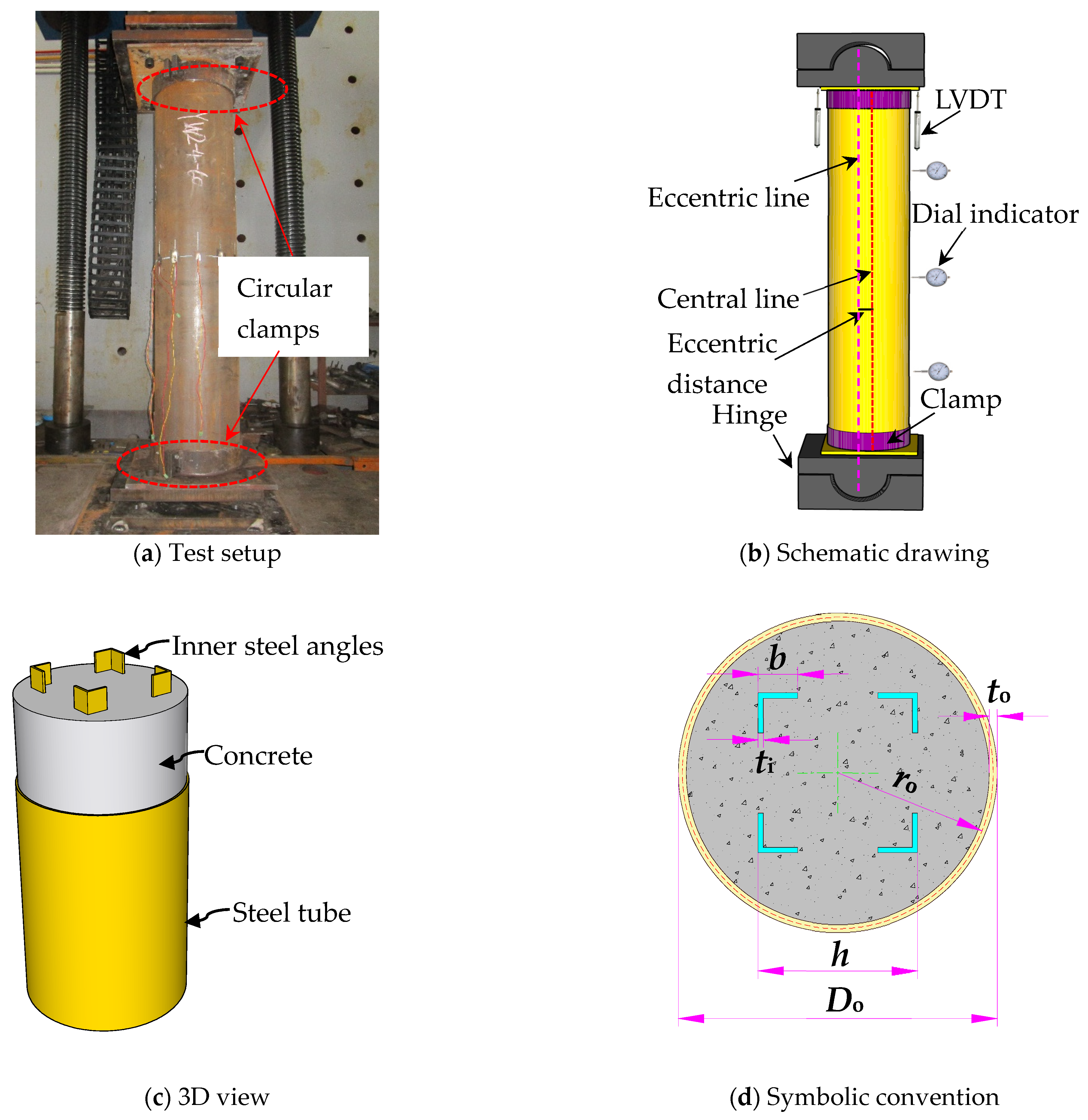
2. Summary of Eccentric Compression Tests of CFST-LSA

The proposed CFST-LSA under an eccentric compression load was experimentally investigated by Chen et al. [36]. Figure 1 illustrates the layout of the experimental setup and measurement instruments provided in reference [36]. The eccentrically loaded specimens were subjected to loading with both ends hinged. The eccentric distance e0 was achieved by offsetting the centerline of the specimen from the line connecting the center of the loading head of the testing machine and the center of the bottom spherical hinge. To prevent the occurrence of local buckling failure modes at the ends of the specimens, circular clamps were installed at both ends of all eccentrically loaded specimens.
The dimensions of the components in CFST-LSA are listed in Table 1. The length of all specimens is 2000 mm, with an outer steel tube diameter of 400 mm and a thickness of 4 mm. Based on the eccentric distance (i.e., e0 = 30 mm or e0 = 60 mm), the specimens were divided into two groups. A control test was set up in each group to investigate the effect of the presence of angle steel and its dimensions on the specimens’ load-carrying capacity. The dimensions of the two types of angle steel were L-40 × 4 in mm and L-50 × 6 in mm, with a spacing of 200 mm from the outer edge of the angle steel. To reduce measurement errors, corresponding repeated specimens were set for each group of specimens.

3. Proposed Theoretical Model for Axial Compression Resistance of CFST-LSA

According to the studies by Zhao [49] and Liu [50] on concrete-filled circular and square steel tubes reinforced with I-shaped steel sections, the following conclusions can be drawn: (1) The failure mode of eccentrically loaded concrete-filled steel tube columns with inner steel sections is influenced by the position of the neutral axis; (2) Stub columns of concrete-filled steel tube columns with inner steel sections primarily exhibit strength-based failure, which is characterized by the crushing of concrete in the compression zone. Based on previous theoretical and experimental studies [49,50,51,52], the ultimate limit state is defined as the point where the concrete in the compression zone reaches its compressive strength. Under this assumption, the position of the neutral axis can be classified into two cases: one where it passes through the outer steel tube and one where it does not. In addition, partial yielding occurs in the tension zones of the outer steel tube and the internal steel section. Therefore, the failure modes of the CFST-LSA can be divided into four types based on the stress state of the lower flange of the internal steel angles, as detailed in Table 2. In this situation, the following assumptions are proposed for the calculation of the axial compression resistance of CFST-LSA under eccentrical loading: (1) The tensile contribution of concrete is neglected; (2) Plane section assumption is used for strain distribution; (3) The longitudinal compressive deformation of the CFST-LSA is neglected, and local buckling of the outer steel tube and internal steel angles is not considered; (4) The yield strains of the outer steel tube and the internal steel angles are identical and the steel material follows an elastoplastic constitutive model.

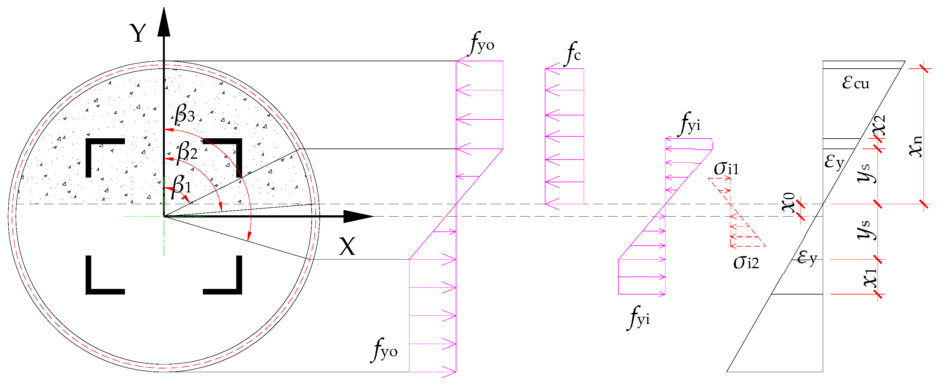
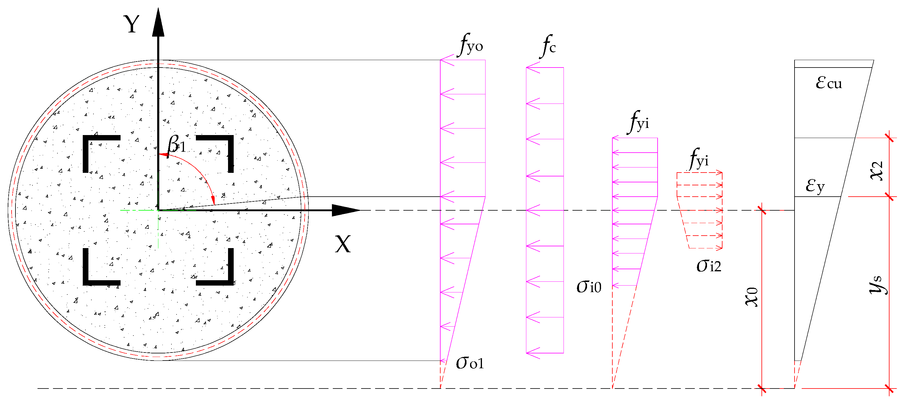
3.1. Case I: Outer Steel Tube and Inner Steel Angles Partially Yield

Figure 2 illustrates the ultimate state of the CFST-LSA in the Case I failure mode. It can be seen that the neutral axis passes through the outer steel tube, and both the tensile and compressive regions of the outer steel tube and internal steel angles partially yield. The concrete reaches its compressive strength. This failure mode is applicable for CFST-LSA with a large eccentricity. The resultant force of the compressive stress in concrete can be expressed as follows:
N c = A c f c = 1 2 ( 2 β 2 sin 2 β 2 ) ( R o t o ) 2 f c
where β2 is the angle corresponding to the neutral axis; Ro and to denote the diameter of the outer steel tube and wall thickness, respectively. fc is the cylinder compressive strength of concrete. In this case, the resultant moment of the compressive stress in concrete about the X-X axis can be written as follows:
M c = 1 2 ( 2 β 2 sin 2 β 2 ) ( R o t o ) 2 f c · 4 sin 3 β 2 · ( R o t o ) 3 ( 2 β 2 sin 2 β 2 ) = 2 3 sin 3 β 2 · ( R o t o ) 3 · f c
For the outer steel tube, the expression for the stress at any point on the steel tube (with compression taken as positive) is as follows:
σ s =   f yo 0 < β β 1 r o cos β x 0 r o cos β 1 x 0 · f yo β 1 < β β 3 f yo β 3 < β π
In Equation (3), fyo is the yield strength of the outer steel tube; β1 and β3 are the angles corresponding to the initial yield point of the outer steel tube in the compressive and tensile regions, respectively; x0 represents the distance between the neutral axis and the centroidal axis of the section; ro is the radius of the inner steel tube. Therefore, the resultant force and the moment about the X-X axis of the stress in the steel tube can be obtained in Equations (4) and (5), respectively:
N uo = 2 0 π σ s d A s       = 2 0 β 1 f yo r o t o d β + 2 β 1 β 3 r o cos β x 0 r o cos β 1 x 0 · f yo r o t o d β + 2 β 3 π ( f yo ) r o t o d β       = 2 r o t o f yo β 1 + β 3 π + r o ( sin β 3 sin β 1 ) x 0 ( β 3 β 1 ) r o cos β 1 x 0
M uo = 2 0 π σ s Y d A s = 2 0 π σ s · r o cos β · r o t o d β       = 2 0 β 1 r o 2 t o f yo cos β d β + 2 β 1 β 3 r o cos β x 0 r o cos β 1 x 0 · r o 2 t o f yo cos β d β 2 β 3 π r o 2 t o f yo cos β d β       = 2 r o 2 t o f yo sin β 1 + sin β 3 + r o ( β 3 β 1 2 + sin 2 β 3 sin 2 β 1 4 ) x 0 ( sin β 3 sin β 1 ) r o cos β 1 x 0
For the inner steel angles, the resultant force and moment about the X-X axis of the stress in the compressive and tensile regions can be calculated based on the stress state of its flanges and webs. In the compressive region, the resultant force Nu1 and moment Mu1 of the yield flange can be obtained in Equations (6) and (7):
Nu1 = 2bti·fyi
M u 1 = N u 1 · ( h t i 2 )
where fyi is the yield strength of the inner steel angles; h is the distance between the outermost edges of the two steel angles; b and t represent the width and thickness of the single steel angle, respectively. The resultant force Nu2 and moment Mu2 of the yield web can be obtained in Equations (8) and (9):
Nu2 = (x2ti)2ti·fyi
M u 2 = N u 2 · ( x 2 t i 2 + y s + x )
where ys is the distance from the neutral axis to the yield point in the tensile or compressive region of the inner steel angles; x2 is the yield height of the steel angles in the compressive region. The resultant force Nu3 and moment Mu3 of the elastic web can be obtained in Equations (10)–(13):
N u 3 = N a N b = ( y s · 2 t i · 1 2 f yi ) ( h 2 b x 0 ) · 2 t i · 1 2 σ i 1
N a = y s t i f yi ;   N b = ( h 2 b x 0 ) t i σ i 1
σ i 1 = ( h 2 b x 0 ) f yi y s
M u 3 = N a ( 2 3 y s + x 0 ) N b 2 3 ( h 2 b x 0 ) + x 0
where σi1 is a virtual stress of the elastic web in the compressive region. Similarly, in the tensile region, the resultant force Tu1 and moment M u 1 of the yield flange are illustrated in Equations (14) and (15):
Tu1 = 2bti·fyi
M u 1 = T u 1 ( h t i 2 )
The resultant force Tu2 and moment M u 2 of the yield web are obtained by Equations (16) and (17):
Tu2 = (x1ti)2ti·fyi
M u 2 = T u 2 ( x 1 t i 2 + y s x 0 )
The resultant force Tu3 and moment M u 3 of the elastic web are shown in Equations (18)–(21):
T u 3 = T a T b = ( y s · 2 t i · 1 2 f yi ) ( h 2 b + x 0 ) · 2 t i · 1 2 σ i 2
T a = y s t i f yi ;   T b = ( h 2 b + x 0 ) t i σ i 2
σ i 2 = ( h 2 b + x 0 ) f yi y s
M u 3 = T a ( 2 3 y s x 0 ) T b 2 3 ( h 2 b + x 0 ) x 0
where σi2 is a virtual stress of the elastic web in the tensile region. Therefore, the total resultant force Ni and moment Mi can be obtained as follows:
Ni = Nu1 + Nu2 + Nu3Tu3Tu2Tu1
M i = M u 1 + M u 2 + M u 3 + M u 3 + M u 2 + M u 1
In summary, the calculation equations for the normal section resistance of eccentrically compressed CFST-LSA can be obtained as follows:
N = Nc + Nuo + Ni
M = N·e0 = Mc + Muo + Mi
It should be noted that the failure mode Case I needs to satisfy the following: (1) the neutral axis does not exceed the bottom of the upper flange of the steel angles; (2) the lower flange of the steel angles is fully tensioned and yields. The two conditions can be illustrated by Equations (26) and (27):
x 0 h 2 t i
( R o t o ) α sc ( h 2 t i ) 1 + α sc x 0

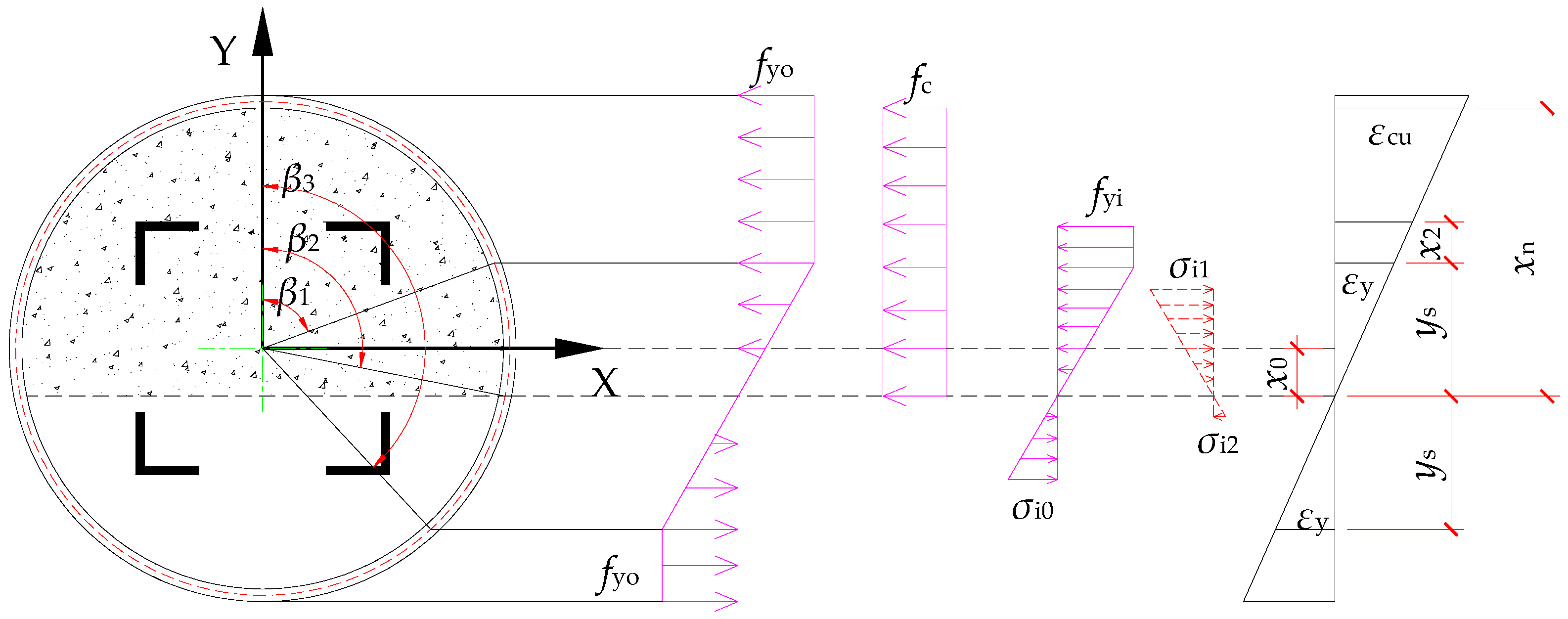
3.2. Case II: Outer Steel Tube Partially Yield and Inner Steel Angles Remain Elastic

In this case, the neutral axis passes through the outer steel tube and both the tensile and compressive zones of the outer steel tube exhibit partial yielding. The compressive zone of the internal steel angles also undergoes partial yielding while its tensile zone remains elastic. Meanwhile, the concrete reaches its ultimate compressive strength. The specific stress state is illustrated in Figure 3. This failure mode commonly occurs when the member exhibits a relatively large eccentricity. For the infilled concrete, the resultant force of the compressive stress is consistent with Equation (1), and the resultant moment of the compressive stress about the X-X axis is consistent with Equation (2). For the outer steel tube, the expression for the stress at any point on the tube is given as follows (with compression taken as positive):
σ s =   f yo 0 < β β 1 r o cos β + x 0 r o cos β 1 + x 0 · f yo β 1 < β β 3 f yo β 3 < β π
Therefore, the resultant force of the steel tube stress is written as follows:
N uo = 2 r o t o f yo β 1 + β 3 π + r o ( sin β 3 sin β 1 ) + x 0 ( β 3 β 1 ) r o cos β 1 + x 0
The resultant moment of the steel tube stress about the X-X axis can be computed as follows:
M uo = 2 r o 2 t o f yo sin β 1 + sin β 3 + r o ( β 3 β 1 2 + sin 2 β 3 sin 2 β 1 4 ) + x 0 ( sin β 3 sin β 1 ) r o cos β 1 + x 0
The resultant force and moment about the X-X axis of the stress for the internal section can be obtained by a similar method as illustrated in Case I. In the compressive region, the resultant force and moment of the yield flange are identical in Equations (6) and (7), respectively. The resultant force of the compressive stress in the yield web is shown in Equation (8), while its resultant moment can be calculated as follows:
M u 2 = N u 2 · ( x 2 t i 2 + y s x )
The resultant force of the compressive stress in the elastic web can be obtained by Equations (32) and (34):
N u 3 = N a N b = ( y s · 2 t i · 1 2 f yi ) ( h 2 b + x 0 ) · 2 t i · 1 2 σ i 1
N a = y s t i f yi ;   N b = ( h 2 b + x 0 ) t i σ i 1
σ i 1 = ( h 2 b + x 0 ) f yi y s
The resultant moment can be further obtained by Equation (35).
M u 3 = N a ( 2 3 y s x 0 ) N b 2 3 ( h 2 b + x 0 ) x 0
In the tensile region, the internal section remains elastic. The resultant force Tu1 and moment M u 1 of the lower flange can be computed as Equations (36) and (37).
Tu1 = 2bti·σi0
M u 1 = T u 1 ( h t i 2 )
The resultant force Tu2 and moment M u 2 of web are both equal to zero since the web remains elastic. The resultant force Tu3 of the elastic web is written as follows:
T u 3 = T a T b = 2 t i ( h 2 t i x 0 ) · 1 2 σ i 0 2 t i ( h 2 b x 0 ) · 1 2 σ i 2
T a = ( h 2 t i x 0 ) σ i 0 t i ;   T b = ( h 2 b x 0 ) σ i 2 t i
σ i 0 = ( h 2 t i x 0 ) f yi y s ;   σ i 2 = ( h 2 b x 0 ) f yi y s
The resultant moment M u 3 of the elastic web can be further obtained in Equation (41).
M u 3 = T a 2 3 ( h 2 t i x 0 ) + x 0 T b 2 3 ( h 2 b x 0 ) + x 0
The resultant force and moment of the internal section can be obtained by Equations (22) and (23), respectively. In summary, the calculation equations for the normal section resistance of eccentrically compressed CFST-LSA can be obtained in Equations (24) and (25). The Case II failure mode must satisfy two conditions: (1) The internal section does not yield in the tensile region; (2) The height of the compressive yield region in the internal steel angles exceeds the height of the upper flange. These two conditions can be represented by Equations (42) and (43).
h 2 ( R o t o ) α sc 1 + α sc x 0
( R o t o ) α sc ( h 2 t i ) 1 α sc x 0 ( R o t o ) α sc ( h 2 b ) 1 α sc

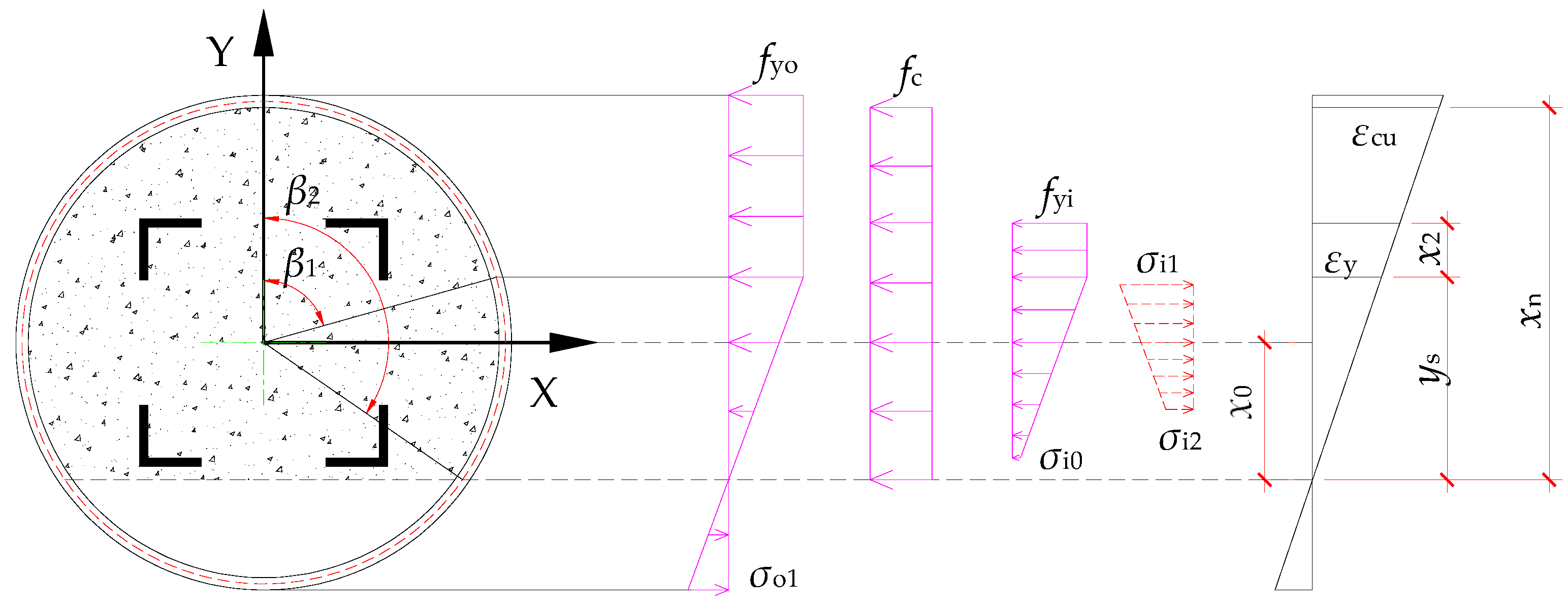
3.3. Case III: Outer Steel Tube and Inner Steel Angles Remain Elastic

In this case, the neutral axis passes through the outer steel tube, with the compressed region of the outer steel tube partially yielding, while the tensile region remains elastic. For the inner steel angles, the compressive region also partially yields, and no tensile region is present. The concrete reaches its ultimate compressive strength. The specific stress state is illustrated in Figure 4. This failure mode commonly occurs when the eccentricity is relatively small.
For the infilled concrete, the resultant force of the compressive stress is consistent with Equation (1), and the resultant moment of the compressive stress about the X-X axis is consistent with Equation (2). For the outer steel tube, the expression for the stress at any point on the tube is given as follows (with compression taken as positive):
σ s =   f yo 0 < β β 1 r o cos β + x 0 r o cos β 1 + x 0 · f yo β 1 < β π
Therefore, the resultant force of the stresses in the steel tube can be written as:
N uo = 2 r o t o f yo β 1 + x 0 ( π β 1 ) r o sin β 1 r o cos β 1 + x 0
The resultant moment of the stresses in the steel tube about the X-X axis can be expressed as follows:
M uo = 2 r o 2 t o f yo sin β 1 + r o ( π β 1 2 sin 2 β 1 4 ) x 0 sin β 1 r o cos β 1 + x 0
The resultant force and moment about the X-X axis of the stress for the internal section can be obtained by a similar method as illustrated in Case I. In the compressive region, the resultant force and moment of the yield flange are identical in Equations (6) and (7), respectively. The resultant force and moment of the compressive stress in the yield web have been calculated by Equations (8) and (31). The resultant force of the compressive stress in the elastic web can be computed as follows:
N u 3 = N a N b
N a = σ i 0 · 2 t i · ( y s x 0 + ( h 2 t i ) ) + 1 2 ( f yi σ i 0 ) · 2 t i · ( y s x 0 + ( h 2 t i ) )
N b = σ i 2 · 2 t i · ( h 2 b ) + 1 2 ( σ i 1 σ i 2 ) · 2 t i · ( h 2 b )
σ i 0 = ( x 0 ( h 2 t i ) ) f yi y s
σ i 1 = ( x 0 + ( h 2 b ) ) f yi y s
σ i 2 = ( x 0 ( h 2 b ) ) f yi y s
The resultant moment Mu3 of the elastic web can be computed as follows:
M u 3 = N a ( σ i 0 + 2 f yi ) · ( y s x 0 + ( h 2 t i ) ) 3 ( σ i 0 + f yi ) ( h 2 t i ) N b ( σ i 2 + 2 σ i 1 ) · ( h 2 b ) 3 ( σ i 2 + σ i 1 ) h 2 b 2
The resultant force Nuo and moment Muo of the elastic compressive stress in the lower flange is written as follows:
Nu0 = 2bti·σi0
M u 0 = N u 0 ( h t i 2 )
Therefore, the resultant force Ni and moment Mi about the X-X axis of the inner section can be obtained by Equations (55) and (66), respectively.
Ni = Nu1 + Nu2 + Nu3Nu0
M i = M u 1 + M u 2 + M u 3 M u 0
In summary, the calculation equations for the normal section resistance of eccentrically compressed CFST-LSA can be obtained in Equations (24) and (25). The Case III failure mode must satisfy the three conditions: (1) The inner steel angles remain compressive, and the neutral axis stays within the inner wall of the steel tube; (2) The tensile side of the steel tube does not undergo yielding; (3) σi0, σi, and σi2 are less than the yield strength of the inner steel angles. These three conditions can be illustrated by Equations (58)–(60), respectively.
h 2 x 0 R o t o
R o ( R o t o ) α sc 1 + α sc x 0
x 0 ( R o t o ) α sc ( h 2 b ) 1 α sc

3.4. Case IV: Neutral Axis Does Not Pass Through the Outer Steel Tube

In this case, the compressive zone of the outer steel tube partially yields, and there is no tensile zone in the outer steel tube. The compressive zone of the internal section also partially yields, and there is no tensile zone in the internal section. The concrete reaches its ultimate compressive strength. The specific stress state is shown in Figure 5. This failure mode commonly occurs when the eccentricity is relatively small.
For the infilled concrete, the central angle β2 = π, the resultant force of the compressive stress in the concrete is:
N c = A c f c = π ( R o t o ) 2 f c
The resultant moment of the compressive stress in the concrete about the X-X axis, Mc = 0, is equal to zero. For the outer steel tube, the expression for the stress at any point on the steel tube (with compression as positive) is consistent with Equation (44). The resultant force of the steel tube stress is consistent with Equation (45). The resultant moment of the steel tube stress about the X-X axis is consistent with Equation (46). The resultant force and moment about the X-X axis of the stress for the internal section can obtained by parts. The resultant force of the yield stress in the upper flange is given by Equation (6) and the resultant moment of the yield stress in the upper flange is given by Equation (7). The resultant force of the yield compressive stress in the web is:
N u 2 = N a N b = x 2 t i · 2 t i · f yi h 2 b 2 ( y s x ) · 2 t i · f yi
In Equation (62), Na and Nb can be computed as follows:
N a = x 2 t i · 2 t i · f yi
N b = h 2 b 2 ( y s x ) · 2 t i · f yi
Therefore, the resultant moment of the compressive yield stress in the web can be expressed as follows:
M u 2 = N a · ( x 2 t i 2 + y s x ) N b · 1 2 ( h 2 b 2 ) 1 2 ( y s x ) + y s x
The resultant force of the elastic compressive stress in the web is:
N u 3 = N a N b
In Equation (66), Na and Nb can be computed as follows:
N a = σ i 0 · 2 t i · ( y s x 0 + ( h 2 t i ) ) + 1 2 ( f yi σ i 0 ) · 2 t i · ( y s x 0 ( h 2 t i ) )
N b = σ i 2 · 2 t i · ( y s x + h 2 b ) + 1 2 ( f yi σ i 2 ) · 2 t i · ( y s x + h 2 b )
The virtual stresses σi0 and σi2 can be expressed as follows:
σ i 0 = ( x 0 ( h 2 t i ) ) f yi y s
σ i 2 = ( x 0 ( h 2 b ) ) f yi y s
Thus, the resultant moment of the elastic compressive stress in the web can be obtained:
M u 3 = N a ( σ i 0 + 2 f yi ) · ( y s x 0 + ( h 2 t i ) ) 3 ( σ i 0 + f yi ) ( h 2 t i ) N b ( σ i 2 + 2 f yi ) · ( h 2 b + y s x ) 3 ( σ i 2 + f yi ) ( h 2 b )
The resultant force Nu0 and moment Mu0 of the elastic compressive stress in the lower flange can be derived as follows:
Nu0 = 2bti·σi0
M u 0 = N u 0 ( h t i 2 )
Therefore, the resultant force Ni and moment Mi about the X-X axis of the inner section can be obtained by Equations (55) and (66), respectively. In summary, the calculation equations for the normal section resistance of eccentrically compressed CFST-LSA can be obtained in Equations (24) and (25). The Case IV failure mode must satisfy the two conditions: (1) the neutral axis is located outside the steel tube and minimum stress on the compressive side of the steel tube does not exceed the yield strength; (2) σi0, σi1, and σi2 are less than the yield strength. The two conditions can be expressed by Equations (74) and (75).
R o x 0 R o + ( R o t o ) α sc 1 α sc
x 0 ( R o t o ) α sc + ( h 2 b ) 1 α sc

3.5. Effect of Second-Order Moment

The above theoretical model is suitable for the CFST-LSA applied in stub columns under eccentric loading.
However, for the calculation of the eccentric capacity of eccentrically compressed slender and medium-length columns, the second-order bending moment caused by the eccentricity and slenderness ratio must be considered. Therefore, an eccentricity amplification factor η needs to be introduced. Based on the study by Liu [50], η can be expressed as follows:
η = 1 + l 0 2 ( 0.003 + f yi / E si + f yo / E so ) 20 e 0 r i ( 1.15 0.01 l 0 2 r i )
Thus, for the calculation of the eccentric capacity of slender and medium-length CFST-LSA columns, e0 in Equation (25) should be replaced by ηe0.

4. Validation of the Theoretical Model for CFST-LSA

To validate the proposed theoretical model for predicting the eccentric capacity of CFST-LSA columns, comparisons were made with existing experimental and numerical results presented by Chen et al. [36]. The test results of Chen et al. [36] demonstrated that the load-bearing capacity decreased more rapidly after reaching the ultimate load compared to the axially compressed specimens, primarily due to excessive lateral displacement induced by eccentricity. Additionally, a corresponding finite element model was developed by Chen et al. [36] to predict the eccentric capacity of CFST-LSA columns.
All experimental and numerical results are provided in reference [36], and the results are listed in Table 3 to compare with the results predicted by the proposed theoretical model. Table 3 presents the test failure modes of CFST-LSA specimens, along with the corresponding failure types determined based on the neutral axis distribution predicted by the theoretical model. As shown in Table 3, all specimens exhibited bending buckling failure during testing. Specimens with an eccentricity of 30 mm experienced failure under Case IV, while those with an eccentricity of 60 mm failed under Case III. Consequently, the steel tube did not undergo tensile yield failure when the tested specimens reached their ultimate bearing capacity.
As shown in Table 3, the proposed theoretical model exhibits relatively conservative predictions when compared with both experimental and numerical results in terms of predicting the eccentric capacity of CFST-LSA columns, with the mean ratio of test values to predicted values being 1.085 and a coefficient of variation of 0.022. The findings were primarily attributed to the eccentricity amplification factor η. Since the second-order effect was considered by introducing the eccentricity amplification factor η, it amplifies the influence of eccentricity on the specimen’s bearing capacity. However, research results from Chen et al. [36] indicate that significant lateral bending effects occur when the specimens reach their ultimate bearing capacity. Consequently, accounting for the eccentricity amplification effect leads to conservative results in the theoretical model calculations presented in this paper.

5. Conclusions

Concrete-filled steel tubes reinforced with latticed steel angle (CFST-LSA) columns have been adopted in practical engineering due to their excellent economic performance. The bearing capacity of such columns under eccentric loading plays a critical role in their design. This paper develops a theoretical model for predicting the bearing capacity of CFST-LSA columns under eccentric loading based on experimental observations and empirical assumptions. Based on the research presented herein, the following conclusions can be drawn:
(1)
According to the four critical states proposed in this paper, the ultimate state of CFST-LSA columns and the position of the neutral axis are closely related to the magnitude of the eccentricity.
(2)
The contribution of the steel angles to the eccentric capacity of CFST-LSA columns under eccentric loading conditions is relatively limited.
(3)
The proposed theoretical model offers relatively conservative predictions for the experimental and numerical outcomes regarding the eccentric capacity of CFST-LSA columns; the average ratio of experimental results to predicted values is 1.085, with a coefficient of variation of 0.022.
(4)
Specimens with an eccentricity of 30 mm experienced failure under Case IV, while those with an eccentricity of 60 mm failed under Case III; hence, the steel tube did not undergo tensile yield failure when the tested specimens reached their ultimate bearing capacity.

Author Contributions

Conceptualization, Z.L. and J.W.; Methodology, Z.L. and J.W.; Software, Z.L. and J.W.; Validation, Z.L. and J.W.; Formal analysis, Z.L. and J.W.; Investigation, Z.L. and J.W.; Resources, Z.L. and J.W.; Data curation, J.W.; Writing—original draft, J.W.; Writing—review & editing, J.W.; Visualization, J.W.; Supervision, J.W.; Project administration, J.W.; Funding acquisition, J.W. All authors have read and agreed to the published version of the manuscript.

Funding

This work was supported by the National Natural Science Foundation of China [grant number: 51908016].

Data Availability Statement

The original contributions presented in the study are included in the article, further inquiries can be directed to the corresponding author.

Conflicts of Interest

The authors declare no conflict of interest.

Nomenclature

AcThe area of concrete subjected to compressive stress
bWidth of a single steel angle
DoThe outer diameter of the steel tube
e0The eccentric distance
EsiElastic modulus of steel angle
EsoElastic modulus of steel tube
fcCylinder compressive strength of concrete
fyiYield strength of steel angle
fyoYield strength of steel tube
hSpacing between the outer edge of two steel angles
L0Total length of specimen
l0Effective length of specimen
McBending moment of concrete in the compression zone about the section centroid axis
MiBending moment of the steel angles about the section centroid axis
MuoBending moment of outer steel tube about the section centroid axis
NcResultant force of concrete in the compression zone
NexpExperimental value of the eccentric compressive capacity
NiResultant force of steel angles
NpCalculated value of the eccentric compressive capacity using the proposed theoretical model
NuoResultant force of steel tube
riRadius of rotation for the cross-sectional profile of the specimen
roThe radius of the central region of the steel tube wall
RoThe radius of the outer edge of steel tube wall
tiThickness of a single steel angle
toWall thickness of steel tube
x0Distance between the neutral axis and the section centroid axis
x1The height of the yield zone of the steel angles in the tension region
x2The height of the yield zone of the steel angles in the compression region
xnDistance between the section centroid axis and the maximum compressive strain of concrete
ysThe height of the unyielded region of the steel angles located in the tension or compression zone
αscThe ratio between the yield strain of steel and the ultimate compressive strain of concrete, αsc = εy/εcu
εcuUltimate compressive strain of concrete
εyYield strain of steel
ηEccentricity amplification factor
σsStress of steel tube

References

  1. Liu, H.Q.; Liu, Y.Z.; Huo, J.S.; Zhu, D.J. Cyclic behaviour of a novel steel beam-to-prefabricated CFST column connection with threaded sleeve bolts. Structures 2021, 34, 615–629. [Google Scholar] [CrossRef]
  2. Hu, H.S.; Wang, H.Z.; Guo, Z.X.; Shahrooz, B.M. Axial Compressive Behavior of Square Spiral-Confined High-Strength Concrete-Filled Steel-Tube Columns. ASCE J. Struct. Eng. 2020, 146, 04020136. [Google Scholar] [CrossRef]
  3. Wang, F.Y.; Young, B.; Gardner, L. Experimental Study of Square and Rectangular CFDST Sections with Stainless Steel Outer Tubes under Axial Compression. ASCE J. Struct. Eng. 2019, 145, 04019139. [Google Scholar] [CrossRef]
  4. Inai, E.; Mukai, A.; Kai, M.; Tokinoya, H.; Fukumoto, T.; Mori, K. Behavior of concrete-filled steel tube beam columns. ASCE J. Struct. Eng. 2004, 130, 189–202. [Google Scholar] [CrossRef]
  5. Yu, Z.W.; Ding, F.X.; Lin, S. Researches on mechanical behavior of high-performance concrete filled tubular steel stub columns after high temperature. J. China Railw. Soc. 2003, 25, 71–79. (In Chinese) [Google Scholar]
  6. Ma, H.; Liu, X.Y.; Chen, Y.C.; Zhao, Y.L. Seismic damage evaluation of steel reinforced recycled concrete filled circular steel tube composite columns. Earthq. Struct. 2022, 23, 445–462. [Google Scholar]
  7. Ding, F.X.; Pan, Z.C.; Lai, Z.C.; Yu, Z.W. Experimental Study on the Seismic Behavior of Tie Bar Stiffened Round-Ended Concrete-Filled Steel Tube Columns. ASCE J. Bridge Eng. 2020, 25, 04020071. [Google Scholar] [CrossRef]
  8. Han, L.H.; An, Y.F. Performance of concrete-encased CFST stub columns under axial compression. J. Constr. Steel Res. 2014, 93, 62–76. [Google Scholar] [CrossRef]
  9. Han, L.H.; Li, W.; Bjorhovde, R. Developments and advanced applications of concrete-filled steel tubular (CFST) structures: Members. J. Constr. Steel Res. 2014, 100, 211–228. [Google Scholar] [CrossRef]
  10. Shen, L.; Yang, B.; Ding, M.; Feng, C.; Alqawzai, S.; Elchalakani, M.; Chen, K. Experimental Study on the Behavior of a Novel Stiffened Hexagonal CFDST Stub Column under Axial Load. ASCE J. Struct. Eng. 2022, 148, 04021231. [Google Scholar] [CrossRef]
  11. Yan, Y.X.; Xu, L.H.; Li, B.; Chi, Y.; Yu, M.; Zhou, K.K.; Song, Y. Axial behavior of ultra-high performance concrete (UHPC) filled stocky steel tubes with square sections. J. Constr. Steel Res. 2019, 158, 417–428. [Google Scholar] [CrossRef]
  12. Zhou, K.; Han, L.H. Experimental and numerical study of temperature developments of composite joints between concrete-encased concrete-filled steel tube columns and reinforced concrete beams. Fire Saf. J. 2020, 116, 103187. [Google Scholar] [CrossRef]
  13. Zhou, K.; Han, L.H. Modelling the behaviour of concrete-encased concrete-filled steel tube (CFST) columns subjected to full-range fire. Eng. Struct. 2019, 183, 265–280. [Google Scholar] [CrossRef]
  14. Zhou, K.; Han, L.H. Experimental performance of concrete-encased CFST columns subjected to full-range fire including heating and cooling. Eng. Struct. 2018, 165, 331–348. [Google Scholar] [CrossRef]
  15. Cai, J.M.; Pan, J.L.; Wu, Y.F. Mechanical behavior of steel-reinforced concrete-filled steel tubular (SRCFST) columns under uniaxial compressive loading. Thin-Walled Struct. 2015, 97, 1–10. [Google Scholar] [CrossRef]
  16. Wei, J.G.; Luo, X.; Lai, Z.C.; Varma, A.H. Experimental Behavior and Design of High-Strength Circular Concrete-Filled Steel Tube Short Columns. ASCE J. Struct. Eng. 2020, 146, 04019184. [Google Scholar] [CrossRef]
  17. Varma, A.H.; Ricles, J.M.; Sause, R.; Lu, L.W. Experimental behavior of high strength square concrete-filled steel tube beam-columns. ASCE J. Struct. Eng. 2002, 128, 309–318. [Google Scholar] [CrossRef]
  18. Shafighfard, T.; Kazemi, F.; Bagherzadeh, F.; Mieloszyk, M.; Yoo, D.Y. Chained machine learning model for predicting load capacity and ductility of steel fiber-reinforced concrete beams. Comput.-Aided Civ. Infrastruct. Eng. 2024, 39, 3573–3594. [Google Scholar] [CrossRef]
  19. Kazemi, F.; Shafighfard, T.; Yoo, D.Y. Data-driven modeling of mechanical properties of fiber-reinforced concrete: A critical review. Arch. Comput. Methods Eng. 2024, 31, 2049–2078. [Google Scholar] [CrossRef]
  20. Zhou, X.H.; Yan, B.; Liu, J.P. Behavior of square tubed steel reinforced-concrete (SRC) columns under eccentric compression. Thin-Walled Struct. 2015, 91, 129–138. [Google Scholar] [CrossRef]
  21. Zhang, S.M.; Li, X.Z.; Li, J.; Lu, W.; Chen, J. Behavior comparison of seven-types of steel-concrete composite stub columns under axial compression. Eng. Struct. 2022, 252, 113637. [Google Scholar] [CrossRef]
  22. Yang, J.L.; Wang, J.Z.; Zhang, S.; Wang, Z.R. Behavior of eccentrically loaded circular CFRP-steel composite tubed steel-reinforced high-strength concrete columns. J. Constr. Steel Res. 2020, 170, 106101. [Google Scholar] [CrossRef]
  23. Qi, H.T.; Guo, L.H.; Liu, J.P.; Gan, D.; Zhang, S.M. Axial load behavior and strength of tubed steel reinforced-concrete (SRC) stub columns. Thin-Walled Struct. 2011, 49, 1141–1150. [Google Scholar] [CrossRef]
  24. Shi, Y.L.; Xian, W.; Wang, W.D.; Li, H.W. Mechanical behaviour of circular steel-reinforced concrete-filled steel tubular members under pure bending loads. Structures 2020, 25, 8–23. [Google Scholar] [CrossRef]
  25. Xu, F.; Wang, J.; Chen, J.; Wang, Y.H. Load-transfer mechanism in angle-encased CFST members under axial tension. Eng. Struct. 2019, 178, 162–178. [Google Scholar] [CrossRef]
  26. Wang, J.; Cheng, X.F.; Yan, L.B.; Wu, C. Numerical study on I-section steel-reinforced concrete-filled steel tubes (SRCFST) under bending. Eng. Struct. 2020, 225, 111276. [Google Scholar] [CrossRef]
  27. Wang, X.D.; Liu, J.P.; Zhou, X.H. Behaviour and design method of short square tubed-steel-reinforced-concrete columns under eccentric loading. J. Constr. Steel Res. 2016, 116, 193–203. [Google Scholar] [CrossRef]
  28. Ma, H.; Qiang, J.Q.; Xi, J.C.; Zhao, Y.L. Cyclic loading tests and horizontal bearing capacity of recycled concrete filled circular steel tube and profile steel composite columns. J. Constr. Steel Res. 2022, 199, 107572. [Google Scholar] [CrossRef]
  29. Xu, C.; Wei, Y.-Y.; Yun, Y.-C. Analysis of steel-reinforced concrete-filled-steel tubular (SRCFST) columns under cyclic loading. Constr. Build. Mater. 2012, 28, 88–95. [Google Scholar]
  30. Liu, J.; Abdullah, J.A.; Zhang, S. Hysteretic behavior and design of square tubed reinforced and steel reinforced concrete (STRC and/or STSRC) short columns. Thin-Walled Struct. 2011, 49, 874–888. [Google Scholar] [CrossRef]
  31. Liu, J.; Li, X.; Zang, X.; Chen, Y.F.; Wang, X. Hysteretic behavior and modified design of square TSRC columns with shear studs. Thin-Walled Struct. 2018, 129, 265–277. [Google Scholar] [CrossRef]
  32. Gan, D.; Guo, L.; Liu, J.; Zhou, X. Seismic behavior and moment strength of tubed steel reinforced-concrete (SRC) beam-columns. J. Constr. Steel Res. 2011, 67, 1516–1524. [Google Scholar] [CrossRef]
  33. Zhou, X.; Liu, J. Seismic behavior and strength of tubed steel reinforced concrete (SRC) short columns. J. Constr. Steel Res. 2010, 66, 885–896. [Google Scholar] [CrossRef]
  34. Wang, W.D.; Wei, X.; Hou, C.; Shi, Y.L. Experimental investigation and FE modelling of the flexural performance of square and rectangular SRCFST members. Structures 2020, 27, 2411–2425. [Google Scholar] [CrossRef]
  35. Wang, Z.B.; Zhang, B.H.; Chen, Z.; Tan, E.L.; Qiu, R.M.; Zheng, T.B. Steel-reinforced concrete-filled rectangular stainless steel tubular columns: Tests, analysis and design. J. Constr. Steel Res. 2025, 226, 109212. [Google Scholar] [CrossRef]
  36. Chen, J.; Hu, L.; Wang, J.; Song, S.S. Eccentric compression behavior of circular concrete-filled steel tubes reinforced with internal latticed steel angles. Struct. Concr. 2024, 25, 169–184. [Google Scholar] [CrossRef]
  37. Xu, F.; Chen, J.; Chan, T.M. Numerical investigation on compressive performance of CFST columns with encased built-up lattice-angles. J. Constr. Steel Res. 2017, 137, 242–253. [Google Scholar] [CrossRef]
  38. Xu, F.; Chen, J.; Jin, W.L. Experimental investigation of thin-walled concrete-filled steel tube columns with reinforced lattice angle. Thin-Walled Struct. 2014, 84, 59–67. [Google Scholar] [CrossRef]
  39. Wang, J.; Qiu, W.J.; Kong, S.C.; Zhu, J.H. Investigation of the axial compressive behaviour of CFRP-confined circular CFST stub columns with inner latticed steel angles. Compos. Struct. 2022, 280, 114895. [Google Scholar] [CrossRef]
  40. Hu, L.; Song, S.S.; Chen, J.; Wang, J. Flexural behavior of circular section concrete-filled steel tubes with embedded latticed angles. J. Constr. Steel Res. 2022, 196, 107401. [Google Scholar] [CrossRef]
  41. Wang, J.; Li, J.R.; Li, H.; Lv, L.Y. Behaviour of square concrete-filled steel tubes reinforced with internal latticed steel angles under bending. Structures 2023, 48, 1436–1454. [Google Scholar] [CrossRef]
  42. Du, P.; Gan, D.; Yang, Y.; Tan, K.H. Simplified method for analysis of circular steel tubed-reinforced-concrete columns under eccentric compression. Eng. Struct. 2019, 198, 109524. [Google Scholar] [CrossRef]
  43. Ran, J.; Li, T.; Wang, H.; Zhu, Q.; Zhang, H.; Du, Y.; Li, W. Behavior and design of circular concrete columns strengthened with textile-reinforced mortar subjected to eccentric compression. Structures 2023, 51, 242–257. [Google Scholar] [CrossRef]
  44. Zeng, J.J.; Guo, Y.C.; Liao, J.J.; Shi, S.W.; Bai, Y.L.; Zhang, L. Behavior of hybrid PET FRP confined concrete-filled high-strength steel tube columns under eccentric compression. Case Stud. Constr. Mater. 2022, 16, e00967. [Google Scholar] [CrossRef]
  45. Gao, D.; Du, Y.; Chen, Z.; Zhao, B.Z. Behavior of CFRP confined rectangular high-strength concrete-filled steel tubular columns under eccentric compression. Eng. Struct. 2024, 321, 119006. [Google Scholar] [CrossRef]
  46. Yan, J.B.; Chen, A.; Zhu, J.S. Tests and analysis on circular UHPFRC-filled steel tubular stub columns under eccentric compression. J. Constr. Steel Res. 2021, 178, 106501. [Google Scholar] [CrossRef]
  47. Hu, H.S.; Xu, L.; Guo, Z.X.; Shahrooz, B.M. Behavior of eccentrically loaded square spiral-confined high-strength concrete-filled steel tube columns. Eng. Struct. 2020, 216, 110743. [Google Scholar] [CrossRef]
  48. Ahmed, M.; Liang, Q.Q.; Patel, V.I.; Hadi, M.N.S. Behavior of eccentrically loaded double circular steel tubular short columns filled with concrete. Eng. Struct. 2019, 201, 109790. [Google Scholar] [CrossRef]
  49. Zhao, T.F. Mechanical Behaviors Study of Square Tube Components Filled with Steel Reinforced Concrete. Ph.D. Thesis, Northeastern University, Shenyang, China, 2009. (In Chinese). [Google Scholar]
  50. Liu, X. Mechanical Behaviors Study of Steel Tube Filled with Steel-Reinforced High-Strength Concrete. Ph.D. Thesis, Northeastern University, Shenyang, China, 2009. (In Chinese). [Google Scholar]
  51. Xue, L.; Zhang, J.X.; Ruan, C.T.; Wang, X.F. A New Method of Calculating Normal Section Bearing Capacity of SRC Bending Members. Ind. Constr. 2003, 33, 65–70. (In Chinese) [Google Scholar]
  52. Wang, J. Research and Application on the Mechanical Properties of Concrete-Filled Circular Steel Tubes with Latticed Steel Angles Inside. Ph.D. Thesis, Zhejiang University, Hangzhou, China, 2018. (In Chinese). [Google Scholar]
Figure 1. Schematic view of test setup and measurements.
Buildings 15 01319 g001
Figure 2. Stress and strain distribution for Case I failure mode.
Buildings 15 01319 g002
Figure 3. Stress and strain distribution for Case II failure mode.
Buildings 15 01319 g003
Figure 4. Stress and strain distribution for Case III failure mode.
Buildings 15 01319 g004
Figure 5. Stress and strain distribution for Case IV failure mode.
Buildings 15 01319 g005
Table 1. Dimensions of tested specimens [36].
Specimen GroupRepeated SpecimensL/mmDo × to/mmh/mmb × ti/mme0/mm
CFST-30/2000400 × 5//30
CFST-LSA-A-30CFST-LSA-A-30-12000400 × 5200L40 × 430
CFST-LSA-A-30-22000400 × 5200L40 × 430
CFST-LSA-B-30CFST-LSA-B-30-12000400 × 5200L50 × 630
CFST-LSA-B-30-22000400 × 5200L50 × 630
CFST-LSA-B-30-32000400 × 5200L50 × 630
CFST-60/2000400 × 5//60
CFST-LSA-A-60CFST-LSA-A-60-12000400 × 5200L40 × 460
CFST-LSA-A-60-22000400 × 5200L40 × 460
CFST-LSA-B-60CFST-LSA-B-60-12000400 × 5200L50 × 660
CFST-LSA-B-60-22000400 × 5200L50 × 660
Table 2. Four types of failure modes of the eccentric compression specimen.
Failure TypeNeutral Axis PositionStress State in the Tensile Region
Outer Steel TubeInner Steel Angles
Case IPartially yieldingPartially yielding
Case IIPartially yieldingElastic
Case IIIElasticElastic
Case IV×--
Note: “√” denotes the neutral axis passes through the outer steel tube, and “×” denotes the neutral axis does not pass through the outer steel tube.
Table 3. Comparison of results obtained from the experiment, numerical model, and the proposed model.
ReferenceSpecimenExperimental or Numerical Failure Mode [52]Theoretical Failure ModeηNexp/kNNp/kNNexp/Np
Chen et al. [36]CFST-LSA-A-30-1Bending-bucklingCase IV1.210581155211.053
CFST-LSA-A-30-259211.072
NM-161261.110
CFST-LSA-B-30-1Bending-bucklingCase IV1.210638357101.118
CFST-LSA-B-30-263541.113
CFST-LSA-B-30-360781.064
NM-264081.122
CFST-LSA-A-60-1Bending-bucklingCase III1.105509946911.087
CFST-LSA-A-60-249671.059
NM-350311.072
CFST-LSA-B-60-1Bending-bucklingCase III1.105565852291.082
CFST-LSA-B-60-257251.095
NM-455291.057
Mean1.085
COV0.022
Note: NM is the numerical model; COV is the coefficient of variation.
Disclaimer/Publisher’s Note: The statements, opinions and data contained in all publications are solely those of the individual author(s) and contributor(s) and not of MDPI and/or the editor(s). MDPI and/or the editor(s) disclaim responsibility for any injury to people or property resulting from any ideas, methods, instructions or products referred to in the content.

