Article

Advanced Investigation into Active Control Force Requirements for Seismic Damage Mitigation of Inelastic Structures

by
Ruben Iacob Munteanu
1,2,
Vasile Calofir
2,3,*,
Karol-Cristian Lemnaru
4 and
Cătălin Ponta
5
1
Department of Construction, Military Engineering, and Geomatics, Military Technical Academy, 050141 Bucharest, Romania
2
Academy of Romanian Scientists, Ilfov 3, 050044 Bucharest, Romania
3
Department of Automatic Control and Industrial Informatics, Politehnica Bucharest, 060042 Bucharest, Romania
4
Department of Electrotechnics and Measurements, Tehnical University of Cluj-Napoca, 400114 Cluj-Napoca, Romania
5
Faculty of Architecture and Urban Planning, Polytechnic University of Timisoara, 300223 Timisoara, Romania
*
Author to whom correspondence should be addressed.
Buildings 2025, 15(9), 1402; https://doi.org/10.3390/buildings15091402 (registering DOI)
Submission received: 17 March 2025 / Revised: 11 April 2025 / Accepted: 18 April 2025 / Published: 22 April 2025
(This article belongs to the Special Issue Buildings and Infrastructures under Natural Hazards)

Abstract

:
This study investigates the effectiveness of active structural control in mitigating seismic damage of inelastic structures. A fuzzy control algorithm is integrated into a custom-developed finite element routine to examine the relationship between maximum control force requirements and the resulting structural damage state. Consequently, a series of nonlinear dynamic simulations was conducted on 3D inelastic numerical models representing five building typologies—three residential, one office, and one school using seismic inputs from two historical earthquakes. Structural damage was quantified using the Park–Ang damage index. Key findings show that active control can reduce structural damage of inelastic structures, but its effectiveness depends on seismic input and the complexity structural layout. Lower forces are adequate for low-rise or simple buildings, while taller or complex structures require substantially higher forces, which may be challenging to apply in real applications. Moreover, the results emphasize how local seismic conditions and variations in building dynamic characteristics impact the demands in control forces.

1. Introduction and Scope

The construction industry has long been instrumental in shaping human society, yet the recent trend in rapid vertical urban expansion brings new challenges. One of the most critical issues arises during seismic events, when ground accelerations impact building structures, creating inertia forces that induce lateral movements. These lateral displacements are key indicators of structural integrity and are closely tied to the mechanisms of structural damage. When these displacements generate internal forces that exceed the elastic limits of the structural elements, damage occurs. This can compromise the functionality of a building or, in severe instances, lead to its collapse. Understanding and mitigating these effects is essential for advancing seismic structural design.
Current approaches to achieve resilient structures focus on designing buildings to ensure uninterrupted functionality only in the case of short-return-period extreme events. When considering more destructive events, due to economic reasons, the primary goal shifts to ensuring the safety of occupants, at the expense of functional and structural integrity. Under such circumstances, extensive damage for both structural and non-structural elements, along with temporarily decommissioning the building, is deemed acceptable. In essence, the structural elements are designed to absorb most of the internal energy generated by seismic motion through inelastic deformations, which take the form of hysteric energy that materializes in structural damage. The importance of employing nonlinear dynamic analysis has been recently emphasized in a key study by [1], which investigated structural responses under extreme loading conditions.
In this context, the implementation of structural control aims to minimize the total quantity of hysteric energy dissipated through inelastic deformations, using systems for structural control. Structural control emerges as a focal point of significant interest among both civil engineers and automation experts in the scientific community. The main objective is to mitigate the structural response using mechanical and automatic systems that are integrated into the building’s lateral force-resisting structure.
Structural control to reduce seismic response can be implemented using four types of systems, namely, passive, active, semi-active, and hybrid control systems. Among these, active control is the most rigorous and complex approach. A typical active control system is composed of three main components: structural monitoring equipment, an actuation subsystem, and a control algorithm unit (Figure 1).
Although active control systems are in theory the most intricate and efficient approach to structural control, passive, semi-active, and hybrid systems have been the main choice for practical applications. Consequently, to date, the active control is actually applied to a limited number of buildings. This fact is highlighted by a valuable recent paper [2] which undertook a comprehensive investigation, systematically evaluating scientific literature on mass damper-type structural control system applications in practical scenarios. They only identified eight active control implementation. In all these cases, the control systems were being used to mitigate the structural response generated by wind-induced forces or earthquakes with short return period.
Consequently, the aim of this paper is to fill a gap in the structural control literature by investigating the capability of active control to mitigate seismic structural damage during strong earthquakes with long return periods, and to establish relationships between specific damage states and the maximum active control forces required to achieve these states, in case of different building typologies. In this context, an innovative finite element-based numerical routine, previously developed by the authors in [3,4,5], is employed to conduct a series of 3D nonlinear dynamic response simulations. The control forces at each time step are calculated using a fuzzy control algorithm and are applied at the top of the building in a manner analogous to an active mass damper (AMD) system.

2. State of the Art Review

The structural control literature is extensive, with a primary emphasis on the development of control algorithms. These algorithms are frequently tested on simplified models, prioritizing the evaluation of their efficiency over the utilization of realistic numerical models capable of accurately estimating the building’s structural responses. Some of the most important ideas regarding structural control can be found in the following literature reviews [6,7,8,9], which present various types of control algorithms and some of the main challenges in this domain.
One of the first important papers in the field, ref. [10], investigated acceleration-feedback-based active structural control for seismic response mitigation. The study utilized a three-story, single-bay scale model building to experimentally validate the approach. The authors concluded that using frequency domain control with AMD systems effectively reduces the seismic response of structures. In another significant paper, ref. [11] proposed a variable gain feedback control method combined with static output feedback control for buildings with AMD systems. A set of variable feedback gains was designed as a function of a single variable, which balanced the reduction of the building response and the amplitude of the auxiliary mass stroke. The effectiveness of the method was demonstrated through elastic dynamic analysis of a 10-DOF building model, with an AMD at the top and passive dampers on all stories, using the scaled N-S component of the 1940 El Centro earthquake as seismic input. Furthermore, ref. [12] presented a model predictive control scheme utilizing acceleration feedback. The study formulated a prediction model that uses acceleration measurements and a Kalman–Bucy filter to estimate system states. The effectiveness of the control scheme was demonstrated through examples of single-story and three-story buildings with active tendon control and active mass damper systems, as well as using an experimental validation on a two-story scale building. The results confirmed the potential of model predictive control for applications in civil structures. Another significant paper [13] presented a modified predictive control algorithm using direct output feedback to reduce the number of sensors required for real implementation. The algorithm generated online control forces from actual output measurements multiplied by a constant feedback gain matrix, with an off-line method used to efficiently determine the feedback gain. Numerical examples and experiments on a large-scale five-story structural model with an active mass damper demonstrated the algorithm effectiveness. Another notable study, ref. [14], addressed the structural control of a nonlinear high-rise buildings under earthquake excitation using an AMD system. The authors developed a fuzzy logic-based control algorithm with generalized inputs to manage complex vibration modes without rule explosion. They proposed a hybrid strategy combining AMD and inter-story dampers to mitigate inter-story response amplification. Numerical simulations on a 20-story inelastic steel structure showed improved vibration suppression. However, while inter-story drifts were examined, damage state quantification was not conducted. In another recent study, ref. [15] proposed an innovative methodology for active vibration control in seismically excited structures using active disturbance rejection control. The framework employed a generalized proportional integral observer to estimate and counteract unknown dynamics and disturbances in real time. Experimental validation on a five-story aluminum and brass prototype mounted on a shake table confirmed the effectiveness of these methods. The study focused exclusively on elastic structural behavior. In a more recent paper, ref. [16] conducted a study on optimal design of AMDs for mitigating translational–torsional motion of irregular buildings. Their research was conducted using a 3D numerical model of a ten-story irregular steel frame structure. The efficacy of the active control system was investigated by conducting elastic dynamic analysis using three historic earthquake records. The results show that the active control implementation is able to significantly reduce displacements and rotation at the top of the building. In another important recent paper, ref. [17] investigated the numerical implementation of eight active mass dampers placed on a 14-floor building situated in Milan, Italy. A 3D numerical model of the building structural system was constructed, and a set of 12 nonlinear dynamic analyses was conducted using site-specific seismic recordings with peak ground acceleration (PGA) levels of about 0.049 g. The results show that the implementation of active control can improve the structural response of the building. The maximum control force capacity of each AMD was considered 20 kN. In more recent papers ref. [18], an innovative crack-resistant composition beam was proposed for K-shaped eccentrically braced frames to mitigate beam fractures and concrete slab cracking, aiming to improve seismic structural response. At the same time, to improve the seismic response of steel frames, ref. [19] proposes an innovative self-centering shear link. Experimental studies and numerical simulations demonstrate that the system ensures high energy dissipation capacity and enhanced bearing capacity. In the case of passive structural control, refs. [20,21] introduced an innovative base isolation system using epoxy plate thick layer rubber isolation bearings with the aim to increase the natural vibration period in order to reduce the horizontal seismic response. Moreover, ref. [22] proposed a novel self-centering joint for reinforced concrete frames, utilizing super-elastic shape memory alloy bars and a steel plate. The results show significant improvements in energy dissipation, self-centering, and overall seismic performance. At the same time, recent trends emphasize AI-based control methods, as illustrated by refs. [23,24], along with a growing focus on the effectiveness of hybrid systems refs. [25,26].
All these papers are of significant scientific importance in the field of active structural control. However, the majority of studies rely on simplified numerical models with a limited number of degrees of freedom, focusing primarily on elastic behavior and in-plane responses to evaluate the efficacy of active control. Additionally, while these studies assess structural performance using specific metrics such as peak displacements, floor accelerations, and story drifts, they do not present a clear relationship linking the effectiveness of active control to the mitigation of structural damage. Consequently, to provide a more realistic perspective, this paper investigates the effectiveness of active control using 3D nonlinear dynamic simulations in order to asses the capability of active control to reduce seismic-induced structural damage. The simulations are conducted on five numerical models representing five typological reinforced concrete buildings commonly found in urban areas, including an office building, various types of residential buildings, and a school. Furthermore, it aims to establish a quantitative relationship between the damage index and the corresponding maximum control force requirements. To the best of the authors’ knowledge, no prior studies have evaluated the efficiency of active control in mitigating seismic-induced structural damage. This knowledge gap underscores the novelty of the present study and its contribution to advancing the state of the art in the field.
Consequently, in order to evaluate the control force requirements through numerical simulations, it is essential to investigate the peak force capabilities achievable in practical implementations of AMD-based structural control. A landmark study presented in refs. [27,28] introduced the world’s first implementation of an AMD system in a ten-story office building, designed to actively mitigate vibrations caused by medium earthquakes and frequent winds. The AMD system, with a maximum capacity of 3.4 tf, was installed in a building with a height-to-width ratio of 9.5 and constructed with rigidly connected steel frames. Another important study ref. [29] focused on the design of an AMD to reduce wind-induced vibrations in a 340 m communication tower in Nanjing, China. The authors addressed the challenges of excessive vibrations under design wind loads, with the AMD system providing a maximum control force of up to 300 kN. A modal-based control strategy was developed to meet the constraints of space, strength, and power limitations. In ref. [30], continuous monitoring was conducted on an 11-story office building equipped with an AMD system, providing vibration records over five years under various strong winds and seismic events. The building featured two AMDs installed on the roof to simultaneously control horizontal and torsional vibrations. Each AMD delivered maximum control force of 98 kN. Notably, during specific earthquakes, the AMD system proved effective in mitigating the free vibrations that occur after the main shock. Another important paper ref. [31] investigates the effectiveness of an AMD which was implemented to reduce wind vibrations of a 24-floor building situated in Tokyo, Japan, during the Tohoku earthquake. The peak control force capability of the active mass damper was 80 kN. The investigation concluded that the AMD’s behavior was satisfactory, significantly reducing the acceleration at the level where it was placed. Nevertheless, no assessment regarding the reduction in structural damage was provided. Another important contribution is found in the work by ref. [32], which introduces a variable gain state-feedback control system for two AMDs implemented in a high-rise building situated in Shenzhen, China. This system was designed to limit strokes and relative velocities of the auxiliary mass within the AMD system, ensuring functional safety. Placed on the 91st floor, the dual AMD was designed to control horizontal wind vibrations that occur along the minor axis of the building. Notably, each control device is able to exert a maximum force of up to 500 kN. More recently, a milestone paper in the field of active control ref. [33] presents a full scale shake table test on a reinforced concrete structure equipped with an active mass damper. The seismic tests were conducted by applying the E-W component of the Irpinia earthquake (PGA 0.32 g) considering scale factors ranging from 0.10 to 1.37. Two frame buildings specimens with 3 floors and one bay (in both directions), made of reinforced concrete columns with 20 × 20 cm cross-section which were connected to 40 cm thick reinforced concrete slabs. One of the structures was equipped with an AMD, while the other was tested without having implemented such a system. The results show the building equipped with the AMD did not suffer any notable damage, as the AMD applied a maximum control force of 50 kN, well below its capacity of 220 kN.
The structure of the paper is as follows: Section 1 introduces the context and objectives of the study, highlighting the importance of active structural control in seismic applications. Section 2 presents a comprehensive review of the state of the art and identifies the existing research gaps. Section 3 describes the nonlinear dynamic simulation procedure, including the modeling approach, active control algorithm, and the damage quantification method. Section 4 introduces the structural models, the seismic inputs used in the study and details the fuzzy control strategy. At the same time it presents the simulation results and the relationship between control forces and structural damage. Section 5 discusses the research significance and highlights the study’s contributions. Finally, Section 6 summarizes the main conclusions and outlines future research directions.
It can be seen that most of the practical applications of AMDs are primarily designed to counteract wind excitations, to which buildings are typically designed to respond within the elastic range. In these cases, control systems prioritize occupant comfort rather than minimizing structural displacements and, consequently, structural damage. This focus on wind rather than seismic forces is also recognized by the renowned researchers in ref. [31], who note, regarding AMDs installed in Japan: “Most of these AMDs were installed to reduce the buildings’ vibration during strong winds. Some AMDs have also been shown to be effective during small to medium earthquakes; however, no AMD in practical use has been effective in a strong earthquake. In order for an AMD to also be effective in strong earthquakes, it must have a huge capacity, which cannot be realized because of the required cost, size, and power supply”. However, as technology evolved, high-capacity actuators—such as those used by the SISMALAB Laboratory for anti-seismic device testing—have been developed for seismic applications. This advancement in actuator capacity opens up new possibilities for seismic control systems. Therefore, the paper addresses the need to understand the level of control force that active control systems may require to reduce seismic structural damage in a building during a strong earthquake.

3. Structural Response Simulation Procedure

To evaluate the effectiveness of active control implementation, the authors employed a numerical platform previously developed in MATLAB/Simulink. Although it is possible to introduce active control algorithms through user-defined subroutines in commercial and open-source software such as OpenSees, ABAQUS, or LS-DYNA, our platform provides an alternative approach. Specifically, it utilizes a state-space representation and the force analogy method, offering a direct and accessible means of handling time integration and nonlinear behavior.
This platform is designed to accurately capture the nonlinear dynamic behavior of moment-resisting frame structures. More specifically, it effectively simulates inelastic structural response under bidirectional seismic input while considering the bidirectional impact of control forces. These forces are computed in real time using an active control algorithm based on the structural response at each time step.
An additional advantage of this platform is that it is open-source, allowing interested researchers to freely access, modify, and enhance its capabilities. This flexibility enables further improvements and adaptations to suit different structural control applications, making it a valuable and evolving tool for the research community.

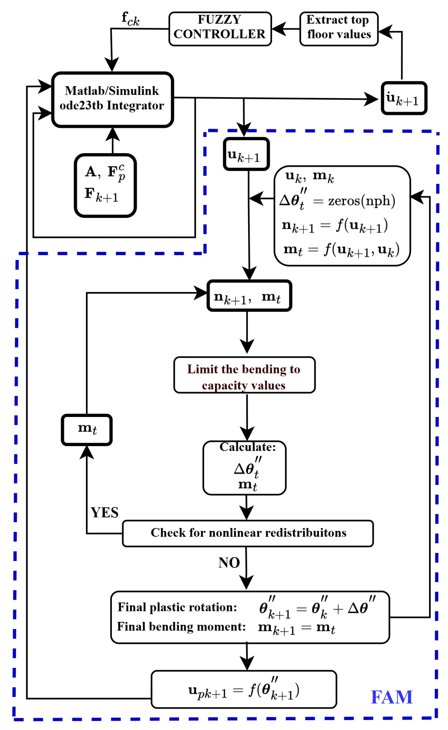
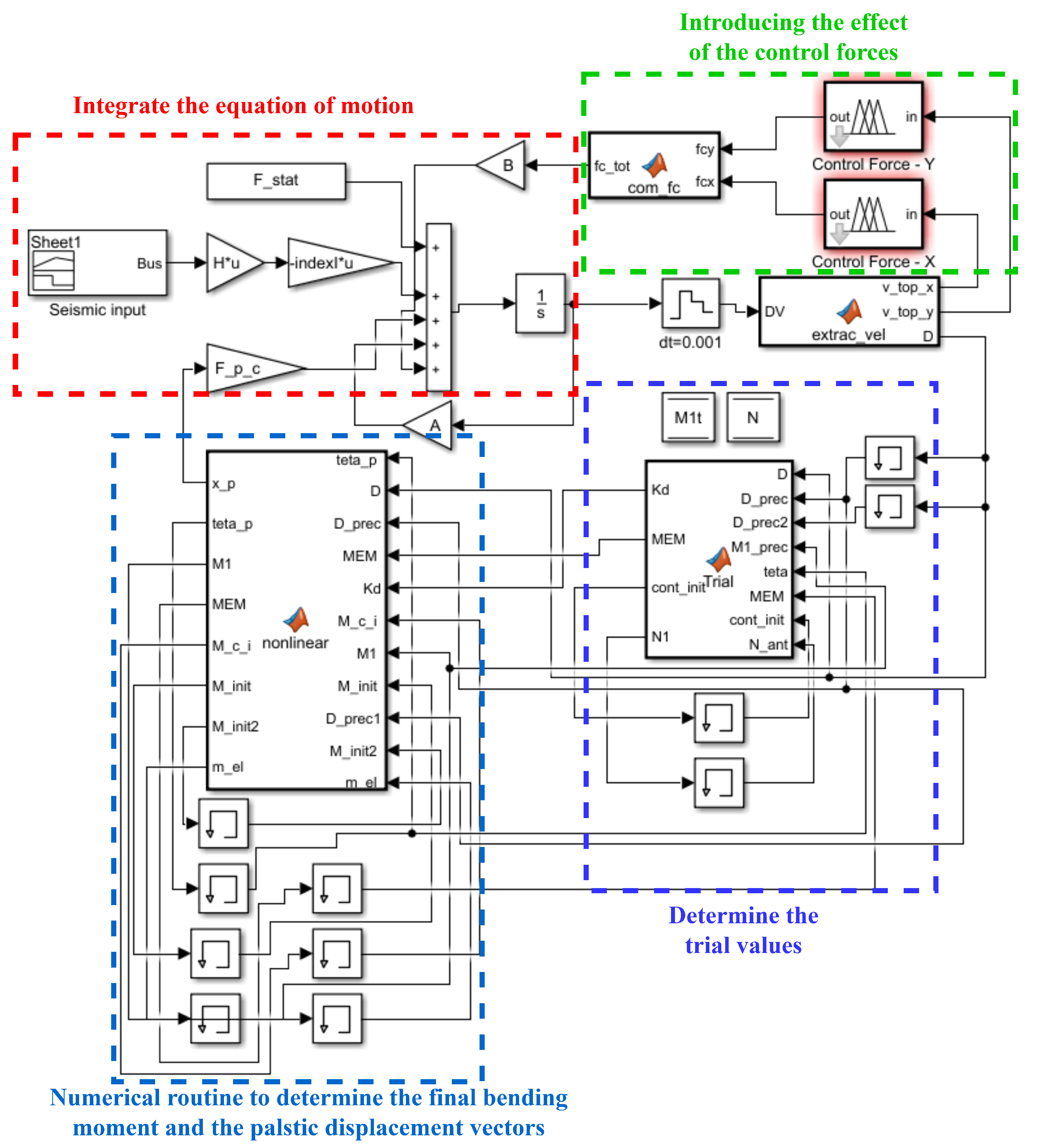
3.1. Simulation of the Nonlinear Dynamic Response

Recently introduced in structural analysis by refs. [34,35], the Force Analogy Method (FAM) is a highly efficient numerical approach that is capable of handling plasticity in a straightforward and concise manner. The key idea of FAM involves introducing a new vector of unknown values into the equation of motion that accounts for the inelastic displacements u p ( t ) (see Equation (1) where u ( t ) is the vector of structural displacements, M , K , C are the mass, stiffness, and damping matrices modeling the structural system, a g ( t ) is the vector of seismic inputs, and h is the vector that maps the seismic input on each degree of freedom).
M · u ¨ ( t ) + C · u ˙ ( t ) + K · u ( t ) = M · h · a g ( t ) + K · u p ( t )
where u k + 1 can be computed as described in Equation (2), based on the stiffness matrix, the plastic rotation vector, and the member force recovery matrix K which is obtained from the element stiffness matrix in local axis coordinates as presented in ref. [3].
u p ( t ) = K 1 · K · θ ( t )
The seismic simulation procedure, illustrated in Figure 2, comprises two main steps. Firstly, leveraging data from the preceding step, the explicit integration procedure defined in Equation (3) (developed by ref. [34]) is used to compute the displacement vector u k + 1 . Subsequently, trial values for the bending moment m t and inelastic rotation increment vector Δ θ t are determined. At the same time, the axial force vector n k + 1 is calculated based on the current step displacement vector u k + 1 .
Furthermore, the m t vector values are then individually compared to the bending capacities of the subsequent plastic hinges. In cases where bending exceeds the elastic limit, values are capped to capacity, and the exceeding effort is treated as an unknown plastic deformation increment.
Subsequently, the values in m t are recalculated and then undergo another comparison with capacity in order to assess any inelastic bending redistribution. If new values exceed the elastic limit, the m t is redirected to the capping routine; otherwise, final bending moments m t = m k + 1 and plastic rotations θ k + Δ θ t = θ k + 1 are computed.
Ultimately, the plastic displacement vector is calculated and introduced into the explicit integration formula to determine the next-step displacement vector.
As previously mentioned, the integration of the structural response is performed using the equivalent state-space form of the equation of motion in Equation (1) as presented in Equation (3) and consequently in discrete form in Equation (5).
z ˙ ( t ) = A · z ( t ) + F ( t ) + F p c · u p ( t ) + B f c ( t )
where:
z ˙ ( t ) = u ˙ ( t ) u ¨ ( t ) , z ( t ) = u ( t ) u ˙ ( t ) , A = O I M 1 K M 1 C , F ( t ) = 0 h · a g ( t ) = H · a g ( t ) , B = 0 M 1 D , F p c = O M 1 K ;
while the D matrix has the role of scaling the control forces on the desidegrees of freedom
z k + 1 = ode 23 tb ( A · z k + F k + 1 + F P c · u p k + B · f c k )
The results of the nonlinear dynamic simulation procedure were validated against those provided by a commercial structural analysis software as presented in the authors’ previous papers refs. [3,4].

3.2. The Active Control Algorithm

In order to simulate the active control system implementation, a fuzzy controller was employed. Fuzzy control systems were considered particularly relevant for this specific application due to their effectiveness in handling nonlinearities. A key advantage of using a fuzzy controller is its ability to compute control forces autonomously without requiring an explicit mathematical model of the structural dynamics. Instead of relying on predefined system matrices (mass, stiffness, and damping), the fuzzy controller determines control actions based on the structural response obtained at each time step from the numerical time integration scheme. This approach allows the controller to adapt to the evolving system behavior while remaining effective under varying conditions. This attribute underscores the robustness and versatility of the fuzzy control strategy, making it well-suited for simulating the active structural control of inelastic structures.
As previously highlighted, the efficacy of control strategies is evaluated in terms of their capacity to mitigate structural damage generated by inelastic deformations. Although reducing the hysteric energy involves minimizing structural displacements, the control algorithms used in this paper employ structural velocities as the input variable. This choice is based on the control theory principles, where the utilization of the derivative of the controlled quantity serves as a common input for controllers. By incorporating the derivative term into the control algorithm, we account for the reduction in the rate of displacement growth through proper control actions. At the same time, it is important to highlight that direct displacement measurement during seismic events might pose significant challenges due to the need for a fixed reference point. In contrast, measuring velocity proves highly feasible using a multitude of sensors.
It also can be argued that accelerometers are the most commonly used sensors for seismic structural response monitoring, and that several acceleration-based control strategies, such as direct acceleration feedback and acceleration-based optimal controllers, have been widely explored in structural control research. However, acceleration measurements alone tend to be highly sensitive to noise, particularly in real-world conditions. Although the structural response in this study is simulated, velocity inputs are considered in order to take into account real-world limitations of accelerometers in practical applications.
Regarding control output, the control forces are determined in each time step based on the values of top-story velocities and are applied independently on both the X and Y principal direction at center of mass of the top floor.
The numerical routine used to simulate the implementation of the control forces effect on the nonlinear dynamic structural response is illustrated in Figure 2. Using the previous step data ( z k , u p k and f c k ) and the seismic input vector F k + 1 , the current step velocity vector u ˙ k + 1 is determined. Furthermore, the top-story velocities on the principal direction are extracted and are fed into the fuzzy controllers in order to compute the subsequent control forces. In this process the inputs are transformed into linguistic variables through membership functions, which assign degrees of membership ranging from 0 to 1. These fuzzy values represent the degree to which each input belongs to each linguistic category defined. Next, the fuzzy controller applies the set of predefined rules to determine the appropriate control action. These rules are derived from engineering expertise. After applying the rules, the fuzzy controller aggregates the resulting linguistic outputs to generate a crisp control action. This process, known as defuzzification, transforms the linguistic outputs into a single numerical value, describing the control action to be implemented on each direction of the structural model. After the control force output is scaled on the desired degrees of freedom using the B matrix, the resulting vector is fed into the integrator in order to determine the structural response for the next step.
It must be emphasized that, in this study, the control forces are applied directly and instantaneously at the center of mass of the structural model, with their magnitude determined by the fuzzy control algorithm based solely on the simulated structural response. This approach assumes an idealized control system, free from the practical constraints typically encountered in real-world applications. Specifically, limitations such as actuator bandwidth, maximum stroke capacity, response delays, control latency, and potential power supply interruptions during strong seismic events are not explicitly modeled. While these constraints may influence the overall efficacy of a control system, the primary objective of this paper is to investigate the overall structural response under the assumption of idealized control forces. This approach allows for a clearer understanding of the fundamental behavior of the structure and control system interaction, without the added complexity of detailed actuator modeling. As such, the control application method employed here can be effectively assimilated to an idealized active mass damper system.
The overall nonlinear dynamic simulation procedure, developed within the Matlab/Simulink environment, is depicted in Figure 3. It consists of four primary subroutines which play the role of executing the main numerical operations. These encompass integrating the equation of motion, calculating trial bending moments and plastic rotation increments, determining bending moments and plastic displacement vectors, and accounting for the impact of control forces. The numerical operations within this subroutines have been described earlier in this section.

3.3. Damage Quantification

Quantifying structural damage is crucial for ensuring the safety and durability of buildings, particularly in seismically active regions. Nonlinear dynamic analysis serves as the foundation for most damage estimation techniques, providing detailed insights into structural behavior under seismic loads. Various estimation methods, including empirical approaches, analytical models, and advanced computational simulations, rely on these analyses to deliver comprehensive assessments.
In order to estimate the structural damage induced by earthquake excitation and encountered by the structural elements through plastic deformations, a damage index approach is used in this paper. Consequently, the aim of this study is to employ a widely recognized and robust damage index for evaluating the seismic performance of buildings. To achieve this, the Park–Ang damage index was selected, as it has been extensively used in the scientific literature for estimating structural damage in the context of seismic events, as evidenced by previous theoretical and experimental studies refs. [36,37,38,39].
The Park–Ang damage index was proposed by ref. [40] and was later updated by ref. [41]. Consequently, certain theoretical concepts employed in this paper are presented in this subsection. While the equations for the Park–Ang damage index are well-established and widely utilized in the literature, they are presented here for the sake of completeness and to ensure a smooth flow of the discussion. Therefore, the general expression used to determine the damage index of a structural model employing a plastic hinge approach is given in Equation (6).
D I = θ m θ r θ u θ r + β M y θ u E h
where θ m is the maximum of the rotation of the cross section during loading history, θ u is the cross-section ultimate rotation capacity, θ r is the recoverable rotation after unloading, β = 0 is a parameter accounting for strength degradation (no strength deterioration was considered, as buildings in seismic areas are endowed with high ductility), M y is the bending moment capacity of the cross section, and E h is the hysteresis energy dissipated by the structural element.
As introduced in the previous section, the hysteresis model used in this paper is based on the relationship between plastic rotation and bending moment. Consequently, the evolution of the damage index for a plastic hinge is described by Equation (7).
D I P H i ( t ) = θ m ( t ) θ u + β M y θ u E h P H i ( t )
where E h P H i ( t ) is the cumulative hysteresis energy dissipated up to time step t for the ith plastic hinge.
Additionally, in order to to quantify the structural damage at each story, the following expression can be used:
D I j ( t ) = i = 1 n λ i j ( t ) D I P H i ( t ) i = 1 : n , j = 1 : p
where n represents the number of plastic hinges in the j-th story, and p denotes the total number of stories. Additionally, λ i j ( t ) is the normalized dissipated hysteresis energy of the ith plastic hinge in the j-th story, relative to the dissipated hysteresis energy of the j-th story which is calculated using Equation (9).
λ i j ( t ) = E h P H i j ( t ) i = 1 n E h P H i j ( t e n d , k ) i = 1 : n , j = 1 : p
where E h P H i j ( t ) is the cumulative dissipated energy up to time step t for the i-th plastic hinge corresponding to j-th story, and i = 1 n E h P H i j ( t e n d , k ) is the maximum (or current) value attained during the loading history, representing the sum of all the cumulative dissipated hysteresis energy by the plastic hinges corresponding to the j-th story.
In a similar manner, using Equation (10), the damage index for the entire structure can be defined as follows:
D I s t r u c t u r e ( t ) = j = 1 p λ j ( t ) D I j ( t ) , j = 1 : p
where λ j ( t ) is the normalized cumulative energy dissipated by the j-th story relative to the total cumulative dissipated energy of the entire structure, as given by Equation (11).
λ j ( t ) = E h j ( t ) j = 1 p E h j ( t e n d ) , j = 1 : p

4. Case Study

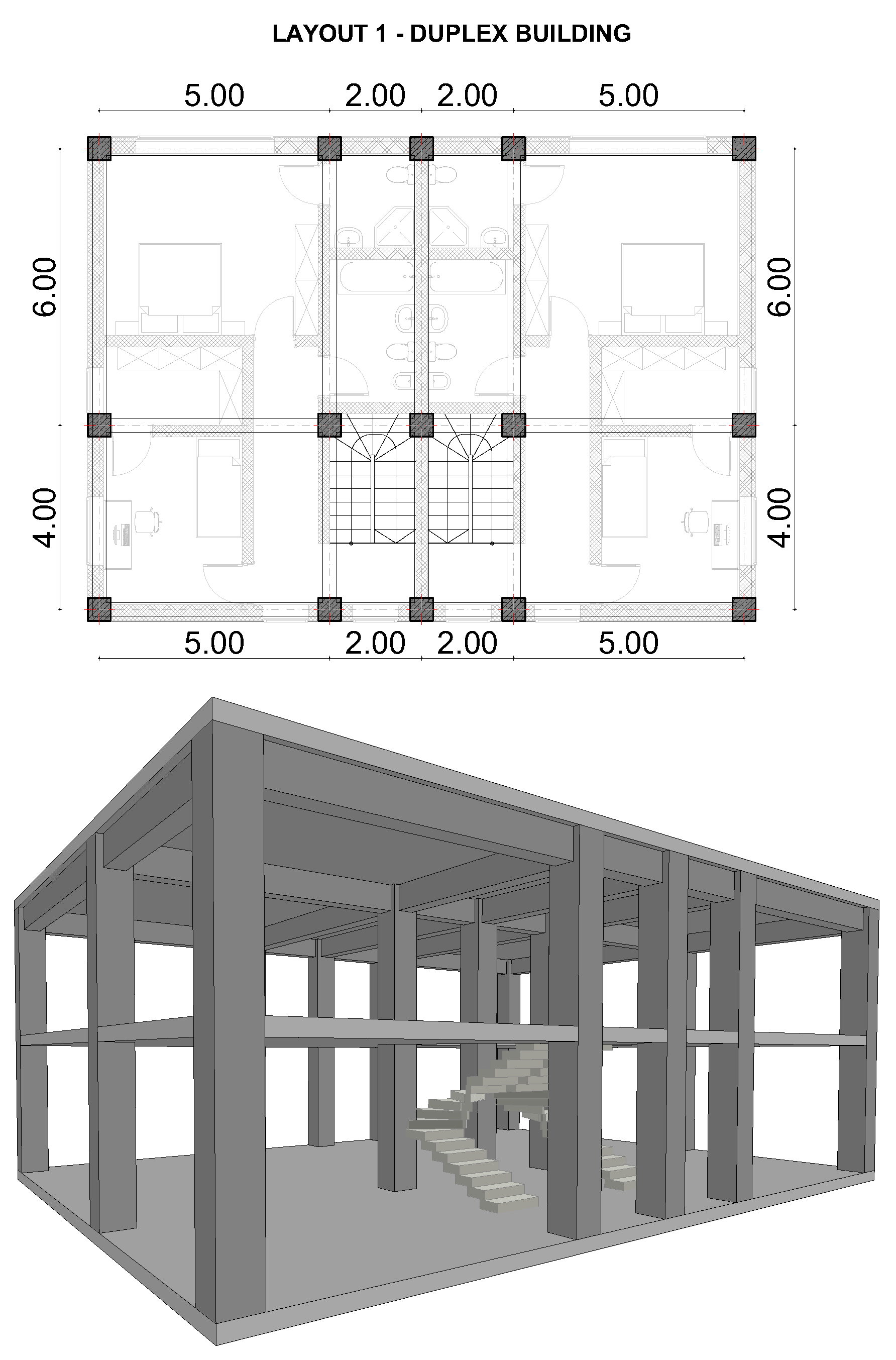
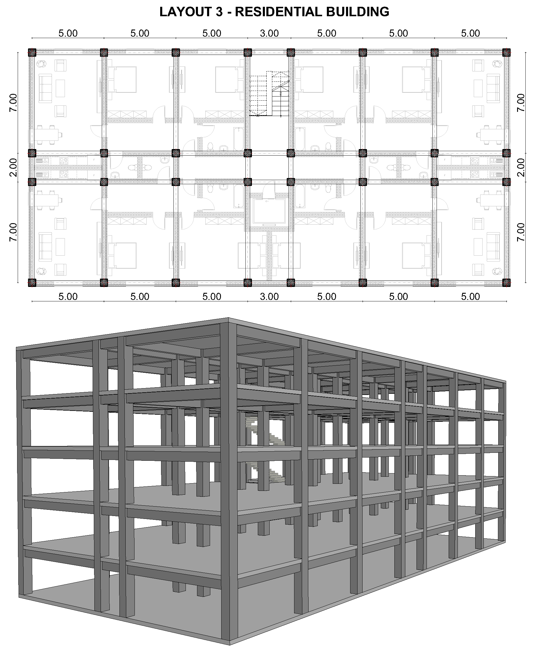
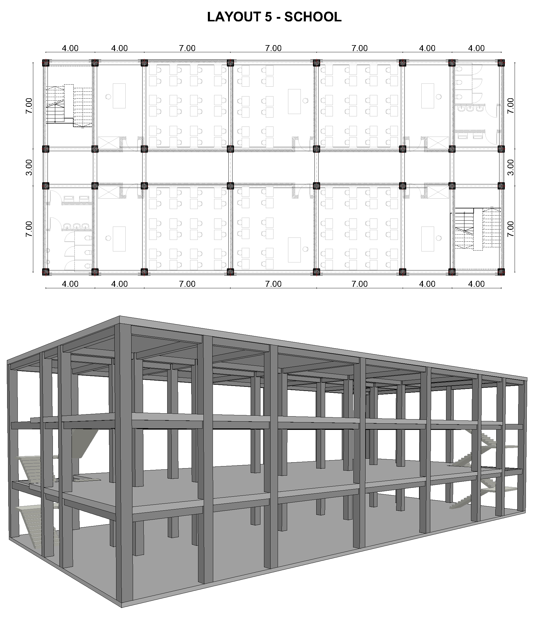
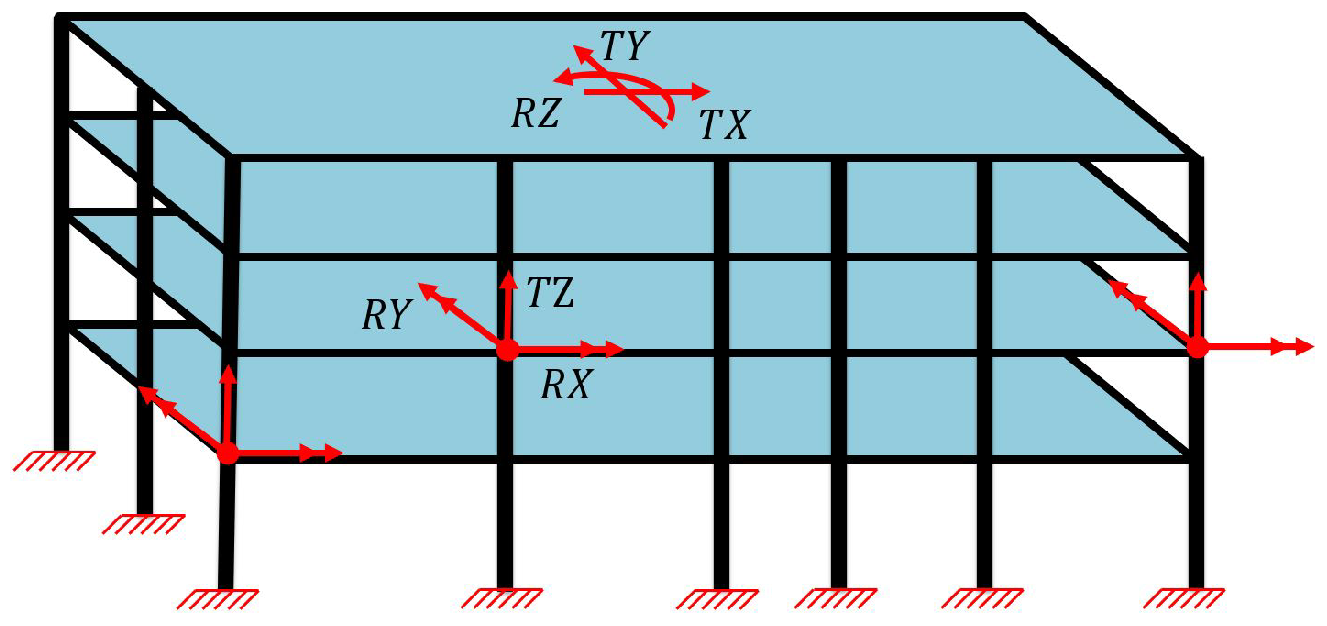
4.1. Description of Structural Models
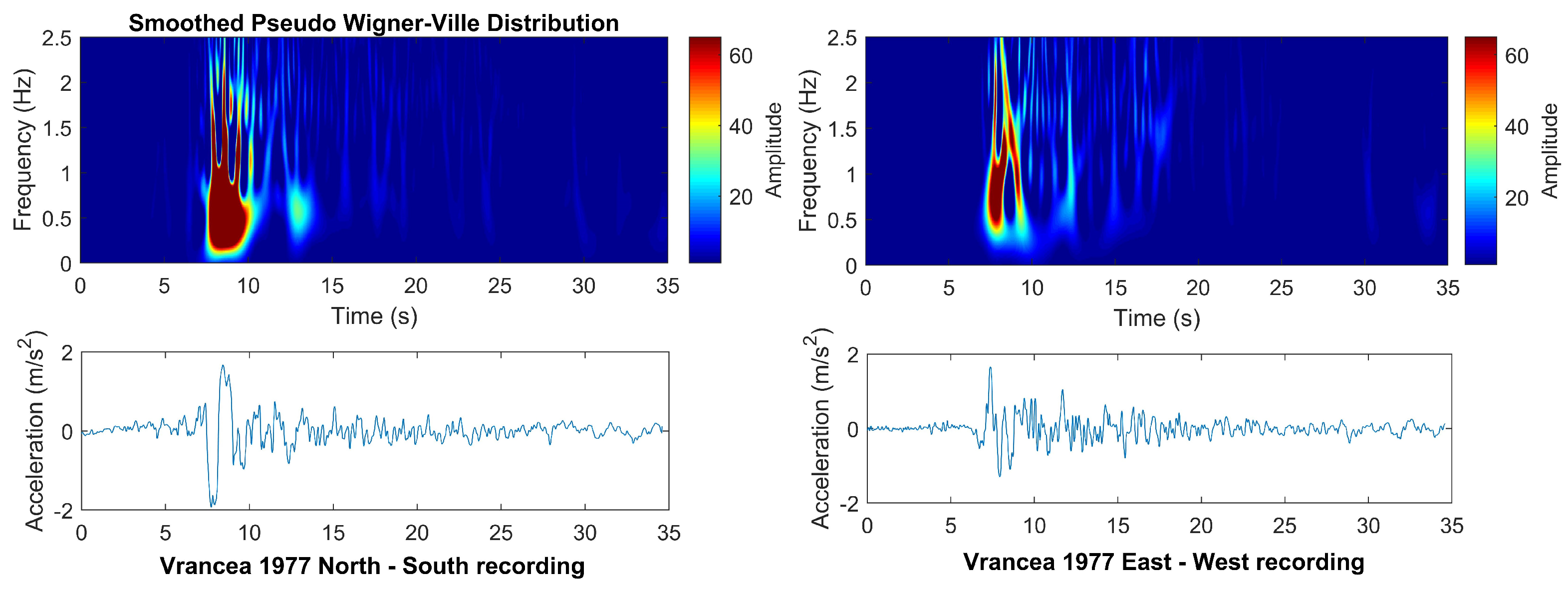
To investigate the efficacy of active control implementation, a series of nonlinear dynamic simulations was conducted. The objective was to establish the relationship between the damage index and the maximum control forces applied on the two principal directions. Therefore, five types of reinforced concrete buildings with distinct architectural layouts were analyzed, each representing a common functional category: three types of residential buildings (Layouts 1–3), an office building (Layout 4), and a school (Layout 5). For each of these structural models, the evaluation of damage indices was undertaken through a series of nonlinear dynamic simulations. In each simulation, the magnitude range of the applied control forces was varied systematically, aiming to ascertain the extent to which increasing control actions mitigates structural damage. Furthermore, the number of stories for each layout was selected to align with the typical characteristics of each functional category. Specifically, Layout 1 features a two-story building, Layout 2 comprises buildings with four and five stories; Layout 3 consists of buildings with four and five stories; Layout 4 includes buildings with five and nine stories; and Layout 5 includes three-story buildings.
While it is common to encounter higher numbers of stories in large office and residential buildings, as represented by Layouts 3 and 4, several factors constrain this possibility. Moment-resisting frame structures, which are typical for these layouts, are often limited in height due to deformation and angular drift restrictions specified by seismic codes. Moreover, in taller buildings, higher modes of vibration become significant in the seismic response, necessitating more complex sensing and control systems to effectively counter these motions. While these complexities are worth investigating, they exceed the scope of this study, which focuses on the effectiveness of control systems in more conventional scenarios.
Moreover, considering that the study focuses on buildings situated in seismic areas, only regular buildings with rectangular layouts were selected. This selection aligns with the design philosophy and building codes in seismic regions which prioritize simplicity and regularity in structural configurations. Such designs are favorable because they offer more predictable seismic responses, reducing the potential for irregularities that could lead to unexpected structural behavior during an earthquake. Consequently, the study ensures that the analyzed buildings and the detailing of the structural elements are representative of standard construction practices and compliant with safety regulations in seismic zones.
Each structural model is developed using beam-type finite elements, with six degrees of freedom (DOFs) per joint. The mass and stiffness matrices describing these elements are assembled through a topological matrix, resulting in global mass M and stiffness K matrices that accurately represent the building’s structural system. Furthermore, assuming a proportional Rayleigh-type damping model, coefficients α r and β r , corresponding to a 5 % damping ratio on the first two eigenmodes, were used to determine the damping matrix employing the formula in (12). More detail about the matrix describing the structural elements used in this paper are presented in detail in the authors’ previous paper [3].
C = α r · M + β r · K
For all models, the material properties and static loads applied are consistent, as detailed in Table 1. In addition to these uniform properties, several input parameters were customized for each building model, depending on its specific layout. These variable parameters include the number of stories, story heights, the dimensions of structural elements, and the bending and axial capacities of beams and columns. Along with these, the main parameters defining the numerical models, including dynamic properties such as the fundamental natural periods of the buildings, as well as the number of plastic hinges, are outlined in Table 2, Table 3 and Table 4.
Given that most reinforced concrete buildings possess thick, rigid slabs, the full model with six degrees of freedom per node can be simplified by applying a rigid diaphragm constraint. This simplification results in a model where each node exhibits three degrees of freedom (two rotations RX, RY about the principal horizontal axes and one vertical translation TZ), while an additional three degrees of freedom are defined at the center of mass of each floor level (two horizontal translations TX, TY and one rotation about the vertical axis RZ). The implementation of a diaphragm constraint offers an effective compromise between computational efficiency and the accuracy of the models (Figure 4).
Furthermore, the seismic inelastic behavior is modeled using the concentrated plasticity approach, as described in the previous section. Considering the fact that beams are usually embedded in slabs, and therefore bending moment is the only significant member force that generates inelastic behavior, for beams a bending moment plastic hinge was employed. Therefore, for this type of element the bending capacities are set to a constant value m c g r (kNm) throughout the entire analysis. In the case of columns, the behavior is more complex. Significant bending moments can develop along the principal directions of the cross section, and the bending capacities are influenced by the interaction with axial forces. Consequently, for columns in a 3D frame structure, plastic hinges were defined by considering the interaction between axial force P and bending moments m y , m z (commonly referred to as P m m interaction). The column yielding surface f ( m y , m z , P ) (Figure 5) was defined as previously proposed by G. Powell et al. [42]. The yielding surface defines the interaction between axial force and biaxial bending moments along the principal directions, effectively characterizing the bending capacity of the column for each level of axial load. As the axial force varies, the corresponding bending moment capacities are modified due to the interaction effects inherent in column behavior. When the trial internal forces lie outside the admissible domain defined by the yield surface, a return mapping algorithm is employed to project the trial point back onto the surface. This projection ensures compliance with plasticity theory and enforces the yield condition. The amount by which the trial state exceeds the yield surface is interpreted as inelastic deformation, and the corresponding plastic rotation increment is consistently computed.
f ( m y , m z , P ) = m y m y p 2 + m z m z p 2 + P P b P p 2 1
where m y p = m z p represent the maximum bending moments, P p define the vertical semi-axis of the ellipsoid, P b represents the axial force at maximum moment, and ( m y , m z , P ) are the member forces varying along y, z, and x axis, respectively. Furthermore, P b + P p is the cross-section compression capacity while P b P p is the cross-section tension capacity.
Regarding the hysteresis models, a peak-oriented model is employed to define the relationship between bending moment and plastic rotation for each beam plastic hinge. In contrast, the hysteretic behavior of column 3D plastic hinges is determined by the sliding paths imposed by the interaction capacity surface. Further details on the hysteresis models used are available in a previous work of the authors [4].
It is important to note that the shear behavior of structural elements is assumed to be elastic. This assumption can be accepted, given the fact that the structural models examined in the paper are considered newly designed and comply with the provisions outlined in Eurocode 8 (Sections 5.4.2.2 and 5.4.2.3). The seismic design of these structures follows the capacity design principles, where the design seismic shear force is calculated as the maximum bending moments associated with the plastic rotation mechanism of the elements divided by the shear span length. This approach ensures that, under seismic loading, even when plastic rotations occur and the maximum bending capacity is reached, the corresponding shear forces do not exceed the design shear strength of the elements, which means elastic behavior is exhibited. At the same time, the code requires the use of transverse reinforcement (stirrups) within critical regions to confine concrete and enhance its shear strength. This reinforcement strategy is designed to prevent brittle shear failures and ensure that any inelastic behavior is primarily due to bending moments. Additionally, Eurocode 8 provides detailing rules for beam–column joints, including confinement reinforcement and anchorage requirements, to avoid damage under seismic loading. As a result, the research does not consider failure or non-ductile damage due to shear stress, with plastic rotation being the only source of nonlinearity. Moreover, the potential deterioration of beam-to-column connections is also not explicitly modeled during the simulations.

4.2. Seismic Inputs

Regarding the seismic input, two historical earthquake records, Vrancea 1977 and El Centro 1940 were selected to assess the effectiveness of active control in mitigating structural damage. These records were deliberately chosen due to their distinct dynamic characteristics, making them representative for a broad range of seismic scenarios encountered in practice. The Vrancea 1977 earthquake is a deep-focus subcrustal event associated with a reverse fault mechanism and characterized by long-period spectral content and extended shaking duration. Such ground motions predominantly affect tall, flexible structures, amplifying their dynamic response. In contrast, the El Centro 1940 earthquake, generated by shallow strike-slip faulting along the Imperial Fault, features short-duration, high-frequency ground motion, which generate high amplifications on low- and mid-rise buildings. In addition to their spectral complementarity, both records exhibit significant peak ground accelerations which are associated with very destructive seismic events.
The Vrancea earthquake was one of the most significant seismic events in eastern Europe and struck Romania on 4 March 1977. It registered a magnitude of 7.4 on the Richter scale and had an estimated focal depth of about 94 km. As presented in Figure 6 the main seismic frequencies recorded on the North–South and East–West directions were in the range of 0.1 to 2 Hz. These lower frequencies are particularly hazardous to tall, flexible structures, typically those that are seven stories or taller. The PGA recorded was approximately 0.2 g in the North–South direction, while 0.16 g in the East–West direction. More insights on Vrancea seismic motions can be found in [43].
The El Centro earthquake that occurred on 18 May 1940 in the Imperial Valley of California was another landmark event in seismic history. This earthquake had a magnitude of 6.9 and a focal depth of approximately 10 km. The seismic motion recorded on North–South and East–West directions revealed predominant frequencies in the range of 0.5 to 5 Hz, as presented in Figure 7. These frequencies can severely impact low and mid-rise buildings, typically those between two and seven stories. The PGA recorded was approximately 0.33 g in the North–South direction and 0.22 g in the East–West direction.

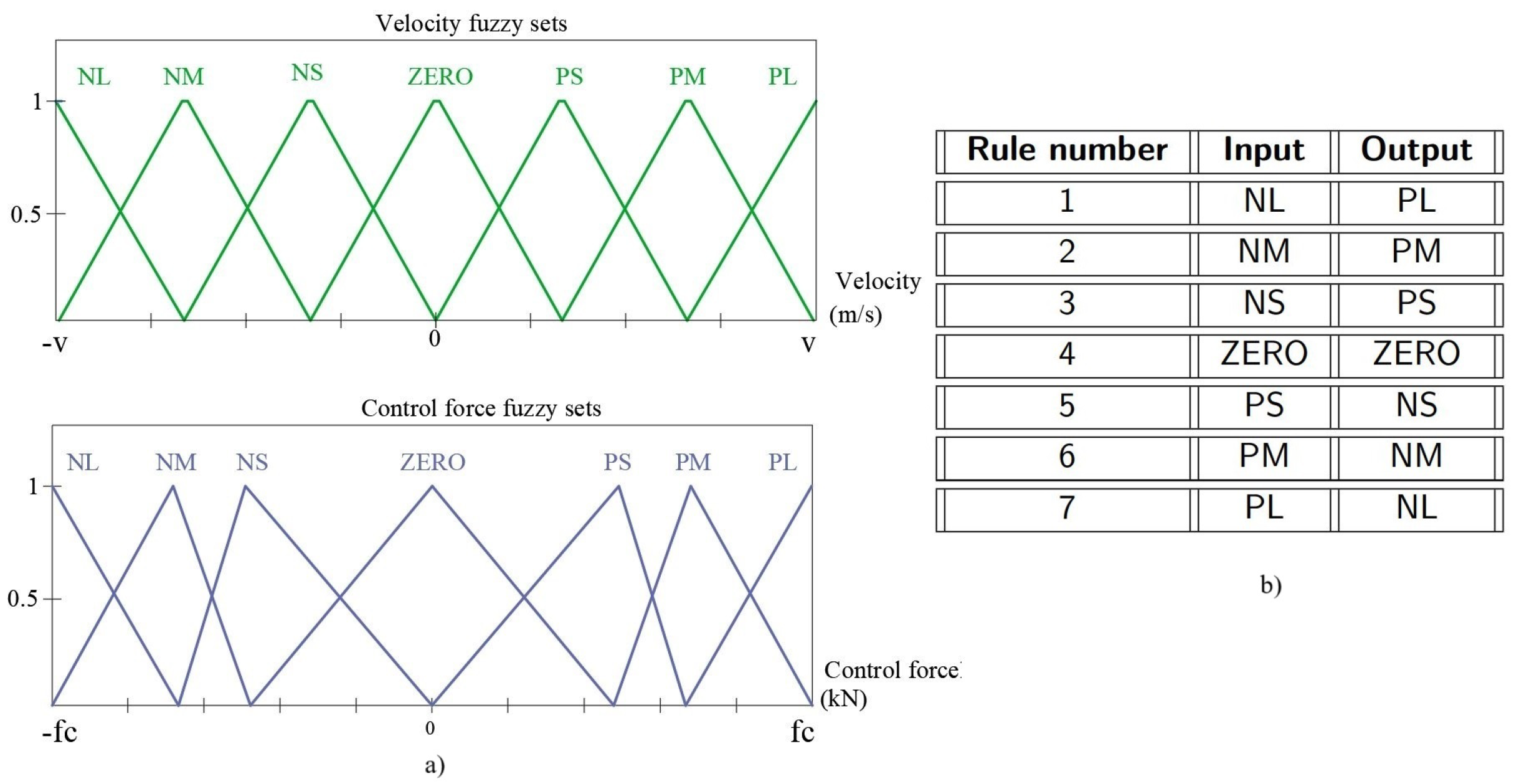
4.3. Fuzzy Control Algorithm

As previously mentioned, the effect of active control system on the structural response is simulated using two fuzzy control algorithms that apply control actions in both principal horizontal directions of the building. To describe each controller input and output, two fuzzy sets are employed (Figure 8a). Consequently, the inputs of controllers are the velocities at the top floor, while the outputs are the control forces applied in each principal direction. Moreover, the fuzzy sets have 7 triangular membership function (Negative Large (NL), Negative Medium (NM), Negative Small (NS), Zero, Positive Small (PS), Positive Medium (PM), Positive Large (PL)) and are linked through 7 rules (Figure 8b). The fuzzy rule design is based on the principle of generating a control force that acts in the opposite direction of the system’s velocity, aiming to mitigate the increasing rate of displacement variation. The fuzzy rules follow an inverse relationship between the velocity input and the control force output. When the velocity is large in one direction, a strong force is applied in the opposite direction to decelerate the system. Conversely, smaller velocities result in weaker opposing forces, ensuring smoother control. The rules are designed symmetrically around zero velocity. If the velocity is Negative Large, the system applies a Positive Large control force to counteract the response. As the velocity decreases to Negative Medium or Negative Small, the control force is reduced to Positive Medium and Positive Small, respectively. When the velocity is Zero, no control action is applied, reflecting the system balanced state. Similarly, for positive velocities, the system applies opposing control forces. A Positive Small velocity triggers a Negative Small force, while Positive Medium and Positive Large velocities are countered by Negative Medium and Negative Large forces. This design ensures that larger velocities receive stronger opposing forces, while smaller velocities receive softer corrections. The symmetric structure of the rules combined with the triangular fuzzy sets creates a proportional-derivative (PD)-like behavior, where the magnitude of the control force depends on the velocity input.
During each simulation, the universes of discourse describing input and output are adjusted in order to amplify the magnitude of control forces and achieve a proportional response from the control algorithm in correlation with the structural response. This process reveals the relation between the maximum control forces and the resulted damage index. The input boundary values for each simulation were individually determined based on the peak velocity observed at the top floor. In contrast, a consistent set of output boundary values was established for each building across all simulations. These output boundaries were set at ± 600 , ± 1200 , ± 2400 , ± 3600 , and ± 4800 kN to systematically evaluate the extent to which increasing control forces reduces the damage index. Defuzzification was performed using the center of gravity method.
It must be mentioned that the reliability of the fuzzy controller is supported by previous studies published by the authors [44,45], in which the performance of fuzzy and LQR controllers was investigated under similar conditions. These studies showed that the fuzzy controller can effectively reduce structural response and achieve performance comparable to that of the LQR controller.

4.4. Results

In this section, results are presented using bar charts that depict the maximum control forces required to achieve specific levels of structural damage. Each chart illustrates the maximum control forces applied alongside the resulting damage indices extracted from each individual simulation. This visualization allows for a clear comparison of how varying control force magnitudes influence structural damage, thereby quantifying the ‘cost’ in terms of active control forces necessary for damage mitigation. To obtain this data for each structural model, we conducted a series of simulations, adjusting the intervals defining the universe of discourse for the fuzzy controller during each analysis, as detailed in the case study section. This adjustment lead to increasingly higher control forces and, consequently, lower damage indices. This methodology enabled us to observe and analyze the relationship between control force variations and structural damage mitigation level, in order to provide a comprehensive understanding of the control requirements needed to achieve certain structural performances.
A total of 66 simulations were conducted incorporating five structural layout types, with varying configurations, subjected to seismic inputs from the 1977 Vrancea and 1940 El Centro earthquakes. This number resulted from the total analyses conducted for each combination of structural layout and number of stories. It is important to note that in each case, multiple simulations were required establish the relationship between the control force magnitude and the corresponding damage index. The simulations were performed progressively, starting from a scenario with zero control force, which led to the maximum damage index, up to the case where the applied control force was maximized, resulting in zero or minimal structural damage.
The primary objective was to investigate the relationship between the maximum control forces required in both the X and Y principal directions and the resulting damage index (DI). The simulations covered a range of structural configurations, from simpler, low-rise buildings to more complex, multi-story structures, representing the typical building types found in urban areas. The layouts and the subsequent 3D representation of the structural systems are pictured in the Appendix A.
It is important to note that although the damage index values for scenarios without control forces are substantial, they reflect current design practices, where strength factors used for frame structures can reduce design loads by up to 5 times, relying on additional energy dissipation through inelastic deformations and damping. Moreover, the results should be interpreted considering that, according to the scientific literature, actual active control forces implemented in practice, typically reach a maximum of 500 kN as documented by ref. [32] (KK100 building from Shenzhen, Guangdong, China) paper. At the same time, to understand the phisical significance of the damage indices, Table 5 offers a detailed interpretation of these values according to [46,47].
Figure 9 and Figure 10 present heatmaps illustrating the dependence between the applied maximum control force and the corresponding damage index for both earthquake scenarios.
In case of Vrancea earthquake, which features long-period dominant content, active control proved to be effective for low- to mid-rise buildings. For Layout 1, a two-story duplex residential building with a total floor area of 140 m2, the damage index decreased from 0.15 to 0 with the application of moderate control forces. In Layout 2, comprising four- and five-story residential buildings, a substantial damage reduction was also observed. For the 4-story case, a maximum control force of 1621 kN was required to achieve the no damage state, whereas the 5-story configuration required forces up to 2015 kN to reach a minimum damage index value of 0.08.
The response of Layout 3, a larger residential building, revealed a reduction in the damage index from 0.25 to 0.07 for the 4-story structure using a maximum control force of 1080 kN. In contrast, the 5-story building demonstrated significantly higher control force demands (3242 kN), underscoring the sensitivity of structural response to even slight variations in fundamental period.
Layout 4, representing a typical office building, displayed higher vulnerability. For the 5-story structure, even if significant control forces were applied, the damage index could not be reduced below the repair threshold, indicating that structural damage remained beyond acceptable limits. At the same time, the 9-story building, characterized by a fundamental period of 1.1 s, fell within the amplification range of the Vrancea input, resulting in a damage index of up to 0.61 in the uncontrolled scenario. Notably, the marginal benefit of additional control force diminished as the base shear increased, highlighting a nonlinear trade-off between control effort.
The best performance under Vrancea input was recorded in Layout 5, a 3-story school building. The initial damage index of 0.15 (minor damage) was effectively reduced to zero through the application of a relatively modest 540 kN control force, indicating high control efficiency in this configuration.
In contrast, the El Centro earthquake, which exhibits higher frequency components, induced significantly greater structural demands. In Layout 1, the damage index in the uncontrolled case reached 0.35, more than double the Vrancea result for the same structure, reflecting the amplified response of short-period systems. Active control implementation reduced the DI value to 0.05, but required considerably more force input.
For Layout 2, the demand for control effort was substantially increased. The 5-story residential building required up to 2663 kN to achieve a no-damage state, while for the 4-story case a maximum of 2161 KN was necessary. A similar trend was observed in Layout 3, where force demands escalated significantly under El Centro excitation for both the 4- and 5-story cases.
Furthermore, while Layout 4 5-story configuration remained in a heavily damaged state (DI = 0.19) even with high control forces applied, the 9-story office structure showed improved behavior under El Centro. Its longer fundamental period placed it outside the seismic record amplification band, limiting the uncontrolled damage index to 0.24. Nevertheless, the efficiency of control forces reduced as building height and inertial mass increased, a trend consistent with the Vrancea results.
Lastly, Layout 5 experienced a substantial increase in structural response under El Centro, with a damage index value of 0.37 in the case without control. Reducing the DI to zero necessitated forces between 2021 kN and 3241 kN, highlighting the significant effort required to protect mid-rise structures against high-frequency ground motions.
For an integrated perspective, Figure 11 and Figure 12 illustrate the relations between maximum control forces and damage index for the different structural layouts under both earthquake input scenarios. These curves can serve as a guide for active control system designers to estimate the magnitude of the required control forces for a specific building type in the context of earthquake scenarios similar to El Centro and Vrancea 1977. These figures show that in cases where the required control forces are relatively low to moderate (e.g., Layouts 1 and 2 in the Vrancea case), the implementation of active control systems with current technological advancements, in terms of control force magnitudes, can provide notable structural damage reduction. However, in cases requiring very high control forces (e.g., Layouts 3, 4, and 5 in the El Centro case), the implementation of such systems remains an area for further exploration, as technology continues to evolve and more powerful and efficient control systems are developed for seismic applications.

5. Research Significance

One of the original contributions of this paper is the use of 3D nonlinear dynamic simulations to assess the performance of active control systems. In contrast to prior studies that rely mostly on simplified 2D elastic models, this research incorporates detailed 3D modeling of inelastic structural behavior, enabling a more accurate evaluation of structural response under strong seismic excitations.
A further original contribution lies in the development of control force–damage index curves for various building configurations and seismic scenarios. These curves offer valuable insights for practitioners, allowing them to estimate the required control effort to achieve specific damage reduction targets.
Moreover, given that current applications and research on active structural control primarily focus on mitigating structural response to wind or moderate earthquakes, this study makes a key contribution by evaluating the effectiveness of active control in reducing structural damage during strong earthquakes with long return periods.
Another significant contribution of this study is the development and open-access release of a custom simulation platform for nonlinear dynamic analysis of actively controlled structures. This tool not only ensures full transparency and enables replication of the presented results, but also serves as a flexible foundation for future research. Researchers can enhance the underlying nonlinear modeling techniques, explore alternative or more advanced structural control algorithms, or test the effectiveness of active control systems across a wider range of building typologies and seismic excitations.

6. Conclusions

In this paper, a series of nonlinear dynamic simulations were conducted to evaluate the effectiveness of active structural control in mitigating seismic-induced structural damage. The analysis examined five building types with distinct architectural layouts—three residential buildings (Layouts 1–3), an office building (Layout 4), and a school (Layout 5). Each was subjected to seismic inputs from two earthquakes with distinct frequency characteristics: the Vrancea 1977 event, known for its dominant low-frequency content, and the El Centro 1940 event, which contains stronger high-frequency components. Moreover, the study aims to investigate the relationship between maximum control force demands and the corresponding damage indices across various building types and different seismic scenarios.
The paper aims to fill a gap in the scientific literature by addressing the limitations of existing studies, which primarily rely on simplified numerical models with a limited number of degrees of freedom and focus on elastic analysis and in-plane structural responses to evaluate the effectiveness of active control. While these studies assess performance using response-based metrics such as peak displacements, floor accelerations, and story drifts, they fail to establish a direct connection between active control effectiveness and the reduction of seismic-induced structural damage. In contrast, our study employs 3D nonlinear dynamic simulations to provide a more realistic and reliable evaluation of active control, offering more robust results. Furthermore, as the literature lacks studies that assess the efficiency of active control in reducing seismic structural damage, our work introduces a novel perspective, emphasizing the relationship between control force requirements and the resulting damage index, thereby making a notable contribution in the field.
Moreover, given that current applications and research on active structural control primarily focus on mitigating structural response to wind or moderate earthquakes, this study makes a key contribution by evaluating the effectiveness of active control in reducing structural damage during strong earthquakes with long return periods.
To support ongoing research in active control of inelastic structures, the custom developed software platform used in this paper is made accessible to interested researchers under an open-access license. It can be downloaded from the following website: https://doi.org/10.5281/zenodo.13787522, (accessed on 16 March 2025).
Key findings indicate that active control implementation can effectively reduce structural damage in inelastic structures, as demonstrated by the control force–damage index relationships derived in the previous section. These results show that the effectiveness of these systems is highly dependent on the characteristics of the seismic input and the specific structural configuration.It must be noted that these conclusions are based on simulations conducted on only eight structural models subjected to only two distinct seismic inputs and should be further validated through a large-scale analysis incorporating a wider range of structural models and seismic excitations.
The development of the control force–damage index curves, describing the relationship between maximum control forces required and damage indices for various structural layouts, represents a significant and distinctive result of this paper. These curves, derived for typical building configurations, provide valuable insights for active control system designers, enabling them to estimate the control forces required to achieve a targeted damage state in different building types under earthquake scenarios similar to El Centro 1940 and Vrancea 1977.
Regarding the limitations of this study, it must be noted that, based on standard practices in the field, the shear behavior of the structural elements was modeled as elastic, while the beam-to-column connections were assumed to be rigid. At the same time it is also important to acknowledge that the study adopts an idealized representation of the control forces, which are applied directly and instantaneously at the structural model’s center of mass, as determined by the fuzzy control algorithm. Practical challenges typically associated with real-world implementation such as actuator stroke limitations, delays in force computation and application, potential power supply failures during extreme seismic events, and reliance on real-time feedback are not explicitly considered in the analysis. While these factors may affect the overall performance of a control system, their inclusion is beyond the scope of this work. The primary objective of this study is to provide insight into the fundamental structural response under the assumption of idealized control forces, serving as a baseline for future research addressing implementation-related complexities. At the same time it should be noted that the control force magnitudes obtained in this study exceed those typically used in current practice. Nonetheless, recent advancements, such as high-capacity actuators developed by SISMALAB, indicate the potential for future implementation of such systems.
For a more comprehensive understanding of this subject, future research should incorporate a broader range of numerical models to better capture diverse structural behaviors. Additionally, analyzing a wider spectrum of seismic motions is essential for improving the reliability of findings. Advancements in control algorithms should also be pursued to enhance performance and responsiveness, while machine learning techniques could be used to predict control force demands and structural damage more effectively. Moreover, experimental testing should be prioritized to validate the real-world performance of active control systems under actual seismic conditions.

Author Contributions

Conceptualization, R.I.M. and V.C.; methodology, R.I.M.; software, V.C.; validation, R.I.M., K.-C.L. and C.P.; formal analysis, V.C.; investigation, R.I.M.; resources, K.-C.L.; data curation, R.I.M.; writing—original draft preparation, R.I.M. and V.C.; writing—review and editing, C.P. and K.-C.L.; visualization, C.P.; supervision, V.C.; project administration, V.C.; funding acquisition, V.C. All authors have read and agreed to the published version of the manuscript.

Funding

We want to express our gratitude to the “Academy of Romanian Scientists, Ilfov 3, 050044 Bucharest, Romania” for funding this research work. We would also like express our gratitude to the National University of Science and Technology POLITEHNICA Bucharest (UNSTPB), Bucharest, Romania for funding this work.

Data Availability Statement

The raw data supporting the conclusions of this article will be made available by the authors on request.

Conflicts of Interest

The authors declare no conflicts of interest.

Abbreviations

List of Symbols and Abbreviations
SymbolDescription
D I Global structural damage index
D I P H i Damage index of plastic hinge i
D I j Damage index for story j
D I s t r u c t u r e Damage index for the entire structure
θ m , θ r , θ u Max, recoverable, and ultimate plastic rotation
M y Yield bending moment capacity
E h , E h P H i , E h j Dissipated hysteresis energy (total, hinge-level, or story-level)
λ i j , λ j Weighting factors based on relative dissipated energy
T 1 , T 2 , T 3 First, second, and third natural periods
u ( t ) , u ˙ ( t ) , u ¨ ( t ) Displacement, velocity, acceleration vectors describing structural response
M , K , C Mass, stiffness, damping matrices describing the structural model
a g ( t ) Ground acceleration input vector
u p ( t ) Plastic displacement vector
θ ( t ) Plastic rotation vector at plastic hinge locations
z ( t ) State vector for state-space model
A , B , F , F p c State-space matrices
P, m y , m z Axial force and bending moments on y and z axes of the cross section
P p , P b Peak axial capacity and axial force at balance point
m y p , m z p Bending moment capacities on y and z directions of the cross section
n p h Total number of plastic hinges
AMDActive Mass Damper
PGAPeak Ground Acceleration
FAMForce Analogy Method
SPWVDSmoothed Pseudo Wigner–Ville Distribution

Appendix A

Figure A1. Layout 1 with 3D representation.
Buildings 15 01402 g0a1
Figure A2. Layout 2 with 3D representation.
Buildings 15 01402 g0a2
Figure A3. Layout 3 with 3D representation.
Buildings 15 01402 g0a3
Figure A4. Layout 4 with 3D representation.
Buildings 15 01402 g0a4
Figure A5. Layout 5 with 3D representation.
Buildings 15 01402 g0a5

References

  1. Mobaraki, B.; Vaghefi, M. The Effect of Protective Barriers on the Dynamic Response of Underground Structures. Buildings 2024, 14, 3764. [Google Scholar] [CrossRef]
  2. Koutsoloukas, L.; Nikitas, N.; Aristidou, P. Passive, semi-active, active and hybrid mass dampers: A literature review with associated applications on building-like structures. Dev. Built Environ. 2022, 12, 100094. [Google Scholar] [CrossRef]
  3. Nica, G.B.; Munteanu Ruben, I.; Calofir, V.; Iancovici, M. Modelling nonlinear behavior of 3D frames using the Force Analogy Method. Structures 2022, 35, 1162–1174. [Google Scholar] [CrossRef]
  4. Munteanu, R.I.; Moţa, F.; Calofir, V.; Baciu, C. New Approach to Nonlinear Dynamic Analysis of Reinforced Concrete 3D Frames; An Accurate and Computational Efficient Mathematical Model. Appl. Sci. 2022, 12, 1692. [Google Scholar] [CrossRef]
  5. Munteanu, R.I.; Ruxandra, E.; Cătălin, B.; Vasile, C. A new perspective into torsional inelastic response of actively controlled irregular multistorey buildings. Alex. Eng. J. 2023, 71, 691–706. [Google Scholar] [CrossRef]
  6. Soong, T.T.; Spencer, B.F. Active Structural Control: Theory and Practice. J. Eng. Mech. 1992, 118, 1282–1285. [Google Scholar] [CrossRef]
  7. Spencer, B.; Nathan, M.; Newmark; Newmark;Nagarajaiah, S. State of the Art of Structural Control. J. Struct. Eng.-ASCE 2003, 129, 845–856. [Google Scholar] [CrossRef]
  8. Saaed, T.E.; Nikolakopoulos, G.; Jonasson, J.E.; Hedlund, H. A state of the art review of structural control systems. J. Vib. Control 2015, 21, 919–937. [Google Scholar] [CrossRef]
  9. Venanzi, I. A Review on Adaptive Methods for Structural Control. Open Civ. Eng. J. 2016, 10, 653–667. [Google Scholar] [CrossRef]
  10. Dyke, S.J.; Spencer, B.F., Jr.; Quast, P.; Kaspari, D.C., Jr.; Sain, M.K. Implementation of an Active Mass Driver Using Acceleration Feedback Control. Comput.-Aided Civ. Infrastruct. Eng. 1996, 11, 305–323. [Google Scholar] [CrossRef]
  11. Nagashima, I.; Shinozaki, Y. Variable gain feedback control technique of active mass damper and its application to hybrid structural control. Earthq. Eng. Struct. Dyn. 1997, 26, 815–838. [Google Scholar] [CrossRef]
  12. López-Almansa, F.; Andrade, R.; Rodellar, J.; Reinhorn, A.M. Modal Predictive Control of Structures. II: Implementation. J. Eng. Mech.-ASCE 1994, 120, 1761–1772. [Google Scholar] [CrossRef]
  13. Yang, C.S.W.; Chung, L.L.; Wu, L.Y.; Chung, N.H. Modified predictive control of structures with direct output feedback. Struct. Control Health Monit. 2011, 18, 922–940. [Google Scholar] [CrossRef]
  14. Li, L.; Song, G.; Ou, J. Hybrid active mass damper (AMD) vibration suppression of nonlinear high-rise structure using fuzzy logic control algorithm under earthquake excitations. Struct. Control Health Monit. 2011, 18, 698–709. [Google Scholar] [CrossRef]
  15. Ramírez-Neria, M.; Morales-Valdez, J.; Yu, W. Active vibration control of building structure using active disturbance rejection control. J. Vib. Control 2022, 28, 2171–2186. [Google Scholar] [CrossRef]
  16. Azimi, M.; Pan, H.; Abdeddaim, M.; Lin, Z. Optimal Design of Active Tuned Mass Dampers for Mitigating Translational–Torsional Motion of Irregular Buildings. In Proceedings of the International Conference on Experimental Vibration Analysis for Civil Engineering Structures, San Diego, CA, USA, 12–14 July 2017; Springer International Publishing: Cham, Switzerland, 2017. [Google Scholar]
  17. Rebecchi, G.; Menardo, F.; Rosti, M.; Bussini, A.; Diamanti, P.; Viva, F.D.; Masiello, G.; Sguazzo, S. An Innovative Active Control System for The Seismic Retrofit of a Precast R.C. Wall-Bearing Building. Procedia Struct. Integr. 2023, 44, 1180–1187. [Google Scholar] [CrossRef]
  18. Liu, S.; Chen, S.; Zeng, S.; Zhang, B.; Hu, S. Seismic performance analysis of K-shaped EBF with an innovative crack-resistant composition beam. J. Build. Eng. 2025, 101, 111818. [Google Scholar] [CrossRef]
  19. Hu, S.; Liu, S.; Zeng, S.; Zhang, B.; Xu, Z. Investigating seismic performance of a novel self-centering shear link in EBF utilizing experimental and numerical simulation. J. Constr. Steel Res. 2025, 224, 109129. [Google Scholar] [CrossRef]
  20. Xue, Z.; Cui, X.; Pei, Q.; Zhong, J.; He, Y.; Zhang, Y. Seismic Isolation Performance of Nuclear Power Plant Containment Structures. Buildings 2024, 14, 1650. [Google Scholar] [CrossRef]
  21. Pei, Q.; Qi, P.; Xue, Z.; Zhong, J.; Zhang, Y. Design and Experimental Analysis of Seismic Isolation Bearings for Nuclear Power Plant Containment Structures. Buildings 2023, 13, 2366. [Google Scholar] [CrossRef]
  22. Pei, Q.; Wu, C.; Cheng, Z.; Ding, Y.; Guo, H. The Seismic Performance of New Self-Centering Beam-Column Joints of Conventional Island Main Buildings in Nuclear Power Plants. Materials 2022, 15, 1704. [Google Scholar] [CrossRef] [PubMed]
  23. Moutsopoulou, A.; Petousis, M.; Vidakis, N.; Pouliezos, A.; Stavroulakis, G.E. Advancement in Intelligent Control for Dampening Structural Vibrations. Vibration 2024, 7, 844–862. [Google Scholar] [CrossRef]
  24. Li, M.; Xie, R. Optimal Control Based on Reinforcement Learning for Flexible High-Rise Buildings with Time-Varying Actuator Failures and Asymmetric State Constraints. Buildings 2025, 15, 841. [Google Scholar] [CrossRef]
  25. Koutsoloukas, L.; Nikitas, N.; Aristidou, P. Robust structural control of a real high-rise tower equipped with a hybrid mass damper. Struct. Des. Tall Spec. Build. 2022, 31, e1941. [Google Scholar] [CrossRef]
  26. Zhu, Q.; Yang, W.; Zhang, Q.; Du, Y. A hybrid vibration mitigation method based on the crowd flow control and tuned mass damper on a footbridge. Eng. Struct. 2021, 245, 112972. [Google Scholar] [CrossRef]
  27. Kobori, T.; Koshika, N.; Yamada, K.; Ikeda, Y. Seismic-response-controlled structure with active mass driver system. Part 1: Design. Earthq. Eng. Struct. Dyn. 1991, 20, 133–149. [Google Scholar] [CrossRef]
  28. Kobori, T.; Koshika, N.; Yamada, K.; Ikeda, Y. Seismic-response-controlled structure with active mass driver system. Part 2: Verification. Earthq. Eng. Struct. Dyn. 1991, 20, 151–166. [Google Scholar] [CrossRef]
  29. Cao, H.; Reinhorn, A.; Soong, T. Design of an active mass damper for a tall TV tower in Nanjing, China. Eng. Struct. 1998, 20, 134–143. [Google Scholar] [CrossRef]
  30. Yamamoto, M.; Higashino, M.; Toyama, K.; Aizawa, S. Five years of wind and earthquake observation results from a building with AMD. In Proceedings of the Conference: Structural Engineers World Congress, San Francisco, CA, USA, 19–23 July 1998. [Google Scholar]
  31. Yamamoto, M.; Sone, T. Behavior of active mass damper (AMD) installed in high-rise building during 2011 earthquake off Pacific coast of Tohoku and verification of regenerating system of AMD based on monitoring. Struct. Control Health Monit. 2014, 21, 634–647. [Google Scholar] [CrossRef]
  32. Chen, C.J.; Li, Z.H.; Teng, J.; Wu, Q.G.; Lin, B.C. A variable gain state-feedback technique for an AMD control system with stroke limit and its application to a high-rise building. Struct. Des. Tall Spec. Build. 2021, 30, e1816. [Google Scholar] [CrossRef]
  33. Rebecchi, G.; Menardo, F.; Rosti, M.; Bussini, A.; Calvi, P. Full-Scale Shake Table Tests of A R.C. Building Equipped with an Active Mass Damper: Experimental Results and Numerical Simulations. J. Earthq. Eng. 2023, 27, 2702–2725. [Google Scholar] [CrossRef]
  34. Hart, G.; Wong, K. Structural Dynamics for Structural Engineers; Wiley: Hoboken, NJ, USA, 1999. [Google Scholar]
  35. Li, G.; Wong, K. Theory of Nonlinear Structural Analysis; Wiley: Hoboken, NJ, USA, 2014. [Google Scholar]
  36. Carrillo, J.; Oyarzo-Vera, C.; Blandón, C. Damage assessment of squat, thin and lightly-reinforced concrete walls by the Park & Ang damage index. J. Build. Eng. 2019, 26, 100921. [Google Scholar] [CrossRef]
  37. Cao, S.; Jiang, L.; Wei, B. Numerical and experimental investigations on the Park-Ang damage index for high-speed railway bridge piers with flexure failures. Eng. Struct. 2019, 201, 109851. [Google Scholar] [CrossRef]
  38. Ghosh, S.; Datta, D.; Katakdhond, A.A. Estimation of the Park–Ang damage index for planar multi-storey frames using equivalent single-degree systems. Eng. Struct. 2011, 33, 2509–2524. [Google Scholar] [CrossRef]
  39. Nica, G.B.; Pavel, F.; Hojda, G. A fast nonlinear dynamic analysis automated approach to produce fragility curves for 3D RC frames. Eng. Struct. 2023, 281, 115695. [Google Scholar] [CrossRef]
  40. Park, Y.; Ang, A.H. Mechanistic Seismic Damage Model for Reinforced Concrete. J. Struct. Eng. 1985, 111, 722–739. [Google Scholar] [CrossRef]
  41. Kunnath, S.K.; Reinhorn, a.M.; Lobo, R.F. IDARC Version 3.0: A Program for the Inelastic Damage Analysis of Reinforced Concrete Structures; Technical Report NCEER-92-0022; U.S. National Center for Earthquake Engineering Research: New York, NY, USA, 1992. [Google Scholar]
  42. Powell, G.H.; Chen, P.F. 3D Beam-Column Element with Generalized Plastic Hinges. J. Eng. Mech. 1986, 112, 627–641. [Google Scholar] [CrossRef]
  43. Cotovanu, A.; Vacareanu, R. Local site conditions modeling in stochastic simulation of ground motions generated by Vrancea (Romania) intermediate-depth seismic source. J. Seismol. 2020, 24, 229–241. [Google Scholar] [CrossRef]
  44. Munteanu, R.I.; Stamatescu, I.; Calofir, V.; Nica, G.B.; Iliescu, S.S. Structural damage mitigation using a fuzzy controller. In Proceedings of the 2021 23rd International Conference on Control Systems and Computer Science (CSCS), Bucharest, Romania, 26–28 May 2021; pp. 393–400. [Google Scholar] [CrossRef]
  45. Munteanu, R.I.; Nica, G.B.; Calofir, V.; Iliescu, S.S.; Sîrbu, O.T. Building seismic behavior improvement using an optimal control algorithm. In Proceedings of the 2020 IEEE International Conference on Automation, Quality and Testing, Robotics (AQTR), Cluj-Napoca, Romania, 21–23 May 2020; pp. 1–6. [Google Scholar] [CrossRef]
  46. Park, Y.J.; Ang, A.H.S.; Wen, Y.K. Damage-Limiting Aseismic Design of Buildings. Earthq. Spectra 1987, 3, 1–26. [Google Scholar] [CrossRef]
  47. Gharehbaghi, S. Damage controlled optimum seismic design of reinforced concrete framed structures. Struct. Eng. Mech. 2018, 65, 53–68. [Google Scholar]
Figure 1. Interaction between active control system and structural response.
Buildings 15 01402 g001
Figure 2. Block diagram describing the nonlinear dynamic simulation procedure.
Buildings 15 01402 g002
Figure 3. The nonlinear dynamic simulation routine developed in Matlab/Simulink.
Buildings 15 01402 g003
Figure 4. The sketch of the structural models and the degrees of freedom—considering diaphragm constraint.
Buildings 15 01402 g004
Figure 5. The general framework of the 3D capacity functions used for p-m-m plastic hinges.
Buildings 15 01402 g005
Figure 6. Insight into Vrancea 1977 North−South and East−West recordings.
Buildings 15 01402 g006
Figure 7. Insight into El Centro 1940 North−South and East−West recordings.
Buildings 15 01402 g007
Figure 8. (a) active control algorithm fuzzy sets, (b) fuzzy rules applied.
Buildings 15 01402 g008
Figure 9. Dependence between maximum control forces and the damage index—Vrancea Earthquake (all layouts).
Buildings 15 01402 g009
Figure 10. Dependence between maximum control forces and the damage index—El Centro Earthquake (all layouts).
Buildings 15 01402 g010
Figure 11. Dependence between maximum control forces and the damage index for different layouts—Vrancea 1977.
Buildings 15 01402 g011
Figure 12. Dependence between maximum control forces and the damage index for different layouts—El Centro 1940.
Buildings 15 01402 g012
Table 1. Material properties and applied loads.
ParameterSymbolValueUnit
Young’s modulusE 3.30 × 10 7 kN/m 2
Density ρ 2.5035 tons/m 3
Damping ratio ξ 0.05
Poisson’s ratio μ 0.2
Shear modulusG 1.38 × 10 7 kN/m 2
Live load15kN/m
Table 2. The main parameters describing the structural models of Layouts 1–3.
ParameterLayout 1Layout 2Layout 3
Type2 Story4 Story5 Story4 Story5 Story
T 1 (s)0.350.530.680.450.58
T 2 (s)0.320.500.640.420.52
T 3 (s)0.300.460.580.410.52
b c o l u m n (m)0.350.550.550.550.55
h c o l u m n (m)0.350.550.550.550.55
b b e a m (m)0.250.30.30.30.3
h b e a m (m)0.450.550.550.550.55
n p h 2084485609281160
m c b e a m (kNm)90165165165165
m z p and m z p (kNm)29098010409800.37
P p (kNm)−3172−7012−7318−7012−7318
P b (kNm)−2289−5687−5782−5687−5782
Table 3. The main parameters describing the structural models of Layouts 4–5.
ParameterLayout 4Layout 5
Type5 Story9 Story3 Story
T 1 (s)0.591.10.37
T 2 (s)0.520.940.34
T 3 (s)0.510.920.33
b c o l u m n (m)0.710.55
h c o l u m n (m)0.710.55
b b e a m (m)0.30.30.3
h b e a m (m)0.650.750.65
n p h 11602088696
m c b e a m (kNm)190420200
m z p and m z p (kNm)19005400980
P p (kNm)−11,000−21,000−7012
P b (kNm)−9400−18,400−5687
Table 4. Geometrical characteristics of the structural layouts.
ParameterLayout 1Layout 2Layout 3Layout 4Layout 5
Type2-Story4/5-Story4/5-Story5/9-Story3-Story
length (m)1418333037
width (m)1021162117
number of spans43767
number of bays23333
area per floor ( m 2 )140378528630216
functionDuplex homeResidentialResidentialOfficeSchool
story height (m)33343.5
Table 5. Interpretation of damage indices refs. [46,47].
Damage LevelVisual IndicatorsDamage IndexDamage State
CollapseTotal or partial collapse>1.0Building collapse
SevereExtensive crashing of concrete. Disclosure of buckled reinforcements0.4–1.0Damage beyond repair
ModerateExtensive large cracks. Spalling of concrete in weaker elements0.25–0.4Repairable damage
LowMinor cracks throughout building. Partial crashing of concrete columns0.1–0.25Minor damage
SlightSporadic occurrence of cracking<0.1No damage
Disclaimer/Publisher’s Note: The statements, opinions and data contained in all publications are solely those of the individual author(s) and contributor(s) and not of MDPI and/or the editor(s). MDPI and/or the editor(s) disclaim responsibility for any injury to people or property resulting from any ideas, methods, instructions or products referred to in the content.

