Article

A Numerical Study of the Lateral Load-Sharing Mechanism of the Pile Cap in a 3 × 3 Pile Group

1
School of Highway and Railway Engineering, Shaanxi College of Communications Technology, Xi’an 710018, China
2
School of Human Settlements and Civil Engineering, Xi’an Jiaotong University, Xi’an 710049, China
3
School of Civil Engineering, Southeast University, Nanjing 211189, China
4
Advanced Ocean Institute of Southeast University, Southeast University, Nantong 226010, China
*
Author to whom correspondence should be addressed.
Buildings 2025, 15(9), 1431; https://doi.org/10.3390/buildings15091431
Submission received: 25 March 2025 / Revised: 18 April 2025 / Accepted: 22 April 2025 / Published: 24 April 2025
(This article belongs to the Section Building Structures)

Abstract

:
This numerical study utilizes a validated Plaxis 3D model calibrated against full-scale field tests to investigate the lateral load-sharing mechanism of the pile cap in a 3 × 3 pile group under horizontal loading. Numerical simulations calibrated against full-scale field tests reveal that the pile cap significantly enhances the lateral bearing capacity while reducing horizontal displacement by an average of 59.5%. The load-sharing ratio of the pile cap decreases from 62% at low loads to 50% at higher loads, with a corresponding increase in pile contributions. The decomposition of the pile cap’s resistance identifies passive earth pressure (PC-E) as the dominant component (72–80%), followed by base friction (PC-B, 15–18%) and side friction (PC-S, 5–12%). According to parametric analyses, increasing the embedment depth (H) from 0.5 m to 3.0 m elevates the pile cap’s load-sharing ratio by approximately 60%, while expanding the cap width (B) from 2.5 m to 3.5 m enhances lateral resistance by increasing the contact area. A power function relationship quantifies the load-sharing ratio (β) as a function of the product of H and B. These findings provide critical insights for optimizing pile cap geometry and improving the design of laterally loaded pile group foundations.

1. Introduction

Pile group foundations, which are among the most commonly used types of foundations [1,2], are exposed to significant horizontal loads resulting from external factors such as wind, waves, and seismic activity [3,4,5]. The deformation and stress characteristics of the pile group foundation are complicated by the intricate interactions between the piles and the surrounding soil, pile cap and soil, and piles and pile cap [6,7,8,9,10,11]. The pile cap influences the stiffness, load distribution, and horizontal bearing capacity [12,13,14].
For pile group foundations subjected to horizontal loads, existing research has primarily focused on pile–soil interactions, the pile cap connections, and the horizontal response [15,16]. Jamil et al. [17] studied the pile group’s load sharing under lateral loading and found that the number of piles has a significant effect on the load distribution. Additionally, pile group analysis revealed that the stiffness of the pile cap had a significant impact on the horizontal response [18]. A comparative analysis of rigid and flexible pile caps revealed that the moment in pile groups was smaller with a flexible pile cap [12]. Bessimbayev et al. [19] conducted a numerical investigation using the finite element software ABAQUS to examine the influence of varying pile cap thicknesses on the behavior of pile foundations. Based on the strain wedge model, Pilling [20] developed a computational method for the lateral load response of a pile group, which accurately describes the response of the pile cap to lateral loads.
The pile cap can share the horizontal load when embedded in the soil, contributing to the horizontal bearing capacity [21]. The geometric parameters of the pile cap, particularly its thickness, significantly influence the lateral response characteristics of pile groups under horizontal loading [22]. Swasdi et al. [23] found that the position of the raft has a significant influence on the lateral load capacity, particularly when the depth of the raft embedded in the soil increases. Espinoza and Tamayo [24] studied the variation in horizontal resistance by adjusting the height and scour depth of the pile cap and determined that horizontal resistance decreases as scour depth increases. This also indirectly supports Swasdi et al.’s findings. McVay [25] directly investigated the lateral resistance contribution of the pile cap by altering the depth of its embedding, and the results showed that the depth of the pile cap can influence lateral resistance. Through the lateral load test, Mokwa and Duncan [26] also found that lateral resistance is primarily dependent on the embedding depth of the pile cap. Jamil et al. [27] reported that the raft can contribute 10–60% of the lateral load, while Ashour et al. [13] showed that the lateral resistance of the pile cap accounts for half of the total lateral resistance. Malviya and Samanta [28] found that the pile cap contributes 28–49% of the lateral bearing capacity. Some studies have also focused on the proportion and influencing factors of the pile cap’s total lateral resistance. Rollins and Sparks [29] revealed that lateral resistance is related to the interaction between pile–soil, base friction, and passive pressure. Passive resistance comprises approximately 40% of the total resistance.
The above mentioned researchers have extensively investigated the proportion of the total lateral resistance of the pile cap and agree that the pile cap influences the pile group’s response to horizontal loads and load sharing. For pile caps embedded in soil, their lateral resistance is relatively large, which is related to the front soil resistance of the pile cap. In fact, pile caps embedded at a certain depth, in addition to the soil resistance at the front and the resistance between the surrounding foundation soil and the cap surface, also contribute to lateral resistance. Therefore, it is important to study the composition and proportion of the lateral resistance of pile caps embedded in soil. However, in previous studies, researchers have predominantly focused on quantifying the overall contribution of pile caps through experimental or simplified analytical methods, with limited understanding of the mechanistic decomposition of lateral resistance components and their parametric dependencies. Moreover, existing design guidelines lack explicit formulations for predicting the load-sharing ratio in a manner that considers the key geometric parameters of the pile cap.
This study aims to investigate the horizontal load response of pile groups with pile caps under horizontal loading by examining the sources and proportion of lateral resistance attributed to the pile cap. We aim to enhance the understanding of lateral load-sharing mechanisms in a 3 × 3 pile group by providing novel insights into the pile cap’s resistance behavior. Through the decomposition of lateral resistance components, passive earth pressure (PC-E) is identified as the dominant contributor, followed by base friction (PC-B) and side friction (PC-S), whose relative contributions are quantified across varying load levels. It is critical that a predictive power function relationship between the pile cap’s load-sharing ratio (β) and the product of its embedment depth (H) and width (B) be established, as this will enable geometry-dependent resistance optimization. Furthermore, the study reveals a load-dependent transition mechanism: under low load levels, the pile cap is, initially, the dominant source of lateral resistance; however, as the applied load increases, the lateral resistance provided by the pile cap progressively diminishes, while the proportion borne by the piles gradually increases. These findings link the pile cap geometry to load distribution, and the derived parametric relationships and mechanistic models offer practical tools to enhance the design of pile group foundations under horizontal loading scenarios. This will further additional research on pile group foundations under horizontal loading and provide valuable insights for the design of such foundations.

2. Field Test and Numerical Model

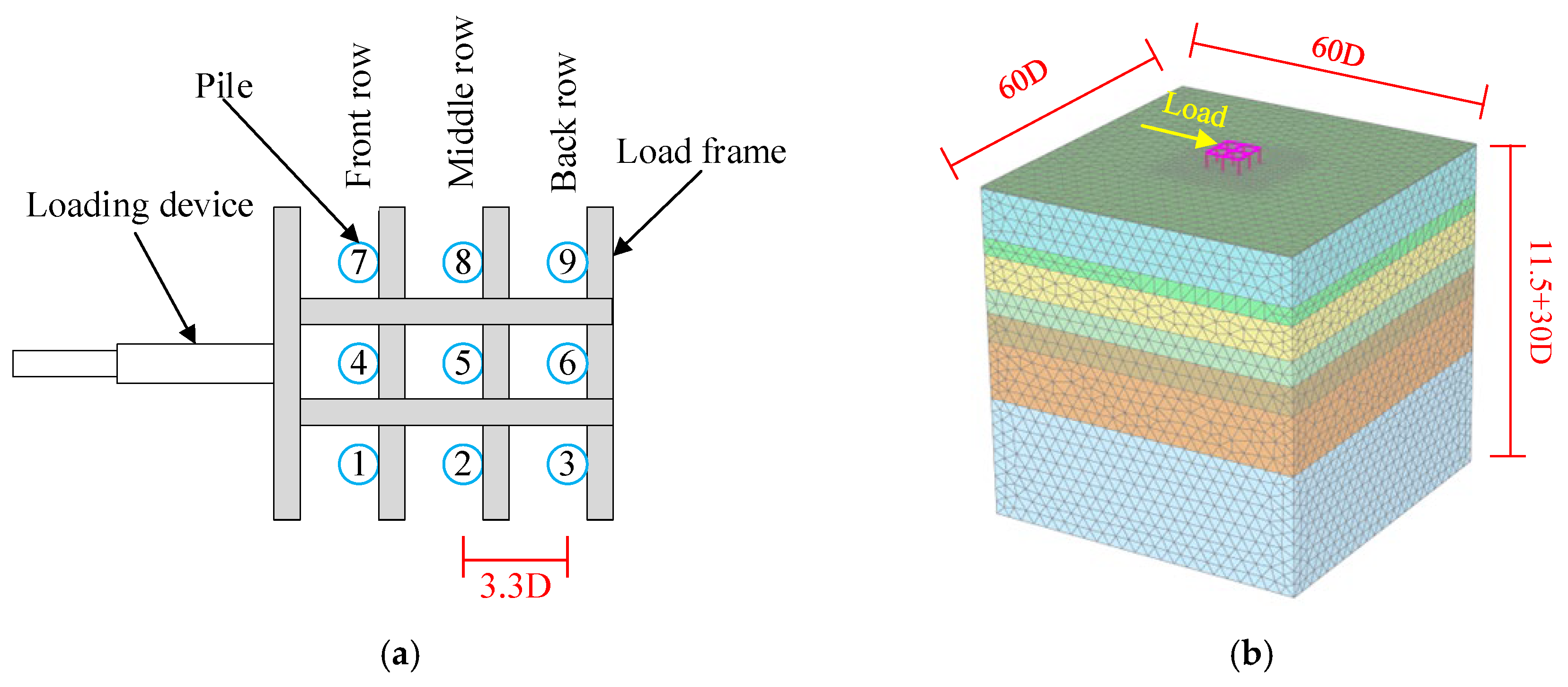
2.1. Introduction to the Field Test

Rollins et al. [30] conducted a series of in situ horizontal load tests to investigate the group interaction effects of pile foundations under horizontal loading conditions. The experimental configuration comprised nine steel pipe piles arranged in a 3 × 3 matrix configuration with a pile diameter (D) of 0.324 m and a pile spacing (S) of 3.3D. The moment of inertia of each pile was 1.43 × 10⁸. The pile group featured an embedment depth of 11.5 m within the soil stratum and maintained a free-standing segment of 0.86 m above ground level to accommodate the lateral load. The loading device was a rigid frame beam, which was hinged to prevent the transfer of bending moments to the pile top. Lateral loading was applied using an electric hydraulic servo system. The test setup is described in Figure 1a.
The soil strata at the test site consists of eight layers, primarily composed of sand and soft clay. The cone penetration test (CPT) and the standard penetration test (SPT) were employed to evaluate the natural soil in the in situ soil layers. The geotechnical characteristics of the soil, using the American Petroleum Institute (API) method and the Bolton method, are presented in Table 1. During the test period, the groundwater level was located 0.1 m below the ground.

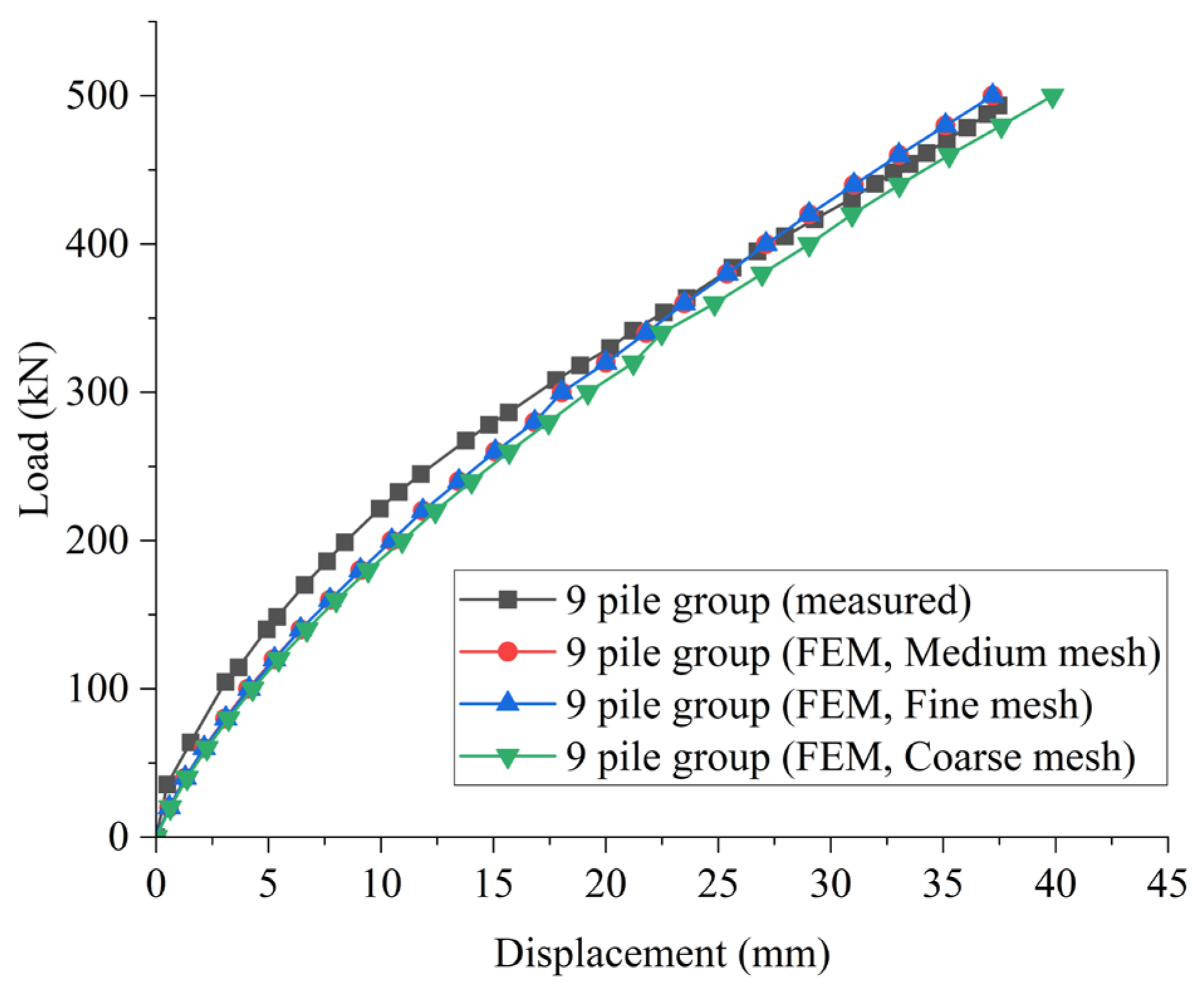
2.2. Reliability Verification of the Numerical Model

Based on field tests of horizontal load-bearing capacity conducted by Rollins et al. [30], a finite element model was established using Plaxis 3D V2023.2. The model was compared with the field test results to validate its effectiveness for analyzing the pile groups under horizontal loading in this study. According to the research by Dong et al. [31], horizontal boundaries exert a significant influence on the lateral bearing capacity of piles, with the recommended minimum distance from boundary to pile center exceeding 15 times the pile diameter. In contrast, vertical boundaries have relatively minor effects on lateral load-bearing performance. Jones et al.’s [32] numerical investigation of 3 × 3 pile groups established vertical boundaries at 10D below pile tips and horizontal boundaries at 30D from the pile group periphery, demonstrating that the boundary effects on the numerical analysis outcomes were negligible. Hence, in this study, the boundary of the model was set at a distance of 30D from the center of the pile group and 30D from the base of the pile. To maintain consistency with field conditions, concentrated point loads were applied at nodal positions corresponding to the physical loading points in the field test. The finite element model is presented in Figure 1b.
The constitutive model for the soil utilizes the Hardening Soil (HS) model, which simulates the stress-dependence of the soil stiffness among other factors [33]. The E 50 ref in the HS model can be calculated using Equations (1) and (3), while E oed ref and E ur ref can be calculated using Equations (2) and (4) [34].
For sandy soil,
E 50 ref = 15000   to   22000 ln N
E ur ref = 3 E oed ref = 3 E 50 ref
For clayey soil,
E 50 ref = 3   to   8 q c
E ur ref = 5 E oed ref = 5 E 50 ref
The constitutive parameters for the HS model are shown in Table 2.
Each pile is assumed to be linearly elastic [35,36], and the piles are modeled using embedded beams, which reduces the complexity of the numerical model without compromising its accuracy. Existing case studies have demonstrated the quality and advantages of this modeling method [37]. The interface reduction coefficient, Rinter, is set to 0.67 to represent the interface between the pile cap and the soil [38,39]. Given the horizontal ground surface, the initial geo-stress balance is achieved using the built-in K0 procedure in PLAXIS. In the finite element model, the mesh is refined for the pile, surrounding soil, and pile cap.
A mesh independence verification is also performed to ensure that the results are independent of the mesh size. The mesh independence analysis was conducted through three distinct mesh configurations (coarse, medium, and fine meshes), as illustrated in Figure 2. The medium and fine meshes yield nearly identical solutions, whereas the coarse mesh exhibits significantly larger discrepancies. To optimize the balance between computational efficiency and numerical accuracy, the medium mesh is adopted for all subsequent analyses, ensuring that the simulation outcomes remain unaffected by mesh discretization errors while maintaining reasonable computational demands.
The horizontal displacement of the pile group and the bending moment of the piles obtained from the field tests are compared with the finite element simulation results to validate the effectiveness of the finite element method. Figure 2 depicts the load–displacement curve comparison for the pile cap, while the bending moment verification results for the central pile in the front row at different loading displacements are shown in Figure 3. The calculated FEM values closely match the values recorded in the experiments. Therefore, the finite element model demonstrates high validity and can be further applied in subsequent research.

3. Horizontal Load Response Analysis of the Pile Group with a Pile Cap

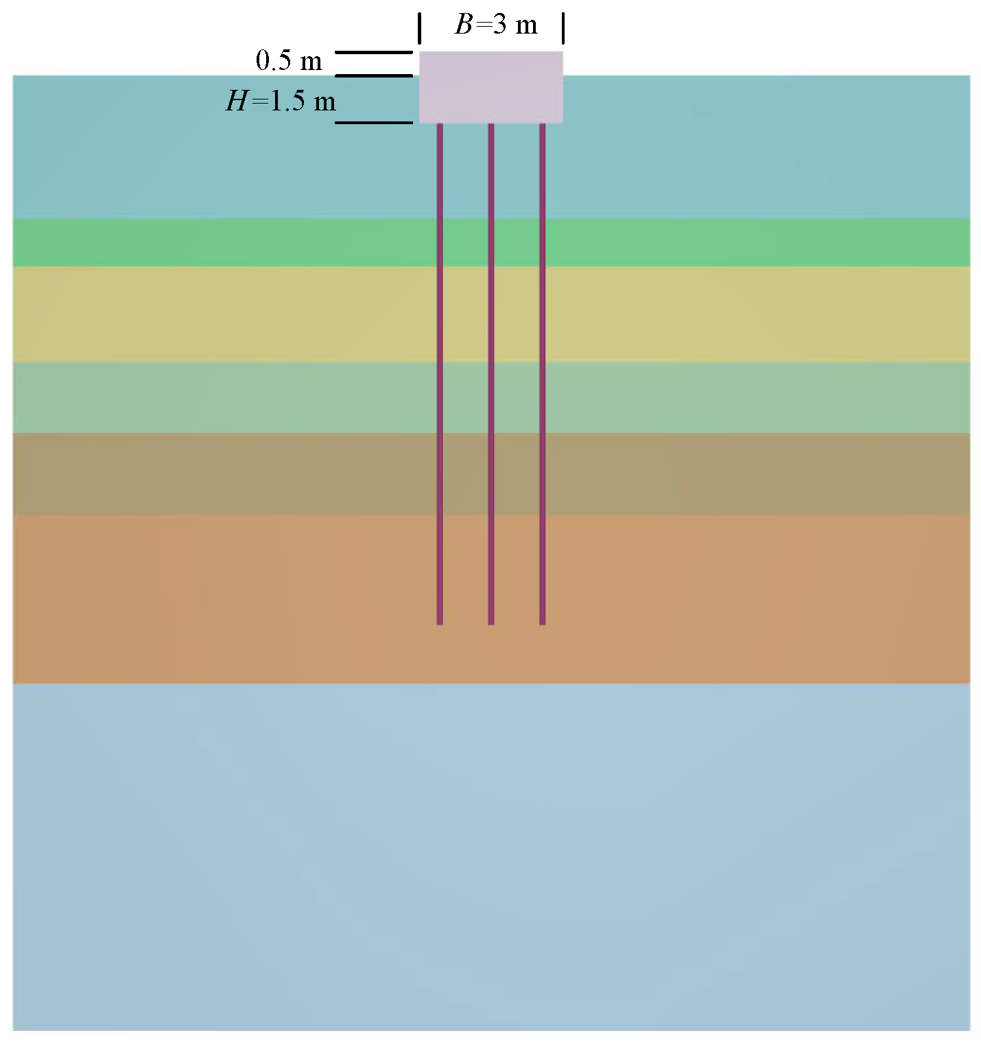
3.1. Establishment of the Finite Element Model

Building upon the pile group without a cap, an enhanced numerical model integrating a pile cap was developed, as illustrated in Figure 4. The cap geometry was defined with plan dimensions of L = 3.0 m (length) and B = 3.0 m (width). The structural profile of the pile cap comprised two parts: a 0.5 m thick superstructure protruding above the ground and a 1.5 m deep substructure embedded below the surface, resulting in a total vertical dimension of 2.0 m. To accurately simulate soil–structure interactions, interface elements with a reduction factor of Rinter = 0.67 were implemented along all lateral faces and the base of the pile cap. The loading protocol adopted a load-controlled approach, applying horizontal forces in increments, from 150 kN to 1350 kN in 150 kN steps. This facilitated both the preservation of pile deformations within the elastic regime and the acquisition of sufficient experimental data points for analysis.

3.2. The Impact of the Pile Cap on the Horizontal Load Bending Characteristics of the Pile Group

3.2.1. The Load–Displacement Curve

Figure 5 depicts the load–displacement curves under horizontal loading. The curve for the pile group with a cap exhibits smoother progression, reflecting more uniform deformation development and enhanced stability throughout the loading process. Notably, the pile group with a cap achieves a maximum applied load of 900 kN, representing a 50% increase in bearing capacity. This substantial improvement can be attributed to the cap’s role in bearing part of the horizontal load and promoting synergistic interaction within the pile group. At equivalent load levels, the horizontal displacement for the pile group with a cap is reduced by 59.5% on average. For instance, under a 450 kN load condition, the pile group with no cap demonstrates 33 mm of displacement, whereas the other maintains a displacement of 4.6 mm. This marked contrast underscores the pile cap’s dual mechanism of action, as it not only bears the horizontal load but also enhances the system’s flexural rigidity through composite action between the cap and piles. These findings quantitatively validate the pile cap’s critical contribution to improving lateral resistance capacity while maintaining serviceability requirements under extreme loading scenarios.

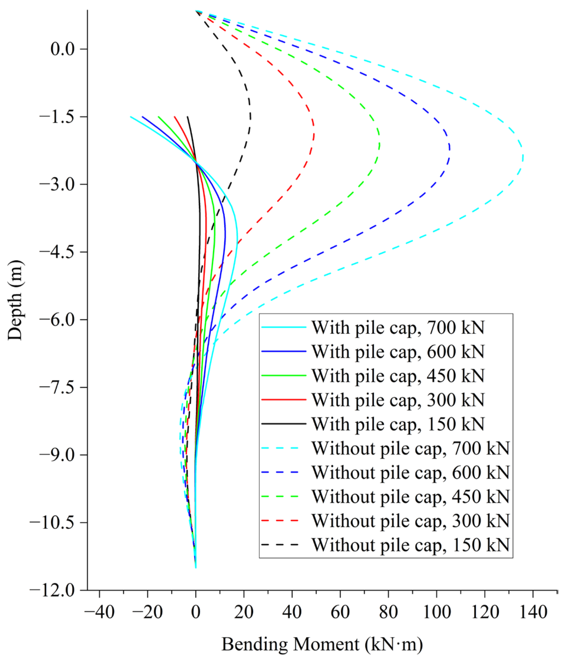
3.2.2. The Impact of the Pile Cap on the Bending Moment of Piles in the Pile Group

Figure 6 illustrates the bending moment distribution versus depth for the center pile in the front row in the capped and uncapped pile groups under five distinct load levels (150 kN to 700 kN). For the pile group without a pile cap, the bending moment at the pile head is zero. In contrast, the pile develops measurable bending moments at the pile head due to the rigid cap–pile connection, which facilitates moment transfer [29]. Under identical loading conditions (e.g., 700 kN lateral load), capped configurations exhibit a substantial reduction in maximum bending moment: uncapped piles achieve a peak of 136 kN·m, whereas capped piles reach a significantly lower 18 kN·m peak, representing an 86% reduction. These results confirm that pile caps not only mitigate peak bending moments but also redistribute flexural demands along the pile shafts.

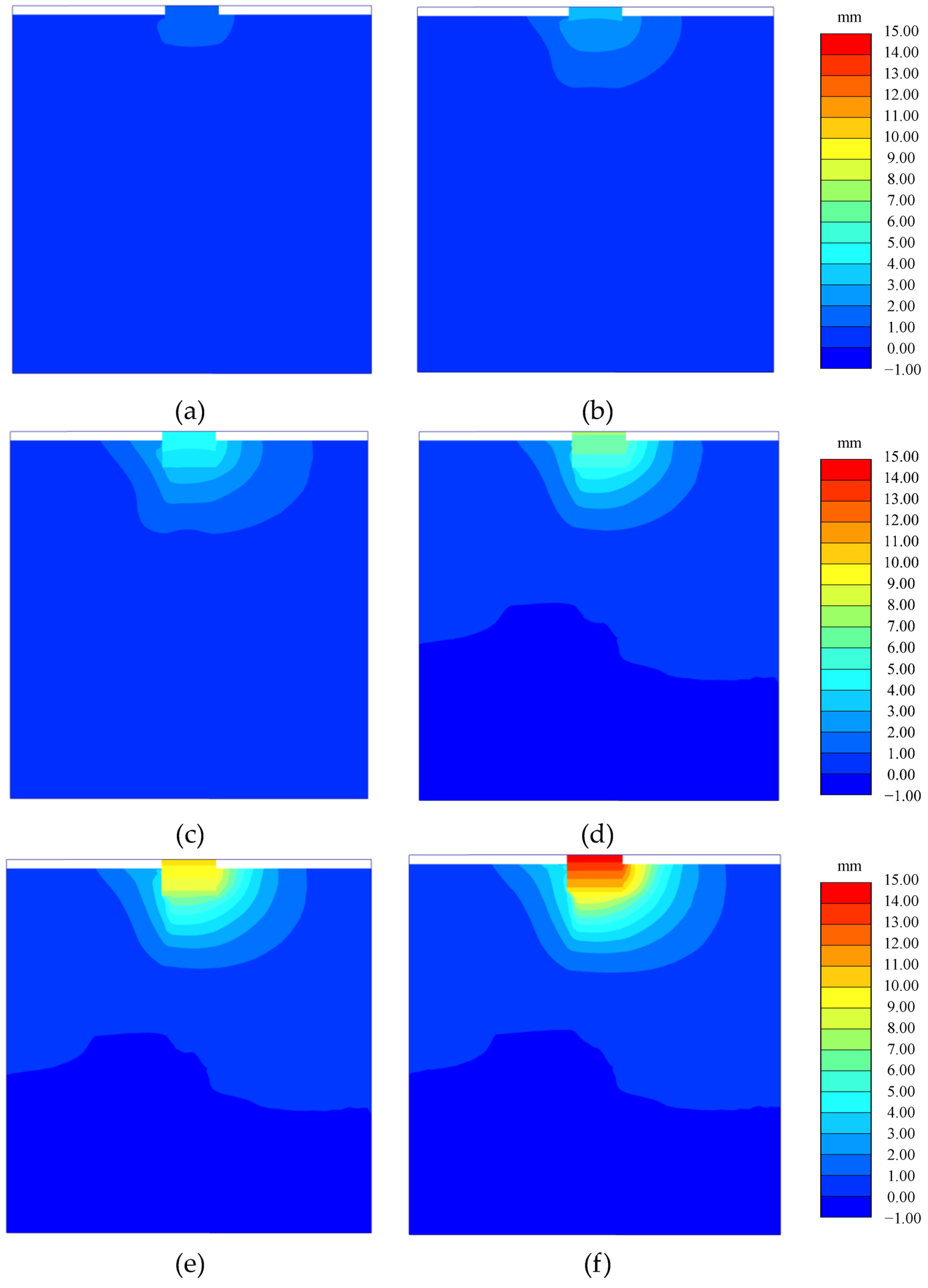
3.2.3. Horizontal Displacement of the Pile Cap

Figure 7 presents the contour plots of horizontal displacement for the pile group at various load levels. At lower load stages (e.g., configurations in Figure 7a,b), localized displacement concentrations emerge near the pile cap–soil interface, which is primarily governed by pile cap rigidity. As loading intensifies (Figure 7c–f), the displacement contours develop pronounced asymmetry, reflecting a redistribution of the load from the pile cap to the piles. The pile cap initially mobilizes its friction to resist early-stage loading, as evidenced by the minimal soil displacement that occurs outside the immediate vicinity of the pile cap. Upon exceeding a threshold load level (approximated in Figure 7c), the system transitions to a pile resistance phase, during which bending-induced pile deformations generate shear stresses along the pile–soil interface, triggering progressive soil displacement that propagates radially around individual piles and coalesces into a composite displacement field. This load-dependent displacement pattern substantiates the pivotal role of the pile cap in resisting lateral loads. The progressive propagation of displacement into deeper soil strata further corroborates that horizontal loads are initially mobilized by the pile cap, subsequently transitioning to a combined resistance mechanism that involves both the pile cap and piles.

3.2.4. Load Sharing on the Pile Cap

For pile groups subjected to horizontal loads, the load is carried by both the pile cap and the piles. The horizontal resistances provided by the cap and the piles are denoted as PC and PP, where subscript letters C and P represent the cap and piles, respectively. Figure 8 depicts the load sharing between the pile cap and piles under different loads. As shown in Figure 8, in the initial loading stage (with relatively low load), the load carried by the cap (PC) constitutes a large proportion (approximately 62%), while only 38% of the load is borne by the piles (PP) [28]. As the load increases, the attributed load to the pile cap gradually decreases, while the load borne by the piles increases; together, they share approximately 50% of the load. This finding is consistent with Ashour et al.’s work [13], wherein the pile cap accounted for approximately 50% of the total lateral resistance in the pile group–cap system. Therefore, the cap can effectively bear the horizontal load, which helps improve the horizontal bearing capacity.
Figure 9 shows a diagram of the lateral resistance of the pile cap embedded in soil under horizontal loading. The lateral resistance of the pile cap PC has three main sources:
(1) The passive earth pressure of the soil at the front of the cap PC-E.
(2) The frictional force between the bottom of the cap and the soil PC-B.
(3) The frictional force between the sides of the cap and the soil PC-S.
The lateral resistance of each part of the cap can be obtained through numerical integration of the set interface in Plaxis 3D. Figure 10 shows the three-part lateral resistance of the pile cap. As the load levels increase, the total soil resistance of the cap, the lateral resistance from the passive earth pressure at the front, the bottom friction, and the side friction increase concurrently (though gradually), but the passive earth pressure at the front approaches a stable value. The increase in passive earth pressure is significantly higher than that of the bottom and side friction. Figure 10 shows that at different load levels, the lateral resistance provided by the PC-E accounts for the largest proportion, reaching 72–80%. The lateral resistance provided by the PC-B accounts for the second largest proportion, reaching 15–18%. The lateral resistance provided by the PC-S is the smallest, accounting for only 5–12%. Therefore, the passive earth pressure at the front of the cap is the main source of lateral resistance. However, the lateral resistance from friction at the bottom and sides of the cap, though relatively small, is still notable.

4. Parametric Studies

To comprehensively investigate the load sharing of the pile cap under the lateral load. This involved varying two critical design parameters: cap width (B) and embedment depth (H). This analysis aims to quantify the effects of these geometric variables on both the lateral deformation characteristics of the pile group and the proportion of the load that is shared between the pile cap and piles. Building upon the validated finite element model presented in Section 3, a series of numerical simulations were executed with controlled parameter variations while maintaining consistent soil stratification and pile properties. The cap embedment depth was systematically increased from 0.5 m to 3.0 m at 0.5 m intervals (H = 0.5, 1.0, 1.5, 2.0, 2.5, 3.0 m), while the cap width was incrementally expanded from 2.5 m to 3.5 m in 0.5 m increments (B = 2.5, 3.0, 3.5 m).

4.1. The Embedment Depth of the Cap

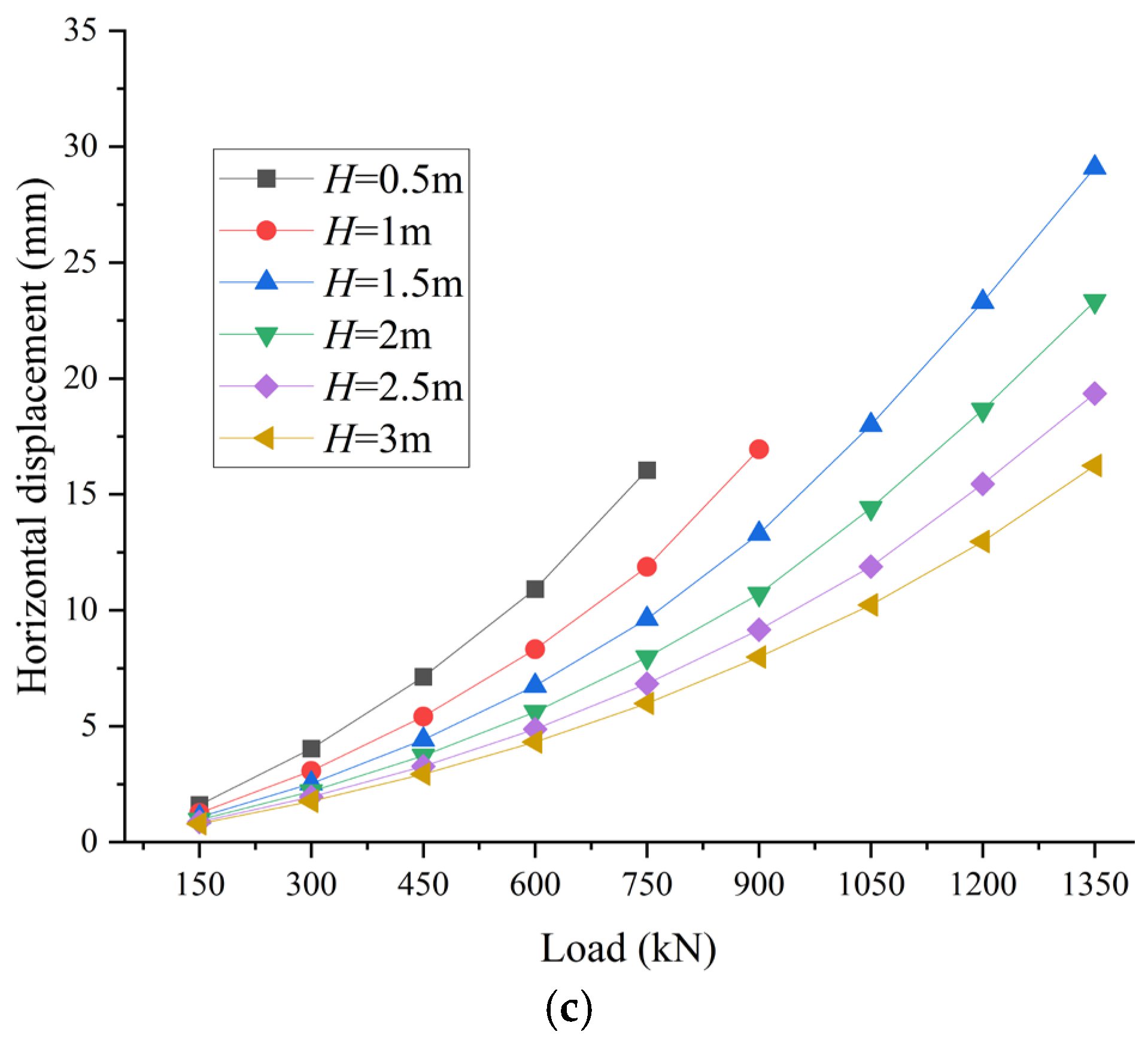
4.1.1. The Load–Displacement Curve

Figure 11 presents the load–horizontal displacement curves at the top center of the cap for different embedment depths. As shown in Figure 11, the horizontal displacement increases nonlinearly with the load, and not all of the curves exhibit a distinct inflection point. Additionally, when the load level is constant, the horizontal displacement decreases as the embedment depth H of the cap increases. This indicates that a greater cap embedment depth of the cap reduces the horizontal displacements of the pile group and enhances the bearing capacity.

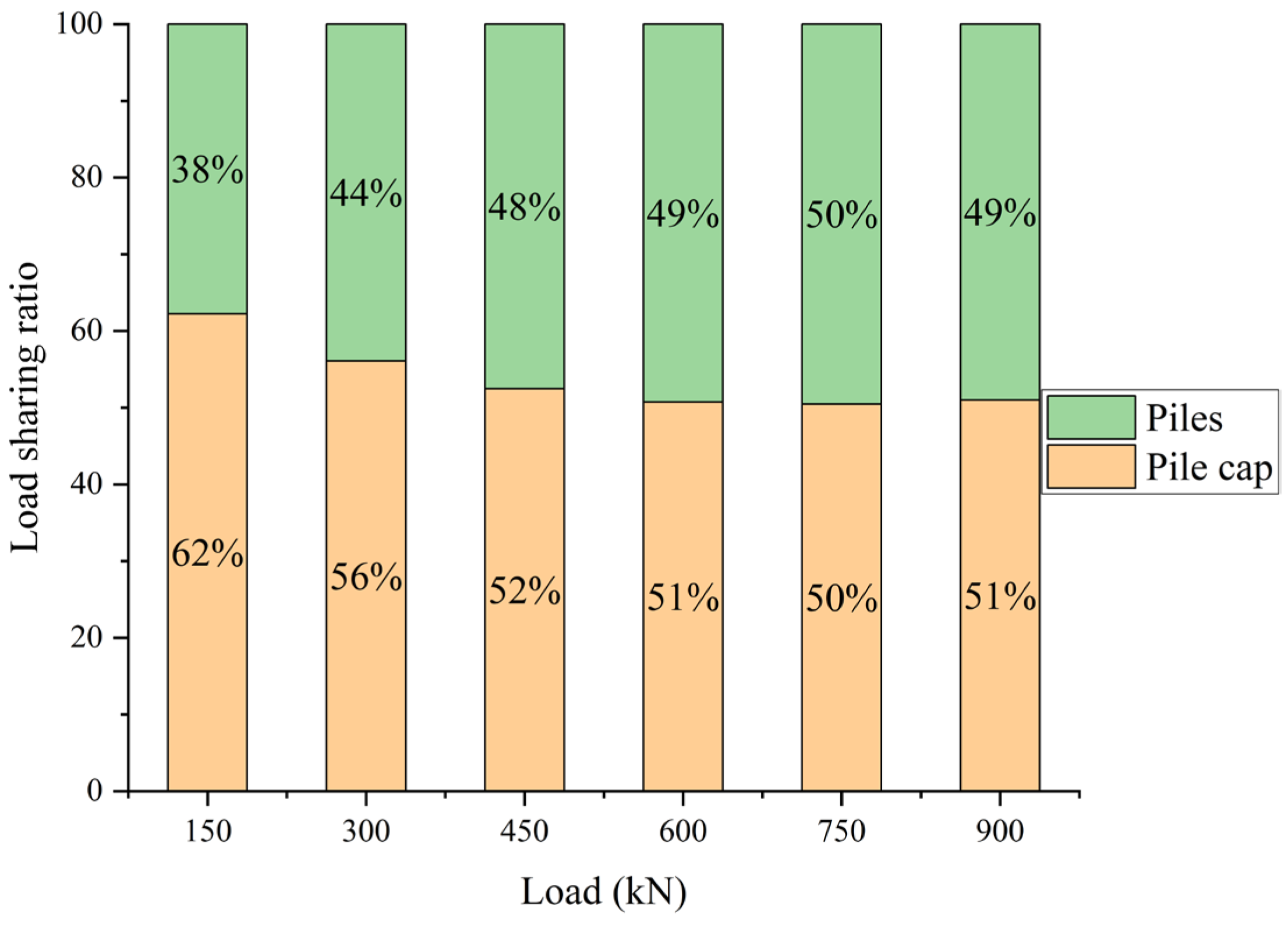
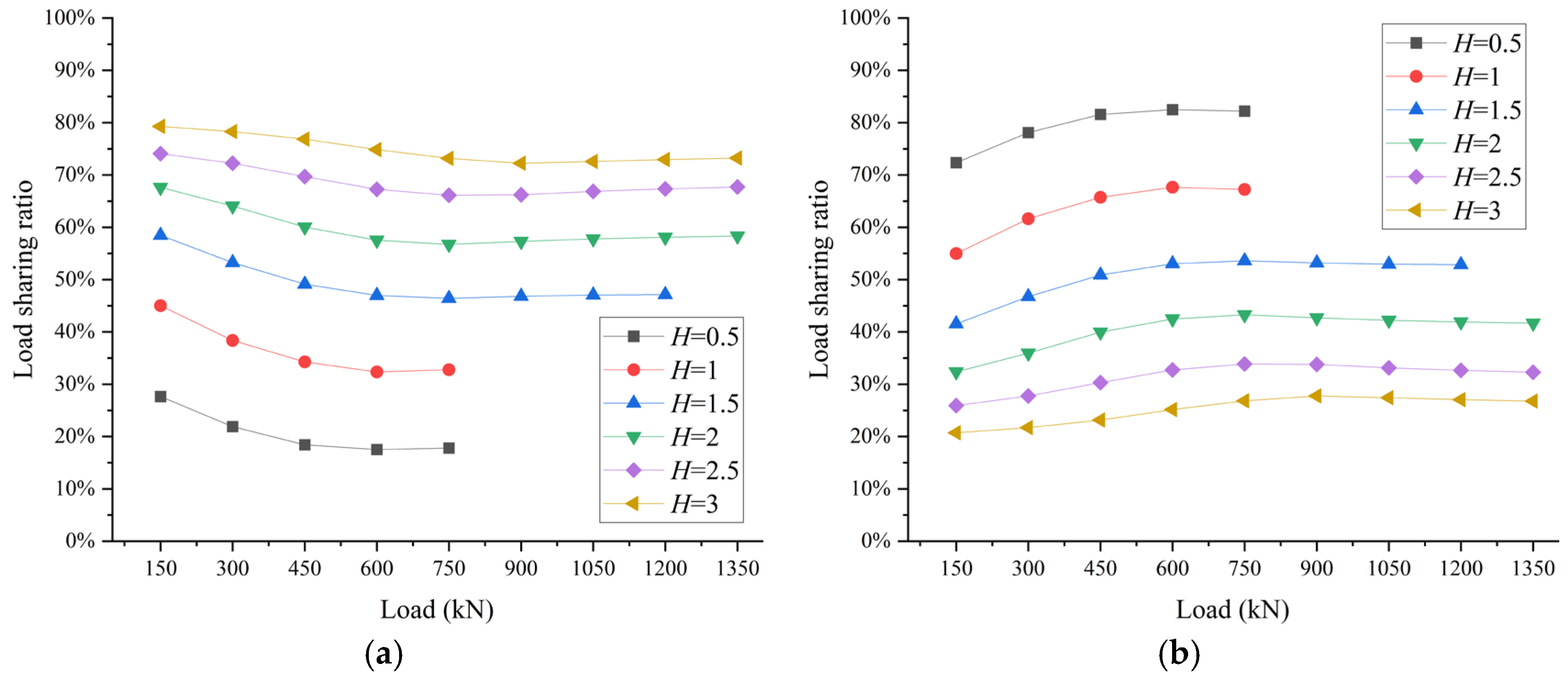
4.1.2. Load Sharing on the Pile Cap and Piles

Figure 12, Figure 13 and Figure 14 depict the load-sharing ratios for different embedment depths. As observed in Figure 12, as the load increases, the load-sharing ratio of the pile cap gradually decreases, while the load ratio of the piles shows a gradual decrease. This indicates that, at lower load levels, the cap initially resists horizontal forces, and as the load increases, the piles begin to bear more of the horizontal load.
For different cap widths, the load shared by the cap increases with the embedment depth. This is due to the fact that as the embedment depth increases, the area at the front also increases, leading to a larger amount of passive earth pressure, which provides greater horizontal resistance. The results demonstrate that amending the embedment depth of the pile cap from 0.5 m to 3.0 m significantly improves load distribution efficiency, elevating the pile cap’s load-sharing ratio from approximately 20% to 80%.

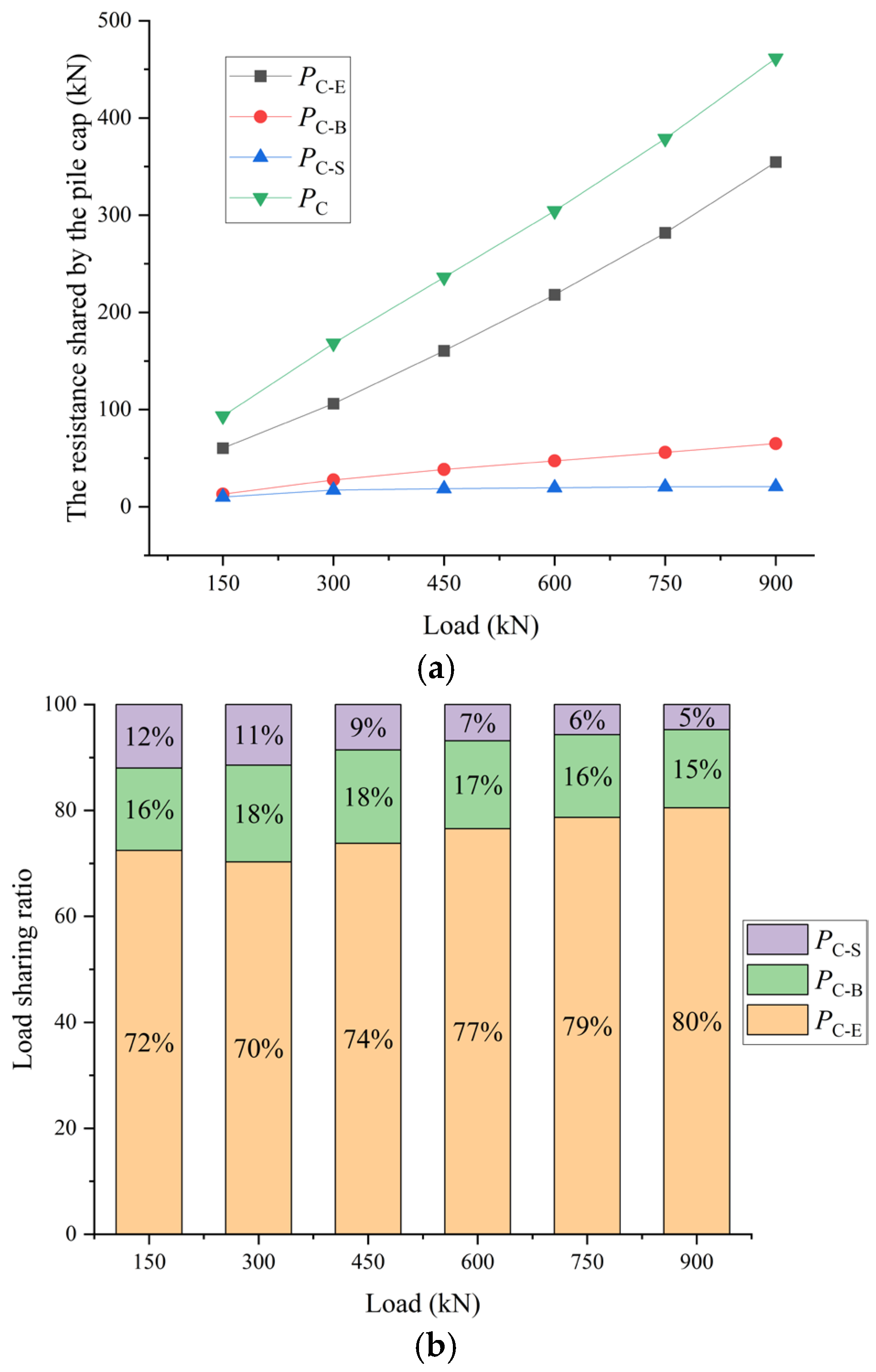
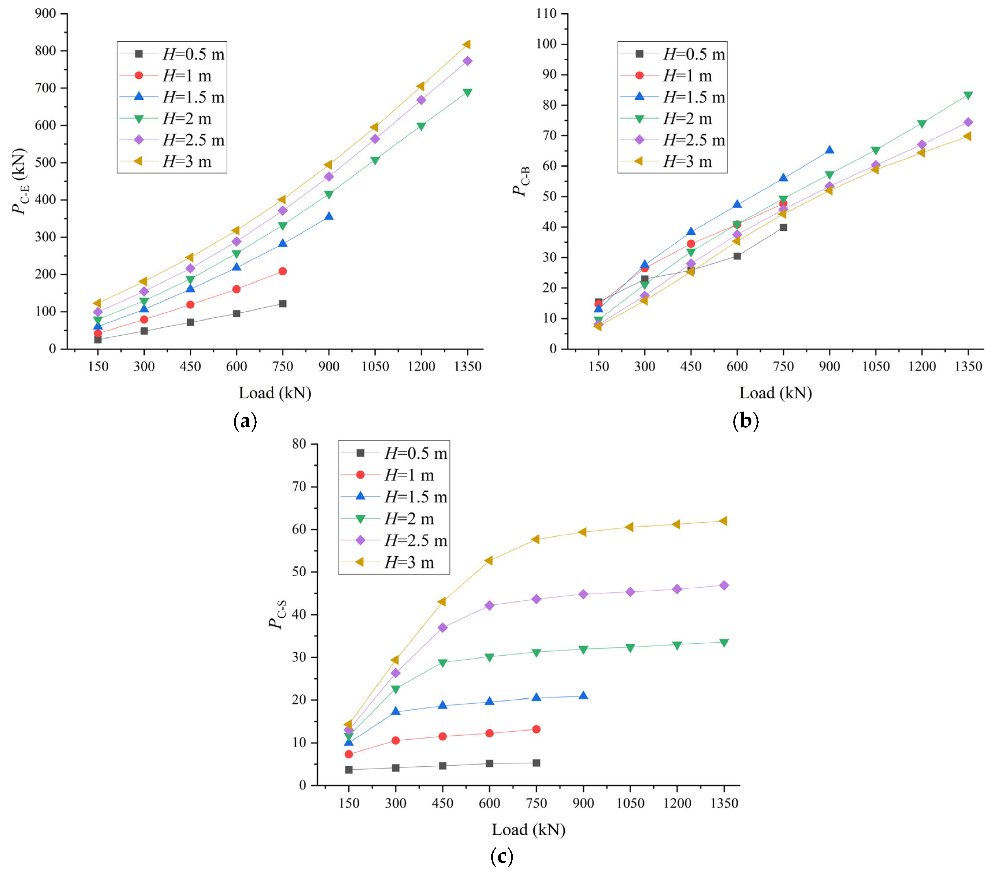
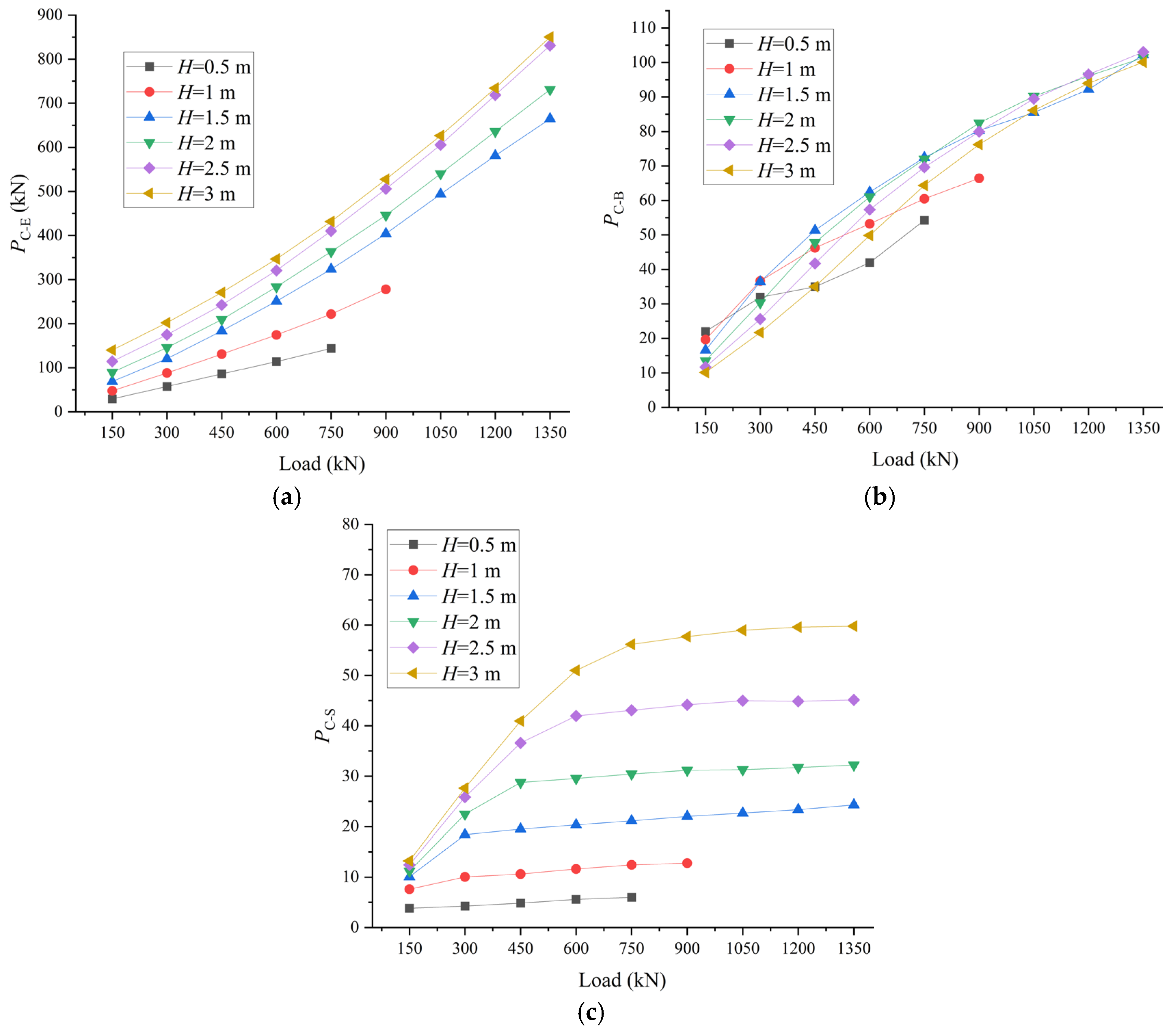
4.1.3. Load Sharing Among Different Parts of the Pile Cap

Figure 15, Figure 16 and Figure 17 illustrate the load distribution among different parts of the cap for various embedment depths at different cap widths. As shown in Figure 17, under different embedment depths, the load-sharing ratios of the pile cap, denoted as PC-E, PC-B, and PC-S, gradually increase with the lateral load, but once they reach a certain threshold, they remain relatively constant. For a given load, as the embedment depth increases, the values of PC-E and PC-S also increase, which suggests that increasing the embedment depth helps to enhance PC-E and PC-S. However, for PC-B, the relationship with embedment depth is less significant. This is because when the cap is subjected to horizontal loads, it undergoes some degree of rotation, causing separation between the cap base and the soil, which influences PC-B.

4.2. The Width of the Cap

The data for pile cap widths of 2.5 m, 3.0 m, and 3.5 m (with an embedment depth of 1.5 m) were used to compare the response of the horizontal load to variations in cap width.

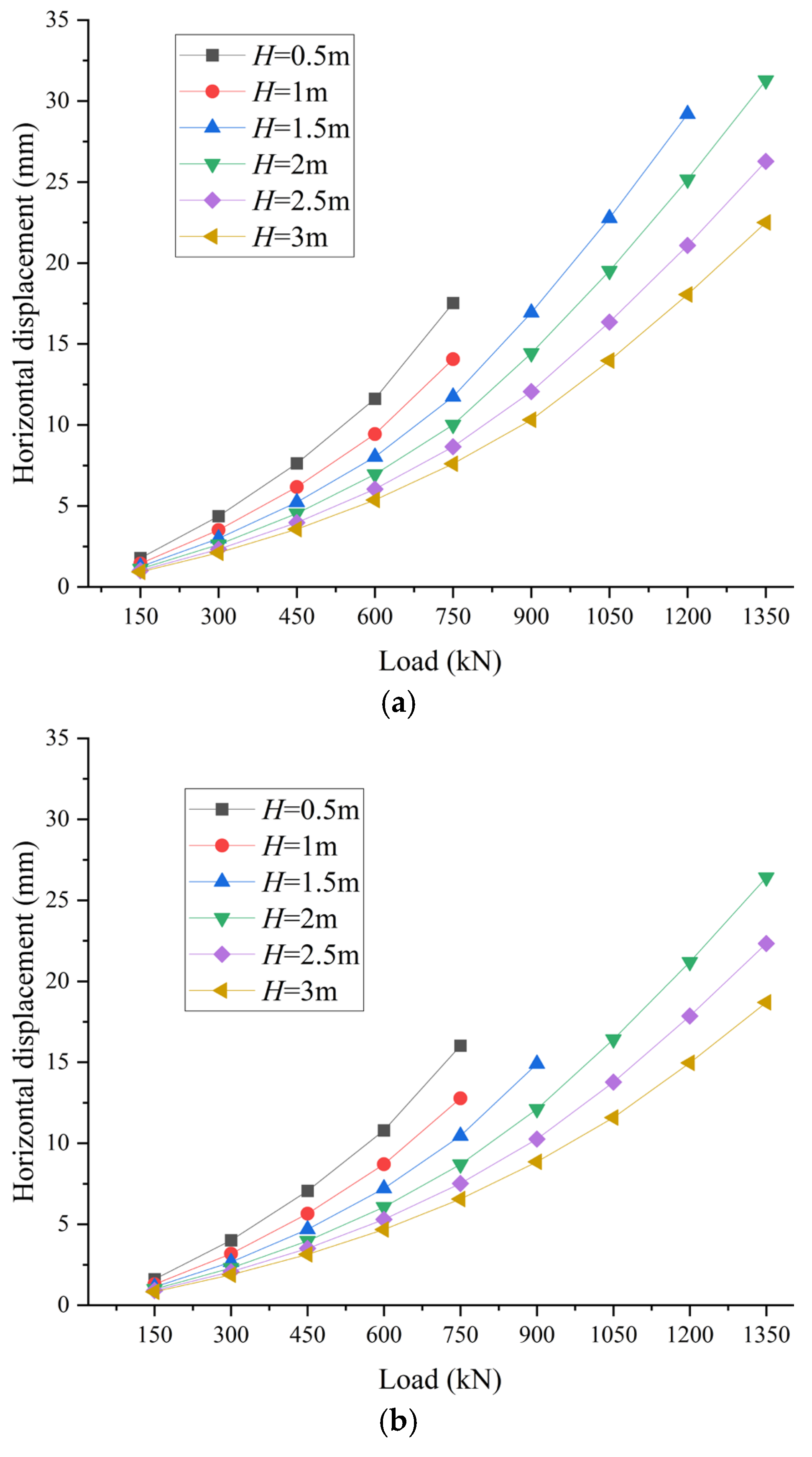
4.2.1. The Load–Displacement Curve

Figure 18 shows the load–horizontal displacement curve of the pile group with a pile cap embedment depth of 1.5 m. Figure 18 shows a positive correlation between the lateral load-bearing capacity of the pile group and the enlargement of the pile cap width, with the former exhibiting enhancement as the latter is incrementally expanded. Under a constant load level, the horizontal displacement decreases as the pile cap width increases, suggesting that when the embedment depth is unchanged, increasing the pile cap width reduces the horizontal displacement and enhances the horizontal bearing capacity.

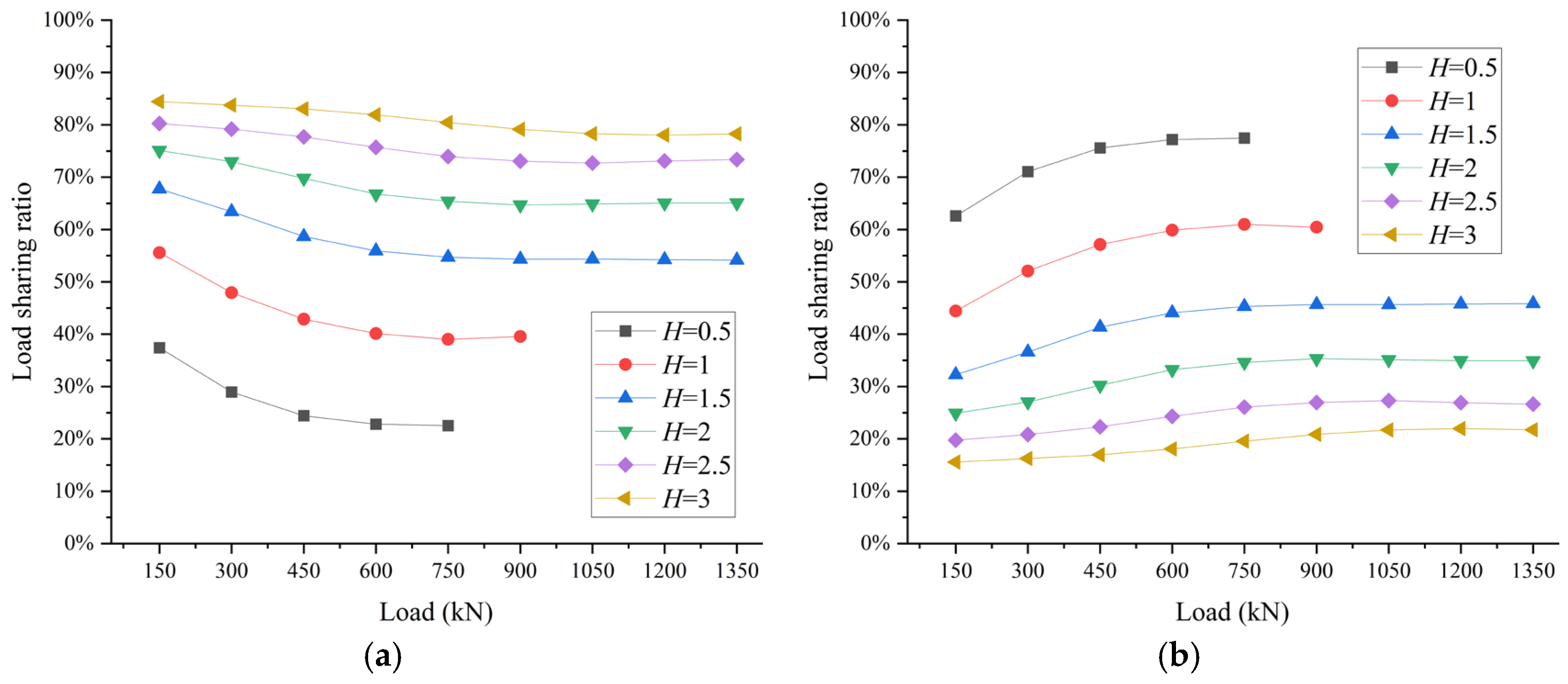
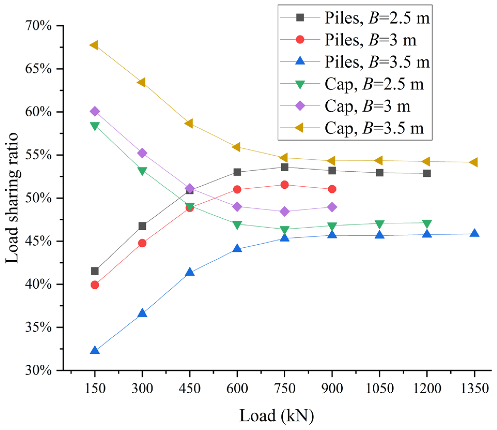
4.2.2. Load Sharing on the Pile Cap and Piles

Figure 19 shows the load-sharing ratios under different pile cap widths. As the pile cap width increases, the proportion of load borne by the pile cap also increases. This is because increasing the pile cap width effectively increases its volume and area, providing greater horizontal resistance. Furthermore, under different load conditions, the amount of load borne by the cap is always greater than that borne by the piles. When the pile cap width is constant, the proportion of load borne by the pile cap gradually decreases as the load increases, while the piles exhibit the opposite trend. Eventually, the load distribution ratio stabilizes.

4.2.3. Load Sharing Among Different Parts of the Pile Cap

Figure 20 shows the variation in the horizontal resistance of the three parts of a pile cap at a depth of 1.5 m with a load and with different pile cap widths. Figure 20 demonstrates that increasing the width helps improve the resistance of PC-E and PC-B, while the resistance of PC-S is not sensitive to such increase. This is because increasing the width changes the bottom and top areas of the pile cap, while the resistance of PC-E and PC-B is provided by the frictional forces at the bottom and top surfaces. The side area of the cap is independent of its width; thus, the resistance of PC-S does not change significantly with different widths. In addition, we also compared the response to horizontal loads and the load-sharing ratio for different pile cap widths under other pile cap depths, observing similar trends to those noted at a pile cap depth of 1.5 m.

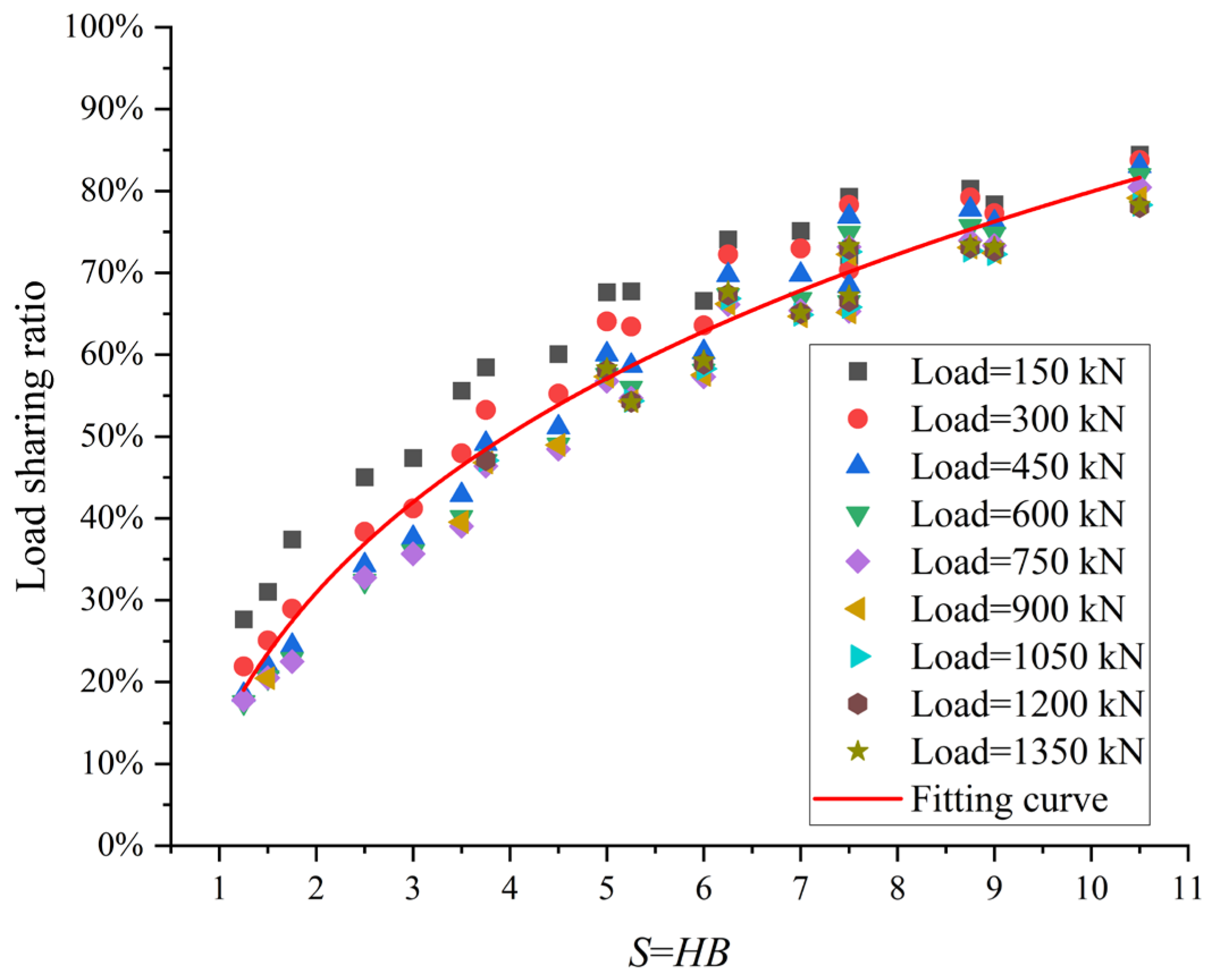
4.3. The Relationship Between the Load-Sharing Ratio and HB

The pile cap primarily resists horizontal loads through the frictional forces between its sides and bottom surfaces and the surrounding soil, as well as the passive soil pressure exerted at its front. Both the passive soil pressure and frictional forces are directly proportional to the area. Therefore, we investigate the relationship between the load distribution ratio (β) of the pile cap and the product of the pile cap’s embedding depth and width, S = HB, under varying horizontal loads, as illustrated in Figure 21. The load distribution ratio increases nonlinearly with the increase in S. This relationship can be accurately modeled using the following function with an R2 value of 0.94, indicating a high degree of fit.
β = P C P C + P P = 0.85 + S 0.22

5. Conclusions

In this study, we systematically investigated the finite element method to investigate the displacement and load-sharing behavior of a 3 × 3 pile group foundation with a pile cap under horizontal loading. The main conclusions are as follows:
(1) The pile cap embedded in the soil enhanced the bearing capacity of the pile group and reduced the horizontal displacement. The pile cap initially bore 62% of the total lateral load at low loading stages, which decreased to 50% at higher loads, while the pile contribution inversely increased from 38% to 50%.
(2) The horizontal resistance of the pile cap originated from three primary sources: passive earth pressure from the soil in front of the pile cap (PC-E) and frictional forces on the bottom and sides of the pile cap (PC-B and PC-S). The passive earth pressure (PC-E) plays the most significant role, contributing 72–80% of the total cap resistance.
(3) For a fixed pile cap width, an increase in pile cap burial depth resulted in a greater provision of horizontal resistance from the pile cap. Increasing the embedment depth (H) from 0.5 m to 3.0 m elevated the pile cap’s load-sharing ratio by approximately 60%. Both PC-E and PC-B increased with the load, while PC-S stabilized as the load increased.
(4) When the pile cap depth was constant, an increase in pile cap width led to a horizontal resistance pattern similar to that observed with increasing pile cap depth.
(5) The load-sharing ratio of the pile cap (β) increased with the increase in S = HB, following a power function relationship.

Author Contributions

Conceptualization, Y.R., Z.C. and W.Z.; methodology, Y.R., Z.C. and W.Z.; software, Z.C.; validation, Y.R. and Z.C.; formal analysis, Y.R. and Z.C.; investigation, Y.R. and Z.C.; resources, W.Z.; data curation, Y.R. and Z.C.; writing—original draft preparation, Y.R. and Z.C.; writing—review and editing, Y.R., Z.C. and W.Z.; visualization, Y.R. and Z.C.; supervision, W.Z.; project administration, Z.C. and W.Z.; funding acquisition, W.Z. All authors have read and agreed to the published version of the manuscript.

Funding

This research was funded by the National Natural Science Foundation of China, 52208333, and the Research Fund for Advanced Ocean Institute of Southeast University, General Program GP202403.

Data Availability Statement

The original contributions presented in this study are included in the article. Further inquiries can be directed to the corresponding author.

Acknowledgments

The authors would like to thank Rollins KM, Lane JD, and Gerber TM for their outstanding work, which has provided invaluable reference data for the validation of this study.

Conflicts of Interest

The authors declare no conflicts of interest.

References

  1. Ates, B.; Şadoğlu, E. Experimental investigation of optimum piles spacing for piled raft foundation in sandy soils. Tek. Dergi 2021, 32, 10477–10494. [Google Scholar] [CrossRef]
  2. Basha, A.; Elmorsy, S.; Mansour, W.; Ramadan, B. Effect of the pile cap length and the soil relative density on the pile cap–pile–dense soil interaction: Experimental investigation. Case Stud. Constr. Mater. 2024, 20, e03169. [Google Scholar] [CrossRef]
  3. Mostafa, Y.E.; Naggar, M.H.E. Dynamic analysis of laterally loaded pile groups in sand and clay. Can. Geotech. J. 2002, 39, 1358–1383. [Google Scholar] [CrossRef]
  4. Munawir, A.; Harimurti; Sumarsono, Q.A.R.P. Lateral Load Capacity and p-Multiplier of Group Piles with Asymmetrical Pile Cap under Seismic Load. Appl. Sci. 2022, 12, 8142. [Google Scholar] [CrossRef]
  5. Chen, Z.; Deng, H.; Dai, G.; Zhu, M.; Gong, W.; Azadi, M.R. Study on the influence of unsymmetrical surcharge on adjacent pile foundations in a coastal soft soil area. Soil Dyn. Earthq. Eng. 2025, 194, 109365. [Google Scholar] [CrossRef]
  6. Unsever, Y.S.; Matsumoto, T.; Özkan, M.Y. Numerical analyses of load tests on model foundations in dry sand. Comput. Geotech. 2015, 63, 255–266. [Google Scholar] [CrossRef]
  7. Deb, P.; Pal, S.K. Numerical analysis of piled raft foundation under combined vertical and lateral loading. Ocean Eng. 2019, 190, 106431. [Google Scholar] [CrossRef]
  8. Ateş, B.; Şadoğlu, E. Experimental investigation for group efficiency of driven piles embedded in cohesionless soil. KSCE J. Civ. Eng. 2023, 27, 5123–5134. [Google Scholar] [CrossRef]
  9. Bandyopadhyay, P.; Teng, F. Analysis of pile-soil-excavation interaction and load transfer mechanism in multi-layered soil for an in-service pile group. Comput. Geotech. 2024, 171, 106378. [Google Scholar] [CrossRef]
  10. Wu, T.; Gao, Y.; Huang, C.; Zhou, Y.; Li, J. Mechanical Behavior of Single and Group Piles with a Low Cap Adjacent to Shield Tunneling in Composite Ground: Insights from Centrifugal Model Testing. Geotech. Geol. Eng. 2024, 42, 7451–7480. [Google Scholar] [CrossRef]
  11. Ateş, B.; Şadoğlu, E. Experimental investigation of pile addition and length on bearing capacity and settlement of rafts on loose sandy soil. Afyon Kocatepe Üniv. Fen Ve Mühendis. Bilim. Derg. 2021, 21, 399–407. [Google Scholar]
  12. Jeong, S.-S.; Won, J.-O.; Kim, Y.-H. Effect of pile cap flexibility on the response of pile group supported column. J. Korean Geotech. Soc. 2007, 23, 39–49. [Google Scholar] [CrossRef]
  13. Ashour, M.; Abbas, A.I.; Boskovic, S. Pile Cap Interaction with Bridge Pile Foundations under Lateral Loads. J. Bridge Eng. 2019, 24, 04019053. [Google Scholar] [CrossRef]
  14. Varghese, R.; Boominathan, A.; Banerjee, S. Stiffness and load sharing characteristics of piled raft foundations subjected to dynamic loads. Soil Dyn. Earthq. Eng. 2020, 133, 106117. [Google Scholar] [CrossRef]
  15. Zhong, C.; Chen, Z.; Zhou, J. Numerical Investigations of Pile Group Foundations under Different Pile Length Conditions. Appl. Sci. 2024, 14, 1908. [Google Scholar] [CrossRef]
  16. Qiu, H.; Wang, H.; Ayasrah, M.M.; Zhou, Z.; Li, B. Study on Horizontal Bearing Capacity of Pile Group Foundation Composed of Inclined and Straight Piles. Buildings 2023, 13, 690. [Google Scholar] [CrossRef]
  17. Jamil, I.; Ahmad, I.; Rehman, A.U.; Siddiqi, M.I.; Ahmed, A.; Khan, A.M. Piles’ load distribution in pile raft and pile group under lateral loading. Mar. Georesour. Geotechnol. 2024, 42, 1034–1049. [Google Scholar] [CrossRef]
  18. Won, J.; Ahn, S.Y.; Jeong, S.; Lee, J.; Jang, S.Y. Nonlinear three-dimensional analysis of pile group supported columns considering pile cap flexibility. Comput. Geotech. 2006, 33, 355–370. [Google Scholar] [CrossRef]
  19. Bessimbayev, Y.; Niyetbay, S.; Zhambakina, Z.; Enayat, T. Exploring the Influence of Pile Cap Thickness on the Effectiveness of Pile Cap Foundations through Numerical Analysis. Archit. Civ. Eng. 2025, 2, 22–27. [Google Scholar] [CrossRef]
  20. Pilling, P.A. The Response of a Group of Flexible Piles and the Associated Pile Cap to Lateral Loading as Characterized by the Strain Wedge Model. Ph.D. Thesis, University of Nevada, Reno, NV, USA, 1997. [Google Scholar]
  21. Nguyen, N.V.; Vinh, L.B.; Vo, T.-T. Load-sharing mechanism of piled-raft foundation: A numerical study. Eur. J. Environ. Civ. Eng. 2022, 26, 7916–7931. [Google Scholar] [CrossRef]
  22. Siddiqi, M.I.; Jamil, I.; Hussain, M.A. Lateral Load Analysis of Piled Raft Foundation: A Review. Tech. J. 2024, 3, 584–590. [Google Scholar]
  23. Swasdi, S.; Chub-Uppakarn, T.; Chompoorat, T.; Sae-Long, W. Numerical study on the influence of embedment footing and vertical load on lateral load sharing in piled raft foundations. Geomech. Eng. 2024, 36, 545–561. [Google Scholar] [CrossRef]
  24. Espinoza, J.P.; Tamayo, J.P. Numerical simulation and parametric study of pile groups under lateral loads. J. Braz. Soc. Mech. Sci. Eng. 2023, 45, 364. [Google Scholar] [CrossRef]
  25. McVay, M.C.; Zhang, L.; Han, S.; Lai, P. Experimental and numerical study of laterally loaded pile groups with pile caps at variable elevations. Transp. Res. Rec. 2000, 1736, 12–18. [Google Scholar] [CrossRef]
  26. Mokwa, R.L.; Duncan, J.M. Experimental evaluation of lateral-load resistance of pile caps. J. Geotech. Geoenviron. Eng. 2001, 127, 185–192. [Google Scholar] [CrossRef]
  27. Jamil, I.; Ahmad, I.; Ullah, W. Contribution of raft to resist lateral loads in a piled raft foundation-Experimental findings. Earthq. Struct. 2021, 21, 275–286. [Google Scholar] [CrossRef]
  28. Malviya, D.K.; Samanta, M. Lateral load sharing and response of piled raft foundation in cohesionless medium: An experimental approach. Geomech. Eng. 2024, 38, 139–155. [Google Scholar] [CrossRef]
  29. Rollins, K.M.; Sparks, A. Lateral Resistance of Full-Scale Pile Cap with Gravel Backfill. J. Geotech. Geoenviron. Eng. 2002, 128, 711–723. [Google Scholar] [CrossRef]
  30. Rollins, K.M.; Lane, J.D.; Gerber, T.M. Measured and computed lateral response of a pile group in sand. J. Geotech. Geoenviron. Eng. 2005, 131, 103–114. [Google Scholar] [CrossRef]
  31. Dong, J.; Chen, F.; Zhou, M.; Zhou, X. Numerical analysis of the boundary effect in model tests for single pile under lateral load. Bull. Eng. Geol. Environ. 2018, 77, 1057–1068. [Google Scholar] [CrossRef]
  32. Jones, K.; Sun, M.; Lin, C. Numerical analysis of group effects of a large pile group under lateral loading. Comput. Geotech. 2022, 144, 104660. [Google Scholar] [CrossRef]
  33. Alzabeebee, S. A comparative study of the effect of the soil constitutive model on the seismic response of buried concrete pipes. J. Pipeline Sci. Eng. 2022, 2, 87–96. [Google Scholar] [CrossRef]
  34. Bowles, J.E.; Guo, Y. Foundation Analysis and Design; McGraw-Hill: New York, NY, USA, 1996; Volume 5. [Google Scholar]
  35. Ateş, B.; Şadoğlu, E. Experimental and Numerical Investigation of Single Pile Subjected to Vertical Load in Sand. In Proceedings of the 3rd International Conference on Advanced Engineering Technologies, Bayburt, Turkey, 19–21 September 2019. [Google Scholar]
  36. Liu, B.; Wang, X.; Liu, C.; Kong, J. Effect of Relative Stiffness of Pile and Soil on Pile Group Effect. J. Mar. Sci. Eng. 2023, 11, 192. [Google Scholar] [CrossRef]
  37. Tschuchnigg, F.; Schweiger, H.F. The embedded pile concept—Verification of an efficient tool for modelling complex deep foundations. Comput. Geotech. 2015, 63, 244–254. [Google Scholar] [CrossRef]
  38. Ghiasi, V.; Eskandari, S. Comparing a single pile’s axial bearing capacity using numerical modeling and analytical techniques. Results Eng. 2023, 17, 100893. [Google Scholar] [CrossRef]
  39. Bahri, M.A.; Arabani, M. Effect of geometric characteristics of helical piles on the lateral displacement in sandy slopes by loading surcharge. Results Eng. 2025, 25, 103896. [Google Scholar] [CrossRef]
Figure 1. Schematic representations of the experimental setup and finite element model: (a) the plan view of the test setup; (b) the schematic of the finite element model.
Buildings 15 01431 g001
Figure 2. The load–displacement curve at the pile top.
Buildings 15 01431 g002
Figure 3. The bending moment of central pile 4.
Buildings 15 01431 g003
Figure 4. Pile group with a cap.
Buildings 15 01431 g004
Figure 5. The load–displacement curves of the pile group with and without a pile cap.
Buildings 15 01431 g005
Figure 6. The bending moment of the central pile in the front row.
Buildings 15 01431 g006
Figure 7. The contour plots of horizontal displacement for the pile group at various load levels: (a) 150 kN; (b) 300 kN; (c) 450 kN; (d) 600 kN; (e) 750 kN; (f) 900 kN.
Buildings 15 01431 g007
Figure 8. Load shared by piles and pile cap.
Buildings 15 01431 g008
Figure 9. The schematic diagram of the lateral resistance of the cap embedded in soil under horizontal loading.
Buildings 15 01431 g009
Figure 10. Three-part lateral resistance of the pile cap: (a) resistance of each part; (b) the load-sharing ratio.
Buildings 15 01431 g010
Figure 11. Load–displacement curves for bearing platforms: (a) B = 2.5 m; (b) B = 3.0 m; (c) B = 3.5 m.
Buildings 15 01431 g011aBuildings 15 01431 g011b
Figure 12. The load-sharing ratios between the cap and piles for different embedment depths at a cap width of 2.5 m: (a) pile cap; (b) piles.
Buildings 15 01431 g012
Figure 13. The load-sharing ratios between the cap and piles for different embedment depths at a cap width of 3.0 m: (a) pile cap; (b) piles.
Buildings 15 01431 g013
Figure 14. The load-sharing ratios between the cap and piles for different embedment depths at a cap width of 3.5 m: (a) pile cap; (b) piles.
Buildings 15 01431 g014
Figure 15. Three-part lateral resistance of the pile cap (B = 2.5 m): (a) PC-E; (b) PC-B; (c) PC-S.
Buildings 15 01431 g015
Figure 16. Three-part lateral resistance of the pile cap (B = 3.0 m): (a) PC-E; (b) PC-B; (c) PC-S.
Buildings 15 01431 g016
Figure 17. Three-part lateral resistance of the pile cap (B = 3.5 m): (a) PC-E; (b) PC-B; (c) PC-S.
Buildings 15 01431 g017
Figure 18. The load–displacement curves corresponding to varying pile cap widths (H = 1.5 m).
Buildings 15 01431 g018
Figure 19. The load-sharing ratios between the pile cap and piles (H = 1.5 m).
Buildings 15 01431 g019
Figure 20. Three-part lateral resistance of the pile cap (H = 1.5 m): (a) PC-E; (b) PC-B, and PC-S.
Buildings 15 01431 g020
Figure 21. The relationship between the load-sharing ratio and HB.
Buildings 15 01431 g021
Table 1. The geotechnical characteristics of the soil in the test site.
Depth Below the GroundTypeUnit
(kN/m3)
Cohesion
(kPa)
Friction Angle
(°)
SPT NCPT
qc
(MPa)
Top/(m)Bottom/(m)
0.000.10Sand19.503910
0.102.97Sand11.103910
2.973.99Sand11.103710
3.996.00Sand11.10367
6.007.49Sand11.10357
7.499.20Soft Clay9.519.20 2
9.2012.73Sand11.10323.5
12.7314.51Soft Clay9.519.20 2
Table 2. The constitutive parameters for the HS model.
Type γ (kN/m3) E 50 ref
(MPa)
E oed ref
(MPa)
E ur ref
(MPa)
ν ur
(MPa)
m p ref ψ
(°)
Sand19.535351050.20.51009
Sand11.135351050.20.51009
Sand11.135351050.20.51007
Sand11.13030900.20.51006
Sand11.13030900.20.51005
Soft Clay9.51616800.20.81000
Sand11.11919570.20.51002
Soft Clay9.51616800.20.81000
Disclaimer/Publisher’s Note: The statements, opinions and data contained in all publications are solely those of the individual author(s) and contributor(s) and not of MDPI and/or the editor(s). MDPI and/or the editor(s) disclaim responsibility for any injury to people or property resulting from any ideas, methods, instructions or products referred to in the content.

