Article

Potential of Sustainable Timber Modular Houses in Southern Highland, Tanzania: The Structural Response of Timber Modules Under Wind Load

by
Daudi Salezi Augustino
Department of Structural and Construction Engineering, University of Dar es Salaam, Dar es Salaam P.O. Box 35131, Tanzania
Buildings 2025, 15(9), 1459; https://doi.org/10.3390/buildings15091459
Submission received: 4 March 2025 / Revised: 18 April 2025 / Accepted: 22 April 2025 / Published: 25 April 2025
(This article belongs to the Special Issue Performance Analysis of Timber Composite Structures)

Abstract

:
Traditional construction of timber houses in Tanzania has been prevalent for years; however, inhabiting these structures has been a challenge due to the instability of the buildings under various loadings. This instability, despite its lightweight, is mainly controlled by mechanical joints within timber members. Parametric Python scripts were developed in Abaqus (version 6.13) to have a reliable joint between timber volume modules and assess their response when subjected to wind forces. Two timber volume modules, each with a height of 3.0 m, were subjected to a horizontal displacement of 10 mm. Results show that the screwed fasteners between the modules result in high shear resistance due to the embedded fastener’s threads in timber members increasing the rope effect. Additionally, with weak fastener stiffness, the openings in the longitudinal wall had no effect on resisting shear compared to strong joints between modules. Longitudinal walls with doors and window openings showed a decrease in shear force to 21.95 kN, which is 44% less than the 39 kN of walls without openings. In addition, for a single door in the wall, the shear force decreased to 17.9%, indicating that major shear forces in the wall are affected by the window opening due to its large size and proximity to the point of load application. Furthermore, the stresses were concentrated in the corners of the openings, subjecting the structure to failure during its in-service life and demanding the use of cross-diagonal timber members between the corners to redistribute corner stresses. It is recommended that these types of houses be adopted due to less slip deformation (less than 10 mm) caused by wind speed of 24 km/h.

1. Introduction

1.1. Background

Tanzania, an East African country, is categorised into seven administrative zones: the Eastern Zone, Central Zone, Southern Zone, Southern Highlands Zone, Lake Zone, Western Zone, and Northern Zone. The country has a tropical climate, with an ocean in the east and the Great Lakes in the western, southern, and northern zones. The southern highlands, comprising Mbeya, Iringa, Njombe, Ruvuma, Songwe, and Rukwa, are characterised by high rainfall and fertile soil that encourages the plantation of commercial trees for timber production. In addition, this region is a mountainous area, resulting in an annual average wind speed of 6.6 m/s at Sao Hill, Iringa, making it a region with the highest wind speed, along with Mtwara in the Eastern zone [1]. Sao Hill is among many forest reserves in Mafinga, forming the Sao Hill Forest Plantations, as shown in Figure 1, which are the primary source of softwood and timber in Tanzania [2]. The study by Mahongo et al. (2011) [3] has established the wind patterns for coastal regions, specifically Tanga, Zanzibar, Dar es Salaam, and Mtwara, over a 30-year period from 1977 to 2006. The study quantified wind speed variation for cities along the Indian Ocean. Despite the average wind speed in Dar es Salaam being less than that of the Mtwara region, Dar es Salaam has many high-rise buildings that redistribute wind flow, causing aeroelastic fluctuations that increase wind pressure on low-rise buildings [4,5]. The effect on low-rise buildings is exceptionally high for structures with lightweight materials, such as timber buildings.
The study by Njau (1997) [6] revealed that, in general, the wind blows inland from the coastline. However, the severe effect of wind along the coast extends up to 50 km, except in mountainous regions, which can still experience strong winds [7]. Additionally, Haavaldsen (1981) [7] found that the design wind speed can be reduced to 80% for buildings with a height of less than 20 m. This implies that the effect of wind pressure increases as the building’s height increases. The impact of wind on buildings, whether isolated or part of a group, is well established in the literature [8,9]. These buildings are typically constructed with massive materials such as concrete and steel to mitigate wind effects or utilise a wind-disturbing mechanism. The use of timber as a lightweight and environmentally friendly material has gained its potential in the construction of buildings. Nevertheless, it poses some unsuitable structural responses, such as vibration and slip deformation, due to its lightweight characteristics [10]. Modular construction is popular in steel and concrete; however, in recent years, timber modular construction has increased. Particularly in Scandinavian countries, this timber modular construction has been heavily opted as an alternative practice to conserve the environment [11]. Typically, modules use softwood timber from pine and cypress species for framing, while sheathing panels such as oriented strand board (OSB), plywood, particle board and gypsum are used, depending on the function of the particular building [2]. The particle board, for instance, is made of wood chips and sawdust mixed with a binder or adhesive, which is then pressed under heat and pressure into the desired shape. The modular type of construction saves time during the building’s erection, as all units are manufactured in-house. In addition, due to the moisture characteristics and several loose pin/fastener joints (screws, staples, bolts, nails and dowels) of timber structures, the expansion joint can be neglected in design, providing more advantages compared to concrete and steel structures [12].
In design, Eurocode 5 [13] provides the design procedures for timber structures with a maximum of two shear planes. However, the vertical connection of timber modules involves more than three shear planes, making hand computations more complex [14]. Finite element models are typically used to evaluate the structural response of timber volume modules within their complex domain and the associated costs of conducting full-scale tests [15]. Mechanical joints form an integral part of the investigation to simulate the precise structural response of these timber modules. A three-dimensional model of a mechanical joint with coupled spring elements provides an accurate estimate of the shear capacity of the sheathing-to-frame joint as compared to uncoupled spring elements [16]. Therefore, the modelling of coupled 3D mechanical joints in timber modules would increase the precision of prediction and reduce the dependence on experimental validation when a 2D model is used, as in Meghlat et al. (2013) [17].
The load-carrying and global behaviour of timber structures is based on the mechanical joint connection of timber members. Depending on the embedment length of the fastener in a mechanical joint, the embedment strength, which determines how the joint resists load, depends on the density of timber, the diameter of the fastener, the moisture of timber, the angle between grain and the direction of the load and whether the hole is predrilled or not [18]. The fastener or dowel with screws increases the load capacity when the joint is loaded in shear due to an increase in the rope effect as a result of the yield moment of fasteners and timber fibres being embedded in the fastener’s threads [19]. The embedment of timber fibres with fastener threads can significantly increase the resistance to slip displacement of timber joints when subjected to loading. In high-wind areas, high-rise timber buildings are susceptible to high wind pressures, which can subject the structure to unexpected vertical uplifts and slip displacements [15]. This raises the demand for reliable mechanical joints, such that available timber can be used sustainably in the construction of timber houses.

1.2. Research Significance

Due to the limitations in Eurocode 5, the finite element model of multiple shear planes between modules using Abaqus needs to be developed. In the service life of the timber building, the slip mechanism response of these shear planes is based on the horizontal wind load to which it is subjected. This slip displacement above the tolerable limit could affect the interior finishes of the building and the aesthetic integration of MEP (mechanical, electrical, and plumbing) installations [20]. In practice, when two timber module houses are to be built, four mechanical joints at corners are usually adopted, allowing the friction between them to contribute to the overall response of the building. Due to the lightweight nature of timber, friction, which is a function of weight, cannot be relied upon to prevent lateral and uplift displacements of timber modular houses. Therefore, this study will investigate the structural responses of timber modular houses with openings when subjected to wind loads, focusing on both lateral and uplift displacements. Through a parametric investigation, the study will establish efficient and reliable mechanical joints between the prefabricated timber volume modules, which will be used by practising structural engineers. In addition, to enhance proper bonding and increase the module resistance of timber elements and wood-based boards, the mechanical joint of the resulting modulus of screw fasteners will be considered. The study will provide a baseline in Tanzania on the potential use of available timber in the Southern Highlands to build affordable and sustainable houses, contributing to a 5% reduction in global warming, as outlined in [21].

2. Material and Methods
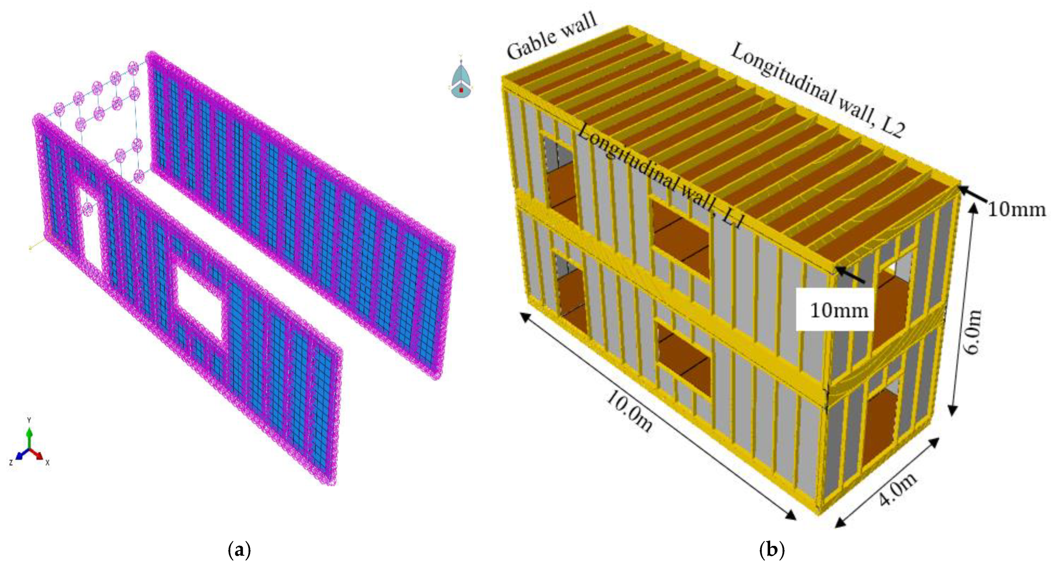
2.1. Geometry

The study utilised structural soft timber from pine tree species (Pinus patula) as timber frames and wood-based boards (particle boards) to form walls and floors. The pine tree for timber production is matured when it reaches 15 to 20 years; otherwise, the mechanical properties can be altered and compromised. For mechanical joints, nail steel fasteners and steel brackets of 5 mm were used to prevent uplift and slip displacements. The timber frame was made from timber rails, beams, and studs to provide stability to the wood-based wallboards. The timber had a bending strength class of 24 MPa (SC24), with sizes of 50 × 100 mm for studs, 50 × 50 mm for rails, and 50 × 150 mm for beams. The height of the studs was 2.5 m, with lengths of longitudinal beams and rails of 10.0 and 9.86 m, respectively. The side or gable beams have a length of 4.0 m. The spacing of floor joists, which is the same as the spacing of studs, was 600 mm. The particle boards had a thickness of 22 mm. The fasteners had different lengths depending on the location. The length of the fastener between the module was 225 mm, between rails/studs/beams and particleboard was 50 mm and between rails, particleboard and rails was 100 mm.

2.2. Material Models

Timber frames have orthotropic characteristics, and therefore, nine properties were required in modelling. These properties include the longitudinal, tangential, and radial modulus of elasticity, as well as Poisson’s ratios in three planes, as listed in Table 1, and the shear moduli, as defined in Equations (1) and (2) [22,23]. The characteristic strength values used in this study are based on Eurocode 5 [13] and Tanzanian standards in Timber. The Poisson’s ratios used were based on the study by O’Ceallaigh et al. [24]. On the other hand, the particleboards and fasteners were modelled as isotropic due to homogeneity in properties in all directions. Therefore, the Poisson’s ratio and elastic modulus of fasteners and steel brackets were 0.3 and 210 GPa, respectively, and the particleboards had a Poisson’s ratio of 0.3 and an elastic modulus of 2700 MPa, respectively. The characteristic properties of timber and boards were used in modelling. This was performed to simulate the exact condition of timber, considering all controlled environmental exposures of timber. This ideal response of timber module under controlled conditions is a representation; however, since the timber in Sao Hill is used all over the country (Tanzania) with diverse environmental conditions, a specific design strength value of timber should be opted in a given country zone where the house is to be built to consider the moisture class in the locality, load class and safety level of building and materials.
E r = E t = E 90 , m e a n × E 0.05 E 0 , m e a n   ;   E 0.05 = E l
G l r ,   G t r ,   G l t = E 0.05 2 ( 1 + ϑ i j )
where E r is the radial modulus of elasticity, E t is the tangential modulus of elasticity, G l r is shear modulus in the longitudinal–radial plane, G t r is the shear modulus in the tangential–radial plane, and G l t is the shear modulus in the longitudinal–tangential plane (all in MPa). ϑ i j is the Poisson’s ratios in the longitudinal–radial, tangential–radial, and longitudinal–tangential planes.

2.3. Element Type, Loading, Interaction and Boundary Conditions

Modelling structures using solid 3D elements in Abaqus increases computational efforts due to the increased number of element nodes and integration points under consideration. Finite beam elements were used to reduce the number of elements in the modelling timber and fasteners, whereas particleboard was modelled as shell elements. The Python scripts were used in Abaqus/Standard to create timber beam elements, fastener beam elements, and particleboard shells, which were then assembled and coupled by the coupling elements. The beam element selected was a 3D element with quadratic interpolation (B32), whereas the shell element was a four-node shell element (S4) with full integration. The mesh sizes used for both elements were 15 and 26 mm for panels and framing, respectively. The spring element was used to couple the endpoints of fasteners and timber frames or wood-based panels, as indicated by the purple dots in Figure 2a. Since the spring element is one-dimensional, six spring elements were used to represent three translational and three rotational degrees of freedom. The stiffness of the coupling spring, i.e., slip modulus, was parametrically varied from 0.0045 N/mm to 948 N/mm (for screwed fastener) to simulate weak and strong mechanical joints between the modules, respectively as in Equations (3) and (4) [13] as in Appendix B. Specifically, the joint between modules was simulated using a less spring stiffness to replicate the friction that occurs when the top timber module is loaded horizontally with only bolts at the module’s corners. For this case, the high spring value represented a strong joint between timber volume modules when screwed fasteners are used in addition to bolts at the corners. Additionally, the angle and uplift steel plates/brackets were modelled between the two timber volume modules and fixed to the top beam of the bottom module. The translational spring was again used in plates to model its resistance when the top module was loaded horizontally. Moreover, the bond between studs and board, rails and boards and between beam and boards was conducted mechanically using the spring stiffness of the fastener (screw) of 948 N/mm. This was to ensure the global rigidity of the module, focusing on slip and global deformation modules for both weak and strong joints.
K s e r = ρ 1.5 d c 23
K u = 2 3 K s e r
In the equations, K s e r is the slip modulus in N/mm, ρ is the density of connecting timber members in kg/m3, d c is the diameter of the fastener in mm, and K u is the slip modulus in ultimate limit states used in modelling, i.e., 948 N/mm.
According to a study by Hammar [1], Sao Hill has an annual mean wind speed of 24 km/h. This wind speed was adopted in this study because it was measured at a height of 10 m, which is higher than the adopted height of two timber modules, 6.0 m, i.e., two floors (G + 1). Therefore, the design load in the region is 1.2 kN, as calculated using the formulas in [7,25], as shown in Appendix A. Eurocode 5 [13] provides a limit for horizontal displacement equivalent to H/300. For the timber module selected in this study, which is 6.0 m high, the maximum horizontal displacement allowed is 20 mm. However, 20 mm could still have detrimental effects on the finishes in the building’s service. An ideal horizontal displacement of 10 mm was adopted and assigned at the top of the second module to reduce the possible damage in service of this type of structure. The spring stiffness of the mechanical joint between the volumes was varied, and reaction forces were probed in the model. The reaction forces above the wind force could indicate a reliable joint, suggesting that the current wind speed in the region is insufficient to produce a displacement of 10 mm. The bottom beams of the bottom module were set fixed to simulate the reinforced concrete strip wall where a timber volume module is typically installed with down bolts. After modelling, the timber, fastener beam elements and shell elements for particleboard were rendered using the dimension profiles initially defined in Abaqus. The rendered typical timber modular building and model development are shown in Figure 2b. The timber modular house consisted of two sets: first, the module with a window and door in one longitudinal wall and doors in the gable walls, and second, the module with an additional door opening in the second longitudinal wall.

3. Results and Discussion
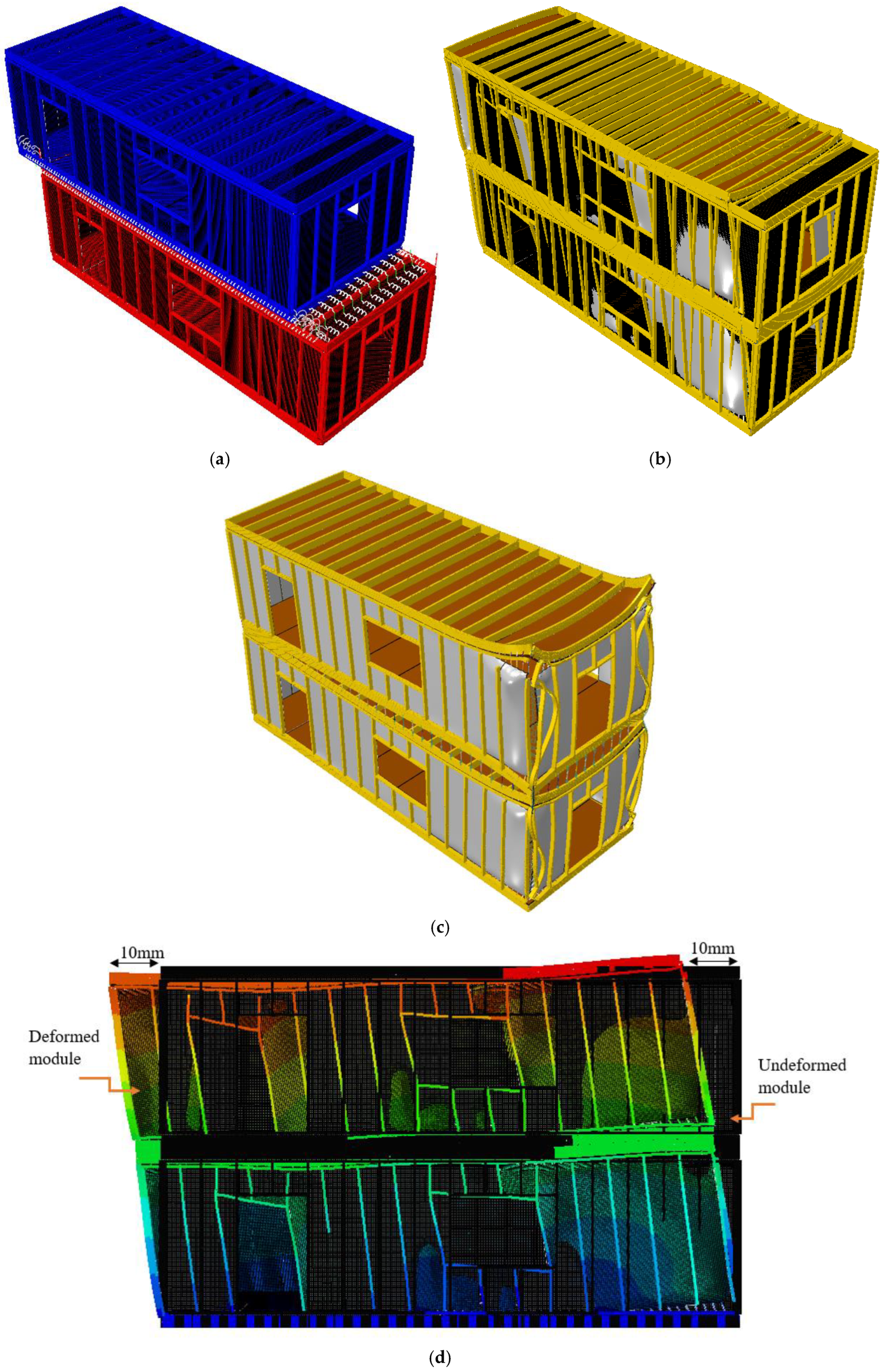
3.1. Failure Modes

Results in Figure 3 show the deformations of two modular timber volumes when subjected to different coupling spring stiffnesses. The deformation of 10 mm was magnified by a factor of 150. The failure mode in Figure 3a simulates the friction behaviour of timber modules with no or weaker corner dowels. The load transfer of the timber modular system is achieved through the corner dowel/bolts and friction resistance between the members [26]. However, due to the top module’s lighter weight, the normal force exerted by the top module on the top beam of the bottom module is small, resulting in weak friction resistance. The weak friction of the lightweight timber structure was represented by a coupling spring stiffness of 0.0045 N/mm. Figure 3b,d show the global response of the two-timber modules for a strong coupling spring stiffness of 948 N/mm. This failure mode aligned with Domínguez et al. [19], such that the screwed fastener resists the rope effect due to embedded threads in timber members resulting in less slip displacement. This limited slip displacement between volume modules resulted in the global deformation of members demanding the use of screw fasteners for all other members in the modules. The model in Figure 3c represents the uplift deformation of timber modules. The results show that in the absence of fasteners between modules (weak friction), uplift deformation can occur despite the steel plates being in the corners of the modules, thereby increasing the chances of horizontal displacement. The results align with those of Kuai et al. [14] regarding the potential contribution of uplift to the overall horizontal displacement.

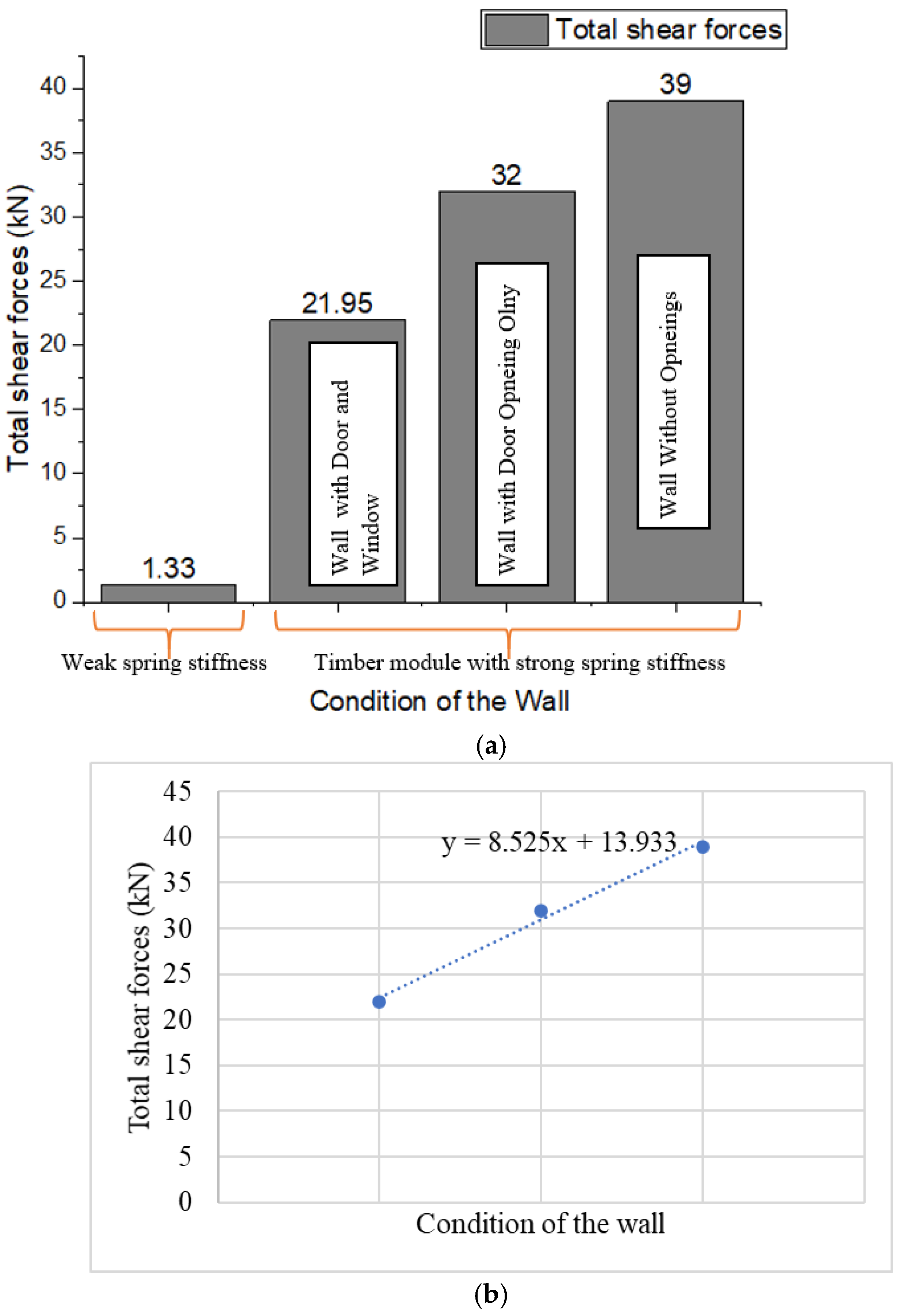
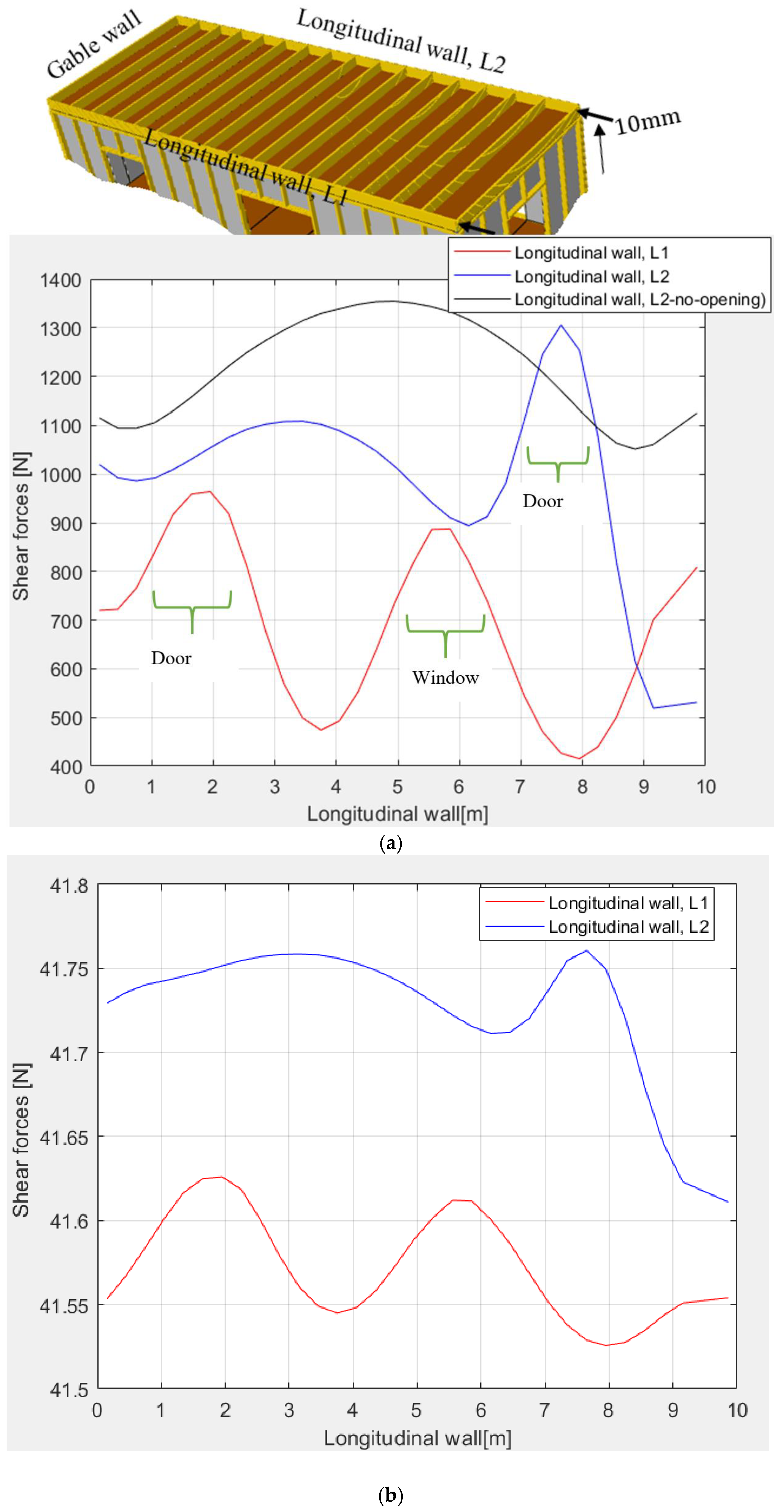
3.2. Influence of Opening on Shear Carrying Capacity of Timber Modular

The results in Figure 4 and Figure 5 represent the total shear forces in the longitudinal walls and the shear forces transferred along the longitudinal wall joint between timber volume modules with and without openings, respectively. The shear forces under consideration are forces along the timber fibers of the bottom beam of the bottom module. The results show that the shear forces for both weak and strong joints are high in the opening zones. These results align with those of Casagrande et al. [27], which revealed that when horizontal forces are applied, the stresses are concentrated at the opening corners. Despite this, the trend was expected to have only high stress at the corners; however, the results show the stresses tend to increase from the door corner, 910 N to 960 N at the middle of the door for strong joints. This trend was also observed for models with less spring stiffness. This increase in shear resistance is the result of a shorter opening span and the absence of bottom stud members to redistribute stresses. In contrast to the door opening, the studs below the window redistribute stresses, resulting in less shear stress compared to that of the door opening. Generally, the opening affected the shear performance of timber volume modules when the stiffness of the mechanical joint increased. For instance, in Figure 4a and Figure 5b, a model with less stiffness has the same total shear force transferred in the longitudinal walls, which is 1.33 kN. This was due to less resistance as the module slipped, resulting in no influence on openings. However, when stiffness increases, the longitudinal wall, L1, with a door and window, transfers a total shear force of 21.95 kN, which is 44% less than the shear transfer for a solid wall, i.e., a wall without openings. Furthermore, when a door opening in the longitudinal wall, L2, was introduced, the stress transfer mechanism was the same as that of the wall, L1, at the opening (see Figure 5a). Introducing door openings in the wall, L2 reduced the shear force to 32 kN, which is 17.9% less than the model of solid walls (39 kN). The regression model indicates that joints with strong spring stiffness can resist shear forces up to 13.9 kN for the modules with door and window openings in both longitudinal walls.
Despite the stress concentration at the door opening, a wider window opening contributes to a 26.1% stress reduction. These results contrast with the findings in [28,29], which suggest that a window opening with a larger horizontal dimension and a smaller vertical dimension has higher shear resistance compared to an opening with a smaller horizontal dimension and a longer vertical dimension. The results in the current study used windows with large areas compared to the door opening. In addition, the shear transfer in a module timber building depends on the number of terminated stud timber members and the location of the opening relative to the load application [30]. The opening close to the point of load application results in less shear force being transferred compared to the opening located at the far end. This justifies the high shear reduction to the window opening in the wall, L1 (close to the point of load application), if compared with the door opening located at the far end of the wall. The results of the current study suggest that the use of diagonal timber members between the corners of openings is necessary to de-concentrate stress and enhance the structural integrity of timber structures. Despite the strong spring stiffness, strength and modulus properties of the joining timber members are important as they also govern the overall global performance of the resulting timber structure [31].

4. Conclusions and Recommendations

The study examined the structural response of timber modular houses with openings on wind loads, considering lateral and uplift displacements. The study has drawn the following conclusions and recommendations.
  • The prescribed displacement of 10 mm resulted in a total shear force greater than the wind load, indicating that a wind speed of 24 km/h can produce a displacement of less than 10 mm during the building’s service life. This gives a promising adaptation of these buildings with minimal deformation of service utilities.
  • The screwed fasteners with a slip modulus of 948 N/mm can yield a total shear resistance of 21.5 kN for timber modules with door and window openings in a single wall. This signifies a reliable mechanical joint when the screw fasteners are used.
  • The shear stress is concentrated at the corners of the opening; however, the peak stress is observed at the door opening since the bottom of the door has no stud to redistribute stresses.
Despite strong and reliable joints developed between modules, the opening effect seems to influence the overall global shear transfer between modules. It is, therefore, recommended to use crossing-diagonal timber members between the corners of openings to facilitate the possible redistribution of shear when the wind blows in alternative directions. Since a wind speed of 24 km/h in Sao Hill can result in a small displacement of less than 10 mm, these sustainable houses can be adopted because the degree of damage to service utilities is within the tolerable scale. These houses could help limit the overexploitation of natural resources, such as aggregates, for the benefit of future generations in Tanzania.

Funding

This research received no external funding.

Data Availability Statement

The data that support the findings of this study are available from the corresponding author upon reasonable request.

Conflicts of Interest

The author declares no conflict of interest.

Appendix A

Wind Load Calculation
Height of two timber volume modules6 m
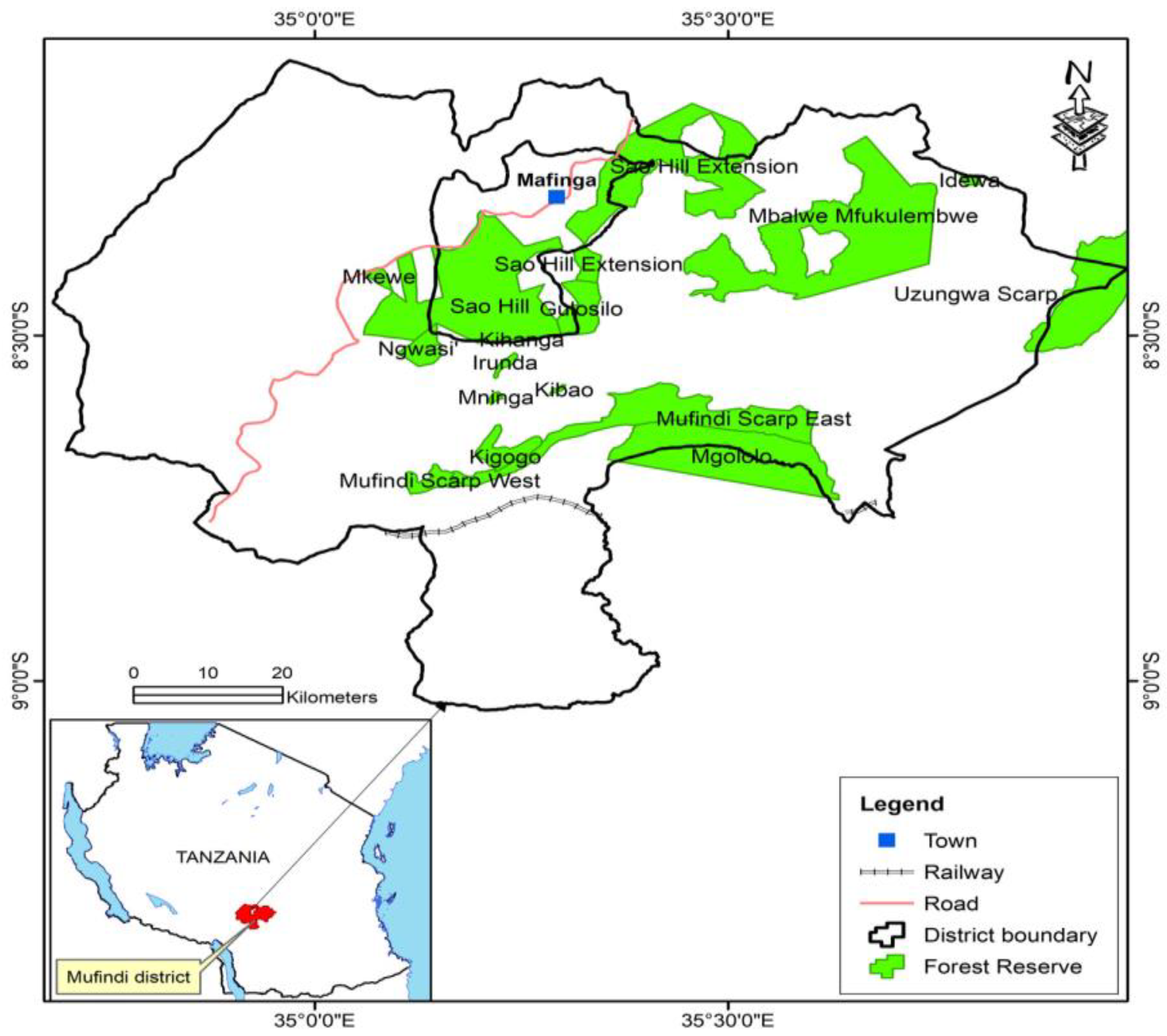
Sao Hill is covered with vegetation and permanent vegetation, classified as terrain type III
The average annual wind speed of Sao Hill,6.6 m/s
Using Tanzania’s national Annex as in BRU,
The characteristic/peak velocity pressure q p = 0.63 v b 2       N m 2 27.4428N/m2
Width of timber structure 4 m
Height-to-width ratio of the structure 1.5
The shape factor for external pressure that
depends on the building shape, C e , 10 1.2
Wind pressure, W e = q p C e , 10 32.9314N/m2
The point load on top of the gable wall of the structure790.353N
The design load 1185.53N

Appendix B

  • Spring stiffnesses
  • Case 1: Strong Spring Stiffness between Modules
  • Degree of Freedom (DoF) No. 1: 948 N/mm
  • Degree of Freedom (DoF) No. 2: 948 N/mm
  • Degree of Freedom (DoF) No. 3: 948 N/mm
  • Degree of Freedom (DoF) No. 4: 948 N/rad
  • Degree of Freedom (DoF) No. 5: 948 N/rad
  • Degree of Freedom (DoF) No. 6: 948 N/rad
  • Case 2: Weak Spring Stiffness between Modules
  • Degree of Freedom (DoF) No. 1: 0.0045 N/mm
  • Degree of Freedom (DoF) No. 2: 0.0045 N/mm
  • Degree of Freedom (DoF) No. 3: 0.0045 N/mm
  • Degree of Freedom (DoF) No. 4: 0.0045 N/rad
  • Degree of Freedom (DoF) No. 5: 0.0045 N/rad
  • Degree of Freedom (DoF) No. 6: 0.0045 N/rad
  • Note: DoF No. 1, 2 and 3 are translational degrees of freedom, and DoF No. 4, 5 and 6 are rotational degrees of freedom.

References

  1. Hammar, L. Distribution of Wind and Solar Energy Resources in Tanzania and Mozambique. 2011. Available online: https://www.researchgate.net/publication/267960027 (accessed on 22 December 2024).
  2. Theodory, T.F. Framing the forests future: A transition to green growth among the forests dependent communities in Mafinga Town Council, Tanzania. Afr. J. Econ. Sustain. Dev. 2022, 9, 68–85. [Google Scholar] [CrossRef]
  3. Mahongo, S.B.; Francis, J.; Osima, S.E. Wind Patterns of Coastal Tanzania: Their Variability and Trends. West. Indian Ocean. J. Mar. Sci. 2011, 10, 107–120. [Google Scholar]
  4. Cui, H.; An, H.; Ma, M.; Han, Z.; Saha, S.C.; Liu, Q. Experimental Study on Wind Load and Wind-Induced Interference Effect of Three High-Rise Buildings. J. Appl. Fluid Mech. 2023, 16, 2101–2114. [Google Scholar] [CrossRef]
  5. Mironova, J. Wind impact on low-rise buildings when placing high-rises into the existing development. In IOP Conference Series: Materials Science and Engineering; Institute of Physics: Bristol, UK, 2020. [Google Scholar] [CrossRef]
  6. Njau, E.C. Velocity Characteristics of Wind Patterns in Tanzania. Renew. Energy 1997, 11, 37–46. [Google Scholar] [CrossRef]
  7. Haavaldsen, T. Loads for Structural Design. In BRU Technical Guideline No.2 Ministry of Land; Housing and Urban Development: Dra es Salaam, Tanzania, 1981. [Google Scholar]
  8. Ishida, Y.; Yoshida, A.; Yamane, Y.; Mochida, A. Impact of a single high-rise building on the wind pressure acting on the surrounding low-rise buildings. J. Wind. Eng. Ind. Aerodyn. 2024, 250, 105742. [Google Scholar] [CrossRef]
  9. Škvorc, P.; Kozmar, H. The effect of wind characteristics on tall buildings with porous double-skin façades. J. Build. Eng. 2023, 69, 106135. [Google Scholar] [CrossRef]
  10. Ussher, E.; Aloisio, A.; Rathy, S. Effect of lateral resisting systems on the wind-induced serviceability response of tall timber buildings. Case Stud. Constr. Mater. 2023, 19, e02540. [Google Scholar] [CrossRef]
  11. Ormarsson, S.; Johansson, M. Finite element simulation of global structural behaviour of multifamily timber buildings using prefabricated volume modules. In Proceedings of the World Conference on Timber Engineering, Seoul, Republic of Korea, 20–23 August 2018. [Google Scholar]
  12. Li, J.; Andersen, L.V.; Hudert, M.M. The Potential Contribution of Modular Volumetric Timber Buildings to Circular Construction: A State-of-the-Art Review Based on Literature and 60 Case Studies. Sustainability 2023, 15, 16203. [Google Scholar] [CrossRef]
  13. EN 1995-1-1; Eurocode 5: Design of Timber Structures—Part 1-1: General—Common Rules and Rules for Buildings. European Committee for Standardization: Brussels, Belgium, 2004.
  14. Kuai, L.; Ormarsson, S.; Vessby, J. Numerical and experimental investigations of prefabricated light-frame timber modules. Eng. Struct. 2024, 303, 117528. [Google Scholar] [CrossRef]
  15. Maharjan, R.; Kuai, L.; Vessby, J.; Ormarsson, S. An experimental analysis of full scale light-frame timber modules. Eng. Struct. 2024, 304, 117617. [Google Scholar] [CrossRef]
  16. Vessby, J.; Serrano, E.; Olsson, A. Coupled and uncoupled nonlinear elastic finite element models for monotonically loaded sheathing-to-framing joints in timber based shear walls. Eng. Struct. 2010, 32, 3433–3442. [Google Scholar] [CrossRef]
  17. Meghlat, E.M.; Oudjene, M.; Ait-Aider, H.; Batoz, J.L. A new approach to model nailed and screwed timber joints using the finite element method. Constr. Build. Mater. 2013, 41, 263–269. [Google Scholar] [CrossRef]
  18. Lidelöw, H.; Kliger, R.; Johansson, M.; Mårtensson, A.; Crocetti, R.; Norlin, B. Design of Timber Structures Volume 1, Structural Aspects of Timber Construction. 2015. Available online: https://www.swedishwood.com (accessed on 20 January 2025).
  19. Domínguez, M.; Fueyo, J.G.; Cabezas, J.A. Accounting of the thread embedment in timber structures dowel-type joints. Load-slip relationship. Proc. Inst. Mech. Eng. C J. Mech. Eng. Sci. 2017, 231, 150–160. [Google Scholar] [CrossRef]
  20. Tenório, M.; Ferreira, R.; Belafonte, V.; Sousa, F.; Meireis, C.; Fontes, M.; Vale, I.; Gomes, A.; Alves, R.; Silva, S.M.; et al. Contemporary Strategies for the Structural Design of Multi-Story Modular Timber Buildings: A Comprehensive Review. Appl. Sci. 2024, 14, 3194. [Google Scholar] [CrossRef]
  21. Al-Najjar, A.; Dodoo, A. Modular multi-storey construction with cross-laminated timber: Life cycle environmental implications. Wood Mater. Sci. Eng. 2023, 18, 525–539. [Google Scholar] [CrossRef]
  22. Borgström, E.; Karlsson, R.; Thelander, I.C.; Martinac, V. Design of Timber Structures Rules and Formulas According to Eurocode 5 Volume 2 EDITION 2:2016 Editor Eric Borgström Facts Reviewer Design and Production ProService Kommunikation AB. Available online: https://www.swedishwood.com (accessed on 4 February 2025).
  23. Ottosen, N.S.; Petersson, H. Introduction to the Finite Element Method; Pearson: London, UK, 1992. [Google Scholar]
  24. O’Ceallaigh, C.; Conway, M.; Mehra, S.; Harte, A.M. Numerical Investigation of Reinforcement of Timber Elements in Compression Perpendicular to the Grain using Densified Wood Dowels. Constr. Build. Mater. 2021, 288, 122990. [Google Scholar] [CrossRef]
  25. EN 1991-1-4; Eurocode 1: Actions on Structures—Part 1–4: General Actions—Wind Actions. Committee for Standardization: Brussels, Belgium, 2010.
  26. Malo, K.A.; Abrahamsen, R.B.; Bjertnæs, M.A. Some structural design issues of the 14-storey timber framed building ‘Treet’ in Norway. Eur. J. Wood Wood Prod. 2016, 74, 407–424. [Google Scholar] [CrossRef]
  27. Casagrande, D.; Fanti, R.; Greco, M.; Gavric, I.; Polastri, A. On the distribution of internal forces in single-storey CLT symmetric shear-walls with openings. Structures 2021, 33, 4718–4742. [Google Scholar] [CrossRef]
  28. Aljuhmani, A.G.; Alwashali, H.; Ogasawara, A.; Atsuzawa, E.; Maeda, M.; Seki, M. Experimental Investigation on the Effect of Openings on the In-plane Shear Strength and Stiffness of Cross-laminated Timber Panels. Eng. Struct. 2022, 254, 113786. [Google Scholar] [CrossRef]
  29. Szczepanski, M.; Manguri, A.; Saeed, N.; Chuchala, D. The Effect of Openings’ Size and Location on Selected Dynamical Properties of Typical Wood Frame Walls. Polymers 2022, 14, 497. [Google Scholar] [CrossRef]
  30. Kuai, L.; Ormarsson, S.; Vessby, J.; Maharjan, R. A numerical and experimental investigation of non-linear deformation behaviours in light-frame timber walls. Eng Struct 2022, 252, 113599. [Google Scholar] [CrossRef]
  31. Vassiliou, V.; Barboutis, I.; Kamperidou, V. Strength of Corner and Middle Joints of Upholstered Furniture Frames Constructed with Black Locust and Beechwood. Wood Res. 2016, 61, 495–504. [Google Scholar]
Figure 1. Sao Hill Plantation Forest Reserves [2].
Buildings 15 01459 g001
Figure 2. Timber volume module; (a) model development and spring coupling; and (b) rendered timber volume modules.
Buildings 15 01459 g002
Figure 3. Failure modes of timber volume modules: (a) Horizontal displacement for spring stiffness of 0.0045 N/mm, (b,d) Global deformation with high spring stiffness of 948 N/mm and (c) Uplift deformation for spring stiffness of 948 N/mm.
Buildings 15 01459 g003
Figure 4. Total shear forces in the longitudinal walls with and without opening; (a) comparison between weak and strong spring stiffness and (b) regression model on strong spring stiffness.
Buildings 15 01459 g004
Figure 5. Shear transfer along the longitudinal wall joint between timber volume modules with and without opening (a) Spring stiffness of 948 N/mm and (b) 0.0045 N/mm.
Buildings 15 01459 g005
Table 1. Physical and Mechanical Properties of Timber Frames [13,22,24].
Material PropertyValue
Mean modulus of elasticity parallel to the grain, E 0 , m e a n (MPa)11,000
Characteristic compressive strength parallel to the grain, f c , 0 (MPa)21
Characteristic compressive strength perpendicular to the grain, f c , 90 (MPa)2.5
Characteristic tensile strength parallel to the grain, f t , 0 (MPa)14.5
Characteristic tensile strength perpendicular to the grain, f t , 90 (MPa)0.4
Characteristic modulus of elasticity parallel to the grain, E 0.05 , E l (MPa)7400
Characteristic bending strength perpendicular to the grain, f m (MPa)24
Mean modulus of elasticity perpendicular to the grain, E 90 , m e a n (MPa)370
Characteristic density of timber, ρ (kg/m3)350
Poisson’s ratios ϑ l r , ϑ t r , ϑ l t 0.48, 0.56, 0.3
Diameter of the fastener, d c (mm)5
Radial, tangential modulus of elasticity, E r ,   E t (MPa)248.9
Shear modulus, G l r ,   G t r ,   G l t (MPa)2500, 2372, 2846
Disclaimer/Publisher’s Note: The statements, opinions and data contained in all publications are solely those of the individual author(s) and contributor(s) and not of MDPI and/or the editor(s). MDPI and/or the editor(s) disclaim responsibility for any injury to people or property resulting from any ideas, methods, instructions or products referred to in the content.

