1. Introduction
Building façades are highly vulnerable to wind and windborne debris during hurricanes and tornados. Damage to the façade often results in a catastrophic breach of the building envelope, resulting in costly damage to the interior. Laminated glazing has been widely used in architectural applications, not only because of its impact resistance, but also because it maintains the integrity of the building envelope by holding the broken glass shards in place via a layer of polyvinyl butyral (PVB) thus minimizing injury to people and damage to property.
Several researchers have worked on the impact of wind and debris acting separately on the glazing. Flocker and Dharani [
1,
2,
3,
4] simulated low velocity, small missile impact on laminated architectural glazing (LAG) and presented the effects of different PVB properties and glazing geometries to find the optimum LAG configuration. Behr
et al. [
5] measured the dynamic strains in LAG due to simulated debris impact and compared them with those predicted by Flocker and Dharani [
1]. Vallabhan and Chao [
6] studied the stresses and displacements developed in window glass systems of different aspect ratios subjected to static wind load. An iterative procedure was developed which incorporated non-dimensional curves relating central deflections, maximum principal stresses and lateral design wind pressures. Duser
et al. [
7] conducted a stress analysis and failure probability analysis of laminated glazing subjected to uniform lateral pressure. Dharani
et al. [
8] developed an analytical model to predict the cumulative probability of damage to the inner glass ply due to small missile impact. The outer ply was modeled as a sacrificial ply and a subroutine was incorporated in the finite element to predict Hertzian cone crack failure. Ji
et al. [
9] studied the probability of damage to the outer ply due to steel ball impact in LAG systems. The damage probability was found using a finite element model in combination with a statistical failure prediction model, and found that damage was independent of glass ply thickness and PVB thickness. Kaiser
et al. [
10] conducted a series of experiments using sacrificial ply design for LAG to find the probability of damage to the inner ply due to 2 gram steel ball impact. In sacrificial ply designs, the outer ply is allowed to break. Their study revealed that the thicknesses of both the inner glass ply and PVB have a bearing on the impact resistance of the inner glass ply, but the thickness of the outer ply had less effect. Tsai and Stewart [
11] studied the stress and deflection characteristics of large plates undergoing large defections due to wind load through series of experimental tests and finite element simulations on glass plates of various geometric configurations. Saxe
et al. [
12] performed a series of steel ball impact tests on LAG to study impact resistance. The impactor size, inner and outer glazing thicknesses as well as type of inner glass ply were varied.
Researchers have used the Continuum Damage Mechanics (CDM) principle to predict the damage pattern and zone size due to impact on glazing. CDM, first introduced by Kachanov [
13], is a continuous measure of the state of internal stiffness degradation of a material. It describes the coupling effect of material damage and stress-strain. Damage is taken into account by introducing the damage variables into the constitutive Equations of the continuum. This model describes the damage in an average sense instead of describing the fine details of micro-defect and macro-crack patterns. Sun and Khaleel [
14] developed an anisotropic elastic damage model with a linear damage evolution law to study the static indentation damage in soda lime glass. The damage pattern and zone size were predicted for both loading and unloading cycles and agreed well with experimental results. Sun
et al. [
15] used this model to study the damage due to stone impact on automotive windshields for different windshield curvatures and thickness. More recently Zhao
et al. [
16,
17] used the model to study the damage in windshields due to head impact [
16], and subsequently, the damage due to blast loads [
17] on architectural glazing.
The bulk of the published work on this topic either deals with the stress and dynamic analyses of undamaged LAG or the total failure of LAG. Both deterministic and probabilistic approaches have been used to predict LAG failure. The pre-failure damage response of LAG due to the combination of wind loading and windborne debris impact has not been studied so far and hence the motivation for this study. The principal objective of the current study is to predict the damage in glass plies of a circular laminated architectural glazing under the combined loading of wind and debris impact, and to determine the relationship between the damage and the salient LAG material and geometric parameters.
2. Continuum Damage Mechanics (CDM) Model
The CDM model developed for soda-lime glass by Sun and Khaleel [
14] is adopted here. The authors understand that there are several types of damage models that can be applied to the problem studied in this paper. The model by Sun and Khaleel [
14] is used because this approach has been used in the study of laminated automotive glazing and the authors have had some success in applying it to a LAG subjected to blast loading. It is an anisotropic elastic model with a linear damage evolution law used to model the damage due to cracking of laminated glass. A damage tensor
Dij that models the material nonlinearity due to the deformation process is introduced in to the constitutive Equation [
14]. The constitutive relationship of the material is thus expressed as:
where the stiffness matrix is divided into two parts with
![Buildings 03 00422 i015]()
representing the matrix of undamaged material and
![Buildings 03 00422 i016]()
representing the added influence of damage. The matrix components [
14] are given as:
and
where λ and μ are the Lame constants for glass and can be written in terms of Young’s modulus, E and Poisson’s ratio,
ν, as:
Damage parameters C
1 and C
2 are defined such that the axial stress vanishes as the damage component D
11 approaches 1.0 in a uniaxial tension test [
18,
19]. This condition leads to the following relationship:
The damage tensor defined above represents the two modes of damage defined in fracture mechanics. One is due to the principal normal stress resulting in the opening mode of failure (mode I) and the other due to maximum shear stress components (mode II). The damage tensors for mode I and mode II are given by Equations (6) and (7), respectively [
14].
For the small missile case, such as a small stone impacting on the windshield of an automobile, Sun
et al. [
15] used σ
crit = 372 MPa and σ
threshold = 23 MPa for the critical and the threshold stresses, respectively. Data is not readily available for large missile impact. Bouzid
et al. [
20] showed that the critical stress to failure is proportional to the time to failure. The time span involved in the case of large missile impact is on the order of milliseconds while it is on the order of microseconds [
21,
22] for the small case. Hence it is conceivable that the critical stress for the large missile case would be considerably lower in magnitude than that of the small missile case. For the sake of analysis and computation, a conservative value of 100 MPa, which is the static tensile strength of a soda lime glass, is used for the critical stress (σ
crit = 100 MPa). Initially, the material was assumed to be defect free with a damage tensor value of 0.0 (virgin state), and with the values increasing to 1.0 representing a fully damaged state. For this study, instead of just searching for the fully damaged state, results will be presented for a range of damage states because the actual value of the damage at failure is highly dependent on several factors. This issue is further elaborated in section 4 just before presenting the results for various cases. The cracking and damage process being irreversible, the component damage tensor for a material point at the
nth time increment as determined by Sun and Khaleel [
14], may be written:
where
n and
n−1 represent the
nth and (
n−1)
th time increment of the analysis.
3. Impact Problem Description
Windborne debris, as per ASCE building codes [
23], has been classified into two categories based on their mass and elastic modulus properties with respect to those of glass. One is the small hard missile, which represents roof gravel and the other the large soft missile that represents timber from buildings and trees. Small missile impact is of concern at typical building elevation (<30 ft. [9.1 m]) whereas large missile impact is more important at greater (>30 ft. [9.1 m]) elevations. As per ASTM standard E1886 [
24], a 2 gram (0.004 lb.) steel ball is chosen to be representative of small missiles with an impact velocity of 39.62m/s. From ASTM standard E1996 [
25], three large missile types are recommended. The missile configuration is as specified in
Table 1. The wind load calculated for small and large missile impact is based on the maximum wind speed and the type of area or surroundings. A wind speed of around 130 mph (58 m/s) is considered, and the area is assumed to be dotted with public utility facilities. In the case of a large missile with rectangular cross section, the problem has to be analyzed for different orientations with respect to the plane of the glass. To simplify the analysis and make the problem computationally tractable, a circular large missile cross section is chosen to make it symmetrical (axisymmetric) about the long axis of the missile. Large missiles having both flat and round impacting ends are studied. For the same reasons, a 2-D axisymmetric model (circular panel) is used to model the panel even though most architectural LAG applications use rectangular panels. Using appropriate plate Equations [
26], deflections for the circular and square panels were done for two loading cases, point force at the center and a uniformly distributed pressure on the top surface of the panels. The difference in the maximum central deflections between the circular plate and the square plate, subjected to either uniform pressure or a point-force, is found to be relatively small.
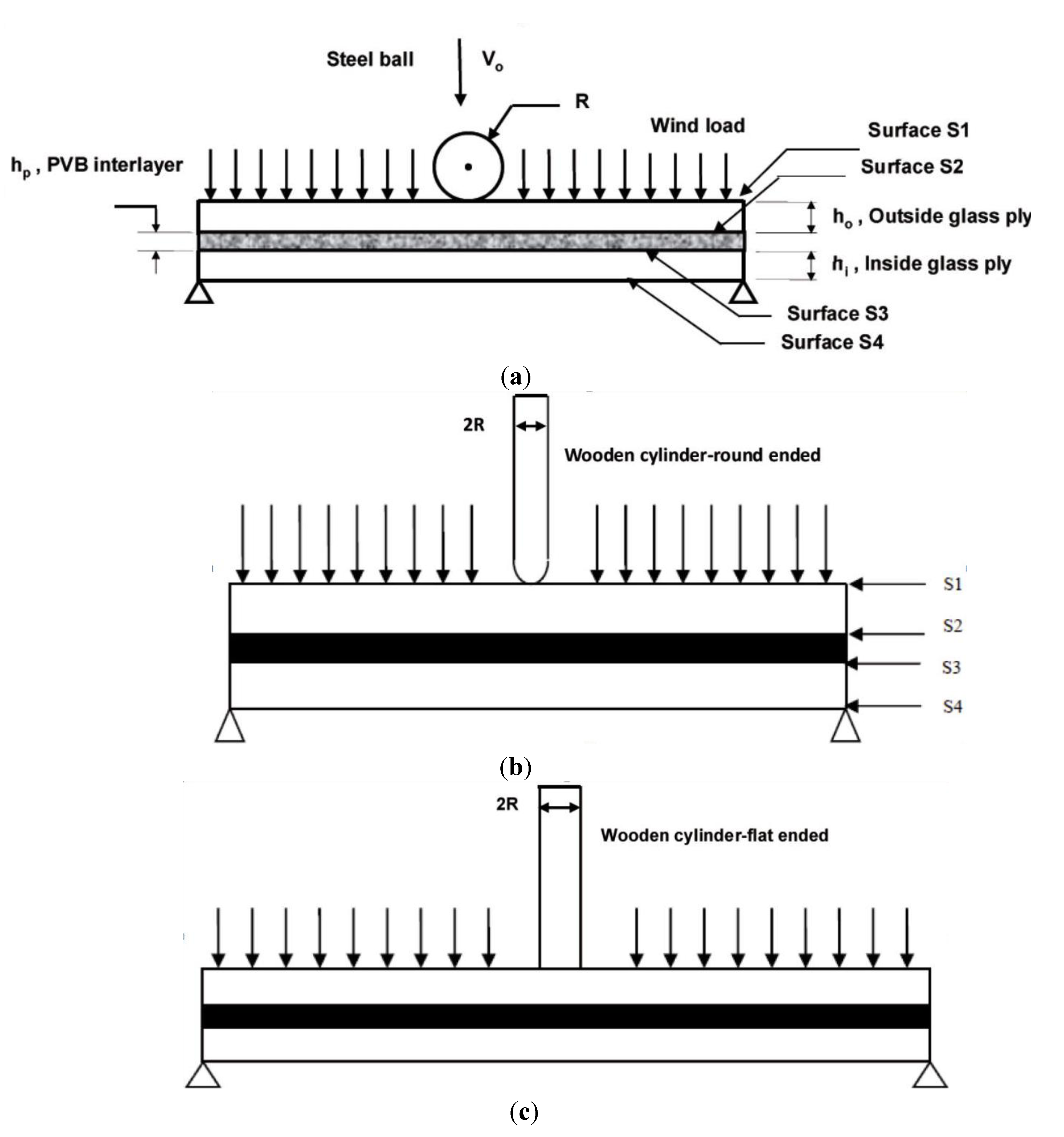
A schematic representing the three missile types and the two dimensional (2-D) model geometry of the circular LAG panels is shown in
Figure 1. The missile impact is assumed to occur normal to the plane of the panel at a velocity
Vo. The laminated plate is comprised of two soda lime glass sheets sandwiching a PVB interlayer. The thicknesses of the outer and inner glass plies and the PVB interlayer are
ho, hi and
hp, respectively. The panel is simply supported on the circumferential edge. The wind load is modeled as a uniform static load (pressure). Ghrib and Tinawi [
27], in their study of seismic analysis of concrete gravity dams, first analyzed the response of dam due to its self-weight and hydrostatic pressure of the reservoir on the upstream wall prior to earthquake excitation. A similar method is adopted here. The loading is done sequentially with static wind load followed by the debris impact load rather than superposing the two simultaneously. The interlayer bond is assumed to be perfect with no de-bonding or slipping during impact.
Table 1.
Baseline data.
| Materials and variables | Parameters and properties |
|---|
| Glass | E = 72 GPa, ρ = 2500 kg/m3, ν = 0.25 |
| PVB | Go = 1 GPa, G∞ = 0.69 MPa, ρ = 1100 kg/m3, β = 12.6 s−1, E = 2.5714 GPa, ν = 0.2857 |
| Steel ball [2 g] | E = 200 GPa, ν = 0.29, ρ = 7800 kg/m3 |
| Wooden cylinder [2050 g] (Douglas Fir) | Er = 1 GPa, Eθ = 737 MPa, Ez = 14.74 GPa, νrθ = 0.39, νθz = 0.036, νzr=0.029, Grθ = 103.2 MPa, Gθz = 943.4 MPa, Gzr = 1.15 Gpa |
| Impact velocity | Steel ball: 39.6 m/s; Wooden cylinder: 24.4 m/s |
| Plate dimensions | Panel area: Radius = 0.74 m |
| - | Inner ply thickness,
hi = 4.76 mm |
| - | Outer ply thickness,
ho = 4.76 mm |
| - | PVB interlayer thickness,
hp = 1.52 mm |
| Missile dimensions | Steel ball:
R = 3.96875 mm |
| - | Wooden cylinder:
R = 32.81 mm; length = 2.4 m |
Figure 1.
Schematic of different missile types impacting on 2-D laminated glazing. (a) Small missile; (b) Large missile with round impacting end; (c) Large missile with flat impacting end.
Figure 1.
Schematic of different missile types impacting on 2-D laminated glazing. (a) Small missile; (b) Large missile with round impacting end; (c) Large missile with flat impacting end.
3.1. Material Models
In general, the stress tensor for the impact problem is computed as the sum of deviatoric and volumetric components
where σ
ij is the stress tensor; S
ij is the deviatoric stress tensor;
p = −σ
kk /3 is the pressure; and δ
ij is the Kronecker delta.
The glass plies and small missile (steel ball) are modeled as isotropic, linear elastic, whereas the large missile (wooden cylinder) is modeled as orthotropic and linear elastic to incorporate the directional properties of the wood. The deviatoric behavior is given by
while the volumetric behavior is given by
where,
E is Young’s modulu;
εij is the strain tensor;
ν is the Poisson’s ratio and
εij=
εkk is the volumetric strain. In several earlier studies on LAG, the PVB interlayer has been traditionally modeled as linear-viscoelastic [
1,
2,
3,
4]. The most recent work on laminated glazing by Wei and Dharani [
28] has shown that PVB can be modeled as linear elastic by using the short term shear modulus for a transient response,
Go, and bulk modulus, K, to give the elastic constants
where,
Ep is PVB Young’s modulus and
νp is PVB Poisson’s ratio. In the present work, PVB is modeled as linear elastic. Further, it is assumed that the interface between the interlayer and the glass plies is perfect with no debonding. If the debonding between the PVB interlayer and the adjoining glass plies occurs it typically initiates where the cone crack in the glass ply meets PVB interface at which point stresses are high [
3]. The objective of the current study is to identify locations where micro-damage in glass initiates. The propagation of such damage or the formation of a cone crack in glass ply is not a part of this study and hence the issue of PVB debonding is not of interest. The PVB interlayer debonding has been modeled and studied by Flocker and Dharani [
4].
3.2. Design Wind Pressure
The ASCE standards [
23] provide three methods to calculate the design loads, a simplified procedure, an analytical procedure, and a wind tunnel procedure. In the simplified procedure, which does not require the complicated computations necessary in the analytical procedure, the parameters given in standard tables are used. The simplified procedure is applicable for low-rise buildings only. The analytical procedure is only applicable for buildings of regular shape. The wind tunnel procedure is recommended for buildings of unusual shape which warrant more accurate testing for wind loads. In this study the analytical procedure is used to find the design wind load (pressure) as given by [
23]
where,
q is the pressure at height above the ground;
G is the gust factor;
Cp is the pressure coefficient. The term
q G Cp in the above Equation refers to external wind pressure acting on the glazing. The term
qiG Cpi refers to pressure inside the building and is taken to be zero. The gust effect factor accounts for the loading effects in the wind direction due to wind interaction with the structure. The basic velocity pressure,
q, is given by
where
Kz,
V, and
I denote the velocity pressure coefficient, wind velocity, and importance factor, respectively. The importance factor accounts for the degree of hazard to human life and damage to property. The pressure coefficient denotes the actual loading on each surface of the building as a function of wind direction.
3.3. Computational Model
To simplify the analysis and make the problem computationally tractable, the wind and debris impact on laminated glass is modeled as a 2-D axisymmetric (pseudo 3-D) problem in which a circular plate with radius of 0.74 m was modeled instead of the actual rectangular plate. 2-D axisymmetric boundary conditions were applied to the layers and the impactor along the axis of symmetry. The static analysis is initially done using ABAQUS STANDARD [
29] to model the static wind load. The IMPORT option is used to transfer the stresses and displacements at the end of static analysis to the dynamic analysis step in which the wind-borne debris impact is simulated. The dynamic problem is studied numerically using the finite element code ABAQUS EXPLICIT [
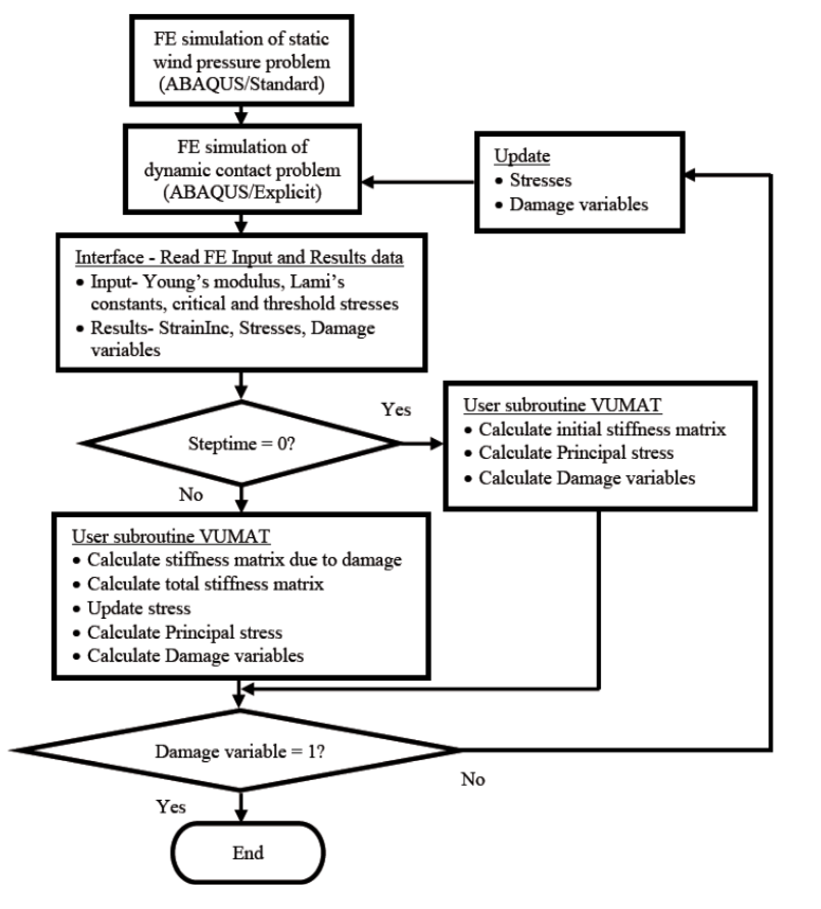
29] with automatic time incrementation. Surface-to-surface contact pair algorithm in ABAQUS EXPLICIT was used to model contact between the missile and glass panel to prevent penetration. The bias option in the pre-processor, ABAQUS-CAE, was used to generate fine mesh for the impactor and the glazing. In the glass panel, the biasing is applied in two dimensions, such that along the length of panel, the mesh becomes progressively finer as we move from the side of the panel towards the center of panel (impact site) and along the depth (thickness) of the panel, the mesh grows finer as we move from the surface in contact to the PVB to the free surface of the glazing (inner and outer). The impactor is similarly meshed using the bias option such that the region of contact area is finely meshed. A mesh convergence study is implemented resulting in finer mesh in the vicinity of impact to better capture the impact response. Four-node bilinear axisymmetric elements (CAX4R) are used. The optimized mesh for the entire LAG model has 60384 elements in total. Contact between the layers is set as tied for the perfect bonding assumption. The CDM model is developed as a Fortran user subroutine (VUMAT) and interfaced with the ABAQUS code to simulate the constitutive behavior of the glass. The computational process is outlined in a flow chart shown in
Figure 2.
Figure 2.
Flow-chart of the computational process.
Figure 2.
Flow-chart of the computational process.
4. Results and Discussion
The main objective of this study is to examine analytically the damage behavior of a circular laminated architectural glazing under combined loading of debris impact and wind pressure. In particular, determine the role of various material and geometric parameters on the damage pattern and sizes. The baseline data used in this study is listed in
Table 1. Experimental work to validate the model predictions has not been done as part of this investigation. Most of the published work on experimental studies deals with either pre-failure or total failure of LAG. Distributed damage modeled here serves as precursor to final failure. The results of this work may be used as a guide in planning some selective experimental work, in the future, to characterize pre-failure damage initiation and distribution.
The labeling of different surfaces of the LAG is shown in
Figure 1. These surfaces will be referred to throughout this section to explain the damage on it. Surface 1 (S1) represents the outside impact surface and surface 4 (S4) represents the inside non-impact surface. There are three primary mechanisms of damage. The cracking mechanisms and the corresponding stresses are shown in
Figure 3. Web-shaped damage (D
11) is caused by the radial stress (σ
1) when it exceeds the corresponding critical value thereby resulting in a circumferential crack (or web-shaped crack). Star-shaped cracks (D
33) are caused by the circumferential tensile stress (σ
3) when it exceeds the corresponding critical value, thereby, leading to a radial (or star-shaped) crack. These are the two most commonly observed damage modes in typical glass damage under impact loading. Shear damage is caused by shear stress (σ
12) under a confining compressive stress state. Knight
et al. [
30] have shown that a plastic deformation occurs below the impactor when shear stress exceeds the yield stress, and in the case of brittle materials, crushing is observed. In the present study, the glass panels were assumed to be new and free of any defects. The value of critical damage variable is highly dependent on the material and in particular the type of failure the material undergoes [
31]. Values less than 0.2 are commonly used in the case of brittle damage while a value between 0.8 and 1.0 is used for ductile failure [
31]. For this study, instead of just searching for the fully damaged state, results will be presented for a range of damage states so that one can get a pictorial view of the damage in the entire laminate.
First, to get a pictorial look at the damage in LAG, contour plots of damage are presented for the baseline data for both small and large missile impact cases.
Figure 4,
Figure 5 show damage plots for one-half of the 2D axisymmetric view from mid-span (center-line of the impactor) to the right hand support shown in
Figure 1. These figures are scaled using the pre/post-processor in ABAQUS CAE for better visualization. The color variation from blue to red represents the damage value from 0.0 (undamaged) to 1.0 (fully damaged with visible cracks). In order to be consistent with both the loading cases, the damage is observed at the peak position of the loading cycle. Because the damage patterns due to large missiles with flat-ended configuration are very similar to those of large missiles with rounded ends, only the results for round-ended large missile impact will be presented. For the small missile impact case shown in
Figure 4, the damage is localized at the impact area just below the impactor with most of the damage restricted to outer glass ply. Surface S1 has the maximum value for both damage variables D
11 and D
33. It is observed that D
33 has a larger area compared to D
11 on surface S2, and that D
12 does not seem prominent—at least in the baseline case. In contrast, the large missile case, shown in
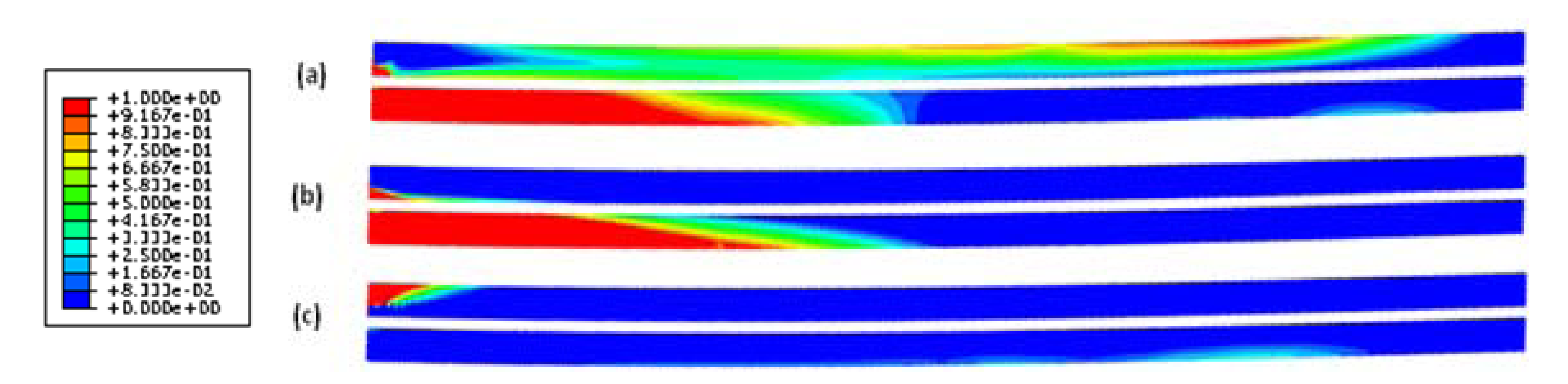
Figure 5, reveals that most of the damage occurs in the inner, non-impact layer, and less damage at the impact zone. The web-shaped damage and star-shaped damages have higher values on the non-impact surface, S4 with the area for D
33 greater than D
11. The shear damage, D
12, due to confined compressive stress, is restricted to on surface S1 in the outer ply.
Figure 3.
Schematic of crack patterns on the glass surface and the corresponding causal stresses (a) star-shaped crack; (b) web-shaped crack.
Figure 3.
Schematic of crack patterns on the glass surface and the corresponding causal stresses (a) star-shaped crack; (b) web-shaped crack.
Figure 4.
Contour plots of damage in laminated glass at 8.4 μs after impact for small missile impact: (a) web-shaped damage D11; (b) star-shaped damage D33; (c) shear damage D12.
Figure 4.
Contour plots of damage in laminated glass at 8.4 μs after impact for small missile impact: (a) web-shaped damage D11; (b) star-shaped damage D33; (c) shear damage D12.
Figure 5.
Contour plots of damage in laminated glass at 3.4 ms after impact for large missile with round end configuration: (a) web-shaped damage D11; (b) star-shaped damage D33; (c) shear damage D12.
Figure 5.
Contour plots of damage in laminated glass at 3.4 ms after impact for large missile with round end configuration: (a) web-shaped damage D11; (b) star-shaped damage D33; (c) shear damage D12.
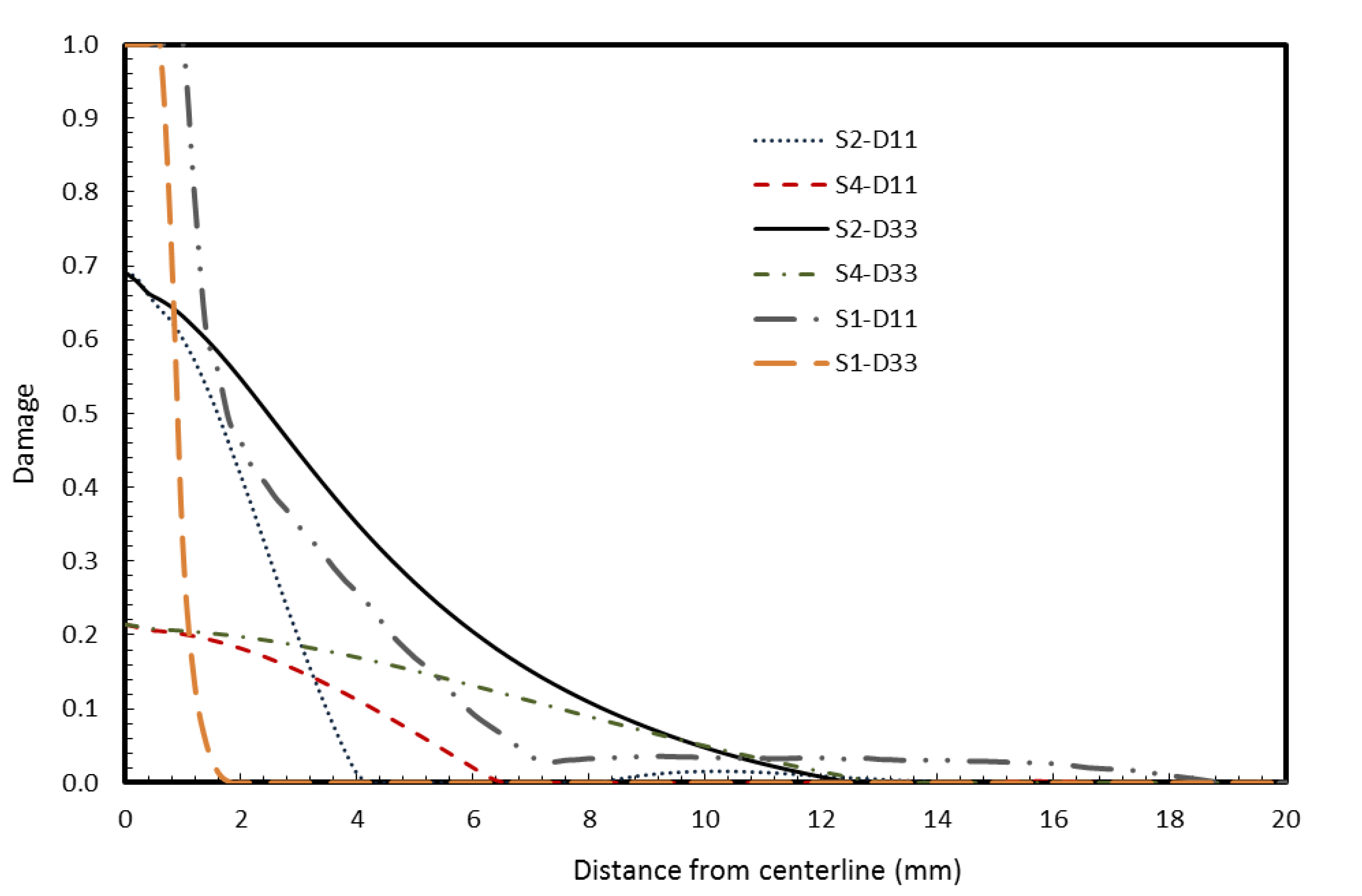
The variation of damage variables for small missile impact is shown in
Figure 6. Total damage is observed at the impact area on surface S1 (impacted surface of outer glass ply, S1) for both D
11 and D
33. This means that there are visible web-shaped and star-shaped cracks on the surface for a radius of 1–2 mm from the centerline of the missile. The maximum value of damage on surfaces S2 and S4 is around 0.7, and hence, the damage is partial—implying no visible cracks. The damage variables D
11 and D
33 for surfaces S2 and S4 for large missiles is shown in
Figure 7. Both surfaces suffer extensive visible damage in this case, with both star and web-shaped cracking predicted to occur over 200 mm from the impact centerline in S4.
Figure 6.
Damage variables D11 (web-shaped) and D33 (star-shaped) at surface S1, surface S2 and surface S4 for small missile impact.
Figure 6.
Damage variables D11 (web-shaped) and D33 (star-shaped) at surface S1, surface S2 and surface S4 for small missile impact.
Figure 7.
Damage variables D11 (web-shaped) and D33 (star-shaped) at surface S2 and surface S4 for a large missile (round end) impact.
Figure 7.
Damage variables D11 (web-shaped) and D33 (star-shaped) at surface S2 and surface S4 for a large missile (round end) impact.
For the small missile impact, the impact surface (S1) is critical and the failure is initiated on that surface, whereas for large missiles, the non-impact surface (S4) is the critical surface for failure. However, for small missile impact, the failure surface can be S1 or S4 depending on the glazing thickness. From
Figure 4, S1 is the critical surface for small missile impact for the glass configuration considered in this study. The damage on S1 is found to be independent of PVB thickness and very weakly dependent on glass ply thickness. This observation supports the earlier study [
9] on low velocity small missile impact on laminated glazing. Hence in the parametric studies described below, S2 is considered as the reference critical surface, and the effect of varying the glazing parameters (PVB interlayer thickness, outer and inner glass ply thicknesses, and panel surface area) on the critical surface for each missile type is studied using the damage variables D
11 and D
33.
4.1. Parametric Study of PVB Thickness
The first parametric study involved comparing the damage of LAG for three PVB thicknesses (0.76 mm, 1.52 mm and 2.28 mm). The damage variables D11 and D33 are noted for surface S2 for small missile and surface S4 for large missile. For the case of small missile impact case shown in
Figure 8, the change in PVB thickness has no significant effect on the damage variables for web-shaped damage D
11 on surface S2. A similar result was observed (results not shown) on the effect of PVB interlayer thickness on star-shaped damage, D
33, on surface S2 for small missile impact, as well surface S4 for large missile with round end configuration. However, for the large missile case shown in
Figure 9, considerable differences in web-shaped damage (D
11) between 0.76 mm and 2.28 mm thicknesses are observed on S4.
Figure 8.
Effect of polyvinyl butyral (PVB) interlayer thickness on web-shaped damage, D11 on surface S2 for small missile impact.
Figure 8.
Effect of polyvinyl butyral (PVB) interlayer thickness on web-shaped damage, D11 on surface S2 for small missile impact.
Figure 9.
Effect of PVB interlayer thickness on web-shaped damage, D11 on surface S4 for large missile (round end) impact.
Figure 9.
Effect of PVB interlayer thickness on web-shaped damage, D11 on surface S4 for large missile (round end) impact.
4.2. Parametric Study of Inner and Outer Ply Thickness
The second parametric study examines the effect of outer and inner glass ply thicknesses, ho and hi, on damage patterns. The baseline case is a symmetric glazing in which both the outer and inner glass plies are of equal thickness (ho = hi = 4.76 mm) and the PVB layer thickness is hp = 1.52 mm. Asymmetric glazing (ho ≠ hi) is also considered. In order to study the response of asymmetric glazing, the thicknesses of the inner and outer plies are varied fifty percent above and below the baseline thickness while keeping the PVB thickness the same (hp = 1.52 mm) as the baseline case. The following five cases are investigated: (i) baseline case ho = hi = 4.76, hp = 1.52 mm; (ii) ho = 2.38, hi = 4.76, hp = 1.52 mm; (iii) ho = 7.14, hi = 4.76, hp = 1.52 mm; (iv) ho = 4.76, hi = 2.38, hp = 1.52 mm; and (v) ho = 4.76 mm, hi = 7.14, hp = 1.52 mm.
For the small missile case, the damage variables D
11 and D
33 on surface S2 (bottom surface, non-impact side, of the outer layer) are shown in
Figure 10,
Figure 11. The damage variables D
11 and D
33 are higher than the baseline case only when the outer layer thickness is decreased in case (ii). The damage variables D
11 and D
33 are lower than or close to baseline case when the inner ply thickness is decreased. Changing the thickness of the inner ply does not seem to have any significant effect on the damage, but the damage can be increased (or decreased) considerably by decreasing (or increasing) the outer ply thickness. Hence for optimum design, the inner ply thickness can be reduced without affecting the overall damage patterns when small missiles are most probable.
For the large missile case, the damage variables, D
11 and D
33 on surface S4 (bottom side of the inner ply) for large missile impact are shown in
Figure 12,
Figure 13. An increase in thickness of either inner or outer ply reduces the damage variables. A decrease in the outer ply thickness results in slightly less damage than if the inner ply thickness is decreased. Hence when weight reduction is required without significantly affecting the damage pattern the outer ply should be chosen for thickness reduction where large missiles are of concern.
Figure 10.
Effect of inner and outer plies thickness on Damage variable D11 (web-shaped) at surface S2 for small missile impact.
Figure 10.
Effect of inner and outer plies thickness on Damage variable D11 (web-shaped) at surface S2 for small missile impact.
Figure 11.
Effect of inner and outer plies thickness on Damage variable D33 (star-shaped) at surface S2 for small missile impact.
Figure 11.
Effect of inner and outer plies thickness on Damage variable D33 (star-shaped) at surface S2 for small missile impact.
Figure 12.
Effect of inner and outer plies thickness on Damage variable D11 (web-shaped) at surface S4 for large missile (round end) impact.
Figure 12.
Effect of inner and outer plies thickness on Damage variable D11 (web-shaped) at surface S4 for large missile (round end) impact.
Figure 13.
Effect of inner and outer plies thickness on Damage variable D33 (star-shaped) at surface S4 for large missile (round end) impact.
Figure 13.
Effect of inner and outer plies thickness on Damage variable D33 (star-shaped) at surface S4 for large missile (round end) impact.
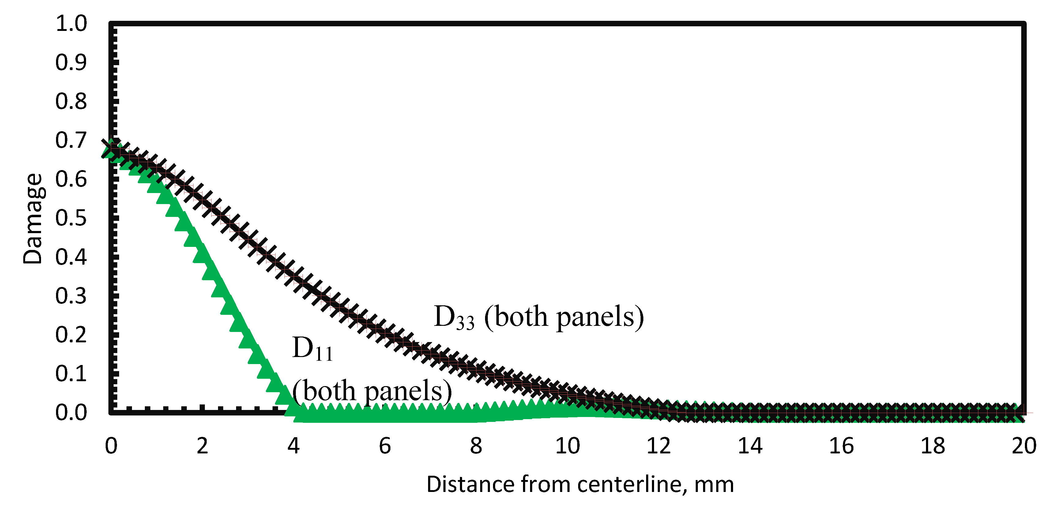
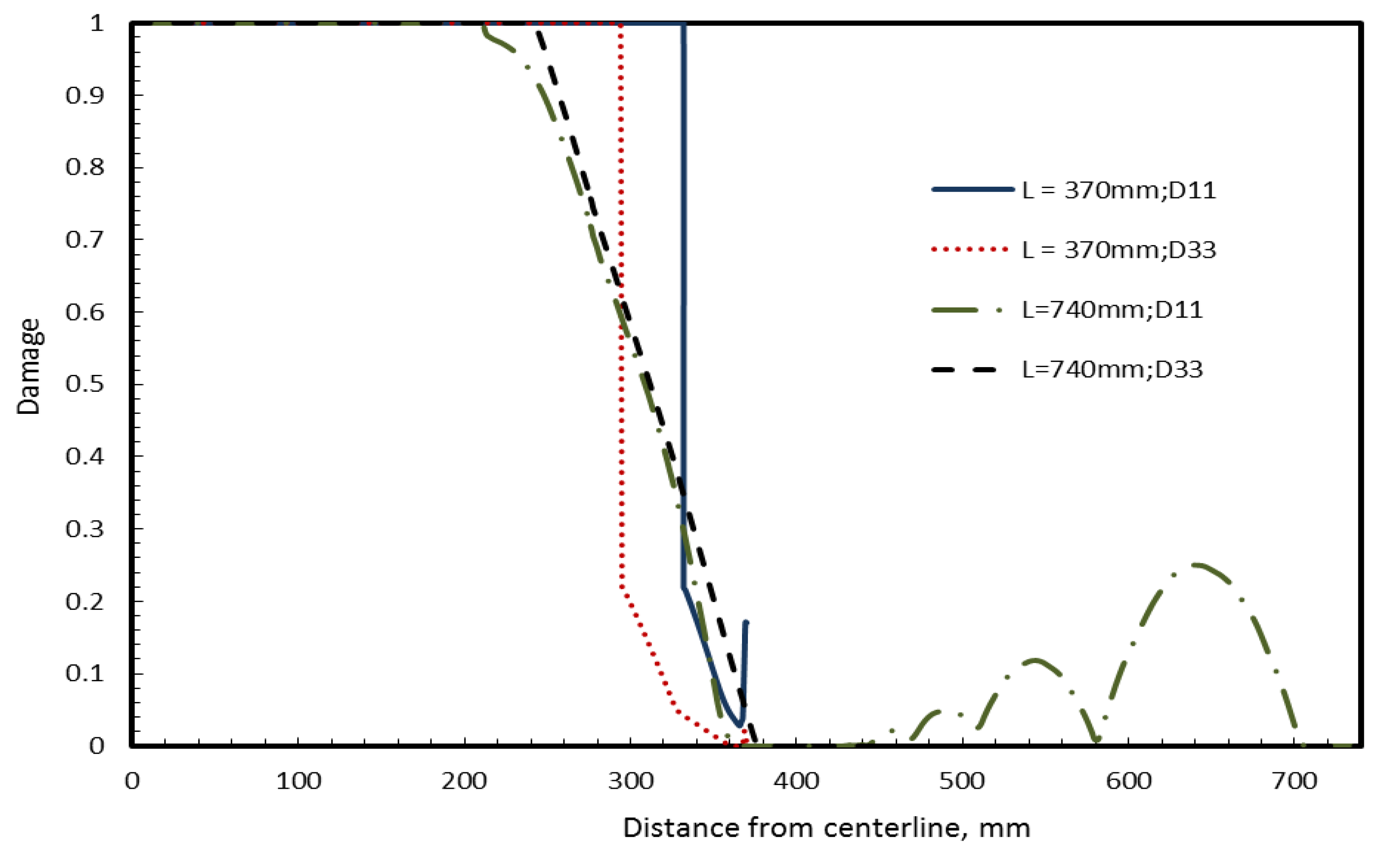
4.3. Parametric Study of Panel Surface Area
The third parametric study is on the effect of the panel surface area on damage patterns. The effect of panel surface area is studied by comparing the panel with baseline dimension (
L = 740 mm radius) with the one having ¼th the area (
L = 370 mm radius) of baseline case. Damage variables D
11 and D
33 on surface S2 for small missile case and surface S4 for the large missile case are presented in
Figure 14,
Figure 15, respectively. For the small missile case shown in
Figure 14, the damage is the same for different areas of the panel as should be expected considering the relative sizes of the panel and the missile. For the large missile case shown in
Figure 15, smaller panels have proportionally more damage than larger ones. This is because the contact force required to induce damage is inversely proportional to the flexibility of the panel, which is proportional to the area of the panel. This result is consistent with earlier observations on laminated automotive glazing subjected to head impact [
16].
Figure 14.
Effect of panel area on Damage variables D11 (web-shaped), D33 (star-shaped) at surface S2 for small missile impact.
Figure 14.
Effect of panel area on Damage variables D11 (web-shaped), D33 (star-shaped) at surface S2 for small missile impact.
Figure 15.
Effect of panel area on Damage variables D11 (web-shaped), D33 (star-shaped) at surface S4 for large missile (round end) impact.
Figure 15.
Effect of panel area on Damage variables D11 (web-shaped), D33 (star-shaped) at surface S4 for large missile (round end) impact.


 representing the matrix of undamaged material and
  representing the added influence of damage. The matrix components [14] are given as:


