Abstract
In Italy, most of the residential buildings (77%) were constructed before 1981, when only 25% of the national territory was classified as seismic. Further, the first provisions addressing thermal performance criteria were introduced in 1991, when about 88% of the existing Italian buildings had already been realized. Therefore, the Italian building stock is characterized by a large deficit in terms of both seismic capacity and thermal insulation. The large number of buildings having inadequate performance, both seismic and thermal, calls for rehabilitation interventions that are based on an integrated and sustainability-oriented approach. In the paper, the influence on seismic performance deriving from some retrofitting techniques, generally adopted to enhance the thermal performance of infill walls, has been evaluated. A common residential RC building representative of existing buildings designed only for vertical loads has been studied. The seismic performances have been evaluated through Incremental Dynamic Analyses (IDA). A first comparison is related to a thermal retrofitting intervention made by replacing the existing masonry infill walls with new elements that are able to ensure an adequate thermal protection. Further, a retrofitting intervention based on the “double skin” technique, where new infilled RC frames are added and connected to the existing ones, has been investigated in terms of seismic and thermal performance.
1. Introduction
Whereas in the past the choice to demolish and replace old constructions that did not meet both modern functional requirements and new safety standards was rather common, more attention is currently devoted to rehabilitating existing structures, thus extending their service life for as long as possible [1]. Indeed, the retrofitting of existing structures is an increasingly leading branch in the construction sector. Its rate has increased steadily during the last 30 years going from 20% in the ‘80s to the current 40% and it can be expected that this trend will continue in future taking into account the features of the existing building stock [2].
The current EU Regulation on Construction Products [3], in addition to the six essential requirements for construction works considered in the previous version [4], includes the 7th requirement accounting for the “sustainable use of natural resources”, stating that “The construction works must be designed, built and demolished in such a way that the use of natural resources is sustainable and in particular ensures the following:
- (a)
- reuse or recyclability of the construction works, their materials and parts after demolition;
- (b)
- durability of the construction works; and,
- (c)
- use of environmentally compatible raw and secondary materials in the construction works”.
According to point (b), in achieving the results stated at the 1st basic requirement “mechanical resistance and stability” [3], particular attention should be devoted to durability, acting in such a way that construction performances are maintained as long as possible.
Besides, in the forthcoming revision of the set of ten EN-Eurocodes towards their second generation, one of the key priorities concerns the evaluation and rehabilitation of existing structures [2].
With respect to the condition of the existing building stock, in Europe there are about 25 billion m2 of useful floor space (data relevant to 27 EU member states in 2011 plus Switzerland and Norway). 75% of this surface is residential building stock (64% single family houses, 36% apartment blocks) and 25% consists of more complex and heterogeneous non-residential buildings. More than 40% of residential buildings were constructed before the ‘60s, with the largest shares of older buildings in UK, Denmark, Sweden, France, Czech Republic, and Bulgaria [5]. As a result, beyond the well-known deficit of seismic protection dramatically pointed out by past earthquakes, also the energy performance of the European buildings is generally poor. In fact, the levels of energy consumed in buildings is one of the main CO2 emission sources in Europe.
Specifically, in Italy, most of the residential buildings were constructed before 1981 (77%), when only 25% of the national territory was classified as seismic [6]. These values have been calculated by combining the results obtained from the last census of the Italian population and residential buildings (ISTAT2011 [7]) and the share of the territory classified as seismic before 1981. Consequently, these buildings were not designed considering seismic actions, therefore they are generally characterized by high vulnerability, as clearly shown by recent earthquakes (e.g., L’Aquila 2009, Emilia 2012, central Italy 2016) [8,9,10,11,12]. Beyond historic masonry structures, a large proportion of the Italian building stock designed without seismic criteria is made up of Reinforced Concrete (RC) structures constructed after the Second World War. In addition to seismic deficit, the Italian building stock is also characterized by a large deficit of thermal insulation. In fact, the first regulation addressing thermal performance criteria was introduced in 1991 [13], when about 88% of the present Italian building stock had already been realized. After this, as reported in detail at Section 3, modern rules focusing on the reduction of heat loss and, more generally, on the improvement of energy performance were introduced both in the design of new buildings and in the rehabilitation of existing ones.
In the past, several techniques able to reduce seismic vulnerability e.g., [14,15], as well as heat loss e.g., [16,17] have been set up and implemented. Generally, these techniques deal separately with the different components of the building at hand, in order to increase either the seismic or thermal performance. Nevertheless, as a consequence of the large quantity of buildings having inadequate performance both seismic and thermal, an integrated approach in the design of interventions (i.e., able to provide simultaneously multiple beneficial effects) is strongly required to perform a sustainable policy of building rehabilitation. On the contrary, uncoupled rehabilitation solutions could be ineffective in terms of either seismic risk mitigation or energy saving. As a matter of fact, in earthquake prone areas thermal rehabilitation interventions designed neglecting seismic actions could determine an increase of the exposure in terms of building value. Similarly, seismic retrofitting interventions could compromise living comfort and maintenance costs since they can determine higher heat loss (e.g., by simply adding RC shear walls). Integrated approach in the design of both seismic and thermal rehabilitation of buildings is a recent topic, scarcely investigated by researches in the past. Among these, [17,18,19] analysed different aspects regarding both assessment and retrofit design in the framework of an integrated approach that is aimed to energy efficiency and earthquake strengthening of buildings. In particular, in [19] environmental and seismic impact metrics are translated into common financial decision-making variables by defining discrete classes of both earthquake resilience and energy efficiency, similarly to what is a common practice when evaluating the energy and environmental performance of buildings. According to the authors, an integrated approach is always advantageous when compared to investment in only earthquake resiliency or energy efficiency.
Integrated design of interventions can involve both masonry and RC existing buildings, although masonry buildings have in general more restrictions to a structural intervention [20]. In RC framed structures, infill walls play a key role in both seismic and thermal performance. Several studies [21,22,23,24] showed the benefit on the seismic response when infill panels are regularly arranged both in plan and in elevation, while poor seismic performance can be expected in case of irregular arrangement of infill panels [25,26,27,28]. Furthermore, due to their lower deformation capacities when compared to the surrounding structural members, infill panels in framed structures suffer earlier damage under low inter-storey drift values, thus determining the loss of functionality up to unusability of the affected buildings, as confirmed by recent Italian seismic events [29]. Moreover, in-plane damage can reduce the out-of-plane capacity of infill panels up to collapse, thus causing severe risk for life safety [30]. As for thermal performance, infill walls are one of the most scattering components in terms of heat loss, due to both their constituent materials and their large area.
In order to increase the seismic performance of infill walls, some authors analysed retrofitting interventions based either on reinforcement meshes placed on one/both faces of walls effectively connected to frames [31,32] or innovative solutions adopting sliding joints to reduce the infill-frame interaction [33,34,35]. The former solution is also able to influence the building performance as a whole [31,36], because seismic response could be similar to a frame-wall system with the related advantages and drawbacks. Generally, connecting infill panels to the surrounding RC frames provides an increase of the structure stiffness and resistance. However, the higher base shear can drive excessive stress concentrations on the foundation structure as well as on beam-column joints. It is worth noting that in all the above-mentioned solutions, no effects on the thermal performance have been accounted for.
Coherently, with an integrated approach, in the paper the influence on the seismic performance of some retrofitting techniques generally adopted to enhance the thermal performance of infill walls has been investigated. To this end, Incremental Dynamic Analyses [37] on some existing RC building types have been carried out dealing with a case study structure analysed both as-built and after some possible rehabilitation interventions. Rehabilitation is based essentially on the replacement of the existing masonry infill walls with new elements able to ensure an adequate thermal protection, according to the current thermal insulation requirements. Additionally, the capability in both seismic and thermal rehabilitation through the double skin technique [38] has been analyzed by considering new infilled frames that are effectively connected to the existing ones.
2. Review of the Italian Energy Efficiency Rules
In this section, specific attention is firstly paid to the development of energy efficiency rules in force in Italy in the past. After, more recent and current Italian requirements are reported noting that they substantially comply with those in force in other European countries (e.g., France, United Kingdom, Germany), being based on common UE directives.
The first Italian rule addressing thermal insulation criteria in building design was introduced in 1976 [39], as a consequence of the first energy crisis deriving from the worsening conflict in the Middle East occurred in that period. It provides lower threshold values of the thermal insulation capacity of the building shell, in order to reduce heat loss, and, consequently, energy demand. In 1991, as a consequence of the first study on the “greenhouse effect” and to reduce the import of energy from the Middle East area, the National Energy Plan and then the Law 10/1991 [13] were issued. This latter document introduced the energy performance of buildings along with new thermal criteria for the design of the building shell and the management of energy facilities.
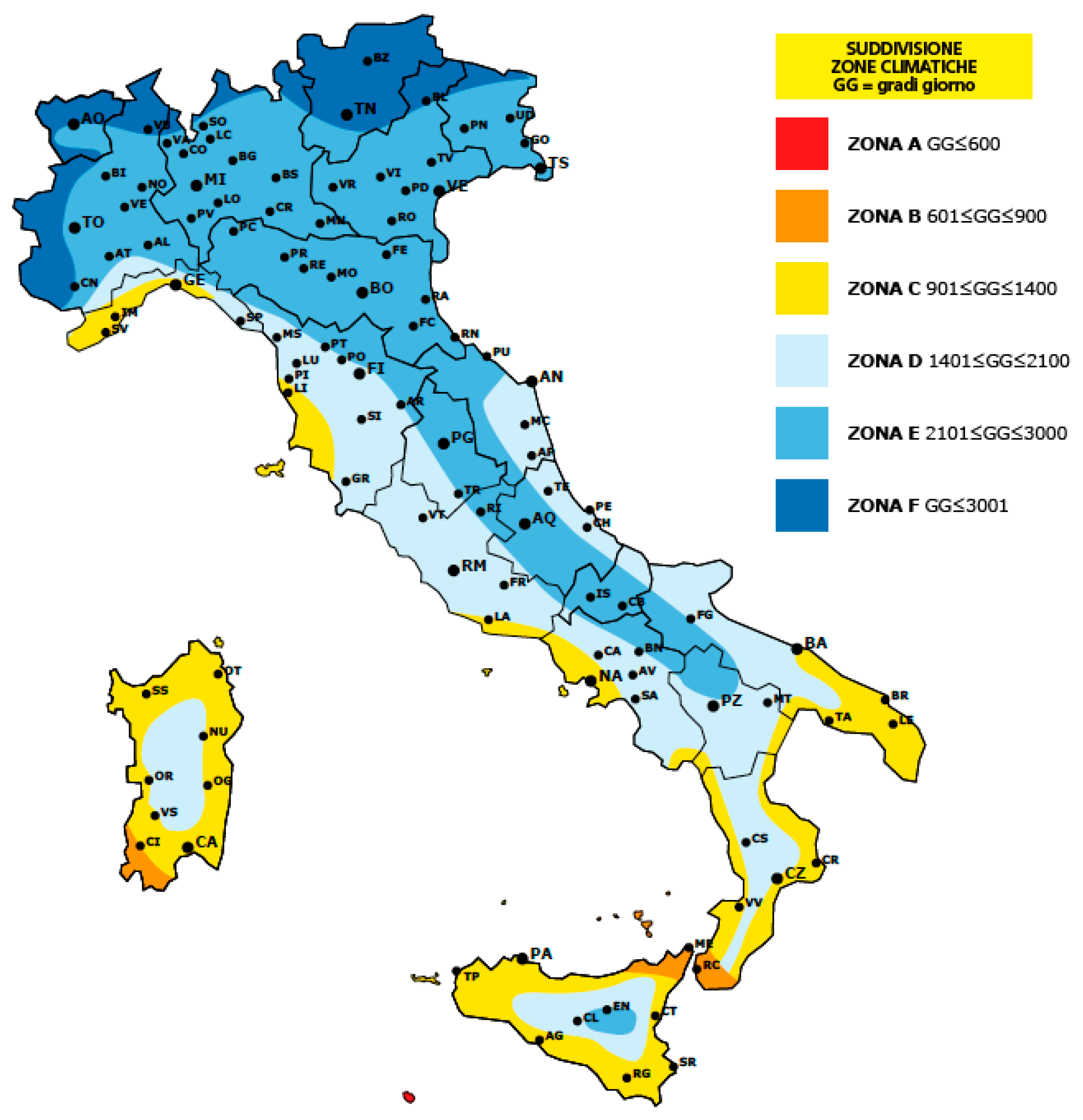
In this framework, the Presidential Decree 412/1993 [39] identified six different climatic zones in the Italian territory (from A to F, Figure 1) as a function of a parameter named GG (degree day, computed as the sum throughout a year of the daily difference between the mean value of the expected external temperature and the standard room temperature).
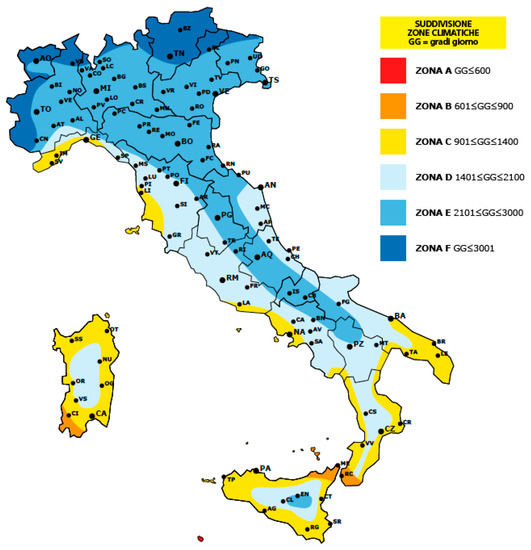
Figure 1.
Climatic zonation according to the Presidential Decree 412/93 [40].
In 2002, the European Union issued the directive 2002/91/CE [41] as a consequence of the Kyoto protocol [42]. This document introduced the Energy Performance Certificate of a Building in which all energy uses (e.g., heating, cooling, lighting, domestic hot water) need to be accounted for in the energy performance assessment.
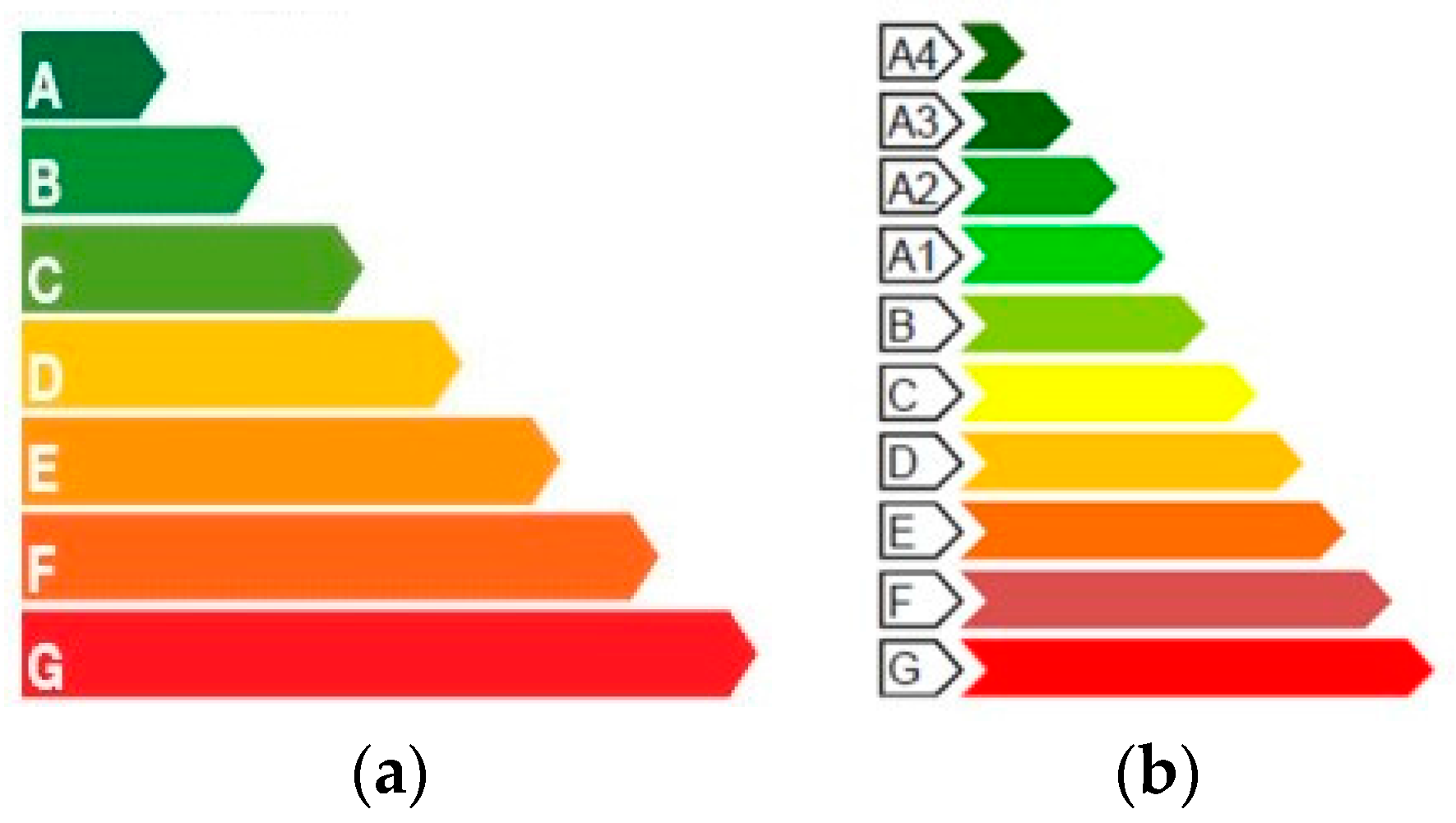
In Italy, this directive was adopted through the Legislative Decrees 192/2005 [43] and 311/2006 [44], which provided some criteria to improve the energy performance of buildings, as well as to encourage the use of renewable energy sources. Furthermore, they provided threshold values in terms of thermal transmittance of the vertical building components (e.g., infill walls) for the different climatic zones (Figure 1). For example, for zone E (which includes a large part of the Italian territory, see Figure 1), the thermal transmittance value is 0.46 W/m2K. In 2009, the Presidential Decree 59 [45] introduced the guidelines to prepare the Energy Performance Certificate. Specifically, seven classes (performance classes from A to G, Figure 2a) in terms of energy demand required for heating and domestic hot water were provided to assess the energy performance of buildings.
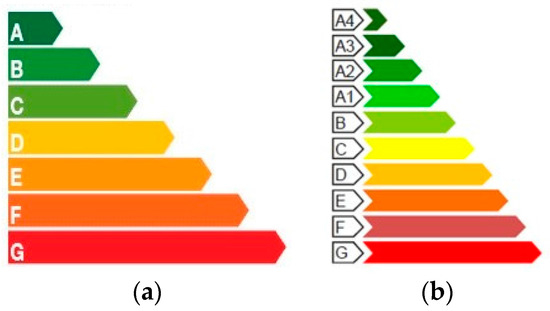
Figure 2.
Performance classes in accordance to: Presidential Decree 59/2009 [45] (a); Ministerial Decree 26 June 2015 [48] (b).
After the European Directive 2010/31/EU [46], the Legislative Decree 28/2011 [47] issued a new release of the energy performance certificate, which is mandatory in case of buying and selling of a house/building.
At present, the energy performance of buildings is evaluated in accordance with the Ministerial Decree 26 June 2015 [48], in which an upgraded version of the energy performance certificate document is provided along with new threshold values of thermal transmittance values (Table 1). The energy performance is evaluated according to 10 different classes (Figure 2b), with each one defined as a function of the energy demand deriving from non-renewable sources, EPgl,nr, computed with regards to a reference standard building (i.e., having performance class A1).

Table 1.
Thermal transmittance values for opaque components (e.g., infill panels) according to the Italian Ministerial Decree 26 June 2015 [48].
3. Mechanical and Thermal Properties of Infill Types
Infill walls play a key role in RC framed structures, in terms of both seismic and thermal performance. In fact, beyond the well-known effects on the seismic behaviour [21,22,26], as a consequence of both the materials’ properties that are generally adopted in practice and the large area of the building shell covered by them, infill panels represent one of the main sources of heat loss.
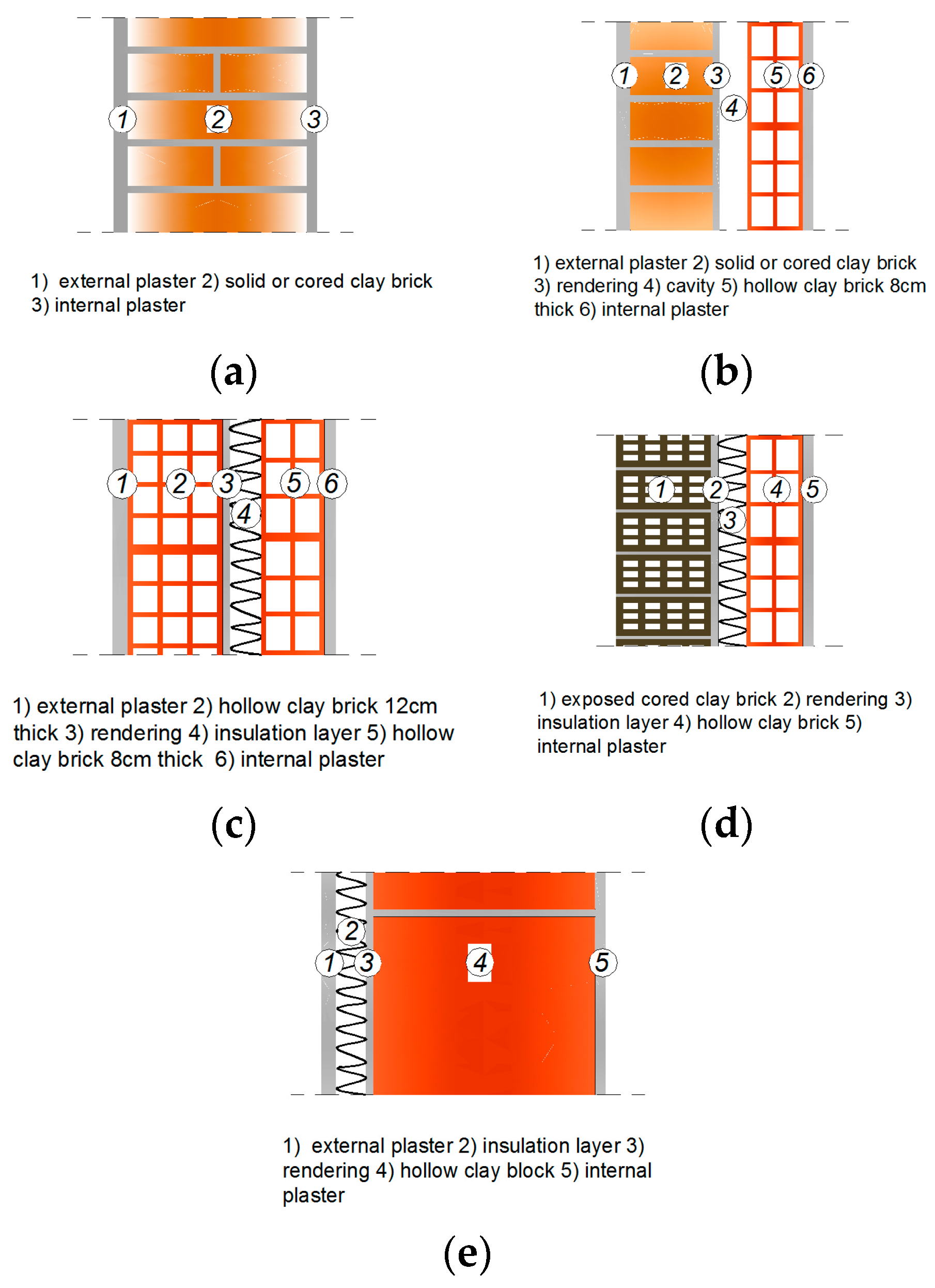
In Italy, as well as in many European countries, different infill types can be found [49,50]. Specifically, in the ‘30s–‘40s infills were typically organised in a single layer, generally using brick masonry or, less frequently, stone masonry having thickness 30 ÷ 60 cm (Figure 3a). In such a case, the infill revealed itself to be an additional structural system with respect to seismic loads, providing a considerable collaboration to RC frames. Regarding mechanical properties, generally the mean compressive strength values fm range between 2.4 and 4.0 N/mm2, the elastic modulus E is around 3500–6000 N/mm2, whereas the weight per unit of volume is around 15 kN/m3 [51]. With reference to the double-layer type with solid bricks, the thermal transmittance value (so-called U-value) is around 1.88 W/m2K [52].
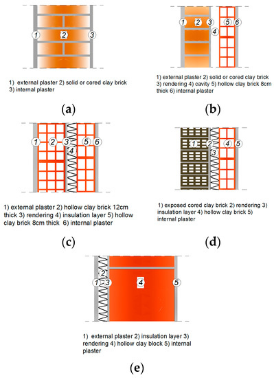
Figure 3.
Typical infill types used in Italian Reinforced Concrete (RC) buildings: (a) single layer of solid clay brick; (b) cavity wall with solid and hollow clay bricks; (c) cavity wall with two layer of hollow clay bricks; (d) cavity wall with exposed cored and hollow clay bricks; and, (e) single layer of hollow clay brick with high insulation performance.
Starting from the ‘50s, as a result of the increasing attention to thermal and sound insulation requirements, infills were typically organised in two layers, having a total thickness of about 30 cm (cavity walls). Both the external (12 cm thick) and internal (8 cm thick) layers were made up of masonry bricks, solid (or cored) and hollow, respectively (Figure 3b), placing mortar layers only along the horizontal bed-joints. Cavity thickness was generally 5–10 cm. Due to the presence of hollow bricks, these infill panels have generally lower values of mechanical properties but exhibit better thermal insulation. In fact, the mean compressive strength of the hollow clay brick is in the range of 1.2–2.2 MPa, the elastic modulus is 800–2000 MPa and the weight per unit of volume is 8–9 kN/mc [31,53,54,55]. With reference to the thermal insulation properties, the U-values range from 1.590 W/m2K (in case of external layer made up of solid bricks) to 1.31 W/m2K in case of hollow brick [56]. These thermal properties refer to the empty cavity types.
Since the ‘70s, as a consequence of the first previsions on energy saving, cavity has been infilled with different materials (e.g., glass wool, mineral wool) having high thermal insulation properties (Figure 3c). For example, the U-value becomes 0.71 W/m2K for the cavity wall type with hollow bricks above described and cavity infilled by glass wool 4 cm thick.
For more recent buildings, in order to achieve better performance in terms of thermal insulation (Figure 3d), the two layers have larger thickness. In particular, the external layer is made up of cored bricks 16–30 cm thick, usually without external plaster (exposed brick type). The compressive strength of the cored bricks is generally in the range 5–8 MPa, the elastic modulus is 3500–5500 MPa, and the weight per unit of volume is 9–13 kN/m3 [57,58]. As for thermal properties, the transmittance value is about 0.3 W/m2K [59] for infill walls made up with an internal layer of hollow brick 12 cm thick, insulation thermal layer of glass wood and exposed cored brick 20 cm thick. At present, as a consequence of the need to shorten the execution time, a single-layer type with hollow bricks having high insulation performance is frequently used (Figure 3e). For bricks that are 30 cm thick, compressive strength (along the holes) is 5–7 MPa, elastic modulus 4400–5200 MPa [32], and the weight per unit of volume is 9–12 kN/m3. Using a 6 cm thick insulation layer of glass wool, the thermal transmittance value decreases to 0.25 W/m2K [56].
4. Seismic and Thermal Rehabilitation: An Application of Integrated Approach
In the seismic design of new buildings, as well as in the retrofitting of existing ones, infill walls are generally considered non-structural elements, and, consequently, neglected in the structural analyses and safety verifications. As a matter of fact, infills provide a remarkable contribution to the lateral load bearing capacity in terms of strength, stiffness, and energy dissipation, especially in RC buildings designed only to gravity loads. However, these components of the building shell are currently designed to ensure adequate thermal and sound insulation, but this objective has been effectively pursued only in the last decades. Therefore, in most of the existing buildings infill walls are one of the most scattering sources in terms of heat loss.
Looking at interventions based on an integrated approach, the role of infills walls is crucial and needs to be adequately taken into account. In fact, generally the better the thermal insulation characteristics the higher the mechanical properties’ values (see Section 3, in particular for the more recent infill types). Therefore, interventions that are aimed at satisfying requirements in terms of energy saving by replacing existing infill panels with new ones having better thermal insulation characteristics could be properly adopted also to improve seismic performance. As a result, energy and seismic assessment should be jointly performed in order to effectively address the whole retrofit design.
To describe the main steps of such a procedure, an application to a common residential RC building representative of existing buildings designed only for vertical load, is hereafter proposed. The integrated approach has been applied by considering three different configurations, whose performances have been assessed and compared, namely:
- C1
- as-built;
- C2
- rehabilitated by replacing the external layer of the as-built infill walls with a new panel having better thermal insulation properties; and,
- C3
- rehabilitated by considering a double-skin solution where new RC frames are externally added and properly connected to the existing RC structure.
4.1. Building Type Description and Modelling
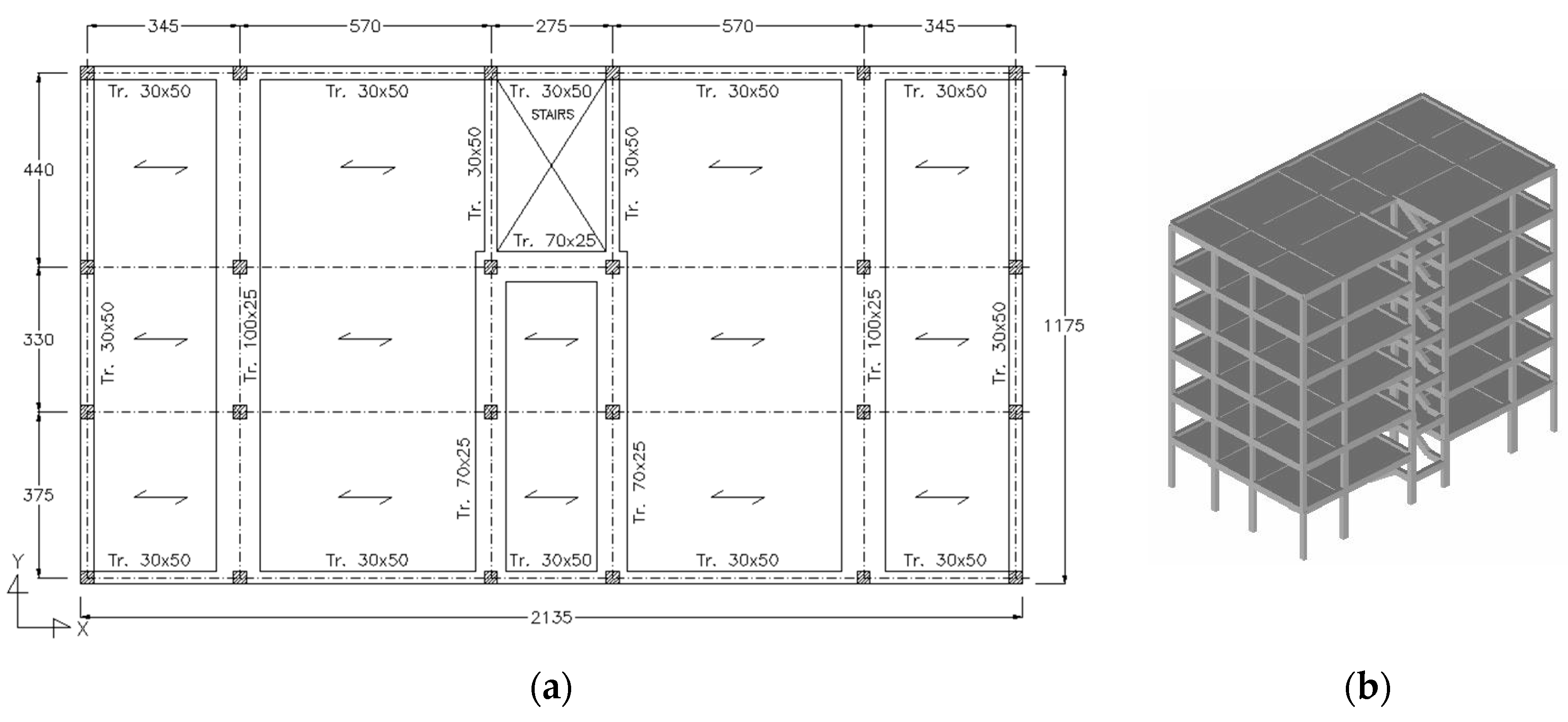
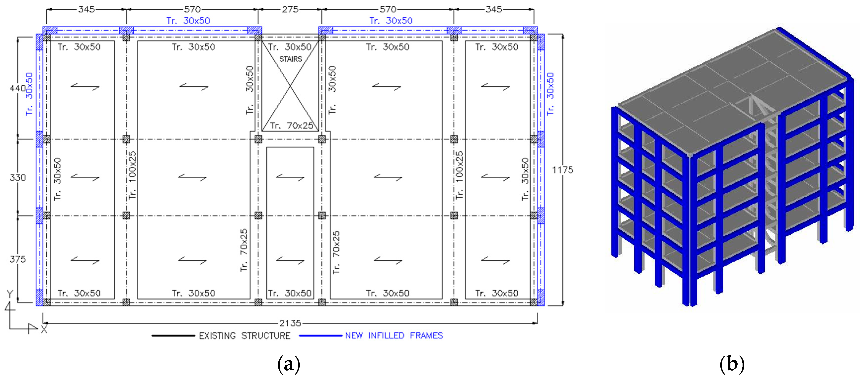
The building under study is a six-storey RC framed structure belonging to the post-1971 Italian building stock designed only to vertical loads by means of the simulated design procedure proposed in [26]. The structural type has a rectangular shape in plan (Figure 4) with total dimensions 21.4 × 11.8 m2 (X and Y direction, respectively) and constant inter-storey height equal to 3.05 m. As a consequence of the orientation of slab (25 cm thick), vertical load resisting beams are put only along the transversal direction Y (3 bays), with external rigid beam (cross-section dimension equal to 0.30 × 0.50 m2), and internal flexible ones (0.70 × 0.25 and 1.00 × 0.25 m2). Along the longitudinal direction X, the structure has five bays with rigid beams (0.30 × 0.50 m2) only along the exterior frames and with one-way RC slab along the interior frames. Columns are generally cross-section dimensions equal to 0.30 × 0.30 m2, except for some elements of the lower storeys whose dimensions range from 0.30 × 0.40 to 0.30 × 0.55 m2. The staircase is placed in a symmetric position in relation to the Y direction and has knee-type beam with dimension 0.30 × 0.50 m2.
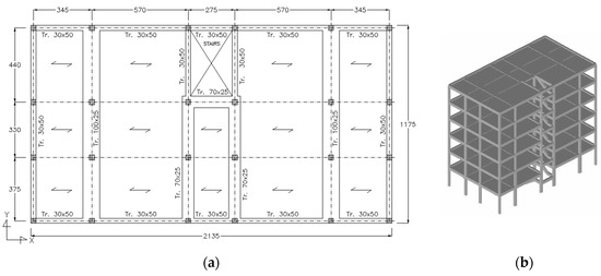
Figure 4.
In plan layout of the building type under study (a) and three-dimensional (3D) view of the model (b).
As expected in the considered construction period, double-layer masonry infills consistent with the sketch of Figure 3c are present, with 8 cm (internal layer) and 12 cm (external layer) thick panels of hollow brick masonry (void percentage in the range 45–55% according to [60]) and empty cavity (10 cm thick). Mechanical and thermal properties correspond to those reported at Section 3 for type b) infills. In the case of partial replacement of the external panel (configuration C2), a common cored brick (void percentage in the range 15–45%, according to [60]) has been considered, whose properties are consistent with the infill type d) described at Section 3. A similar brick type has been considered in the new infilled frames of configuration C3.
The structural analyses were performed by using the finite element code OpenSees [61]. A macro-modelling based on lumped plasticity was adopted to describe the nonlinear seismic behaviour of RC members. At both ends of each structural member, a bending moment–rotation (M-θ) relationship was defined by adopting the Ibarra, Medina and Krawinkler model [62] available in the OpenSees platform. Backbone parameters were evaluated according to the expression provided by Haselton and Deierlein [63]. When a brittle failure was predicted (e.g., this typically occurs in the short columns of the staircase structure), the above-mentioned M-θ relation was appropriately modified considering a bending moment value calculated as a function of the ultimate shear capacity evaluated, according to the Sezen model [64]. The Elwood and Moehle model [65] was also considered for the axial-load failure after shear failure. On the basis of the mechanical properties of the constituent materials typically found in real buildings of the period under consideration, mean concrete strength value (fcm) equal to 20 MPa, and mean steel strength value (fym) equal to 400 MPa were assumed in evaluating the structural capacity.
Infill panels were modelled by using an equivalent diagonal strut whose area was determined by multiplying the panel thickness (t) by an equivalent width (w), according to the Bertoldi model [66]. The axial force-displacement relationship (F-d) set up by Bertoldi et al. [66] was adopted for the non-linear and degrading behaviour. Different compressive strength values are considered for the infill type present in the different configurations. Specifically, in the C1 configuration (hollow clay brick), the compressive strength is 1.1 MPa, and the elastic modulus is 1800 MPa. In the configurations C2 and C3 (cored brick), the mechanical properties of the strut modelling the new infill panels are equal to 4.0 MPa and 3300 MPa, respectively, for the compressive strength and the elastic modulus value. Inter-storey drift values proposed by Masi et al. in [67] have been considered to define the different branches of the F-d relationship.
In order to take into account the effect due to the openings frequently present in the infill walls of residential buildings, both stiffness and ultimate strength have been reduced through the Decanini et al. expression [68].
In case C3, new infilled frames have been modelled by putting beam (for resisting members) and truss (for infill walls) finite elements, in parallel with the corresponding ones of the existing structure.
4.2. Energy Assessment of the As-Built Building
Energy assessment has been carried out according to the Italian standard UNI/TS 11300-1 [69], as prescribed in [48] that requires: (i) to check the thermal transmittance value of each dispersing component (e.g., infill walls) is lower or equal than the threshold value provided for the climatic zone at hand; and, (ii) to evaluate the energy performance as a function of the required energy demand.
In the building type under study, thermal transmittance is 1.31 W/m2K, evaluated by considering all the layers of the infill panel according to the equation U = 1/ΣRi, where Ri is the thermal resistance of the i-th losing layer evaluated through the si/λi ratio, where λi is the thermal conductibility and si is the thickness. This value can be compared with the U threshold values required by [48] for the different zones (see Table 1).
To this end, an index β able to represent the actual thermal deficit can be defined as the ratio between the transmittance threshold value prescribed for the zone at hand (demand, UD) and that evaluated for the considered infill type (capacity, UC):
β = UD/UC
In such a way, β values larger than 1 identify the buildings having adequate performance with respect to each climatic zone.
For the building under study, considering the climatic zone E (UD = 0.30 W/m2K), which includes a large part of the Italian territory, and an infill type b (Figure 3, UC = 1.31 W/m2K), β is equal to 0.23, thus is largely lower than 1.
Assuming for the other losing components common values of the thermal transmittance according to the construction period (i.e., windows: U = 5.5 W/m2K; roof: U = 1.75 W/m2K; ground floor: U = 1.4 W/m2K), energy demand (evaluated by adopting the TherMus software [70], and considering heating only) is about 74 kWh/year per unit of area (in square metres) of each storey. Consequently, accounting for that the classification provided in the Italian energy code [48] is related to the energy demand, the value above reported (74 kWh/year per unit of area) falls in the range of performance assigned to class F.
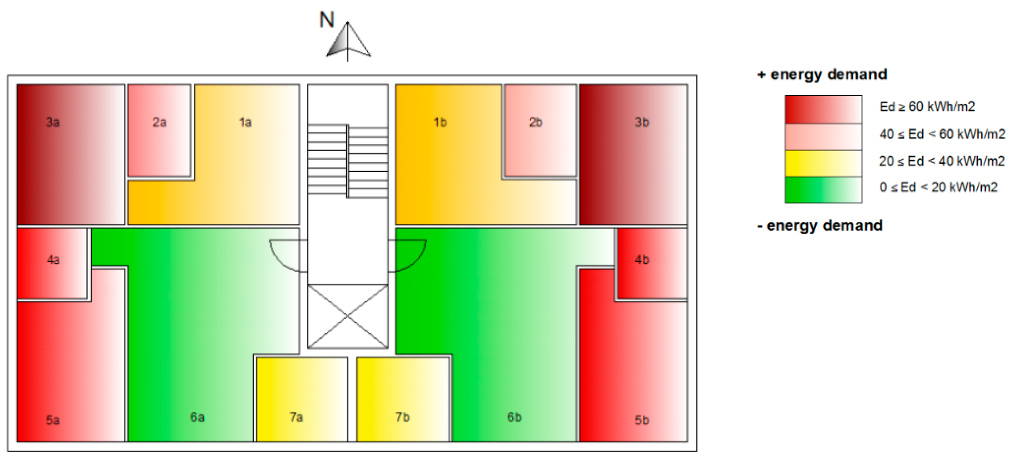
In Figure 5, a colour map highlights the energy demand values evaluated for each room of the typical building floor, under the assumption of a full thermal insulation between adjoining rooms. As a consequence of the in-plan orientation, high values of the energy demand are found for the rooms along the north-facing façade, as well as to the east- and west-facing façades. On the contrary, a lower energy demand is required to the rooms having south exposure. These results need to be taken into account in order to maximize the effectiveness of thermal retrofitting.
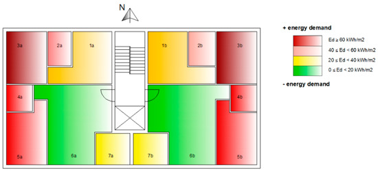
Figure 5.
Colour map of the energy demand (Ed) evaluated for the “as-built” configuration.
4.3. Seismic Assessment of the As-Built Structure
Seismic performance of the structure under study has been evaluated by Incremental Dynamic Analysis (IDA) [37]. IDA is a parametric method of analysis where a structure is subjected to a set of accelerograms of increasing intensity up to collapse, thus the dynamic response in non-linear range can be effectively evaluated. In the present study, ten accelerograms defined in the RINTC project [71,72] for L’Aquila site (soil type A, i.e., rock or other rock-like geological formation according to the Italian and European seismic code) have been considered for each in plane direction. Table 2 shows the initial values of the main seismic parameters of the considered accelerograms. Each accelerogram is progressively scaled up to the structural collapse (dynamic instability). In particular, for each time-history, ten increasing levels of amplification from 1 to 50 have been considered.

Table 2.
Seismic parameters of the considered records in terms of peak ground acceleration (PGA) and velocity (PGV), maximum spectral pseudo-acceleration (Sa,max), and Housner Intensity.
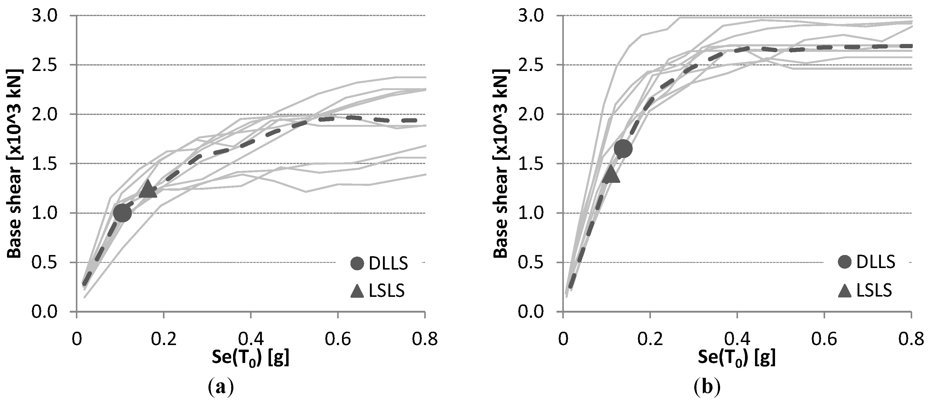
Results of the each dynamic analysis have been plotted in terms of spectral pseudo-acceleration value corresponding to the scaling factor of the record and the maximum base shear value. To this purpose, in Figure 6, the relationships between the spectral pseudo-acceleration (Se(T0), evaluated at the fundamental period of the structure, equal to 0.85 s), and the maximum base shear obtained from each IDA analysis, are displayed separately for X (Figure 6a) and Y (Figure 6b) in-plane direction. Dashed lines refer to the median value (median curve). In the same figure, the values related to both Damage Limitation (DLLS) and Life Safety (LSLS) Limit State, calculated in accordance with the Italian code, are also displayed. DLLS has been verified by comparing the maximum inter-storey drift value recorded during the time history analysis with an assumed threshold value that is equal to 0.3%, as proposed in [58]. LSLS is deemed to be exceeded considering the seismic intensity at which the chord rotation demand on the plastic hinge of the weaker element reaches the ultimate capacity, conventionally assumed at 20% strength loss. This value substantially complies with the provisions in [58], as well as is coherent to the performance found in experimental investigations (e.g., [73]).
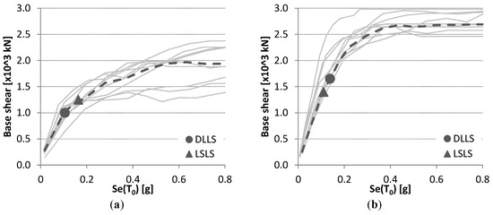
Figure 6.
Spectral pseudo-acceleration vs. maximum base shear curves obtained for X (a) and Y (b) direction by considering all Incremental Dynamic Analysis (IDA) analysis (solid line) and median values (dashed line).
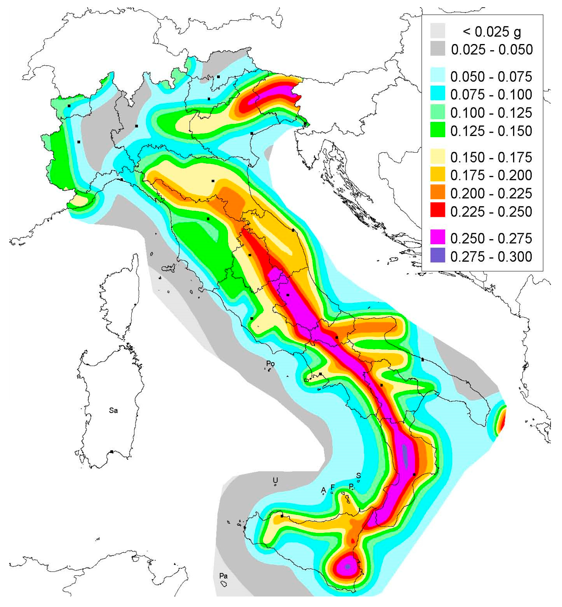
In X direction, the seismic intensity value that is related to DLLS and LSLS is equal to 0.105 g and 0.163 g, respectively. Different performances are found in the Y direction, where staircase substructure determines: (i) a greater stiffness with respect to the X direction (the fundamental period values are Tx = 0.85 s and Ty = 0.77 s, respectively, for X- and Y-in plane directions); and, (ii) a brittle behaviour in the short columns. In terms of the seismic intensity relevant to the considered limit states, in the Y direction DLLS is achieved at 0.138 g, that is about 30% higher than that evaluated in the X direction (0.105 g), whereas a remarkably lower value (0.110 g) than that evaluated in the X direction (0.163 g) is found for LSLS. To estimate the seismic deficit, the above reported intensity values (capacity, Se,C) have been compared with different intensity values (demand, Se,D) consistent with the Italian hazard map [74] (Figure 7) and evaluated in terms of spectral pseudo-acceleration values at the fundamental period of the structure (T0 = 0.85 s) for return period TR = 475 years.
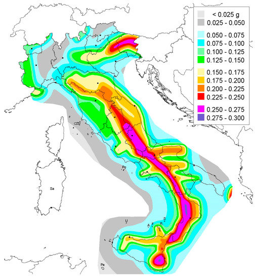
Figure 7.
Italian seismic hazard map in terms of PGA according to [74].
Specifically, in Table 3 intensity values representative of low- (i.e., Milano), mid- (i.e., Napoli), and high-seismicity zones (i.e., L’Aquila) are compared with the computed capacity values (the minimum value between X and Y direction has been considered). As a measure of the seismic deficit, the ratio between the capacity and the demand value (α = Se,C/Se,D) for both limit states has been computed. In line with the current seismic code requirements for new buildings, safety is verified for α values higher than or equal to 1.0, while progressively lower values can be considered representative of increasing seismic deficit conditions.

Table 3.
Comparison between capacity and demand values, evaluated for both Damage Limitation (DLLS) and Life Safety (LSLS) for different seismic zones.
The results in Table 3 show that, for the DLLS verification, the capacity value is higher than the intensity values relevant to all seismic zones, that is αDL is always higher than 1, therefore good performance of the non-structural elements (i.e., infill walls) appears to be sufficiently guaranteed (i.e., maximum inter-storey drift value recorded during the time history analysis is lower than or equal to 0.3%). On the contrary, a remarkable seismic deficit is found verifying LSLS, in particular for the higher seismic levels. In fact, αLS is equal to 0.76 and 0.38, respectively, in mid- and high-seismic zones, thus asking for a strengthening intervention to guarantee adequate structural safety. It is worth highlighting that the seismic deficit is mainly due to bending moment failure in beam members and due to shear in the short columns of the staircase structure.
4.4. Design of Thermal and Seismic Rehabilitation
In the previous analyses, a significant deficit in terms of both thermal insulation and seismic resistance has been found for the building under study in some seismic and climatic zones. With regards to thermal deficit, heat loss is mainly due to the poor thermal transmittance value of infills, while seismic deficit is relevant only to the Life Safety limit state with failure due to bending moment in beam members and due to shear in the short columns of the staircase structure.
In the following, a rehabilitation intervention based on the proposed integrated approach is described for the building under study aimed at achieving adequate performance in climatic zone E and in the different seismic zones considering seismic actions related to return period TR = 475 years (i.e., the return period typically assumed for the LSLS verification of ordinary buildings).
Firstly, in order to satisfy the requirements provided by [48], the external panel of infill walls (12 cm thick) has been removed and replaced by a new panel made up of cored bricks 20 cm thick, having better thermal insulation (configuration C2). In fact, in this configuration, the thermal transmittance value of the new infill wall is 0.62 W/m2K (while U-value is 1.31 W/m2K in the as-built configuration C1). Furthermore, by adding an external layer of glass wool 8 cm thick, U-value becomes 0.28 W/m2K, lower than the threshold limit value for the climatic zone E (0.30 W/m2K). According to [48], this king of intervention belongs to the “relevant renovations of second level”.
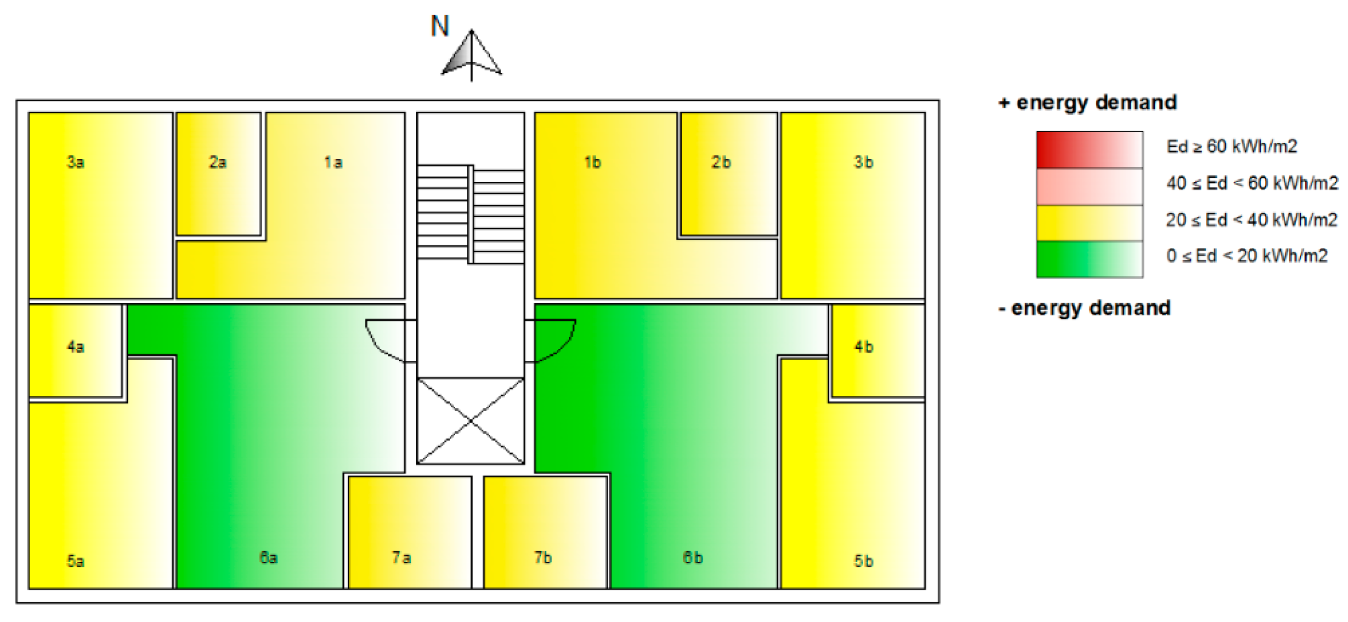
Bearing in mind the results of the energy assessment (Section 4.2), new infills are placed along the more dispersing façades, i.e., the north-, east-, and west-facing façades. Figure 8 displays the colour map relevant to the energy demand values deriving from the adopted thermal rehabilitation solution.
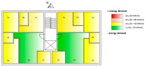
Figure 8.
Colour map of the energy demand (Ed) evaluated by replacing the external layer of infills with a new one having better thermal insulation properties.
As a result of the better thermal insulation, a large reduction of energy demand is found. The demand decreases to about 43 kWh/year for unit of area at each storey, compared to 74 kWh/year in the “as-built” configuration. Therefore, according to the performance classes given in [48], energy demand becomes consistent with the performance class D, while the as-built configuration was in class F.
Beyond better thermal insulation properties, cored bricks also have better mechanical properties compared to the hollow ones. Specifically, the compressive strength value relevant to the infill panels selected for thermal requirements is 4.0 MPa and the elastic modulus is 3300 Mpa. Therefore, the new infill walls are able to offer a larger resistance to the horizontal loads compared to those in the as-built configuration.
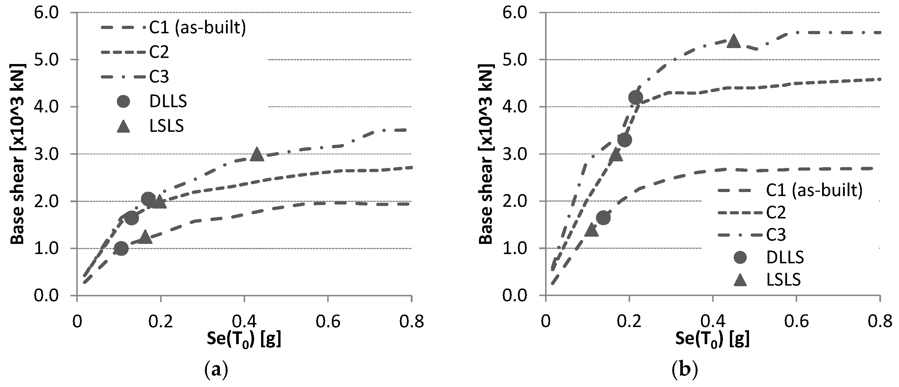
Figure 9 shows the seismic intensity (in terms of spectral pseudo-acceleration) vs. maximum base shear curves obtained for the new configuration C2 by considering median values in the two in-plane directions (X and Y direction).
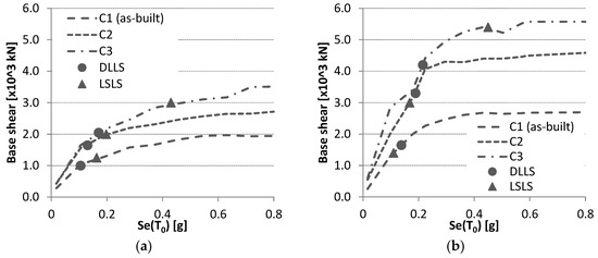
Figure 9.
Spectral pseudo-acceleration vs. maximum base shear curves relevant to the three considered configurations, obtained for X (a) and Y (b) direction by considering median values from IDA analyses.
C2 configuration is both stiffer and more resistant than the as-built configuration. In particular, the fundamental period reduces from 0.85 s to 0.65 s, while the maximum base shear value increases by 30% and 40% for X and Y direction, respectively. In terms of seismic performance, the seismic intensity values (in terms of spectral pseudo-acceleration values at the fundamental period of the structure) relevant to DLLS and LSLS increases of 24% (0.130 g) and 20% (0.197 g) in X direction, respectively. In the Y direction, the increment is equal to 37% (0.189 g) and 52% (0.168 g), respectively, for DLLS and LSLS. Table 4 reports the spectral intensity values relevant to the LSLS limit states (capacity, Se,C) and the hazard ones (demand, Se,D) evaluated for the same seismic levels previously defined (low-, mid-, and high-seismicity intensity). In the same table, the Se,C/Se,D ratio values (α) have been evaluated by considering the minimum value between X- and Y direction.

Table 4.
Comparison between seismic capacity values and hazard demand relevant to as-built and post-intervention configurations, evaluated for LSLS at different seismic intensity levels.
The new infill panels made up by replacing the external existing layer remarkably increase the post-intervention seismic capacity of the structure, thus determining α values higher than 1 for both Low and Mid seismic zone, while the intervention is not able to achieve a complete seismic rehabilitation for the highest seismic level considered.
In order to achieve a complete seismic rehabilitation even in High seismic zone, new RC frames have been added to the as-built configuration C1 (“double skin” solution, Figure 10) and effectively connected to the existing frames. The connection between the new and old structure, not detailed in this phase of the study, can be made up by adopting shear connectors with epoxy resin, properly designed also considering the mechanical properties of concrete in the existing structure.
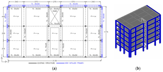
Figure 10.
C3 configuration: in plan layout of the retrofitted building (a) and 3D view of the model (b). External frames designed to have a significant contribution for the resistance to seismic loads are highlighted in blue.
New infilled frames have been designed to satisfy both thermal and seismic requirements. To this purpose, new infills have been primarily placed along the north, east, and west façades where the greater thermal losses have been found from the analyses (see Section 4.2). Starting from this configuration, new RC frames with new infills have been designed in order to increase also seismic capacity. Although the new infilled frames (as well as infill panels in C2 configuration) are arranged in a non-symmetric way along X direction, structural response to the horizontal actions is substantially regular. To this purpose, Table 5 shows the vibration period (T) and the participating mass (M%) values evaluated for both ante- and post- intervention configuration (C2 and C3) for X and Y direction. As a result of the participating mass values, in the different configurations the structure presents a regular response with translational displacements along the principal axis X and Y.

Table 5.
Period of vibration and participating mass values for each building configuration evaluated for X- and Y-direction.
Infill walls that are placed in new RC frames are the same adopted in C2 configuration (i.e., cored bricks 20 cm thick). Added to the existing infill panels, they are able to get an appropriate thermal insulation value (U = 0.29 W/m2K), i.e., lower than that prescribed for the considered climatic zone E (U = 0.30 W/m2K). In terms of energy demand, the same performance class (D) obtained for C2 configuration has been found for C3 configuration.
On the contrary, the addition of new frames significantly increases seismic performance. This result is clearly shown in Figure 9 where the IDA curves in terms of spectral pseudo-acceleration (corresponding to the fundamental period T = 0.60 s) and maximum base shear for each in-plane direction are displayed also for C3 configuration. In the same figure, the intensity values related to both Damage Limitation (DLLS) and Life Safety (LSLS) Limit State are also displayed. Specifically, intensity values for LSLS are equal to 0.430 g and 0.450 g for X and Y direction, respectively; for DLLS, intensity values are 0.170 g and 0.215 g for the X and Y direction, respectively. The values that are related to LSLS are also reported in Table 4 and compared to the related demand for the different seismic zones (intensity values evaluated at the fundamental period of the structure for TR = 475 y). As can be seen, in the case of C3 configuration, the seismic verification is always satisfied, with α equal to 1.38 in the high seismic zone.
5. Final Remarks
Promoting climate change adaptation, and, consequently, energy efficiency are key elements of the current and future policy worldwide. To achieve these goals it should be underlined, as stated in [75], that “the cleanest and most secure source of energy is the energy that is not used at all”.
The awareness that buildings are the largest single energy “consumer” in Europe, i.e., consuming 40% of final energy, prompted some European countries to start extensive requalification programs on the existing older building stock. Specifically, energy efficiency measures supported by public incentives have been carried out for a number of years.
At the same time, in some European countries, mainly in the framework of reconstruction/strengthening programs following damaging earthquakes, a great deal of seismic rehabilitation interventions have been carried out or are ongoing.
However, it is more and more evident that pursuing separately seismic and thermal rehabilitation is inappropriate, while there is a pressing demand to tackle simultaneously both the deficit of seismic protection, dramatically pointed out by past earthquakes, and the poor energy performance of the European buildings.
To this end, in the paper, after a short review of the Italian and European energy efficiency rules, an integrated approach in the design of interventions able to provide simultaneously thermal and seismic rehabilitation is proposed.
Emphasis is posed on the role of masonry infills that are widely used in Europe as enclosure walls in RC frame buildings. Their role in both thermal and seismic performance is discussed by dealing with a case study structure representative of RC existing buildings designed only to gravity loads. The selected structure has been analysed both as-built and after some possible rehabilitation interventions by means of Incremental Dynamic Analyses. Specifically, two rehabilitation solutions have been investigated .The first one is based on the replacement of the existing masonry infill walls with new elements able to ensure better thermal performances (C2 configuration), and the second one is based on the so-called “double skin” intervention technique (C3 configuration) where new RC infilled frames are added and structurally connected to the existing ones.
The existing infill walls have been partially replaced with new infills in order to satisfy the requirements in terms of energy saving. Further, the new infills, as they generally also have higher mechanical properties, are able to provide a greater lateral load resistance (about 50% higher than the as-built configuration in the considered building type). For mid-low hazard areas, this technique could determine a full rehabilitation with regards to both seismic and thermal requirements in compliance with the corresponding codes. Specifically, energy demand value decreases from 74 kWh/year per unit of area in C1 configuration to 43 kWh/year for unit area for C2 configuration. In terms of seismic performance, α value (ratio between the capacity and demand value) evaluated for mid-hazard area increases from 0.76 to 1.05, thus satisfying the safety verifications related to the Life Safety Limit State.
On the contrary, in case of high-hazard areas, the seismic deficit generally found in the considered building types requires strengthening interventions also on the RC structure or the addition of new RC resisting members. As for this latter solution, the “double skin” technique, which is made up of new infilled frames effectively connected to the existing RC frames, has been examined. Results show that it can be an effective and sustainable solution due to its ability to lead to an integrated seismic and thermal rehabilitation through interventions carried out from the outside, thus with reduced impairment of the inhabitants and building downtime. In particular, for the seismic performance, the considered intervention for C3 Configuration is able to increase the α value related to the Life Safety Limit State from 0.38 (as-built, C1configuration) to 1.38, thus largely satisfying the safety verifications.
Finally, it should be underlined that more studies need to be carried out on the interaction between stiffer infill panels and existing RC members. Particular attention needs to be devoted to beam-column joints whose performance could be critical as a consequence of the more demanding stress values due to the higher infill actions.
Acknowledgments
The work reported in this paper was carried out within the framework of the DPC-ReLUIS 2017 Project, Research Line “Reinforced Concrete Structures”, WP3—“Upgrading and Retrofitting of RC Existing Buildings”. Further, the authors wish to express their gratitude to the three anonymous reviewers for the comments and suggestions provided, which have been very helpful in improving this article.
Author Contributions
All the authors conceived the idea, developed the content and wrote the paper.
Conflicts of Interest
The authors declare no conflicts of interest.
References
- Ilki, A.; Fardis, M.N. (Eds.) Seismic Evaluation and Rehabilitation of Structures; Springer: Berlin/Heidelberg, Germany, 2014. [Google Scholar]
- Joint Research Center (JRC). New European Technical Rules for the Assessment and Retrofitting of Existing Structures; Dimova, S., Pinto, A., Luechinger, P., Denton, S., Eds.; Joint Research Center: Brussels, Belgium, 2015. [Google Scholar]
- CPR 305/2011/EU. Regulation (EU) No 305/2011 of the European Parliament and of the Council of 9 March 2011 laying down behavior conditions for the marketing of construction products and repealing Council Directive 89/106/EEC. Off. J. Eur. Union 2011, L 88, 5–43. [Google Scholar]
- CPD 89/106/CEE. Council Directive of 21 December 1988 on the approximation of laws, regulations and administrative provisions of the Member States relating to construction products. Off. J. Eur. Commun. 1989, L 40, 12–26. [Google Scholar]
- Buildings Performance Institute Europe (BPIE). Europe’s Buildings under the Microscope. A Country-by-Country Review of the Energy Performance of Buildings; Buildings Performance Institute Europe: Brussels, Belgium, 2011. [Google Scholar]
- Masi, A.; Manfredi, V.; Ventura, G. Progettazione integrata di interventi per il miglioramento delle prestazioni sismiche e termiche di edifici esistenti in c.a. In Proceedings of the ANIDIS Conference “L’ingegneria Sismica in Italia”, L’Aquila, Italy, 13–17 September 2015. (In Italian). [Google Scholar]
- ISTAT2011. 15° Censimento Generale Della Popolazione e delle Abitazioni. Available online: http://istat.it/MD/ (accessed on 20 February 2018). (In Italian).
- Rossetto, T.; Peiris, N.; Alarcon, J.E.; So, E.; Sargeant, S.; Free, M.; Sword-Daniels, V.; Del Re, D.; Libberton, C.; Verrucci, E.; et al. Field Observations from the Aquila, Italy Earthquake of April 6, 2009. Bull. Earthq. Eng. 2011, 9, 11–37. [Google Scholar] [CrossRef]
- Ricci, P.; De Luca, F.; Verderame, G.M. 6th April 2009 L’Aquila earthquake, Italy: Reinforced concrete building performance. Bull. Earthq. Eng. 2011, 9, 285–305. [Google Scholar] [CrossRef]
- Manfredi, G.; Prota, A.; Verderame, G.M.; De Luca, F.; Ricci, P. 2012 Emilia earthquake, Italy: Reinforced concrete buildings response. Bull. Earthq. Eng. 2014, 12, 2275–2298. [Google Scholar] [CrossRef]
- Penna, A.; Morandi, P.; Rota, M.; Manzini, C.F.; da Porto, F.; Magenes, G. Performance of masonry buildings during the Emilia 2012 earthquake. Bull. Earthq. Eng. 2014, 12, 2255–2273. [Google Scholar] [CrossRef]
- Masi, A.; Chiauzzi, L.; Santarsiero, G.; Liuzzi, M.; Tramutoli, V. Seismic damage recognition based on field survey and remote sensing: General remarks and examples from the 2016 Central Italy earthquake. Nat. Hazards 2017. [Google Scholar] [CrossRef]
- Law n. 10, 9 January 1991. Norme per L’attuazione del Piano Energetico Nazionale in Materia di uso Razionale Dell’energia, di Risparmio Energetico e di Sviluppo Delle Fonti Rinnovabili di Energia, n.13, 16–1-1991—Suppl. Ordinario n. 6.; Gazzetta Ufficiale: Rome, Italy, 1991. (In Italian)
- Fardis, M.N. Seismic Design, Assessment and Retrofitting of Concrete Buildings (Based on EN-Eurocode 8); Springer Science+Business Media BV: Dordrecht, The Netherlands, 2009; 766p, ISBN 978-1-4020-9841-3. [Google Scholar]
- Calvi, G.M. Choices and Criteria for Seismic Strengthening. J. Earthq. Eng. 2013, 17, 769–802. [Google Scholar] [CrossRef]
- Marino, F.P.R.; Grieco, M. La certificazione energetica degli edifici e il. D. Lgs 2009, 192, 720. (In Italian) [Google Scholar]
- Sassu, M.; Stochino, F.; Mistretta, F. Assessment method for Combined Structural and Energy Retrofitting in Masonry Buildings. Buildings 2017, 7, 71. [Google Scholar] [CrossRef]
- Mauro, G.M.; Menna, C.; Vitiello, U.; Asprone, D.; Ascione, F.; Bianco, N.; Prota, A.; Vanoli, G.P. A Multi-Step Approach to Assess the Lifecycle Economic Impact of Seismic Risk on Optimal Energy Retrofit. Sustainability 2017, 9, 989. [Google Scholar] [CrossRef]
- Calvi, G.M.; Sousa, L.; Ruggeri, C. Energy efficiency and seismic resilience: A common approach. In Multi-Hazard Approaches to Civil Infrastructure Engineering; Gardoni, P., LaFave, J.M., Eds.; Springer International Publishing: Cham, Switzerland, 2016. [Google Scholar]
- Marques, R.; Lamego, P.; Lourenço, P.B.; Sousa, M.L. Efficiency and Cost-Benefit Analysis of Seismic Strengthening Techniques for Old Residential Buildings in Lisbon. J. Earthq. Eng. 2017. [Google Scholar] [CrossRef]
- Fardis, M.N. Design provisions for masonry-infilled RC frames. In Proceedings of the 12th World Conference on Earthquake Engineering, Auckland, New Zeland, 30 January–4 February 2000. [Google Scholar]
- Dolšek, M.; Fajfar, P. Soft storey effects in uniformly infilled reinforced concrete frames. J. Earthq. Eng. 2001, 5, 1–12. [Google Scholar] [CrossRef]
- Masi, A.; Digrisolo, A.; Manfredi, V. Fragility curves of gravity-load designed RC buildings with regularity in plan. Earthq. Struct. 2015, 9, 1–27. [Google Scholar] [CrossRef]
- Manfredi, V.; Masi, A. Consistency of analysis methods considered in EC8-3 for the seismic assessment of RC existing buildings. Bull. Earthq. Eng. 2017. [Google Scholar] [CrossRef]
- Fardis, M.N.; Panagiotakos, T.B. Seismic design and response of bare and masonry-infilled reinforced concrete buildings. Part II: Infilled structures. J. Earthq. Eng. 1997, 1, 475–503. [Google Scholar] [CrossRef]
- Masi, A. Seismic vulnerability assessment of gravity load designed R/C frames. Bull. Earthq. Eng. 2003, 1, 371–395. [Google Scholar] [CrossRef]
- Repapis, C.; Zeris, C.; Vintzileou, E. Evaluation of the seismic performance of existing RC buildings: II. A case study for regular and irregular buildings. J. Earthq. Eng. 2006, 10, 429–452. [Google Scholar] [CrossRef]
- Verderame, G.M.; De Luca, F.; Ricci, P.; Manfredi, G. Preliminary analysis of a soft-storey mechanism after the 2009 L’Aquila earthquake. Earthq. Eng. Struct. Dyn. 2011, 40, 925–944. [Google Scholar] [CrossRef]
- Braga, F.; Manfredi, V.; Masi, A.; Salvatori, A.; Vona, M. Performance of nonstructural elements in RC buildings during the L’Aquila, 2009 earthquake. Bull. Earthq. Eng. 2011, 9, 307–324. [Google Scholar] [CrossRef]
- Manfredi, V.; Masi, A. Combining in-plane and out-of-plane behavior of masonry infills in the seismic analysis of RC buildings. Earthq. Struct. 2014, 6, 457–472. [Google Scholar] [CrossRef]
- Calvi, G.M.; Bolognini, D.; Penna, A. Seismic performance of masonry-infilled r.c. frames: Benefits of slight reinforcement. In Proceedings of the Sismica 2004—6° Congresso Nacional de Sismologia e Engenharia Sísmica, Guimarães, Portugal, 14–16 April 2004. [Google Scholar]
- Guidi, G.; da Porto, F.; Dalla Benetta, M.; Verlato, N.; Modena, C. Comportamento sperimentale nel piano e fuori dal piano di tamponamenti in muratura armata e rinforzata. In Proceedings of the ANIDIS Conference “L’ingegneria Sismica in Italia”, Padova, Italy, 30 June–4 July 2013. (In Italian). [Google Scholar]
- Preti, M.; Migliorati, L.; Giuriani, E. Experimental testing of engineered masonry infill walls for post-earthquake structural damage control. Bull. Earthq. Eng. 2015, 13, 2029. [Google Scholar] [CrossRef]
- Da Porto, F.; Verlato, N.; Guidi, G.; Modena, C. The INSYSME project: Innovative construction systems for earthquake resistant masonry infill walls. In Brick and Block Masonry—Trends, Innovations and Challenges; Modena, C., da Porto, F., Valluzzi, M.R., Eds.; Taylor & Francis Group: London, UK, 2016; ISBN 978-1-138-02999-6. [Google Scholar]
- Morandi, P.; Milanesi, R.R.; Magenes, G. Innovative seismic solution for clay masonry infills with sliding joints: Principles and details. In Brick and Block Masonry—Trends, Innovations and Challenges; Modena, C., da Porto, F., Valluzzi, M.R., Eds.; Taylor & Francis Group: London, UK, 2016; ISBN 978-1-138-02999-6. [Google Scholar]
- Fiore, A.; Mezzina, M.; Porco, F.; Uva, G. Solidarizzazione delle tamponature per il miglioramento sismico di edifici esistenti. In Proceedings of the ANIDIS Conference “L’ingegneria sismica in Italia”, Padova, Italy, 30 June–4 July 2013. (In Italian). [Google Scholar]
- Vamvatsikos, D.; Cornell, C.A. Incremental dynamic analysis. Earthq. Eng. Struct. Dyn. 2002, 31, 491–514. [Google Scholar] [CrossRef]
- Marini, A.; Feroldi, F.; Belleri, A.; Passoni, C.; Preti, M.; Giuriani, E.; Riva, P.; Plizzari, G. Coupling energy refurbishment with structural strengthening in retrofit interventions. In Proceedings of the SAFESUST Workshop, Ispra, Italy, 26–27 November 2015. [Google Scholar]
- Law n. 373, 30 March 1976. Norme per il Contenimento del Consumo Energetico per usi Termici Negli Edifici, n.148; Gazzetta Ufficiale: Rome, Italy, 1976. (In Italian)
- Presidential Decree n. 412, 26 August 1993. Regolamento Recante Norme per la Progettazione, L’installazione, L’esercizio e la Manutenzione Degli Impianti Termici Degli Edifici ai Fini del Contenimento dei Consumi di Energia, in Attuazione dell’art. 4, Comma 4, della Legge 9 gennaio 1991, n. 10, n.242, 14-10-1993–S.O. n. 96; Gazzetta Ufficiale: Rome, Italy, 1993. (In Italian)
- Directive 2002/91/EC of the European Parliament and of the Council of 16 December 2002 on the energy performance of buildings. Off. J. Eur. Commun. 2003, L 1, 65–71.
- Kyoto Protocol to the United Nations Framework Convention on Climate Change. United Nations, 1998. Available online: http://unfccc.int/ (accessed on 20 February 2018).
- Legislative Decree n. 192, 19 August 2005. Attuazione della Direttiva 2002/91/CE Relativa al Rendimento Energetico Nell’edilizia, n. 222, 23-9-2005—Suppl. Ordinario n. 158; Gazzetta Ufficiale: Rome, Italy, 2005. (In Italian)
- Legislative Decree n. 311, 29 December 2006. Disposizioni Correttive ed Integrative al Decreto Legislativo n. 192 del 2005, Recante Attuazione Della Direttiva 2002/91/CE, Relativa al Rendimento Energetico Nell’edilizia, n. 26; Gazzetta Ufficiale: Rome, Italy, 2007. (In Italian)
- Presidential Decree n. 59, 2 Aprile 2009. Regolamento di Attuazione Dell’articolo 4, Comma 1, Lettere a) e b), del Decreto Legislativo 19 Agosto 2005, n. 192, Concernente Attuazione Della Direttiva 2002/91/CE sul Rendimento Energetico in Edilizia, n. 132; Gazzetta Ufficiale: Rome, Italy, 2009. (In Italian)
- Directive 2010/31/EU of the European Parliament and of the Council of 19 May 2010 on the energy performance of buildings. Off. J. Eur. Union 2010, L 153, 13–35.
- Legislative Decree n. 28, 3 March 2011. Attuazione Della Direttiva 2009/28/CE Sulla Promozione Dell’uso Dell’energia da Fonti Rinnovabili, Recante Modifica e Successiva Abrogazione Delle Direttive 2001/77/CE e 2003/30/CE, n.71 del 28-3-2011—Suppl. Ordinario n. 81; Gazzetta Ufficiale: Rome, Italy, 2011. (In Italian)
- Ministerial Decree 26 June 2015. Applicazione Delle Metodologie di Calcolo Delle Prestazioni Energetiche e Definizione Delle Prescrizioni e dei Requisiti Minimi Degli Edifici, n. 162, 15-07-2015—Suppl. Ordinario n. 39; Gazzetta Ufficiale: Rome, Italy, 2015.
- Masi, A.; Manfredi, V.; Vona, M.; Braga, F.; Salvatori, A. Prestazioni degli elementi non strutturali negli edifici in c.a.: Implicazioni progettuali e costruttive alla luce dell’esperienza del terremoto dell’Abruzzo 2009. Progett. Sismica 2010, 51–66. (In Italian) [Google Scholar]
- Lamego, P.; Lourenço, P.B.; Sousa, M.L. Marques, R. Seismic vulnerability and risk analysis of the old building stock at urban scale: Application to a neighbourhood in Lisbon. Bull. Earthq. Eng. 2017, 15, 2901–2937. [Google Scholar] [CrossRef]
- De Sortis, A.; Bazzurro, P.; Mollaioli, F.; Bruno, S. Influenza delle tamponature sul rischio sismico degli edifici in calcestruzzo armato. In Proceedings of the ANIDIS Conference “L’ingegneria Sismica in Italia”, Pisa, Italy, 10–14 June 2007. (In Italian). [Google Scholar]
- Campioli, A.; Ferrari, S.; Lavagna, M. Il D.Lgs 192/2005 e le chiusure verticali opache. Come si cambia. Costruire 2006, 277, 1–7. (In Italian) [Google Scholar]
- Biondi, S.; Colangelo, F.; Nuti, C. La Risposta Sismica dei Telai con Tamponature Murarie; CNR-Gruppo Nazionale per la Difesa dai Terremoti: Roma, Italy, 2000; p. 179. (In Italian) [Google Scholar]
- Colangelo, F. Stima della resistenza a compressione delle tamponature. Costruire Laterizio 2004, 17, 62–67. (In Italian) [Google Scholar]
- Beconcini, M.L. Resistenza a Forze Orizzontali di Pareti in Elementi Forati di Laterizio. Research Report. 2004. Available online: www.laterizio.it (accessed on 20 February 2018). (In Italian).
- Campioli, A.; Ferrari, S.; Lavagna, M.; Monticelli, C.; Morello, E. Involucri in laterizio. Ricette di chiusura. Costruire 2006, 281, 165–180. (In Italian) [Google Scholar]
- Albanesi, T.; Bergami, A.V.; Nuti, C.; Biondi, S.; Candigliota, E. Caratterizzazione teorico-sperimentale di tamponature in laterizio per telai in cemento armato. In Proceedings of the ANIDIS Conference “L’ingegneria sismica in Italia”, Pisa, Italy, 10–14 June 2007. (In Italian). [Google Scholar]
- Circular n. 617, 2 February 2009. Istruzioni per L’applicazione Delle “Nuove Norme Tecniche per le Costruzioni” di cui al D.M. 14 Gennaio 2008. Ministero delle Infrastrutture e dei Trasporti, n. 47, 26 February 2009, Supplemento Ordinario n. 27; Gazzetta Ufficiale: Rome, Italy, 2009. (In Italian)
- Monticelli, C. Il comportamento energetico di pareti in laterizio a vista. Costru. Laterizio 2009, 127, 54–61. (In Italian) [Google Scholar]
- Ministrial Decree 14 January 2008, NTC 2008. Norme Tecniche per le Costruzioni, Ministero delle Infrastrutture. Available online: http//www.cslp.it (accessed on 20 February 2018). (In Italian).
- McKenna, F. OpenSees: A framework for earthquake engineering simulation. Comput. Sci. Eng. 2011, 13, 58–66. [Google Scholar] [CrossRef]
- Ibarra, L.F.; Medina, R.A.; Krawinkler, H. Hysteretic models that incorporate strength and stiffness deterioration. Earthq. Eng. Struct. Dyn. 2005, 34, 1489–1511. [Google Scholar] [CrossRef]
- Haselton, C.B.; Deierlein, G.G. Assessing Seismic Collapse Safety of Modern Reinforced Concrete Moment Frame Buildings; Blume Report n. 156; Department of Civil and Environmental Engineering, Stanford University: Standford, CA, USA, 2007. [Google Scholar]
- Sezen, H. Seismic Response and Modeling of Reinforced Concrete Building Columns. Ph.D. Thesis, Department of Civil and Environmental Engineering, University of California, Berkeley, CA, USA, 2002. [Google Scholar]
- Elwood, K.J.; Moehle, J.P. Dynamic collapse analysis for a reinforced concrete frame sustaining shear and axial failures. Earthq. Engng. Struct. Dyn. 2008, 37, 991–1012. [Google Scholar] [CrossRef]
- Bertoldi, S.H.; Decanini, L.D.; Gavarini, C. Telai tamponati soggetti ad azioni sismiche, un modello semplificato, confronto sperimentale e numerico. In Proceedings of the VI ANIDIS Conference “L’ingegneria sismica in Italia”, Perugia, Italy, 13–15 October 1993. (In Italian). [Google Scholar]
- Masi, A.; Manfredi, V.; Cetraro, G. In-plane performance of RC infilled frames under seismic actions: Experimental versus code provision values. In Brick and Block Masonry—Trends, Innovations and Challenges; Modena, C., da Porto, F., Valluzzi, M.R., Eds.; Taylor & Francis Group: London, UK, 2016; ISBN 978-1-138-02999-6. [Google Scholar]
- Decanini, L.; Liberatore, L.; Mollaioli, F. Strength and stiffness reduction factors for infilled frames with openings. Earthq. Eng. Eng. Vib. 2014, 13, 437–454. [Google Scholar] [CrossRef]
- UNI/TS 11300-1. Prestazioni Energetiche Degli Edifici Parte 1: Determinazione del Fabbisogno di Energia Termica Dell’edificio per la Climatizzazione Estiva ed Invernale; Ente Italiano di Normazione: Milano, Italia, 2014. (In Italian) [Google Scholar]
- Acca Software S.p.A. Thermus. Prestazioni energetiche e Certificazione. Available online: www.acca.it (accessed on 20 February 2018).
- Iervolino, I.; Spillatura, A.; Bazzurro, P. RINTC project: Assessing the (implicit) seismic risk of code-conforming structures in Italy. In Proceedings of the COMPDYN 2017, 6th ECCOMAS Thematic Conference on Computational Methods in Structural Dynamics and Earthquake Engineering, Rhodes Island, Greece, 15–17 June 2017; Papadrakakis, M., Fragiadakis, M., Eds.; National Technical University of Athens: Athens, Greece, 2017. [Google Scholar]
- Camata, G.; Celano, F.; De Risi, M.T.; Franchin, P.; Magliulo, G.; Manfredi, V.; Masi, A.; Mollaioli, F.; Noto, F.; Ricci, P.; et al. RINTC project: Nonlinear Dynamic Analyses of Italian code-conforming Reinforced Concrete Buildings for Risk of Collapse Assessment. In Proceedings of the COMPDYN 2017—6th ECCOMAS Thematic Conference on Computational Methods in Structural Dynamics and Earthquake Engineering, Rhodes Island, Greece, 15–17 June 2017; Papadrakakis, M., Fragiadakis, M., Eds.; National Technical University of Athens: Athens, Greece, 2017. [Google Scholar]
- Masi, A.; Santarsiero, G.; Nigro, D. Cyclic tests on external RC beam-column joints: Role of seismic design level and axial load value on the ultimate capacity. J. Earthq. Eng. 2013, 17, 110–136. [Google Scholar] [CrossRef]
- Presidential Decree n. 3519/2006. Criteri Generali Per L’individuazione Delle Zone Sismiche e Per la Formazione e L’aggiornamento Degli Elenchi Delle Medesime Zone, n. 108; Gazzetta Ufficiale: Rome, Italy, 2006. (In Italian)
- European Commission. Proposal for a Directive of the European Parliament and of the Council Amending Directive 2012/27/EU on Energy Efficiency; European Commission: Brussels, Belgium, 2016. [Google Scholar]
© 2018 by the authors. Licensee MDPI, Basel, Switzerland. This article is an open access article distributed under the terms and conditions of the Creative Commons Attribution (CC BY) license (http://creativecommons.org/licenses/by/4.0/).

