Article

Durability of Stone Cladding in Buildings: A Case Study of Marble Slabs Affected by Bowing

CONSTRUCT, Faculty of Engineering, University of Porto, 4200-465 Porto, Portugal
*
Author to whom correspondence should be addressed.
Buildings 2019, 9(11), 229; https://doi.org/10.3390/buildings9110229
Submission received: 16 July 2019 / Revised: 24 October 2019 / Accepted: 25 October 2019 / Published: 1 November 2019

Abstract

:
Bowing is an uncommon pathology that can affect marble stone cladding of building façades, causing a large permanent deflection and the degradation of the flexural and anchoring strength of the stone slabs, which can lead to the cladding falling from the façades. Moreover, the combination of bowing with wind pressure effects on the building façades can increase the risk of fracture and collapse of the stone slabs, especially if this combination is not properly evaluated during design. Motivated by a case study, this work describes a stability evaluation of a 15-year-old building façade coated with marble stone cladding affected by bowing and subjected to wind pressures. This evaluation was focused on the stone slabs, and was performed through finite element model (FEM) numerical simulations of these slabs submitted to wind pressures and through lab tests using samples of stone slabs removed from the building façade. The results obtained demonstrated stability problems on the stone slabs caused by wind pressure-induced stresses combined with the loss of strength due to aging and bowing effects, especially for slabs with larger dimensions.

1. Introduction

In the 20th century, given the surge of urban construction, industrial development, and the capacity of new equipment to cut stone in thinner slices/slabs pushed the use of stone to comprise ventilated cladding façades, i.e., with an air space/cavity behind the stone slabs. Moreover, intermediate metallic anchoring systems were developed in order to form the air cavity while supporting the slabs (e.g., systems based on metallic pin dowels or kerfs fixed directly to the building or fixed indirectly by a secondary structure). This solution has the advantage of reducing weight and cost due to the lower thickness of slabs (typically between 20 mm and 50 mm) while giving a sense of nobility and durability associated to existing ancient stone constructions, thus becoming quite popular in use on façades at the end of the last century.
Even though most of ventilated claddings façades perform reasonably, some anomalies appeared over the last few decades, such as deterioration of appearance, fracture, arching and falling of stone slabs, therefore causing durability and security problems [1]. According to inspections performed on several buildings with natural stone cladding façades, these problems seem more related to design and execution errors and environmental actions [2]. One of the most uncommon anomalies is the bowing of marble slabs, which is characterized by a permanent large deflection accompanied strength decay of the slabs, causing them to fall from the façades [1,3,4].
The bowing phenomena has been reported mainly on marble ventilated cladding, causing the fall of the stone slabs usually followed by its total removal from the façades, sometimes just after a few years of construction. In some cases, permanent deflections of 20 to 30 mm/m and a strength decay of more than 40% in the stone slabs were reported (flexural strength and breaking load at the fixing points of the slab) [1,3,4]. Some well-known building façades made with marble claddings were affected by bowing and the total replacement of the cladding was needed, such as the “Amoco building” (Chicago, USA), the “Finlandia Hall” (Helsinki, Filand) or the “Grande Arche de la Defense” (Paris, France) [3,4]. In the case of the “Amoco building” the replacement of all marble panels required a costly intervention ($65 million dollars) [4]. However, bowing seems not to be a recent anomaly or even directly related to the use of thinner slabs, since bowing was reported from ancient gravestones made of marble slabs 8 to 9 cm in thickness [5].
The main causes of bowing are complex are still under discussion in the scientific community, since it seems to be associated to more than one cause. Regardless, the most cited causes for bowing seem more related to the intrinsic nature of calcite marbles, which can be aggravated by some technical implementation aspects of the stone cladding in the façades. As for the intrinsic nature of calcite marbles, the anisotropic deformation of calcite crystals associated with their thermal expansion and contractions, in a process called thermal hysteresis, causes residual strain release and irreversible expansion of the stone matrix, resulting in large deformation/bowing and strength decay of the slabs [6,7]. Specific studies report the bowing of marble slabs as the result of combining excessive temperature drying and moisture/damping cycles with the use of calcite marbles with weak interlocking between the calcite crystals [3,5]. This causes an irreversible expansion and an inter-granular de-cohesion of the stone matrix, thus generating the bowing effect accompanied by weakening in strength of the stone slabs [3,5]. Moreover, according to some experimental results [4], the orientation of the stone cut relatively to the sedimentation process seems to be an important aspect, since the bowing intensity depends on the orientation of the marble stratification planes. As for the technical implementation of the stone cladding, some aspects can enable the slabs in compression, thus aggravating the bowing effects. The narrowness of joints between slabs and fixing systems restraining the stone expansion, the excessive flexibility of the anchoring system, and the insufficient strength of the stone slabs at their fixing points, are aspects that can hinder the thermal expansion and relaxation of internal stresses [6,7]. Moreover, according to some monitoring results of bowing obtained from several ventilated marble claddings (“Carrara” and other similar calcite marbles) mounted on existing public buildings aged between 9 and 15 years [4], additional relevant factors are the solar radiation exposure, the stone moisture content and the location of the stone slabs in the façades. The bowing deflection magnitude seems to be higher in corners and at the tops of the façades, and varies with the intensity of solar orientation of the façades and with the moisture content of the stones slabs during their heating/drying process. Moreover, the bowing magnitude varied between 3 to 12 mm/m and the marble presented 40% to 60% of strength decay (flexure strength and breaking load at dowel whole) [4]. Considering the evolution of bowing effects, some studies performed on marble slabs report that bowing deflection is irreversible, the magnitude increases and causes the loss/degradation of the stone mechanical strength over time, usually faster in the beginning and slower over time [5,8].
As mentioned before, bowing seems more frequent in marble cladding; therefore, it is important to know some properties of this type stone. According to scientific and technical literature [6,9,10,11,12,13], the marble can be characterized as a metamorphic stone consisting essentially of calcite crystals (94% to 99%), or more rarely of dolomite crystals, and may contain other minerals in smaller quantities (mica, quartz, dolomite, graphite, among others). Most calcite marbles are white or approximately white and may have veins given by the presence of other minerals (mentioned above). Some of the most well-known marbles are “Carrara (Italy)”, “Estremoz (Portugal)”, “Vermont (USA)”, “Dionysos (Greece)”, among others. Since it is a natural material, its physical and mechanical properties can vary significantly (more than 20% of the average), even when extracted from the same quarry. Therefore, it is necessary to characterize their properties experimentally on a case-by-case basis. However, some mean values for the properties of white calcite marbles under initial conditions of use (such as “Carrara”, “Évora/Estremoz”, among others) can be found in literature [6,9,10,11,12,13]:
  • Density: 2680 to 2710 (kg/m3);
  • Compressive strength: 79 to 100 (×106 Pa);
  • Flexural strength/Modulus of rupture: 9 to 26 (×106 Pa);
  • Elasticity modulus (dynamic/static): 40 to 50/16 to 25 (×109 Pa);
  • Poisson coefficient: 0.25 to 0.41.
The occurrence of anomalies related to bowing in marble slabs suggest that there is a need to control the effects or to predict the tendency of bowing in real on-site cladding applications. This seems possible according to experimental investigations and the recently published European standard test method. According to comparative studies using data obtained from investigations of bowing in building façades and from bowing tests performed on calcite marbles involving heat and humidification cycles, the performed tests were able to simulate the bowing behavior tendency/trend under real conditions [4,5]. The evolution of bowing, relationship between strength decay and bowing increase and the behavior of bowing due to different stone-cutting directions were satisfactorily reproduced. However, additional investigation was also recommended in order to allow a more accurate extrapolation of laboratory results to the building façades [5].
Nevertheless, the bowing phenomenon has been studied in European projects on marble durability since 1999, followed by the publication of an European standard test method in 2013 [14,15]. The standard EN 16,306 [16] defines a durability/aging test method to characterize the bowing behavior of marbles subjected to 50 heat/humidity cycles (each with an duration of 24 h, including 7 h of temperature/humidity exposure from 20 to 80 °C, cooling to 20 °C and bowing measurement), establishing allowable limits for bowing (≤0.4 mm/m). Moreover, the experimental characterization of the elasticity modulus and the flexural strength after aging tests are defined for the design of marble slabs, since it is known that the rapid loss of strength and rigidity in the marbles are affected by bowing [16]. However, recent studies or technical documents involving the use of this test method in marble stone claddings are not easily found in literature, which may be explained by the relatively recent publication of EN 16,303 [16] and/or some lack of recognition by the manufacturers given the uncommon characteristic of the bowing phenomena.
On the other hand, the wind pressure effects on the façades may increase the risk of stability problems on stone cladding in use affected by bowing, especially if not properly evaluated during the cladding design. Wind pressure effects on façades can be estimated through standard calculation methodologies (e.g., Eurocode 1 [17]) and general design procedures and construction provisions for stone claddings are available in some technical literature and practice manuals (e.g., [18,19,20,21,22]). Some of these manuals recognizes the bowing of marble slabs [19,22], despite of only indicating a reference study concerning the discussion of thermal hysteresis, which includes some test data and thickness recommendations for “Carrara” marbles [6]. Other technical literature defines some reference design limits for ventilated stone cladding fixed with pin-dowel systems, however without mentioning any aspects related to bowing [18,20]. Nevertheless, some of these reference design limits seem important for a suitable application of the stone cladding. For example, the maximum allowable height of application in buildings (≤28 m), minimum thickness (≥27 mm) and maximum dimensions for the slabs (wind exposed area ≤1 m2; longer side ≤ 1.4 m; long to short side ratio ≤l), recommended number of fixing points (4), minimum joint thickness between slabs (≥6 mm) and between slabs and fixing systems (≥3 mm), among others aspects. Moreover, higher limits for the dimensions of the slabs are permitted to be used, if properly justified by testing or/and design methods [20].
The main aspects defined in literature for the design of stone slabs affected by wind effects are the flexural strength and the load/anchorage resistance of the slabs fixings, the latter being the critical factor, especially for dowel-hole anchorage systems, since it causes a high concentration of stresses near the stone-fixing points [18,23]. Empirical design formulas based on geometrical/mechanical characteristics of the stone slabs and fixing/anchorage systems are available [18,23]. Moreover, the evaluation of the wind stability/safety assessment methodology is also defined for stone cladding using serviceability/ultimate limit sates methodology and partial safety factors, which are defined according to the coefficient of variation of stone properties [18,24,25]. In addition, the design of stone slabs should also include numerical simulations in order to evaluate the stress levels induced by the wind action/pressure. These simulations can be performed through simplified or complex models. The use of complex models are based on a finite element model (FEM) and can be used for more detailed/accurate analyses, such as for studying the behavior of the claddings fixing systems using contact models [26,27]. FEMs employing the theory of thin plates could also be used in general static analysis of stone slabs [24], especially when the slabs have unusual shapes and/or support/fixing conditions that could affect the internal stress distribution [18]. However, the applicability of numerical simulations with FEM may become limited for stones with high heterogeneity [26,28] (e.g., slates), especially when using contact or non-linear elastoplastic models for brittle/quasi-britle materials, since the majority of existing models were developed assuming isotropic materials (e.g., [29]). In the case of materials with lower heterogeneity, these elastoplastic models can be applied with success for brittle/quasi-britle materials with similar mechanical behavior to stone (e.g., concrete [29,30] and masonry [31,32]). These models usually include the use of stress-strain data obtained from direct compressive or tensile lab tests in order to perform accurate calibrations [29,30,31,32]. Nevertheless, when using limit states analysis according to standard design calculation methodologies, it is usually assumed that brittle/quasi-brittle materials (e.g., concrete, masonry, wood) are homogenous/isotropic and have a linear elastic behavior until failure, either using undamaged elasticity for all levels of stress/loading or using a damaged elasticity for higher stress/loading levels. As suggested by some design manuals and scientific literature [18,24], the design based on limit states analysis can be applied for stone cladding ventilated façades. Therefore, a safer although conservative design is expected given the high values normally used for the safety factors of actions (e.g., 1.5 for win pressures [33]) and strength properties (e.g., 1.5 to 3.8 for stone, depending on the variation coefficients of the stone properties, ranging from 10% to 30% [18]).
The wind design of stone cladding can be assisted by testing through performing standard laboratory tests with small stone specimens (e.g., EN 1469 [34]) to determine some mechanical proprieties (e.g., flexural strength, elasticity modulus and the fixing/load resistance at dowel hole). Moreover, an alternative test method could be also performed which allows a more global evaluation of wall cladding kits mechanically fixed [35]. This test step-up involves the use of large modular specimens of the complete cladding system (several slabs, their fixing system and joints), which are mounted in a relatively airtight test chamber and submitted to several levels of air pressure until permanent damage or failure in the cladding system occurs [34]. This testing methodology allows simulating the behavior of the cladding systems summited to wind pressure effects in a closer way to their real on-site installation conditions.
According to the review previously undertaken, wind design procedures and standard bowing test procedures are available for ventilated stone cladding, including some scientific studies regarding the possible causes, effects and influencing factors of bowing in marble ventilated claddings. However, studies or design methodologies regarding the stability evaluation of ventilated marble cladding affected simultaneously by wind effects and bowing are rare/not easily found in scientific or technical literature, for either new or existing claddings. Therefore, this article aims to make a contribution regarding the stability evaluation and safety implications for existing ventilated stone claddings affected by bowing and wind pressures. To that end, a 15-year-old existing building having a ventilated marble cladding affected by bowing and wind pressures was used as a case study. An evaluation of the mechanical resistance and stability of the marble slabs, including their fixing points, was performed through available standard design procedures assisted by lab test results obtained from stone samples removed from the building façade, including the use of a FEM calibrated and simplified model to simulate the stone slabs summited to wind pressures.

2. Marble Slabs Affected by Bowing and Wind Pressure—A Case Study

2.1. Construction Aspects of the Stone Cladding

The building is located near the sea coast of Porto City in Portugal and its use is mainly for housing. It has an approximately regular volumetric shape, 18 m tall and plan dimensions of 16 × 36 m2. The façades of the building did not have significant protection provided by other surrounding buildings, except for the south- and west-orientated façades, which have some protection provided by nearby buildings and trees (10 m height located about 3 m apart from the building).
All the façades are covered by marble ventilated cladding (about 1000 m2 of cover area); however, the west façade is the less covered façade since it has about 80% of glazing. The cladding system is made of marble stone slabs with 5 mm thick open joints and are fixed to building façades with an air layer/cavity, forming a “ventilated façade” (Figure 1). The most representative stone slabs have surface dimensions that range from 1.5 × 1.3 m2 to 1.5 × 0.7 m2, and all the slabs have a thickness of 3 cm. These slabs are fixed to the building façade through a stainless steel dowel anchorage system (body anchorage fixed on the walls, having pin dowels inserted in holes made on the slabs), and each slab has four fixing points (Figure 2).

2.2. Bowing of the Marble Cladding

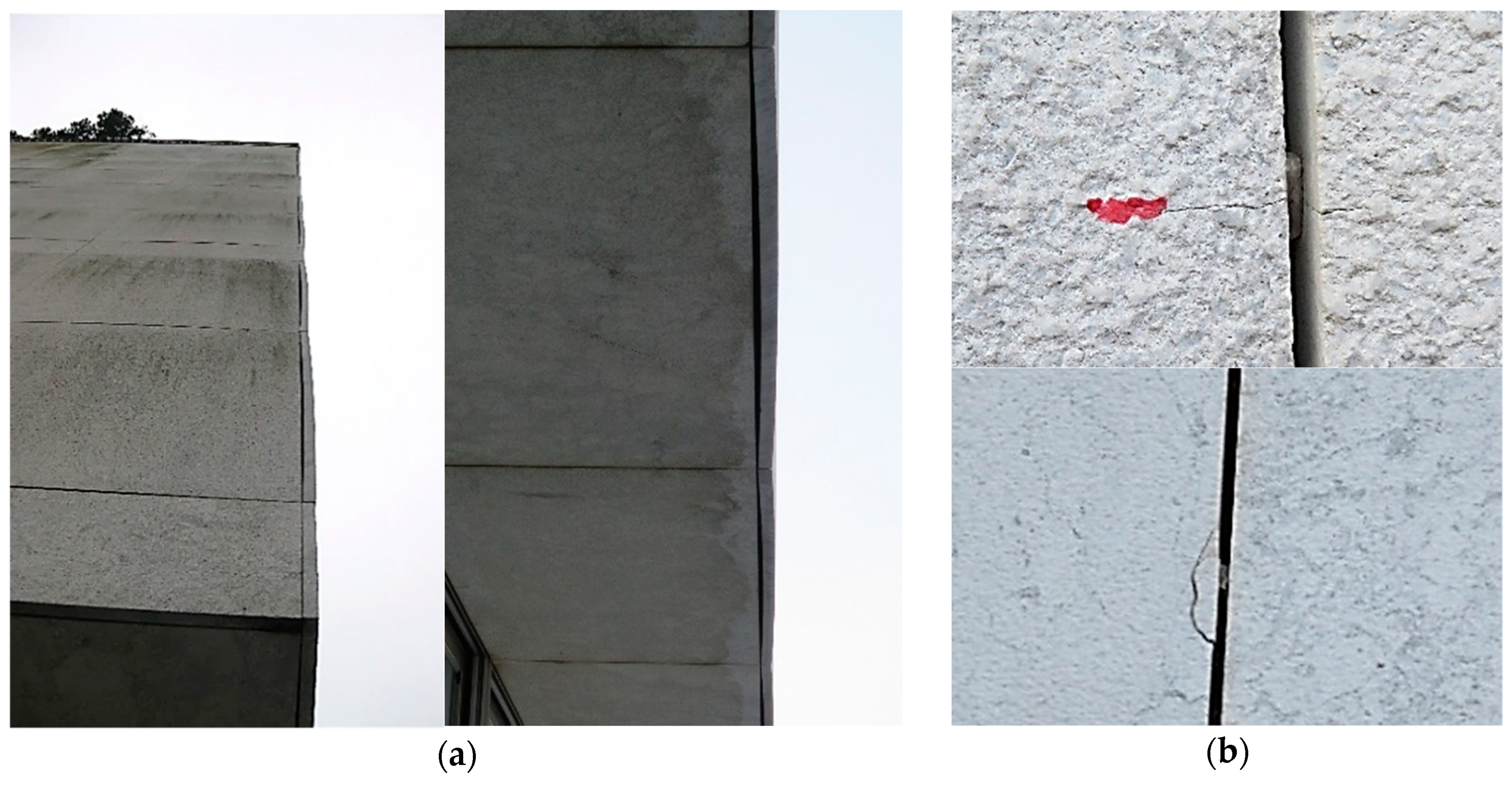
According to visual inspections and some measurements performed on the building façade, the bowing was affecting more than 50% of all the cladding applied on the façades, being more severe in the east and west façades and partially on the south façade. In general, the bowing occurs in all the height and width of these façades, except in 8 m of width of the north façade and in the first 10 m of height of the south façade. This may be related to the lower sun radiation exposure of the north façade and to the solar protection provided by nearby buildings and trees in the south façade. The bowing magnitude was higher in the slabs mounted near the vertical and horizontal corners, and on the top of the façades. In these places, permanent deflections of 8 to 12 mm (or 6 to 7 mm/m) were measured. No damage/fracture patterns were detected in the central part of the slabs with bowing; however, small fracture patterns were found near the fixing points (dowel holes) of some slabs affected by bowing (about 15%) (Figure 3).

2.3. Experimental Tests

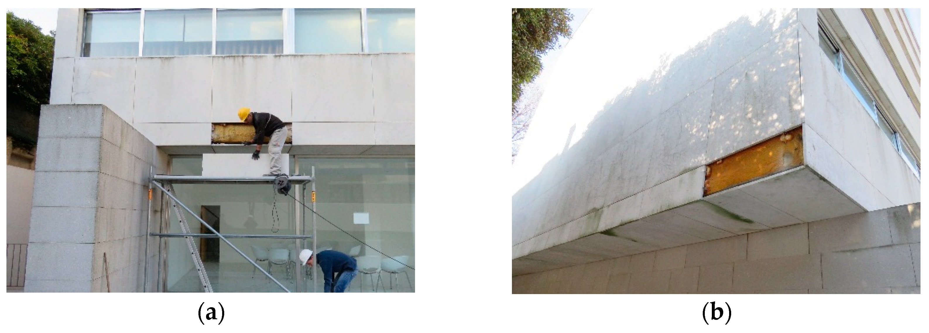
In order to characterize mechanical properties of the marble slabs under current conditions of use (i.e., flexural/bending strength, compressive strength breaking load at dowel hole and modulus of elasticity), test specimens were obtained from slabs removed from the building façade. It was possible to remove only four slabs due to restrictions imposed by the building owners, i.e., two slabs with bowing and two slabs without bowing. The slabs with bowing were removed from the east façade and the ones without bowing were removed from the south side (Figure 4). These slabs were located 3 m high and were mounted near the corner of the building, having dimensions of 1.46 m × 0.42 m × 0.03 m (length × width × thickness). Apart from the bowing, all slabs where selected without any visible damage (deterioration or fracture). The slabs with bowing presented permanent deflection magnitude of 10 mm (5 mm/m) in average. On the other hand, previous test results or test samples of marble slabs in initial conditions of use (i.e., unaffected by aging/deterioration agents) were not available for this study.
The tests were performed according to the set-up conditions available in the laboratory, following the test principles defined in European standards for natural stone. The dimensions and number of test specimens used in the lab tests were limited by the dimensions and by the available quantity of the stone slabs removed from the building façade (four samples as mentioned before). The test specimens were cut out from the slabs according to the position represented in Figure 5 in order to obtain the mechanical proprieties in the parallel direction of the marble stratification plane (i.e., flexural, modulus of elasticity and compressive test specimens).
The flexural/bending strength (σ) under constant moment and the static modulus of elasticity in the longitudinal direction (EsL) were determined using experimental data obtained from tests performed according to the EN 13,161 [36] methodology (Figure 6), using Equations (1) and (2). Twenty-two test specimens (8 without and 14 with bowing) having dimensions of 7.5 cm × 45 cm × 3 cm, i.e., width (b) × total span (Lt) × thickness (t), were mounted in a universal press/traction machine with an effective span (L) of 40 cm (Figure 6a). A vertical load (Ff) was divided (160 mm apart) in two equal vertical loads (Ff/2) and were applied in the perpendicular direction of the span of the specimens (i.e., facing the wind/sun exposed side of the slabs, as mounted on the building façade, i.e., in the same direction of the wind pressure pushing the slab inwards—Figure 6b). The loading was applied until failure (Figure 6c) with a rate of 0.005 mm/s and was measured through a loading cell with 100 kN of maximum capacity. The vertical displacements at the middle span (δL/2) were measured with a linear variable differential displacement transducer (LVDT with ±2.5 mm of maximum displacement course) in four specimens with bowing (S1, S2, S3, S4) in order to determine the static modulus of elasticity (EsL). A numerical regression analysis was performed to obtain a force-middle span displacement (FfL/2) tendency line (Figure 6d), thus allowing a more representative calculation of the flexural/bending stresses (σ) and static modulus of elasticity in the longitudinal direction (EsL) of stone samples by using Equations (1) and (2).
σ =   3   F t · a b ·   t 2
E sL =   F t · a 4 · δ L / 2 ·   b · t 2   ( 3 L 2 4 a 2 )
The compressive strength (Rr) was determined according to EN 1926 [37] testing methodology (Figure 7). Ten test specimens (5 without and 5 with bowing) having dimensions of 6 cm × 3 cm × 3 cm (height × with × thickness) were mounted in a universal press/traction machine. A vertical compression loading (Fc) was applied parallel to height of the specimens (i.e., loading applied on the thickness side and along the direction of the span of the slabs, as mounted on the building façade) with a rate of 0.01 mm/s until failure, and was measured through a loading cell with 100 kN of maximum capacity.
The dynamic modulus of elasticity in the longitudinal and transversal directions (EdL; EdT) of the test specimens (i.e., EdL in the direction of the slab spans and EdT in the orthogonal direction, as mounted on the building façade) was determined according to the EN 14,146 testing methodology [38] (Figure 8). However, the test equipment did not allow direct measurements of the fundamental resonance frequency. Therefore, the dynamic modulus of elasticity was determined through the use of sound wave propagation velocities obtained from ultrasound tests performed on four flexural test specimens with bowing, and using the Poisson coefficients range found in literature for calcite marbles (0.25 to 0.41 [9,10,11,12,13]).
The breaking load (Fr) at the dowel hole was determined according to the EN 13,364 [39] testing methodology (Figure 9). Nine test specimens (5 without and 4 with bowing) having dimensions of 15 cm × 15 cm × 3 cm (with × length × thickness) were mounted in a universal press/traction machine through clamps. A shear loading (F) was applied at the pin dowels in the perpendicular direction of the stone’s exposed surface (i.e., simulating the pin action at the stone dowel hole due to the wind pressure pushing the slab inwards). These pin dowels where mounted in plastic sleeves and were inserted in 8 mm diameter and 40 mm in-depth holes made on the lateral sides of the specimens without percussion drilling (percussion may fracture the stone, thus impairing its resistance). This fixing system was equal to that used on the slabs mounted on the building façade. The loading was applied with a rate of 0.005 mm/s until failure and it was measured through a loading cell with 100 kN of maximum capacity.
Moreover, a mineralogical/petrographic analysis was performed mainly to confirm that the stone used in the slabs was in fact a calcite marble. This analysis was based on performing detailed observations of the stone microstructure (identification of shape and type of constituent minerals), using thin cut stone specimens analyzed through petrographic and high-resolution electronic microscopes (Figure 10). This analysis was performed by a specialized national laboratory of Portugal (LNEG - Laboratório Nacional de Energia e Geologia).

2.4. Numerical Simulations

Since it was not possible to obtain stress-strain data from direct tensile or compressive tests in order to simulate the stone slabs through non-linear elastic-plastic material models, a more simplistic approach was used. A two-step linear-elastic material model was used with maximum limits for the tensile/compressive stresses, which were obtained from the flexural and compressive strength tests performed (see Section 2.3). The first step simulates the undamaged state of the stone associated to lower stress levels (e.g., serviceability limit sate analyses—SLS). In this step, a maximum limit of 55% of the stone flexural and compressive strengths was assumed (characteristic values—see Table 1), since a linear and accurate relationship between the experimental force-vertical displacements (FfL/2) was found until that limit, considering the elasticity modulus obtained from flexural tests (average value EsL = 16.5 × 10⁹ Pa—see Table 1). The second step simulated the damaged state of the stone associated to higher stress levels (e.g., ultimate limit sate analyses—ULS). In this step, a stress range of 55% to 100% of the stone flexural and compressive strengths was used as minimum and maximum limits (characteristic values—see Table 1). A damaged/lower modulus of elasticity was calculated/calibrated (average value EsL,damage = 6.2 × 10⁹ Pa) in order to obtain more accurate results, i.e., closer to the experimental force-vertical displacements (FfL/2) obtained from lab tests. As mentioned above, the strength and deformation properties of the marble obtained from the labs tests were used in numerical simulations made with the above mentioned two-step material model (characteristic values for the flexural and compressive strength and average values for the static modulus of elasticity and apparent density). However, given that not all the slabs were affected by bowing, the values obtained from slabs with and without bowing was used in simulations (see Table 1). Moreover, according to experimental results (see Table 1), the dynamic elastic modulus in the longitudinal and transversal directions presented small differences (near 6%). Therefore, for simplification purposes, the marble stone was considered an isotropic material and the Poisson coefficient was assumed equal to 0.4. The two-step model was then calibrated by comparing the force- middle span displacements curves (FfL/2) obtained from the flexural tests (tendency line) and from calculations performed with a static model of a beam that had an equal setup as that used in the flexural lab tests (Figure 11). According to the results obtained for the same level of vertical displacements, small differences were found between the experimental and the numerical values of loading (maximum of 5% in the first step and 10% in the second—Figure 11). Therefore, the two-step model was considered to have enough accuracy to be used in FEM simulations of the larger marble slabs applied in the building façades (case study).
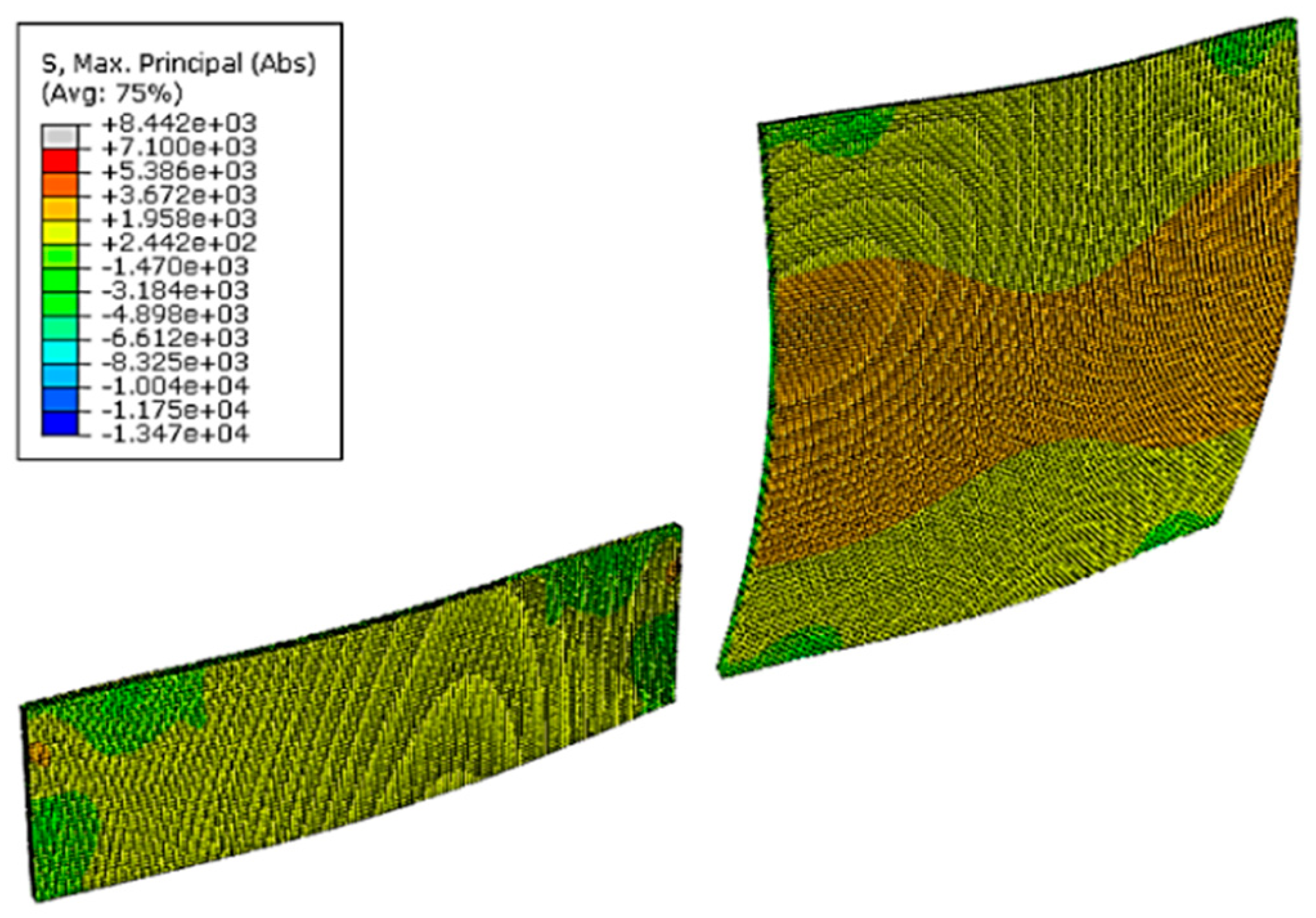
The simulations of the marble slabs applied in the building façades was performed with a 3D FEM model using the theory of thin plates and the two-step calibrated model. The slabs were supported by 4 nodes with translational restrains (in orthogonal directions x, y, z) and were submitted to evenly distributed loads that simulates the wind pressure acting on the perpendicular direction of the slabs surfaces, i.e., parallel to the marble stratification plane (Figure 12). The stability/resistance of the marble slabs to wind pressures (Wk) was evaluated through the flexural stress at the cross section of the slabs and through the loading/reaction forces at their fixings points (pin-dowel holes). The loading at the fixing points was obtained from the numerical model through the force-reaction static equilibrium, and the flexural/bending stress was assumed equal to the maximum principal tensile axial stresses.
The wind pressure/loading was determined through Eurocode 1 [17] standard calculation methodology, which takes into account the exposure conditions of the building façades (such as height, orientation, terrain roughness, surrounding constructions and obstacles, among other aspects) and the dynamic effects of wind speed on the building. The characteristic values for wind pressure (Wk) were obtained according to the position in height (h) of the stone slabs on the building façade:
  • For h ≤ 9 m − Wk = 1.3 kN/m2;
  • For 9 m < h ≤ 18 m − Wk = 2.1 kN/m2.
The stability/resistance of the stone slabs was evaluated for serviceability limit sates (SLS) associated with the risk of permanent/irreversible damage impairing functionality, and ultimate limit states (ULS) associated with the risk of collapsing due to loss of mechanical resistance, both defined in Eurocode 0 [33] through verification of the basic security condition/ratio:
Ssd/Rrd ≤ 1
Ssd is the design load or stress determined from the combinations defined in Eurocode 0 [33], i.e., the combination of the characteristic values of wind (Wk), calculated through Eurocode 1 [17], and the self-weight of the slabs (Gk), which is calculated through the average density of marble stone (2700 kg/m3) found in literature [6,9,10,11,12,13], acting simultaneously:
  • Combination SLS: Ssd = Gk + Wk;
  • Combination ULS: Ssd = 1.35 Gk + 1.5 Wk.
Rrd is the design load or flexural strength defined in Eurocode 0 [33]:
Rrd = η Rrk/γm
  • Rrk—Characteristic value obtained from statistical analysis of the lab tests results obtained in this study (minimum values obtained from a log-normal distribution with 75% confidence level and 5% fractile distribution—see Table 1);
  • γm—Partial safety factor determined through a semi-probabilistic approach adapted for stone cladding [18], using the experimental results obtained from lab tests performed in this study (for ULS γm equal to 2.4 and for SLS γm equal to 1);
  • η—Conversion factor to take into account several effects, namely temperature and humidity (since the stone in this case study was not in its initial conditions, i.e., it was submitted to 15 years of climate exposure, this factor was assumed equal to 1).
The verification of the basic security condition/ratio (4) was made in terms of either satisfying (S) or not satisfying (NS) the maximum loads/reactions at the dowel holes/support nodes (i.e., Fsd/Frd ≤ 1), and the maximum bending stresses at the cross section of the slab (i.e., σsd/σrd ≤ 1).

2.5. Lab Tests Results

The results obtained from lab tests are presented in Table 1, and the following aspects are highlighted:
  • The mineralogical/petrographic study revealed that the marble was made mainly of calcite, thus classified as a calcite marble, although containing other minerals in smaller quantities (dolomite, quartz, biotite and chlorite), and possessing a homogenous structure (granoblastic texture of fine equigranular grains);
  • The variation coefficient (C.V.) presents higher values for marble stone affected by bowing, being lower than 20% for most of the properties, except for the case of breaking load at the dowel hole (without bowing, 38%), which may be related to insufficient fixing of the test samples (provided by clamps);
  • Considering the experimental force-vertical displacements (FfL/2) obtained from flexural tests, the marble exhibits a linear behavior until 40 to 55% of the maximum/breaking load;
  • Relatively small differences between stone slabs with and without bowing were found for the flexural strength (5% for the mean value and 20% for the characteristic value) and for the compressive strength (11% for the mean value and 9% for the characteristic value);
  • Therefore, in average terms, there is no significant difference between the mechanical properties of stone slabs with and without bowing, which can be related with the scarce number of samples available for testing in this study;
  • The mechanical properties of marble in initial conditions of use (unaffected by aging/deterioration agents) were not available in this case study; however, comparing the experimental results obtained in this study with the range of average values found in literature for similar calcite marbles in initial conditions of use, a reduction between 23% to 70% was found for the flexural strength, 3% to 23% for the compressive strength and 3% to 34% for the static modulus of elasticity;

2.6. Numerical Simulations Results

The results obtained in the simulations are presented in Table 2, including the evaluation of stability/resistance according to basic security condition/ratio (4). The following aspects are highlighted:
  • The flexural/bending resistance of all marble slabs is verified for serviceability conditions (SLS security ratios are lower than 1, i.e., between 0.3 to 0.7), therefore presenting a low risk of damage/fracture due to bending caused by moderate wind pressures (as observed in the inspections made);
  • The load resistance at the dowel hole for serviceability conditions is not verified for slabs located higher than 9 m (SLS security ratios are, in general, higher than 1, i.e., between 1.2 to 1.7), thus presenting a high risk of occurring permanent damage/fracture near the slabs fixing points (as observed in the inspections made—see Figure 3);
  • The bending/flexural resistance and load resistance at the dowel hole are not verified for almost every case analyzed in ultimate limit states (ULS security ratios between 1 to 2.6 for bending and 1.2 to 6 for the load dowel hole), meaning that the stone slabs have a high risk of collapsing when exposed to extreme wind pressures, especially due to failure of the marble near the slab fixing points (ULS security ratios for the load dowel hole are higher than bending stress).

3. Discussion

The test results obtained in this case study were not entirely conclusive regarding the effect of bowing on the mechanical properties of the marble stone, since original stone slabs in initial use conditions (without bowing and aging effects) were not available and one could not have a large number of test samples. Moreover, the evaluation of the allowable deflections (e.g., established in EN 16306 [16]) or the evaluation of strength decay vs. bowing increase is difficult to perform/extrapolate without specific lab bowing test results, which were not available for this case study either.
Nevertheless, considering the minimum flexural strength obtained from tests and from similar calcite marbles found in literature, it was estimated, at least, a 23% reduction in the flexural strength caused by the combined effects of aging degradation and bowing. The estimated percentage of flexure strength decay and the bowing magnitude measured on site (5 mm/m) for this case study are near to the values found in some case studies of similar aged marble cladding [3]. However, other degradation aging effects may also have influenced the decay of strength in this case study, suggesting that this aspect should also be considered when analyzing ventilated marble cladding affected by bowing and wind pressures. Both bowing or/and aging degradation effects can be considered in the design through the conversion/reduction factor (η) found in Equation (4), which in practical terms will increase the safety factor (γm) used for the strength properties of the marble.
An estimative of the maximum wind resistance value can be given through the available empirical formulae [18] and using the flexure strength results obtained from the lab test. For this case study, assuming the characteristic values of flexural strength with and without bowing (σrk = 5.8 × 10³ N/m2) and maximum span between fixing points (1.3 to 1.5 m), the maximum characteristic value of wind pressure resistance (Wrk) ranges from 2.3 to 3.0 kN/m2. This pressure resistance value is higher than the characteristic values of acting wind pressure obtained through Eurocode 1 [17] (Wsk ranging from 1.3 to 2.1 kN/m2). However, considering the safety factors for the stone strength (γm = 2.4) and wind actions for ultimate limit states analysis (1.5) used in this case study, the wind pressure resistance obtained is lower (Wrk ranging from 0.7 to 0.8 kN/m2). This initial estimate indicates that, in spite of no significant permanent damage/stability risk in the marble slabs predicted for serviceability limit sates, a high risk of them collapsing is present in ultimate limit states analysis, i.e., for higher/extreme wind pressures the slabs affected by wind pressures and bowing/aging deterioration effects may fall from the façades. The numerical simulations performed confirmed this initial estimative.
As mentioned before, the fixing resistance of the slabs is referred to in literature as a critical factor, especially for slabs fixed with dowel-hole anchorage systems [18,23]. However, a reliable range of values for the comparison of the breaking load at the dowel hole is difficult to establish. This strength property is dependent on many details related to fixing/installation conditions of the slabs [18,23], which can be difficult to obtain from literature (hole/pin diameter, depth and position in the stone thickness, stone thickness and strength, rigidity of the pin/hole connection and hole-drilling conditions). Nevertheless, the experimental values of breaking the load at dowel hole obtained in lab tests can give a more accurate and easier estimation of the maximum wind pressure resistance given by slab fixing points. For this case study, considering the characteristic values of breaking load at dowel hole (slabs with and without bowing Fr = 0.596 × 10³ N), number of fixing points (4) and the maximum wind exposure surfaces of the slabs (1.65 to 1.88 m2), the maximum characteristic value of wind pressure resistance (Wrk) can be estimated between 1.3 to 1.4 kN/m2. This wind resistance value is very close or lower than the characteristic values of acting wind pressures obtained through Eurocode 1 [17] (Wsk ranging from 1.3 to 2.1 kN/m2), thus presenting a high risk of slabs collapsing from the façade when affected by wind pressure and bowing/aging deterioration effects, either for serviceability limit sates and ultimate limit states analysis. The numerical simulations performed also confirmed this initial estimative.
The 3D FEM numerical simulations performed with the two-step simplified material model calibrated through lab tests, allowed a more complete and detail analysis of several marble slabs affected by wind pressure and bowing/aging deterioration effects in the analyzed case study. The results obtained revealed, as previously estimated, stability problems on the marble slabs in use, especially for extreme wind conditions/pressures (ultimate limit states), thus presenting a high risk of collapsing from the building during its remaining service life. The main reason for the security risk is the high stress levels induced by the wind pressure acting on slabs with large surface/side dimensions (i.e., higher than the reference limits found in literature [20]), combined with bowing and possibly other aging effects that decreased the stone mechanical strength (at least 23% for the flexural/bending strength). The risk of permanent damage or failure/collapse is higher at the slabs’ fixing points since the ratios given by the basic security condition (4) for the loading at the dowel hole are significantly higher than security ratios for the bending stresses, either for serviceability limit sates and ultimate limit states analysis. Therefore, the pin dowel fixing system used is the most critical factor for the stability of the marble slabs analyzed in this study, thus following the tendency mentioned in other works [18,23].

4. Conclusions

The bowing can cause significant aesthetic degradation, irreversible damage and significant strength decay in the marble slabs, and the most usual repairing interventions are expensive and involve removing the affected slabs and replacing them with other cladding solutions (e.g., other marble less prone to bowing or other type of stone). The bowing phenomena combined with wind pressures can severely impair the security level of ventilated marble cladding, as was demonstrated by the case study. The results obtained in this study revealed that a higher risk of failure/collapse of marble slabs might occur when these are simultaneously affected by wind pressures and by bowing, or eventually other aging deterioration effects, during its use on ventilated façades. This has highlighted the fixing resistance given by pin-dowel anchorage systems, since this propriety was found to be more affected than the flexural strength of the marble slabs, therefore being the most influencing factor for the high risk of failure/collapse of the marble slabs analyzed in this study.
It was demonstrated in this study that analyses based on lab tests and calibrated numerical simulations can be helpful to evaluate the stability/security conditions of marble slabs affected by bowing or/and other degradation agents, either for slabs already in use or to be used in ventilated cladding. However, bowing lab tests should be performed (e.g., adopting the EN 16,306 [16] test method) in order to allow a more accurate prediction/evaluation of the bowing trend and possible magnitude, including strength decay of the marble (flexural strength and loading resistance at the slab fixings). This strength decay should be considered in the design through the increase of the available safety factors for stone cladding or using conversion/reduction factors for the stone strength properties. Moreover, stress-strain data obtained from direct tensile/compressive tests performed on stone samples could also be useful when used in more advanced simulations made with non-linear elastic-plastic models available for brittle/quasi brittle materials. It is highlighted the importance of obtaining test samples of stone slabs on its initial use/undamaged conditions, which may be difficult in existing building façades.
Therefore, additional investigation is still needed in order to improve the extrapolation of laboratory results to the façades of buildings and to improve the available design procedures, therefore avoiding high security risks and costly interventions caused by bowing, thus ensuring a proper durability to the marble ventilated cladding. Nevertheless, despite the need of additional investigation, the existing developments concerning bowing should be used in the design of ventilated marble cladding.

Author Contributions

H.S. and R.S. both contributed to the conceptualization, methodology validation, data curation, writing (original draft preparation and review), editing and supervision of the paper.

Funding

This research received no external funding.

Conflicts of Interest

The authors declare no conflict of interest.

References

  1. Loughran, P. Failed Stone: Problems and Solutions with Concrete and Masonry; Birkhäuser—Publishers for Architecture: Basel, Switzerland, 2007; pp. 1–159. [Google Scholar]
  2. Neto, N.; de Brito, J. Validation of an inspection and diagnosis system for anomalies in natural stone cladding (NSC). Constr. Build Mater. 2012, 30, 224–236. [Google Scholar] [CrossRef]
  3. Akesson, U.; Lindqvist, J.E.; Schouenborg, B.; Grelk, B. Relationship between microstructure and bowing properties of calcite marble claddings. Bull. Eng. Geol. Environ. 2006, 65, 73–79. [Google Scholar] [CrossRef]
  4. Siegesmund, S.; Ruedrich, J.; Koch, A. Marble bowing: Comparative studies of three different public building façade. Environ. Geol. 2008, 56, 473–494. [Google Scholar] [CrossRef]
  5. Koch, A.; Siegesmund, S. The combined effect of moisture and temperature on the anomalous expansion behaviour of marble. Environ. Geol. 2004, 46, 350–363. [Google Scholar] [CrossRef]
  6. Erlin, B. Contribution to a better understanding of the mechanism causing dishing failures of the Carrara marble used for outside on building facades. In Dimension Stone Cladding: Design, Construction, Evaluation, and Repair; Hoigard, K.R., Ed.; ASTM International: West Conshohocken, PA, USA, 2000; pp. 71–78. [Google Scholar]
  7. Beouch, R.; Fichet, O.; Bigas, J.P.; Teyssie, D.; Berthier, B.; Prichystal, J.B. Cracks and stains on facade-cladding made of carbonate rock thin panels. Struct. Surv. 2012, 30, 130–144. [Google Scholar]
  8. Logan, J.M. On-site and laboratory studies of strength loss in marble on building exteriors. In Fracture and Failure of Natural Building Stones; Kourkoulis, S.K., Ed.; Springer: Houten, The Netherlands, 2006; pp. 345–362. [Google Scholar]
  9. de Gennaro, R.; Calcaterra, D.; di Girolamo, P.; Langella, A.; de Gennaro, M. Discovering the stone heritage of southern Italy: Technical properties of the Mondragone marble from Campania region. Environ. Geol. 2003, 44, 266–276. [Google Scholar] [CrossRef]
  10. Papamichos, E.; Papanicolopulos, S.A.; Larsen, I. Mechanical properties and damage diagnosis of natural building stones. In Fracture and Failure of Natural Building Stones; Kourkoulis, S.K., Ed.; Springer: Houten, The Netherlands, 2006; pp. 71–92. [Google Scholar]
  11. Siegesmund, S.; Dürrast, H. Physical and Mechanical Properties of Rocks. In Stone in Architecture, 4th ed.; Siegesmund, S., Snethlage, R., Eds.; Springer: Berlin/Heidelberg, Germany, 2011; pp. 97–225. [Google Scholar]
  12. Amaral, P.M.; Fernandes, J.C.; Pires, V.; Rosa, L.G. Ornamental Stones. In Materials for Construction and Civil Engineering; Gonçalves, M.C., Margarido, F., Eds.; Springer: Cham, Switzerland, 2015; pp. 397–445. [Google Scholar]
  13. Rochas Ornamentais Portuguesas. Available online: http://rop.lneg.pt/rop/ (accessed on 23 January 2018).
  14. Grelk, B.; Christiansen, C.; Schouenborg, B.; Malaga, K. Durability of Marble Cladding—A Comprehensive Literature Review. J. ASTM Int. 2007, 4, 1–19. [Google Scholar] [CrossRef]
  15. Bellopede, R.; Castelletto, E.; Schouenborg, B.; Marini, P. Assessment of the European Standard for the determination of resistance of marble to thermal and moisture cycles: Recommendations for improvements. Environ. Earth Sci. 2016, 75, 1–9. [Google Scholar] [CrossRef]
  16. CEN. EN 16306—Natural Stone Test Methods: Determination of Resistance of Marble to Thermal and Moisture Cycles; European Committee for Standardization: Brussels, Belgium, 2013. [Google Scholar]
  17. CEN. EN 1991-1-4—Eurocode 1: Actions on Structures, Part 1–4: General Actions—Wind Actions; European Committee for Standardization: Brussels, Belgium, 2010. [Google Scholar]
  18. Camposinhos, R.S. Stone Cladding Engineering; Springer: Dordrecht, The Netherlands, 2014; pp. 1–171. [Google Scholar]
  19. ASTM. Dimension Stone Cladding: Design, Construction, Evaluation, and Repair; ASTM International: West Conshohocken, PA, USA, 2000; pp. 1–194. [Google Scholar]
  20. AFNOR. DTU 55.2 (NF P 65-202-1): Travaux de Bâtiment—Revêtements Muraux Attachés en Pierre Mince—Partie 1: Cahier des Clauses Techniques; Association Française de Normalisation: La Plaine Saint-Denis, France, 2000. [Google Scholar]
  21. Lewis, M.D. Modern Stone Cladding: Design and Installation of Exterior Dimension Stone Systems; ASTM International: West Conshohocken, PA, USA, 1995; pp. 1–146. [Google Scholar]
  22. Marble Institute of America. Dimension Stone Design Manual, 8th ed.; Marble Institute of America: East Lorain St. Oberlin, OH, USA, 2016. [Google Scholar]
  23. Camposinhos, R.S.; Camposinhos, R.A. Dimension-stone cladding design with dowel anchorage. Proc. Inst. Civ. Eng. Constr. Mater. 2009, 162, 95–104. [Google Scholar] [CrossRef]
  24. Moreiras, S.; Paraguassu, A.; Ribeiro, R. Dimension stone for building facades: Methodology for structural design. Bull. Eng. Geol. Environ. 2008, 67, 53–57. [Google Scholar] [CrossRef]
  25. Camposinhos, R. Dimension stone design—Partial safety factors: A reliability based approach. Proc. Inst. Civ. Eng. Constr. Mater. 2012, 165, 145–159. [Google Scholar] [CrossRef]
  26. Piresa, V.; Pacheco, A.; Infante, V.; Amaral, P.M.; Rosa, L.G. Finite element model development applied to portuguese granites for contact analysis of two dowel fixing conditions used in cladding. Key Eng. Mater. 2013, 548, 255–266. [Google Scholar] [CrossRef]
  27. Camposinhos, R.S.; Camposinhos, R.A. Dimension stone design – kerf anchorage in limestone and marble. Proc. Inst. Civ. Eng. Constr. Mater. 2012, 165, 161–175. [Google Scholar]
  28. Mahabadi, O.K.; Cottrell, B.E.; Grasselli, G. An example of realistic modelling of rock dynamics problems: FEM/DEM simulation of dynamic Brazilian test on barre granite. Rock Mech. Rock Eng. 2010, 43, 707–716. [Google Scholar] [CrossRef]
  29. Lubliner, J.; Oliver, J.; Oller, S.; Onate, E. A plastic damage model for concrete. Int. J. Solid Struct. 1989, 25, 299–326. [Google Scholar] [CrossRef]
  30. Jankowiak, T.; Lodygowski, T. Identification of parameters of concrete damage plasticity constitutive model. Found. Civ. Environ. Eng. 2005, 6, 53–69. [Google Scholar]
  31. Sousa, R.; Sousa, H.; Guedes, J. Diagonal compressive strength of masonry samples-experimental and numerical approach. Mater. Struct. 2013, 46, 765–786. [Google Scholar] [CrossRef]
  32. Sousa, R.; Guedes, J.; Sousa, H. Characterization of the uniaxial compression behaviour of unreinforced masonry—Sensitivity analysis based on a numerical and experimental approach. Arch. Civ. Mech. Eng. 2015, 15, 532–547. [Google Scholar] [CrossRef]
  33. CEN. EN 1990—Eurocode 0: Basis of Structural Design; European Committee for Standardization: Brussels, Belgium, 2010. [Google Scholar]
  34. CEN. EN 1469—Natural Stone Products, Slabs for Cladding, Requirements; European Committee for Standardization: Brussels, Belgium, 2015. [Google Scholar]
  35. EOTA. Kits for External Wall Claddings Mechanically Fixed (EAD 090062-00-0404); European Organization for Technical Assessment: Brussels, Belgium, 2018. [Google Scholar]
  36. CEN. EN 13161—Natural Stone Test Methods: Determination of Flexural Strength under Constant Moment; European Committee for Standardization: Brussels, Belgium, 2008. [Google Scholar]
  37. CEN. EN 1926—Natural Stone Test Methods: Determination of Uniaxial Compressive Strength; European Committee for Standardization: Brussels, Belgium, 2006. [Google Scholar]
  38. CEN. EN 14146—Natural Stone Test Methods: Determination of the Dynamic Modulus of Elasticity (by Measuring the Fundamental Resonance Frequency); European Committee for Standardization: Brussels, Belgium, 2004. [Google Scholar]
  39. CEN. EN 13364—Natural Stones Test Methods: Determination of Breaking Load at Dowel Hole; European Committee for Standardization: Brussels, Belgium, 2001. [Google Scholar]
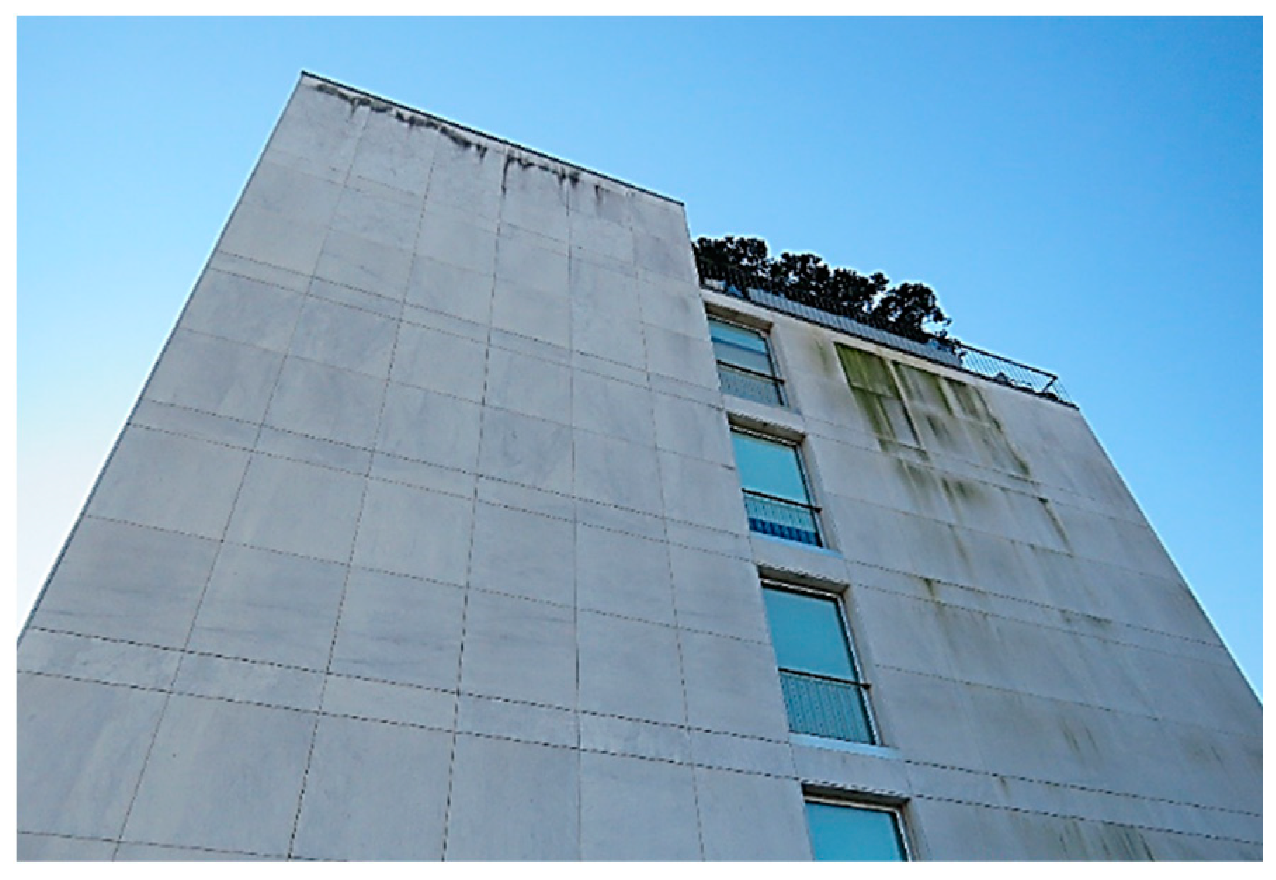
Figure 1. Partial view of the stone cladding applied on the north façade of the building.
Buildings 09 00229 g001
Figure 2. Detail view of cladding after removal of a stone slab (dowel anchorage system/fixing points).
Buildings 09 00229 g002
Figure 3. Examples of bowing and damage detected on the marble cladding: (a) bowing of slabs in the east and west façades; (b) local damage/fracture near the fixing points of the slabs.
Buildings 09 00229 g003
Figure 4. Examples of stone slabs removed from the building façade: (a) east side; (b) south side.
Buildings 09 00229 g004
Figure 5. Position of the test specimens cut out from the slabs removed from the façade (dimensions in cm): (a) flexural strength; (b) compressive strength; (c) breaking load at dowel hole south side.
Buildings 09 00229 g005
Figure 6. Examples of flexural strength and static modulus of elasticity lab tests (top side of the specimen is the sun/wind-exposed surface): (a) static model of the test; (b) test set-up with loading direction (F); (c) specimen after breaking load; (d) force-displacement curves and regression analysis.
Buildings 09 00229 g006
Figure 7. Examples of compressive strength lab tests: (a) test set-up with loading direction; (b) specimen after breaking load.
Buildings 09 00229 g007
Figure 8. Examples of breaking load at the dowel whole (top side of the specimen is the sun/wind-exposed surface): (a) test set-up with loading direction (F); (b) specimen after breaking.
Buildings 09 00229 g008
Figure 9. Examples of dynamic modulus of elasticity measurement: (a) transversal direction; (b) longitudinal direction.
Buildings 09 00229 g009
Figure 10. Examples of petrographic/mineralogical analysis of marble: (a) images from petrographic microscope (enlarged 10 ×); (b) images from electronic microscope (enlarged 60 ×).
Buildings 09 00229 g010
Figure 11. Validation/calibration of the numerical model (simulation vs. test data).
Buildings 09 00229 g011
Figure 12. Examples of finite element model (FEM) simulations of marble stone slabs and stress distribution associated to wind pressure for serviceability limit sates (SLS) characteristic combination (values in ×103 Pa).
Buildings 09 00229 g012
Table 1. Test results obtained from marble stone specimens.
PropertyBowing EffectN° SpecimensUnitsMean ValueCharacteristic ValueC.V. (%)
Flexural strength (σr)Without8Pa × 1068.26.59.8
With147.85.317.8
With + Without227.95.815.1
Compressive strength (Rr)Without5Pa × 10681.563.85.0
With572.557.98.6
With + Without1077.062.29.2
Breaking load at dowel hole (Fr)Without5N × 1031.190.67118.7
With41.150.43338.4
With + Without91.170.59629.2
Dynamic modulus of elasticity (EdL/EdT for ν = 0.25)With4Pa × 10938.8/40.933.8/28.04.8/11.8
Dynamic modulus of elasticity (EdL/EdT for ν = 0.40)With4Pa × 10921.7/22.918.9/15.7
Static modulus of elasticity (EsL)With4Pa × 10916.58.518.0%
Table 2. Results obtained in FEM simulations and evaluation of stability.
Stone Slabs and Surface Dimensions (m)Security CriteriaBending Stress (106 × Pa)Load at Dowel Hole (103 × N)
SLSULSSLSULS
h ≤ 9 m9 < h ≤ 18 mh ≤ 9 m9 < h ≤ 18 mh ≤ 9 m9 < h ≤ 18 mh ≤ 9 m9 < h ≤ 18 m
Buildings 09 00229 i001Max.Value1.72.72.54.00.540.870.801.3
Sd/Rd0.30.51.01.70.91.53.25.2
ResultSSNSNSSNSNSNS
Buildings 09 00229 i002Max.Value2.03.23.04.80.200.320.300.49
Sd/Rd0.30.61.22.00.30.51.22.0
ResultSSNSNSSSNSS
Buildings 09 00229 i003Max.Value3.14.34.466.250.530.730.761.0
Sd/Rd0.50.71.82.60.91.23.14.1
ResultSSNSNSSNSNSNS
Buildings 09 00229 i004Max.Value1.62.62.44.00.600.990.921.5
Sd/Rd0.30.51.01.61.01.73.76.0
ResultSSNSNSSNSNSNS