Next Article in Journal
Learning-Based Cooperative Adaptive Cruise Control
Next Article in Special Issue
3D-Printed Miniature Robots with Piezoelectric Actuation for Locomotion and Steering Maneuverability Applications
Previous Article in Journal
Adaptive Control of Chaotic Signals: Investigated by Simulation Software and Real Electronic Circuits
Previous Article in Special Issue
Optimal Design of Magneto-Force-Thermal Parameters for Electromagnetic Actuators with Halbach Array
 
 
Retraction published on 16 February 2023, see Actuators 2023, 12(2), 88.
Article

RETRACTED: A Closed-Loop Control Mathematical Model for Photovoltaic-Electrostatic Hybrid Actuator with a Slant Lower Electrode Based on PLZT Ceramic

1
School of Mechanical Engineering, Nanjing University of Science and Technology, Nanjing 210094, China
2
School of Mechanical and Electrical Engineering, Henan University of Technology, Zhengzhou 450001, China
*
Author to whom correspondence should be addressed.
Actuators 2021, 10(11), 285; https://doi.org/10.3390/act10110285
Submission received: 27 August 2021 / Revised: 20 October 2021 / Accepted: 21 October 2021 / Published: 25 October 2021 / Retracted: 16 February 2023
(This article belongs to the Special Issue Miniature and Micro-Actuators)

Abstract

:
In this paper, a novel photovoltaic-electrostatic hybrid actuator with a slant lower electrode based on the PLZT ceramic is proposed. The mathematical model of photovoltaic-electrostatic hybrid actuator is established. Then, based on the mathematical model of photovoltaic-electrostatic hybrid actuator and the parameters identified, the mathematical simulation of the closed-loop displacement control for the photovoltaic-electrostatic hybrid actuator based on the PLZT ceramic is carried out. The results show that the displacement of the actuator can be controlled successfully at a particular value within the pull-in displacement by the light source. Furthermore, the response speed of the output displacement for photovoltaic-electrostatic hybrid actuator with a slant lower electrode is faster than that with a parallel lower electrode, offering a good potential to advance the current applications on micro-electro-mechanical system.

1. Introduction

The micro-actuator plays a crucial role in a micro-electro-mechanical-system (MEMS) and micro-electro-opto-mechanical-system (MOEMS), and the electrostatic actuator is widely used in MEMS and MOEMS because of its advantages of fast response and good reliability [1,2]. However, the traditional electrostatic actuator inevitably generates electromagnetic noise, which disrupts the system and causes the system to fail to work properly. Micro-driving based on smart materials has promoted considerable progress in the development of new micro-actuators. Photovoltaic materials, such as lead-lanthanum zirconate-titanate (PLZT) ceramic, are able to transform light energy into mechanical energy. When PLZT ceramic is irradiated by ultraviolet (UV) light with a wavelength near 365 nm, a high-value photovoltage is generated in the polarization direction due to the anomalous photovoltaic effect [3], which can be applied on the electrostatic actuator through the wire to drive the electrostatic actuator. Therefore, the PLZT ceramic can be employed to be the energy device for the photovoltaic-electrostatic hybrid actuator. Besides solving the problem of electromagnetic interference completely, a photovoltaic-electrostatic hybrid actuator possesses some other advantages, such as non-contact remote control, green energy driving, and so on.
In recent years, many scholars have carried out a lot of research on the application of PLZT ceramics in active vibration control and micro driving. For the active vibration control based on PLZT ceramic, Yue et al. [4] presented a new multiple degree-of-freedom photostrictive actuator configuration for shell vibration control. Jiang et al. [5] studied the active vibration control of an open cylindrical shell based on a 0–3 polarized PLZT photostrictive actuator. Zheng et al. [6] proposed a novel genetic algorithm-based controlling algorithm for multi-modal vibration control of beam structures via a photostrictive actuator. He et al. [7] proposed a novel multipiece actuator configuration and a self-organizing fuzzy sliding mode control method to suppress multimodal vibration of cylindrical shells. In addition, for the micro driving with PLZT ceramic, Kikuchi et al. [8] studied the photostrictive characteristics of PLZT. Lu et al. [9] proposed a driven servo system model based on PLZT ceramic. However, in our previous research, experiments had been carried out to confirm that the temperature elevation of a PLZT ceramic exposed to UV light results in a slow response of the photo-induced deformation and the hysteresis phenomenon between the photovoltage and the photo-induced deformation [10]. Huang et al. [11] proposed a mathematical model of PLZT ceramic with coupled multi-physics fields, and it can explain the hysteresis phenomenon and the variation trend of the photo-induced voltage very well. To remedy the hysteresis phenomenon of PLZT ceramic actuator, Jiang and Wang et al. [12,13] studied a novel hybrid photovoltaic-piezoelectric actuation mechanism and Liu et al. [14] investigated on influence factors of opto-electrostatic hybrid driving torsion actuator based on PLZT ceramic. Wang et al. [15] studied the closed-loop control of the photovoltage of PLZT ceramic. The photovoltaic-piezoelectric and opto-electrostatic hybrid actuation can eliminate the hysteresis phenomenon between the photovoltage and the photo-induced deformation. However, the driving response of opto-electrostatic hybrid actuation based on PLZT ceramic should be further improved through optimization for the electrostatic driving structure.
In this paper, a novel photovoltaic-electrostatic hybrid actuator with a slant lower electrode based on the PLZT ceramic is proposed to improve the driving response of the photovoltaic-electrostatic hybrid actuator. Then, the mathematical model of the photovoltaic-electrostatic hybrid actuator is established. The experiments are carried out to get the photovoltage parameters during the illumination and non-illumination phase. After that, we present equations for the closed-loop displacement control of the hybrid actuator. Based on the photovoltage parameters and the closed-loop control equations, the driving performance for the photovoltaic-electrostatic hybrid actuator is analyzed through the mathematical simulation.

2. Mathematical Modeling of Photovoltaic-Electrostatic Hybrid Actuator with a Slant Lower Electrode

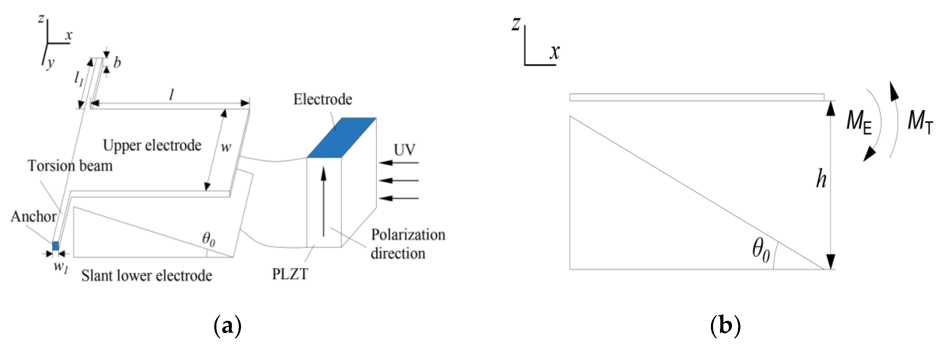
2.1. Photovoltaic-Electrostatic Hybrid Actuator

The photovoltaic-electrostatic hybrid actuator, which consists of the PLZT ceramic and electrostatic actuator with a slant lower electrode, is illustrated in Figure 1. They are connected through wires using the conductive silver paste. As the PLZT ceramic is illuminated by the UV light near 365 nm, the photovoltage in the polarization direction of PLZT ceramic generates and increases rapidly, and, when the UV light is turned off, the photovoltage decreases rapidly. In this way, the photovoltage between the two electrodes of PLZT ceramic can be controlled in a timely manner by the controllable light source and applied to the electrostatic actuator through wires to drive the electrostatic actuator. The structure parameters of the photovoltaic-electrostatic hybrid actuator are listed in Table 1.

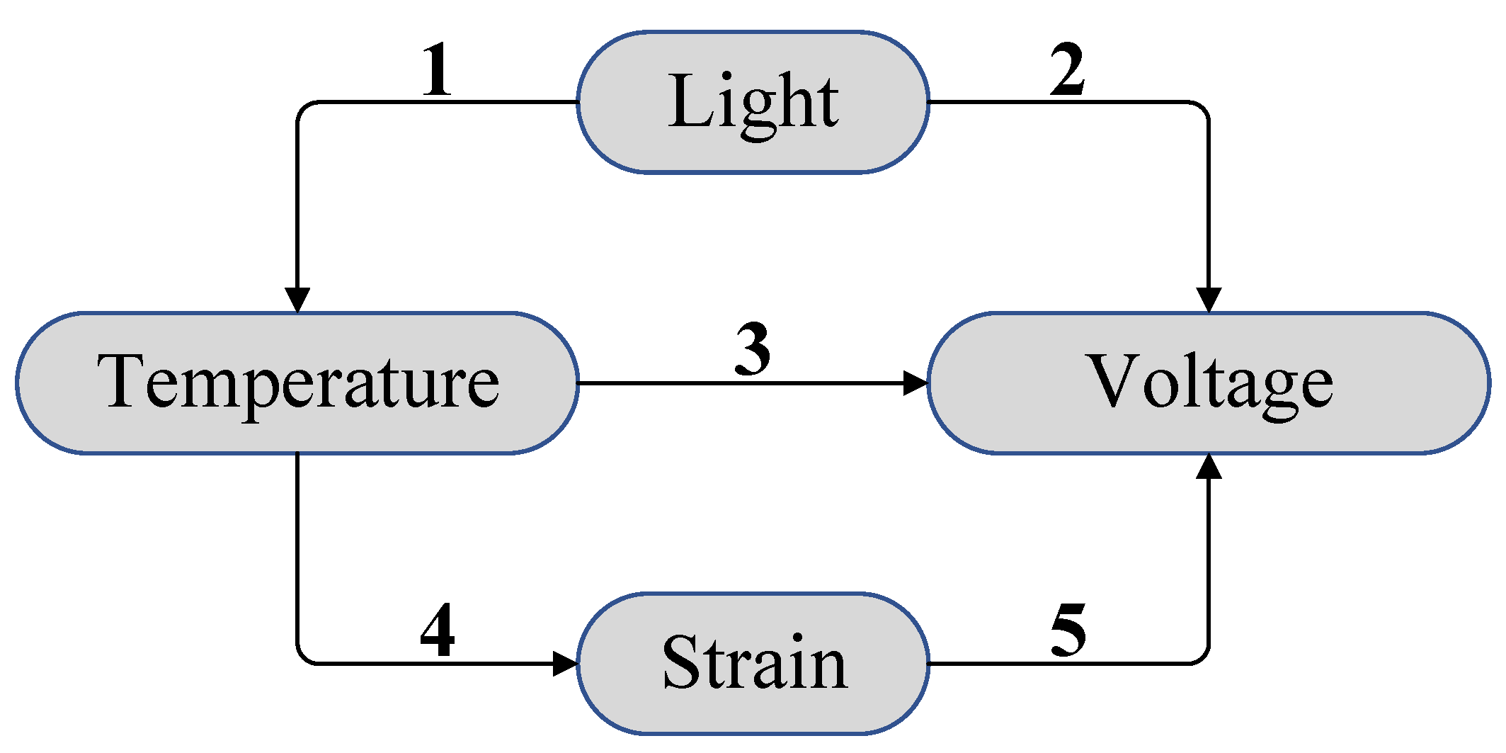
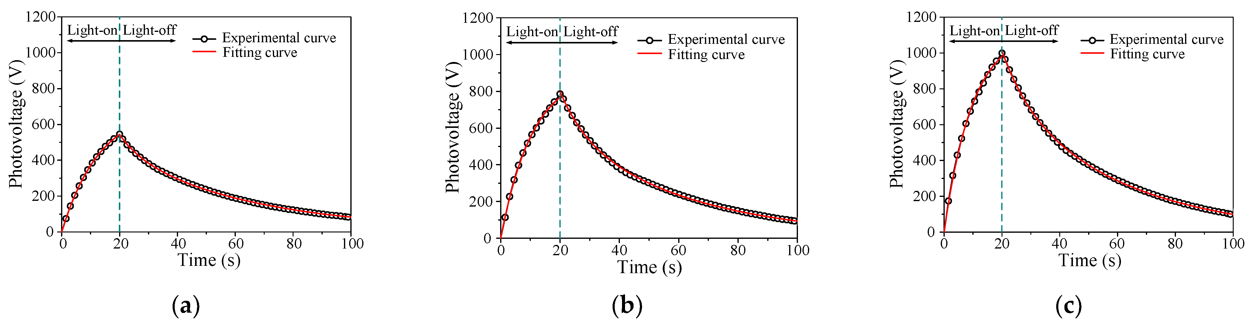
2.2. Mathematical Modeling of Photovoltage of PLZT Ceramic

The photovoltage effect of PLZT ceramic originates from the interaction of the anomalous photovoltaic effect, pyroelectric effect, and direct piezoelectric effect, according to our previous research [11]. Figure 2 shows the coupling relationships of opto-electric-thermo-mechanic fields of PLZT ceramic illuminated by UV light. It should be noted that the electric fields generated through the anomalous photovoltaic effect and pyroelectric effect are in the same direction with the polarization direction. In contrast, the electric field produced by the direct piezoelectric effect is in the opposite direction. According to the mechanism analysis of the coupled multi-physics field, during the illumination phase, the photovoltage of the PLZT ceramic can be simplified as [11]:
V ( t ) = V S ( 1 e t / τ ) ,
where VS is the saturated photovoltage, τ is the time constant during the illumination phase, and t is the illumination time.
When the UV light is turned off at t0, the photovoltage in the polarization direction of PLZT ceramic can be expressed as [16]:
V d ( t ) = V ( t 0 ) ( A P C p β 2 λ D e d 3 i Y a ) Δ T s d + A P C p Δ T s d e t / τ d 1 β 2 λ D e d 3 i Y a Δ T s d e t / τ d 2
where A is the electrode area of PLZT ceramic; P is the pyroelectric coefficient of PLZT ceramic; Cp is capacitance [17]; λ is the thermal stress coefficient of PLZT ceramic; β2 is the conversion coefficient of the thermal deformation and electric field during the non-illumination phase; De is the distance between the two electrodes of PLZT ceramic; d3i is the piezoelectric constant of the PLZT ceramic, where i is the direction of the photostrictive strain in the coordinates system of the PLZT ceramic, I = 1,2,3; Ya is the elastic modulus of PLZT ceramic; △Ts−d is the maximal temperature decrement during the non-illumination phase; and τd1 and τd2 are the time constants of the pyroelectric effect and thermal elasticity effect during the non-illumination phase, respectively. Equation (2) can be simplified as:
V d ( t ) = V 0 + A 1 e t / τ d 1 + A 2 e t / τ d 2 ,
where V0 = V(t0)−(AP/CPβ2λDe/d3iYa)△Ts−d; A1 = (AP/CP)△Ts−d and A2 = −(β2λDe/d3iYa)△Ts−d.

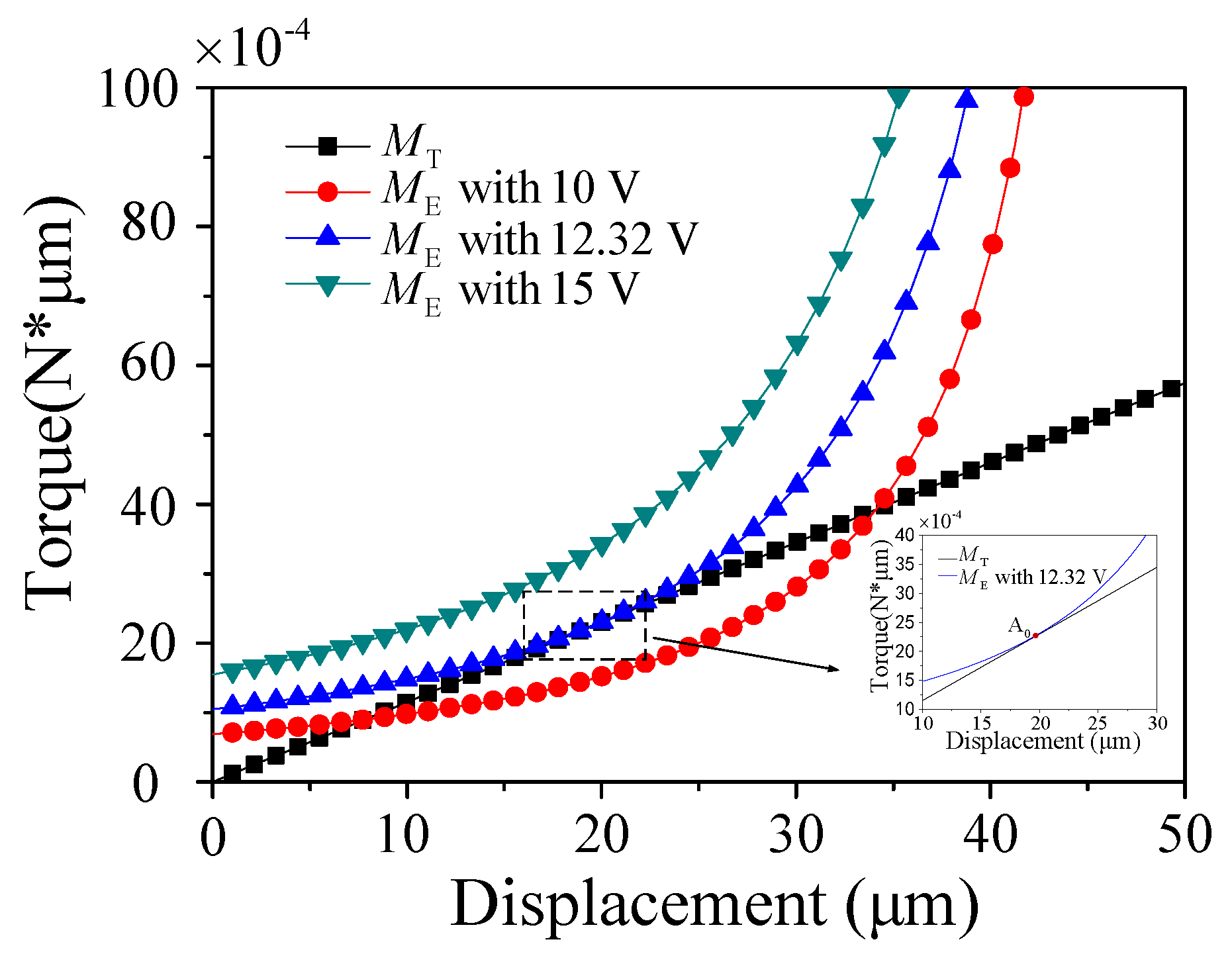
2.3. Mechanical Modeling of Photovoltaic-Electrostatic Hybrid Actuator

As shown in Figure 1, when the photovoltage is applied between the upper and lower electrodes through the wires, an electrostatic torque will be generated to cause the upper electrode to move downward. The electrostatic torque can be expressed as:
M E = ε 0 w V 2 2 0 l x [ h x θ tan θ 0 ( l x ) ] 2 d x = ε 0 w V 2 2 ( tan θ 0 θ ) 2 [ ln l θ h l tan θ 0 h l ( θ tan θ 0 ) l θ h ]
where ε0 is the permittivity of vacuum, of which the value is taken to be 8.85 × 10⁻¹² F/m. θ is the rotation angle of the cantilever beam, and θ0 is the slant angle of the lower electrode.
As shown in Equation (4), it is obvious that ME rapidly increases with the increase of θ0. That is to say, when the target displacement of the actuator is the same, the required driving voltage of photovoltaic-electrostatic hybrid actuator with a slant lower electrode is smaller than that with a parallel lower electrode, resulting in that the response speed of the output displacement for the photovoltaic-electrostatic hybrid actuator with a slant lower electrode is faster than that with a parallel lower electrode.
According to the theory of mechanics, when the electrostatic torque is applied to the electrostatic driving structure, a restoring torque will be generated on the torsion beam to balance the electrostatic torque. The restoring torque of the torsion beam can be expressed as a function of the rotation angle, given by
M T = K θ = 2 G b w 1 3 θ 3 l 1 [ 1 192 w 1 b π 5 tanh ( b π 2 w 1 ) ] ,
where G is the shear modulus of electrode material (Si), of which the value is taken to be 5.2 × 10¹⁰ Pa, and K is the torsion constant of torsion beam.
Ignoring the effect of gravity and air damping, electrostatic torque and restoring torque are balanced when the cantilever beam reaches a stable state. Thus, the relation between the driving voltage and offset angle of cantilever beam can be given by
V 2 = 4 G b w 1 3 θ ( tan θ 0 θ ) 2 3 ε 0 w l 1 × 1 192 w 1 b π 5 tanh ( b π 2 w 1 ) ln l θ h l tan θ 0 h l ( θ tan θ 0 ) l θ h ,
where the relation between θ and the displacement of the upper electrode tip S can be expressed as:
tan θ = S l .
Substituting Equation (1) into Equation (6), we can obtain the relation between the offset angle of cantilever beam and time, given by
[ V S ( 1 e t / τ ) ] 2 = 4 G b w 1 3 θ ( tan θ 0 θ ) 2 3 ε 0 w l 1 × 1 192 w 1 b π 5 tanh ( b π 2 w 1 ) ln l θ h l tan θ 0 h l ( θ tan θ 0 ) l θ h .

3. Closed-Loop Control Method of Photovoltaic-Electrostatic Hybrid Actuator with a Slant Lower Electrode

3.1. Parameters Identification

The photovoltage parameters in Equations (1) and (3) can be identified through experiments. Figure 3 shows the curves of photovoltage of the PLZT ceramic with the light of 20 mW/cm2, 40 mW/cm2, and 60 mW/cm2, respectively. The PLZT specimens tested in this paper are the PLZT (3/52/48) ceramics provided by the Shanghai Institute of Ceramics, Chinese Academy of Science, Shanghai, China. In the experiments, the UV light is turned off after the illumination of 20 s. As shown in Figure 3, a rapid increase of photovoltage is followed by increasing of illumination time (0–20 s). With the rise of light intensity, the voltage goes up faster and faster. When the light is turned off, the photovoltages decrease, and the greater the light intensity is, the faster the speed can be obtained.
Based on the experimental data of the photovoltage under irradiation of 20 mW/cm2, 40 mW/cm2, and 60 mW/cm2, the fitting value of VS, τ, V0, A1, A2, τd1, τd2 can be identified through Equations (1) and (3). When the light intensity is 20 mW/cm2, the photovoltage of PLZT ceramic can be finally written as:
{ V ( t ) = 694.3520 ( 1 e t 13.0634 )          ( t < 20 ) V d ( t ) = 1522.1006 e t 7.1986 + 684.5588 e t 44.8564 + 9.0043     ( t 20 )      .
When the light intensity is 40 mW/cm2, the photovoltage of PLZT ceramic can be finally written as:
{ V ( t ) = 908 . 3209 ( 1 e t 10 . 7538 )          ( t < 20 ) V d ( t ) = 2140 . 1163 e t 8 . 6733 + 919 . 9657 e t 43 . 7224 + 0 . 0266     ( t 20 ) .
When the light intensity is 60 mW/cm2, the photovoltage of PLZT ceramic can be finally written as:
{ V ( t ) = 1127 . 7553 ( 1 e t 9 . 8232 )            ( t < 20 ) V d ( t ) = 1239 . 8818 e t 42 . 4285 + 2096 . 6772 e t 9 . 4857 18 . 3623     ( t 20 ) .
Table 2 shows the fitting values of the identified parameters. Figure 4 shows the experimental and fitting curves of photovoltage of PLZT ceramic illuminated by the light intensities of 20 mW/cm2, 40 mW/cm2, and 60 mW/cm2.

3.2. Closed-Loop Control Equations

According to the mathematical model of the photovoltaic-electrostatic actuator established, the flow chart of the closed-loop displacement control of photovoltaic-electrostatic hybrid actuator based on PLZT ceramic is illustrated in Figure 5.
On the basis of mathematical models and the flow sheet for the closed-loop displacement control of photovoltaic-electrostatic hybrid actuator, the closed-loop control equations of the displacement of the photovoltaic-electrostatic hybrid actuator based on the PLZT ceramic can be obtained as follows.
{ V ( t ( m + 1 ) j ) = V ( t m j ) + ( V S τ e t m j / τ ) Δ t         ( S ( t m j ) S )         S ( t ( m + 1 ) j ) = f ( V ( t ( m + 1 ) j ) )           t n j ( n = 0 ) = V d 1 ( V ( t m j ) )           ( S ( t ( m 1 ) j ) S , S ( t m j ) > S )       V d ( t ( n + 1 ) j ) = V d ( t n j ) ( V S τ e t n j / τ + A 1 τ d 1 e t n j / τ d 1 + A 2 τ d 2 e t n j / τ d 2 ) Δ t     ( S ( t n j ) > S t )    S ( t ( n + 1 ) j ) = f ( V d ( t ( n + 1 ) j ) )            t m ( j + 1 ) ( m = 0 ) = V 1 ( V d ( t n j ) )         ( S ( t ( n 1 ) j ) > S t , S ( t n j ) S t )       t = j ( m j + n j ) Δ t ,
where S is the target displacement value; Δt is the sampling time; j is the number of on–off control cycles; mj and nj are the numbers of sampling periods during the illumination phase and non-illumination phase, respectively; f is the inverse function of the displacement and photovoltage applied on electrostatic actuator; Vd−1(V(t)) is the inverse function of the time and photovoltage of PLZT ceramic during the non-illumination phase. V−1(Vd(tnj)) is the inverse function of the time and photovoltage of PLZT ceramic during the illumination phase. t indicates the whole run time of the control system. When S(t) is less than the target value of S, the optical shutter opens, and the UV light illuminates the PLZT ceramic, the displacement of the upper electrode increases. When S(t) is greater than the target value of S, the optical shutter closes. The photovoltage between the upper and lower electrode decreases rapidly, and the displacement of the photovoltaic-electrostatic hybrid actuator decreases.

4. Results and Discussions

The analyses are performed for the photovoltaic-electrostatic hybrid actuator based on the structure parameters in Table 1. The relations between the displacement of the upper electrode tip and torque under different driving voltages are illustrated in Figure 6. As observed from Figure 6, MT increases linearly with an increase in the displacement of the upper electrode tip, whereas the increase of ME is a nonlinear process. When the driving voltage is 12.32 V, and the slant angle of the lower electrode is 1.6° in Figure 6, MT and ME curves have only one intersection A0. At point A0, as shown in the inset, MT equals ME, and then ME increases rapidly and gets far greater than MT. Point A0 is the pull-in point, where the displacement of the upper electrode tip is 19.49 μm, and the corresponding voltage is called the pull-in voltage (12.32 V). In other words, the displacement of the upper electrode tip will rapidly increase to the maximum value of 50 μm (i.e., maximum distance between the two electrodes) after the pull-in point. Therefore, the controllable displacement of the photovoltaic-electrostatic actuator ranges from 0 μm to 19.49 μm before the pull-in point when the slant angle of the lower electrode is 1.6°.
Based on the closed-loop control equations, the closed-loop control simulation of the displacement of the photovoltaic-electrostatic hybrid actuator can be carried out. The simulation time is set to 2 s, and the sampling period ∆t is 5 ms. The target displacement of first second is 12 μm, which is 6 μm for the last second. Figure 7, Figure 8 and Figure 9 show the closed-loop control simulation curve of the photovoltaic-electrostatic hybrid actuator under irradiation of different light intensities. When the simulation starts, the displacement of the upper electrode tip increases rapidly to the first target value (12 μm) and fluctuates near the first target value until the first target displacement is changed to the second target value (6 μm); then, the displacement decreases to 6 μm and fluctuates around it until the simulation is over. It can be seen that the corresponding photovoltage is about 11.43 V when the target displacement is 12 μm, and the corresponding photovoltage is about 9.05 V when the target displacement is 6 μm.
As illustrated in Figure 7a, when the light intensity is 20 mW/cm2, it takes about 220 ms for the displacement of the upper electrode tip to increase to 12 μm. The maximum range of the fluctuation of f1 is about 1.6 µm for a target displacement of around 12 µm, and about 0.8 µm for f2 for a target displacement of around 6 µm. The corresponding photovoltage simulation curve is shown in Figure 7b. The maximum ranges of the fluctuation of h1 and h2 are about 0.4 V for target photovoltages of around 11.43 V and 9.05 V.
As illustrated in Figure 8a, when the light intensity is 40 mW/cm2, it takes about 140 ms for the displacement of the upper electrode tip to increase to 12 μm. The maximum range of the fluctuation of f3 is about 2.9 µm for a target displacement of around 12 µm, and about 1.1 µm for f4 for a target displacement of around 6 µm. The corresponding photovoltage simulation curve is shown in Figure 8b. The maximum ranges of the fluctuation of h3 and h4 are about 0.6 V for target photovoltages of around 11.43 V and 9.05 V.
As illustrated in Figure 9a, when the light intensity is 60 mW/cm2, it takes about 100 ms for the displacement of the upper electrode tip to increase to 5 μm. The maximum range of the fluctuation of f5 is about 4 µm for a target displacement of around 12 µm, and about 1.5 µm for f6 for a target displacement of around 6 µm. The corresponding photovoltage simulation curve is shown in Figure 9b. The maximum ranges of the fluctuation of h5 and h6 are about 0.8 V for target photovoltages of around 11.43 V and 9.05 V.
The above descriptions can be clearly reflected in Table 3. By comparing the results of different light intensities, the following conclusions can be obtained:
(1)
The greater the light intensity, the shorter the response time to the target displacement for the upper electrode tip can be obtained. When the light intensity is 60 mW/cm2, the response time is only about 45% of that under 20 mW/cm2.
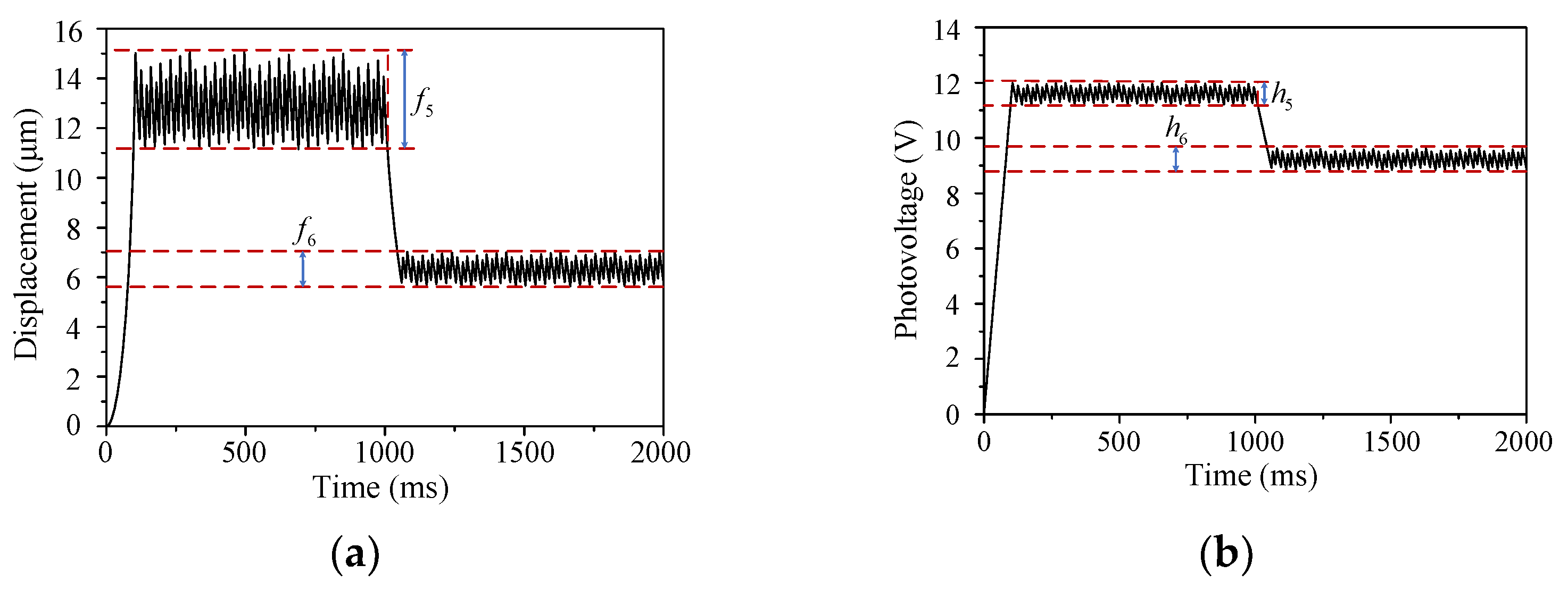
(2)
The maximal fluctuation heights around target displacement increase with the increase of the light intensity.
(3)
Under the same light intensity, the maximal fluctuation height around 12 μm is larger than around 6 μm. That is to say, the closer the output displacement is to the pull-in point, the more sensitive the displacement is to the change of driving voltage.

5. Conclusions

In this paper, the closed-loop displacement control of a novel photovoltaic-electrostatic hybrid actuator with a slant lower electrode based on the PLZT ceramic is proposed. The mathematical model of the photovoltage during the illumination and non-illumination phase and the mechanical model for the photovoltaic-electrostatic hybrid actuator is established. The driving performance of the photovoltaic-electrostatic actuator is studied through mathematical simulation. The results show that the displacement of the actuator can be controlled successfully at a particular value within the pull-in displacement by the light source, and the greater the light intensity is, the faster the displacement response of actuator can be obtained. Still, the control accuracy of the displacement becomes worse. Additionally, the closer the output displacement of the actuator to the pull-in point, the more sensitive the displacement is to the change of driving voltage. Hence, the photovoltaic-electrostatic hybrid actuator with a slant lower electrode based on the PLZT ceramic can be better designed, according to different practical applications.

Author Contributions

Conceptualization, Z.L.; methodology, Z.L. and X.W.; software, Z.L., Y.L. and M.U.; validation, M.U., Z.L. and X.W.; formal analysis, Z.L. and M.U.; investigation, Z.L.; resources, Z.L.; data curation, Z.L.; writing—original draft preparation, Z.L.; writing—review and editing, Z.L. and X.W.; visualization, X.W.; supervision, M.U. and X.W.; project administration, X.W.; funding acquisition, X.W. All authors have read and agreed to the published version of the manuscript.

Funding

This research was funded by the National Natural Science Foundation of China, grant number 52075263 and 51675282.

Institutional Review Board Statement

Not applicable.

Informed Consent Statement

Not applicable.

Data Availability Statement

Not applicable.

Acknowledgments

The authors gratefully acknowledge the funding support from the National Natural Science Foundation of China (No. 52075263 and No. 51675282).

Conflicts of Interest

The authors declare no conflict of interest. The funders had no role in the design of the study; in the collection, analyses or interpretation of the data; in the writing of the manuscript or in the decision to publish the results.

References

  1. Hubbard, N.B.; Culpepper, M.L.; Howell, L.L. Actuators for Micropositioners and Nanopositioners. Appl. Mech. Rev. 2006, 59, 324–334. [Google Scholar] [CrossRef]
  2. Mozhdehi, R.J.; Ghafari, A.S.; Khayyat, A.A.A. Design of electrostatic actuators for suppressing vertical disturbances of CMOS-MEMS capacitive force sensors in bio applications. Mech. Ind. 2015, 16, 306. [Google Scholar] [CrossRef]
  3. Brody, P.S. Optomechanical bimorph actuator. Ferroelectrics 1983, 50, 27–32. [Google Scholar] [CrossRef]
  4. Yue, H.H.; Sun, G.L.; Deng, Z.Q. Distributed shell control with a new multi-DOF photostrictive actuator design. J. Sound Vib. 2010, 329, 3647–3659. [Google Scholar] [CrossRef]
  5. Jiang, J.; Yue, H.H.; Deng, Z.Q. Active vibration control of an open cylindrical shell based on a 0-3 polarized PLZT photostrictive actuator. J. Vib. Shock. 2013, 32, 106–111. [Google Scholar]
  6. Zheng, S.J.; Lian, J.J.; Wang, H.T. Genetic algorithm based wireless vibration control of multiple modal for a beam by using photostrictive actuators. Appl. Math. Model. 2014, 38, 437–450. [Google Scholar]
  7. He, R.; Zheng, S.; Tong, L. Multimodal vibration control of photo-electric laminated thin cylindrical shells via self-organizing fuzzy sliding mode control. J. Vib. Acoust. 2016, 138, 041003. [Google Scholar] [CrossRef]
  8. Kikuchi, S.; Takagi, K.; Watanabe, R. Photostrictive characteristics of fine-grained plzt ceramics derived from mechanically alloyed powder. J. Jpn. Soc. Powder Powder Metall. 2004, 50, 572–576. [Google Scholar] [CrossRef]
  9. Lu, F.; Wang, X.J.; Huang, J.H. Theoretical and experimental analysis of an optical driven servo system. Smart Mater. Struct. 2016, 25, 095054. [Google Scholar] [CrossRef]
  10. Wang, X.J.; Huang, J.H.; Wang, J. Experimental research on the response characteristics of PLZT ceramics. Smart Mater. Struct. 2015, 24, 75017. [Google Scholar] [CrossRef]
  11. Huang, J.H.; Wang, X.J.; Wang, J. A mathematical model for predicting photo-induced voltage and photostriction of PLZT with coupled multi-physics fields and its application. Smart Mater. Struct. 2016, 25, 025002. [Google Scholar] [CrossRef]
  12. Jiang, J.; Li, X.; Ding, J. Mathematical model and characteristic analysis of hybrid photovoltaic/piezoelectric actuation mechanism. Smart Mater. Struct. 2016, 25, 125021. [Google Scholar] [CrossRef]
  13. Wang, X.J.; Lu, F.; Qiao, K. Closed-loop control for deflection of cantilever beam based on hybrid photovoltaic/piezoelectric actuation mechanism. Int. J. Appl. Electromagn. Mech. 2016, 53, 1–13. [Google Scholar] [CrossRef]
  14. Liu, Y.F.; Wang, X.J.; Wang, J. Investigation on influence factors of opto-electrostatic hybrid driving torsion actuator based on PLZT ceramic. Mater. Sci. Eng. B 2021, 263, 114798. [Google Scholar] [CrossRef]
  15. Wang, X.J.; Lu, F.; Huang, J.H. Closed-loop photovoltage control of lead lanthanum zirconate titanate ceramic for photovoltaic-electrostatic-driven servo system. J. Intell. Mater. Syst. Struct. 2017, 28, 2572–2578. [Google Scholar] [CrossRef]
  16. Huang, J.H.; Wang, X.J.; Wang, J. A study on residual photovoltage and photo-induced strain in plzt ceramic with coupled multi-physics fields. In Proceedings of the ASME 2015 International Mechanical Engineering Congress and Exposition, Houston, TX, USA, 13 November 2015. [Google Scholar]
  17. Fridkin, V.M. Photoferroelectrics; Springer: New York, NY, USA, 1979. [Google Scholar]
Figure 1. Schematic diagram of the photovoltaic-electrostatic hybrid actuator with a slant lower electrode. (a) The structure parameters of the actuator. (b) Force condition of the actuator.
Actuators 10 00285 g001
Figure 2. The coupling relationship of opto-electric-thermo-mechanic fields of PLZT ceramic.
Actuators 10 00285 g002
Figure 3. Time history of the photovoltage of PLZT under irradiation of different light intensities.
Actuators 10 00285 g003
Figure 4. The experimental and fitting curves of the photovoltage of PLZT ceramic under irradiation of different light intensities. (a) Light intensity is 20 mW/cm2. (b) Light intensity is 40 mW/cm2. (c) Light intensity is 60 mW/cm2.
Actuators 10 00285 g004
Figure 5. The flow sheet for the closed-loop displacement control of the hybrid actuator.
Actuators 10 00285 g005
Figure 6. Relation between displacement of upper electrode tip and torque under different driving voltage.
Actuators 10 00285 g006
Figure 7. The closed-loop control simulation curve of photovoltaic-electrostatic hybrid actuator illuminated by light intensity of 20 mW/cm2. (a) Time history of displacement. (b) Time history of photovoltage.
Actuators 10 00285 g007
Figure 8. The closed-loop control simulation curve of photovoltaic-electrostatic hybrid actuator illuminated by light intensity of 40 mW/cm2. (a) Time history of displacement. (b) Time history of photovoltage.
Actuators 10 00285 g008
Figure 9. The closed-loop control simulation curve of photovoltaic-electrostatic hybrid actuator illuminated by light intensity of 60 mW/cm2. (a) Time history of displacement. (b) Time history of photovoltage.
Actuators 10 00285 g009
Table 1. The structure parameters of the photovoltaic-electrostatic hybrid actuator.
ParametersValue
Width of the torsion beam (w1)10 μm
Thickness of the torsion beam (b)10 μm
Length of the upper electrode (l)1600 μm
Width of the upper electrode (w)900 μm
Maximum distance between the two electrodes (h)50 μm
Length of the torsion beam (l1)800 μm
Slant angle of the lower electrode (θ0)1.6°
Table 2. The fitting values of the identified parameters.
Light Intensity (mW/cm2)Parameter
VSτV0A1A2τd1τd2
20694.352013.06349.00431522.1006684.55887.198644.8564
40908.320910.75380.02662140.1163919.96578.673343.7224
601127.75539.8232−18.36231239.88182096.677242.42859.4857
Table 3. The driving performance of photovoltaic-electrostatic hybrid actuator.
Light IntensityResponse TimeMaximal Fluctuation Height around 12 μmMaximal Fluctuation Height around 12 μm
20 (mW/cm2)220 ms1.6 μm0.8 μm
40 (mW/cm2)140 ms2.9 μm1.1 μm
60 (mW/cm2)100 ms4 μm1.5 μm
Publisher’s Note: MDPI stays neutral with regard to jurisdictional claims in published maps and institutional affiliations.

