Article

A Novel Double Redundant Brake-by-Wire System for High Automation Driving Safety: Design, Optimization and Experimental Validation

1
State Key Laboratory of Automotive Safety and Energy, Tsinghua University, Beijing 100084, China
2
School of Vehicle and Mobility, Tsinghua University, Beijing 100084, China
3
Zhejiang Asia-Pacific Mechanical & Electronic Co., Ltd., Hangzhou 311203, China
*
Author to whom correspondence should be addressed.
Actuators 2021, 10(11), 287; https://doi.org/10.3390/act10110287
Submission received: 6 September 2021 / Revised: 19 October 2021 / Accepted: 21 October 2021 / Published: 26 October 2021
(This article belongs to the Section Actuators for Land Transport)

Abstract

:
The high redundant brake-by-wire system reveals vehicular safety handling ability and rarely emerges in the automotive area at the present time. This paper presents a novel brake-by-wire system, DREHB (Double Redundant Electro-Hydraulic Brake), with extensible fail-safe operations for high-automation autonomous driving vehicles. The DREHB is designed as a decoupled-architecture system containing three-layer cascaded modules, including a hydraulic power provider, a hydraulic flow switcher, and a hydraulic pressure modulator, and each of the modules can share dual redundancy. The operating principles of the DREHB in normal and degraded initiative braking modes are introduced, especially for the consideration of fail-safe and fail-operational functions. The matching and optimization of selected key parameters of the electric boost master cylinder and the linear solenoid valve were conducted using computer-aided batched simulations with a DREHB system modeled in MATLAB/Simulink and AMESim. The prototype of the DREHB was tested in hardware-in-the-loop experiments. The test results of typical braking scenarios verify the feasibility and effectiveness of the DREHB system, and the hydraulic pressure response as 28.0 MPa/s and tracking error within 0.15 MPa and the desirable fail-safe braking ability fully meets the requirements of higher braking safety and efficiency.

1. Introduction

In the past few decades, the energy crisis and air pollution have forced the automotive industry to turn to the development pathway of electrification [1]. Various hybrid and electric vehicles have gained the public’s attention due to their advantages in high efficiency and clean emissions. Recently, as the communication, artificial intelligence, and information fields have been rising, innovative technologies in autonomous driving have emerged subsequently [2,3]. Autonomous electric vehicles are up-and-coming to cope with the growing demands of traffic efficiency, environmental protection, and energy dilemmas. The advancements of electrification and automation put forward new requirements for vehicular braking systems to attain regenerative braking, automatic emergency braking, and other complicated and diverse braking functions [4,5,6].
Compared with the traditional braking systems, the brake-by-wire (BBW) system applied to autonomous electric vehicles must have an active braking capability. The BBW system is an electronic control system that replaces mechanical and hydraulic connections with wires and electric actuators, converting braking pedal commands from the driver into electronic signals that are to be processed via the in-vehicle communication network, thereby generating control signals to promote the electromechanical actuators for the desired operation. The decoupled systematic scheme of the BBW system is applicable to achieve regenerative braking, wheel slip control, and vehicle stability control, etc. Whether in the mature L2 level ADAS (Advanced Driver Assistance System) or advanced driverless-support automation level (L3, L4, and L5) [7], the brake-by-wire system is necessary for vehicular motion control. When the braking system fails, it must possess fault tolerance and redundant backup for safety consideration. The L3 level requires the driver to maintain the control authority of the vehicle, while the L4 and L5 do not require the driver to take over the vehicle in the whole driving course, thus the braking system must have the fail-safe and fail-operational abilities [7,8]. The brake-by-wire system with a sufficient redundancy design is the prerequisite to ensure the driving safety of high-level autonomous vehicles.
According to the forms of the hydraulic power source and the hydraulic pressure regulator, the present brake-by-wire systems can be classified into the following two categories: (1) “motorized pump-based accumulator + solenoid valves”; (2) “electric boost hydraulic cylinder”.
The SBC (Sensotronic Brake Control) developed by Bosch is representative of the former brake-by-wire system type [9]. The SBC uses an electrical high-pressure accumulator to load brake fluid. Assembled linear solenoid valves improve the control accuracy of the wheel cylinder pressure, but the cost is high compared to the on/off valves. The isolation piston inside the front wheel cylinder is set to ensure braking redundancy after the failure of the high-pressure accumulator. Once the high-pressure source fails, it can be switched to the driver’s control to retain the ability to brake on the front wheels.
Similarly, the ECB (Electronically Controlled Brake) developed by ADVICS is upgraded with four generations [10]. The ECB has a more complex mechanical structure in the master cylinder for generating hydraulic brake power. The hydraulic boost braking function is executed through the coordinated control of the high-pressure accumulator and the solenoid valves, and the fail-safe backup is guaranteed by the driver as well.
Although SBC and ECB systems have benefits in hydraulic pressure control, both schemes have a single hydraulic power supply unit. Once the high-pressure source fails, it can only rely on the driver’s strength to actuate the brake.
TRW’s SCB (Slip Control Boost) is based on two parallel-structured master cylinders, and a three-position three-way solenoid valve acts as the core role for operating pattern management [11]. The SCB system can offer switching and proportional control of the hydraulic pressure. The front and rear wheels are controlled by the completely decoupled four-way valves to regulate the wheel pressure. Likewise, only the front wheels can be in used for braking failure protection.
Among the three typical brake-by-wire systems mentioned above, SBC caused recall events due to the reduced braking efficiency in practical applications. The systematic composition of SCB is complicated along with huge size; also, the components are vulnerable to long-term usage. Only the Toyota motor holds a leading position in the “motorized pump-based accumulator + solenoid valves” typed brake-by-wire system.
The enriched dynamic performance and lightweight parts accelerate the “electric boost hydraulic cylinder” typed brake-by-wire systems to become the technical mainstream taken by most automotive companies. The iBooster, proposed by Bosch, converts the rotary motion of the boost motor into the linear motion of the pushrod to promote the master cylinder [12]. Even if the driver does not make a braking temptation on the brake pedal, iBooster can receive braking commands from VCU (Vehicle Control Unit); therefore, it can be fit with the autonomous driving control system well.
The boost motor in iBooster not only amplifies the driver’s foot braking force and pushes the master cylinder piston, but also provides pedal feedback to the driver. Moreover, the brush-less motor also assumes a pedal simulator. The boosting characteristics of iBooster can be adjusted to comply with the driver’s braking needs. Moreover, the active supercharging capability of an ESP (Electronic Stability Program) can ensure the active braking for the vehicle when iBooster fails [13]. However, the ESP’s active boosting and long-term pressure holding functions are limited in a few seconds and are not suitable for ordinary braking tasks.
Nissan’s e-ACT follows the same design philosophy to coordinate the electric master cylinder with the vehicle dynamics control unit [14]. Due to the large size of the separated electric booster and the electronic stability unit as well as the complicated coordination control strategy, some manufacturers have proposed the idea of integrating the two modules.
For example, the IBS (Integrated Brake System) designed by the LSP gives full play to the advantages of fast and precise control performance of motorization [15]. An additional pedal feel simulator is necessary in the braking system. The motor needs accurate position control as the core actuator in the whole brake-by-wire system continuously regulates the hydraulic pressure in the wheel cylinders.
In light of the above technical applications, Continental’s MK C1 and ZF’s IBC integrate the master cylinder, passive pedal feel simulator, and hydraulic modulation units into a weight-saving one-box design [16,17]. Four isolation solenoid valves decouple the brake pedal and the wheel cylinders. An auxiliary hydraulic cylinder is used as the high-pressure hydraulic source, and the eight pressure regulating valves are controlled for wheel cylinders. The structure of MKC1 is compact and lightweight, but the fail-operational functions are limited in turn.
In addition, the variant configurations of the brake-by-wire systems have also been designed. Honda’s ESB is equipped with two separated master cylinders and the independent hydraulic pressure modulation components, especially for the traditional ABS or ESC modules [18]. This arrangement reduces the difficulty of the subsystems’ integration, then the main and auxiliary cylinders are tandem double-chamber style.
Brembo has developed a composite brake-by-wire system [19]. The front axle takes an electro-hydraulic brake system, and the rear axle adopts an electro-mechanical brake system. Although the cost of the brake-by-wire system is relatively high, the operational failure backup mechanism is sufficient, and it has the potential for high-level autonomous driving.
The existing brake-by-wire systems mostly suffer from an insufficient braking redundancy design, and high-reliability braking capability for autonomous driving cannot be guaranteed. For this reason, termed as a ‘redundancy brake-by-wire system’, the system has to be designed to activate the vehicle’s emergency and consistency brake, even if the brakes are not activated due to electrical or mechanical failures or external shocks.
On the basis of the introduction on the development of the brake-by-wire systems, this paper proposes a novel decoupled electro-hydraulic brake system, featured with a double redundant backup with dual hydraulic power sources and hydraulic pressure-regulating units. The cascade linear solenoid valves are arranged at the same time. With multiple complementarities in terms of designed structure, the proposed DREHB can handle the fail-backup of brake functions in multiple failures, thereby ensuring the driving safety of high-level autonomous vehicles.
Centered on the development process of the DREHB, the rest of the paper is organized as follows. The mechanical-electro-hydraulic system configuration is outlined in Section 2 and the operating principles in different working modes are presented in Section 3. The parameter matching, optimization, and simulation of the proposed DREHB are described in detail in Section 4. Section 5 shows the manufactured prototype of the DREHB system, while providing the experimental results of the hardware-in-loop tests in typical braking scenarios. The concluding remarks are drawn in Section 6.

2. System Configuration Design

The primary function of the brake-by-wire system is initiative brake (IB) [20]. The high safety baseline of autonomous electric vehicles requires that the braking system must be able to provide sufficient redundancy in the event of mechanical, electrical, or communication failures. The remaining backup scheme is also called function degradation (FD) [21] and claims that the hydraulic braking forces of the wheel cylinders should not exhibit significant performance degradation when the braking capacity is degraded. Therefore, it is necessary to search the solution from two perspectives of the overall configuration of the brake system and the key functional components. In order to implement the initiative braking and redundant braking functions, a double redundant brake-by-wire system called a DREHB is proposed.
The configuration of the DREHB is shown schematically in Figure 1. The system is composed of three layers, namely the hydraulic power provider (denoted as P1, P2), the hydraulic flow switcher (denoted as S), and the hydraulic pressure modulator (denoted as M1, M2). At the bottom of the figure, there are four-wheel cylinders, abbreviated as LF, RF, LR, and RR for the left/right and front/rear locations.
The first layer is the hydraulic power provider. The two kinds of hydraulic power providers include an electric boost master cylinder (EBMC, denoted as P1) and an electric high-pressure accumulator (EHPA, denoted as P2). A boost motor with a gear box takes the role of vacuum booster in a conventional vehicle to promote the master cylinder. Considering that conditional automation (L3 level) in high-level autonomous driving still needs the driver to take over the control of vehicle braking in an emergency case, the brake pedal is retained. At the same time, the boost motor undertakes the functions of brake boosting and pedal feel feedback. The EBMC, composed of a plunger pump with an electric motor, a high-pressure accumulator, and other fitments, not only acts as the hydraulic power source, but also has the ability to regulate the hydraulic pressure. The EHPA cooperates with several solenoid valves to adjust the hydraulic pressure in wheel cylinders.
The second layer is the hydraulic flow switcher (denoted as S). Different operating modes of the DREHB are managed by the direction control function of the switching valves in this layer. In order to decouple the four-way wheel cylinders completely, four pairs of three-way valves (TwVs) and four-way valves (FwVs) are utilized here. Due to the large size of the switching valve, if the chassis layout is sensitive about the space limitations, it can also be simplified into two pairs of three-way valves and four-way valves, which are responsible for the two-wheel cylinders on the front axle and the two-wheel cylinders on the rear axle. In addition, the responsiveness of the switching valves and the reliability of long-term energization are also critical. The switching valve can achieve reliable fluid flowing because of the two-position mechanism; therefore, even if it fails, it can continue to provide brake fluid in the other direction.
The third layer is the hydraulic pressure modulator. Considering the precision requirements of hydraulic pressure regulation, the linear solenoid valves (LSVs, denoted as M2) are adopted in the DREHB underlying portion. The valves are optimized based on the high-speed on-off valves and can achieve linear pressure regulation by being controlled in a coil current. In addition, it should be noted that the electric boost master cylinder not only belongs to the hydraulic power provider, but also serves as another hydraulic pressure modulator (denoted as M1). Moreover, due to the particularity of the linear solenoid valve, in the event of a failure case, the inlet valve (IV) and outlet valve (OV) can be changed by the electronic control command to take over the control of the outlet valve or inlet valve conversely.
The DREHB is equipped with a pedal displacement sensor, a motor rotation angle sensor, a master cylinder pressure sensor, four-wheel cylinder pressure sensors, and an accumulator pressure sensor. If the driver participates in the braking operation, the pedal displacement signal given by the pedal displacement sensor reflects the braking expectation of the whole vehicle, and the master cylinder pressure sensor can be used as the failure backup. If there is no driver participation in the braking operation, the auto-driving vehicle control unit (VCU) sends out braking requests to the brake control units (BCU1, BCU2). The BCU1 and BCU2 combined with all the sensors accomplish the closed-loop control of the various braking functions.
The two brake controllers, BCU1 and BCU2, are used as a mutual backup in the DREHB system. BCU1 is mainly responsible for controlling the electric boost master cylinder with LSVs, and BCU2 is for controlling the electric high-pressure accumulator with LSVs. Under the control of BCU1 and BCU2, regardless of whether the DREHB system is in a normal state or a failure state, the DREHB system operates steadily in initiative braking functions including electronic braking force distribution, regenerative braking, automatic emergency braking, anti-lock braking, yaw stability control, etc.

3. System Operation Principles

As the DREHB system has the characteristics of dual redundancy backup and has many controllable components, the topological operational modes are more diverse. For the convenience of presentation, the operational modes under normal initiative braking (NIB) and degraded initiative braking (DIB) conditions are, respectively, introduced in the following context.

3.1. Normal Initiative Braking Modes

The normal initiative braking modes are classified according to the working status of hydraulic power providers. From the perspective of the hydraulic supply, the DREHB working modes can be subdivided into the following three types: a single electric boost master cylinder, a single electric high-pressure accumulator, and both of the two providers. The working modes of the DREHB operating under NIB are shown in Figure 2.

3.1.1. NIB A Mode

When the DREHB is in the working mode, as in Figure 2a, the electric boost master cylinder provides the hydraulic supply and pressure regulation solely. The states of the switching valves are shown in detail, while the linear solenoid valves remain in normal states. Only the EBMC assumes the function of adjusting the pressure of the wheel cylinders; therefore, the independent control of the four-wheel braking forces cannot be achieved. This working mode is suitable for braking conditions that do not require high accuracy of the four-wheel pressure control, such as adaptive cruise control (ACC) [22]. At this time, the EHPA is in the standby state, and the high-pressure accumulator is filled with high-pressure brake fluid.

3.1.2. NIB B Mode

Likewise, when the DREHB system is in the working mode, as shown in Figure 2b, the EHPA provides the hydraulic supply of the four-wheel cylinder solely, and the linear solenoid valves are responsible for the hydraulic pressure regulation of four-wheel cylinders. The three-way and four-way switching valves are energized. The normally closed valves (CV) are used for inlet valves, while normally open valves (OV) are used for outlet valves. If the driver steps on the brake pedal, the boost motor still needs to perform brake boosting, and the pedal feel is fed back to the driver. If the VCU sends out braking requests, the EBMC subsystem maintains the standby state.

3.1.3. NIB C Mode

When the DREHB is in the working mode, as shown in Figure 2c, the EBMC and EHPA supply hydraulic power collectively. Additionally, there are multiple possible working modes here, which can be categorized into (1) the EBMC undertakes one channel of wheel brakes, and the other three channels are dependent on the EHPA; (2) the EBMC undertakes two channels of wheel brakes, and the other two channels are dependent on the EHPA; likewise, (3) the EBMC is for three-channel wheel brakes, and the remaining channel is working with the EHPA. As an example, in Figure 2c, the wheel cylinders of the front axle are governed by the EBMC in hydraulic supply and pressure regulation, and the rear-axle wheel cylinders are supplied by the EHPA and regulated by LSVs under hydraulic pressure.

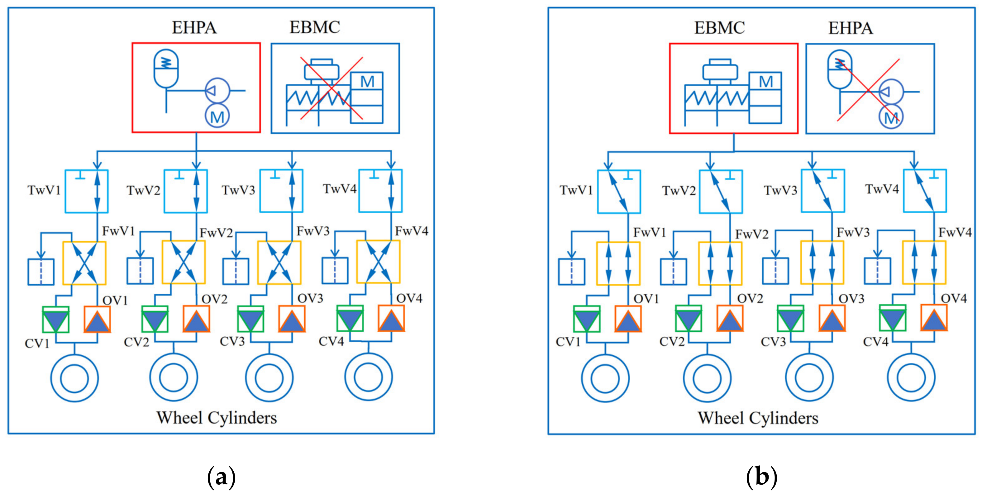
3.2. Degraded Initiative Braking Modes

The DREHB system has a number of fundamental components. When some components fail in the redundant working modes, the DREHB controller can replan a new topology regarding the requirements of the vehicle and the remaining healthy braking system. Therefore, the redundant operating modes of the DREHB system are subdivided according to the failures of the key functional components at each level.

3.2.1. DIB F1 Modes

Mode A: As shown in Figure 3a, when the boost motor fails, the EBMC cannot normally provide hydraulic power to the master cylinder. In this case, the hydraulic power supply is taken over by the EHPA, and the hydraulic pressure of the four-wheel cylinders can be adjusted independently by LSVs.
Mode B: As shown in Figure 3b, when the pumping motor fails, the EHPA cannot normally provide hydraulic power to the high-pressure accumulator. In this case, the hydraulic power supply and pressure regulation of the four-wheel cylinders are all undertaken by the EBMC.

3.2.2. DIB F2 Modes

Mode A: As shown in Figure 4a, when a three-way valve fails, the upstream hydraulic power source can only be aligned to one of the EBMC and EHPA. If the hydraulic power source is selected with the high-pressure accumulator, the wheel cylinder pressure is adjusted independently through the corresponding linear solenoid valve; if it is the EBMC, the wheel cylinder pressure is independently supplied and adjusted.
Mode B: As shown in Figure 4b, when a four-way valve fails, the downstream linear solenoid valve can only achieve the function of a normally open valve (OV) with the pressure increasing or a normally closed valve (CV) with the pressure increasing. At this time, the three-way valve of this channel is coordinated correspondingly, no matter which hydraulic power source is chosen.

3.2.3. DIB F3 Modes

Mode A: As shown in Figure 5a, if a certain channel of the normally closed valve (CV) fails, only the normally open valve (here, OV is used as the inlet valve) of the same channel can be controlled at this time; therefore, the EBMC is selected as the hydraulic power source unit.
Mode B: As shown in Figure 5b, if a certain channel of the normally open valve (OV) fails, only the normally closed valve (here, CV is used as the inlet valve) of the same channel can be controlled at this time. Meanwhile, the EBMC is selected as a pressure supply unit as well.
In addition, other redundant operating modes are basically modified from the above three types of failure modes to be suitable for different braking requirements and will not be repeated here.

4. Parameter Matching and Optimization

The foundation of the high redundancy and high control performance of the DREHB system comes from the key functional components inside the braking system. Among them, the hydraulic power unit and the pressure regulating unit have a decisive influence on the performance of the DREHB system. For the sake of achieving high-performance hydraulic pressure in the brake-by-wire system, the most effective and direct way is redesigning the electro-mechanical actuators, and comprehensive studies on this topic have been carried out. Research has established analytical and nonlinear models of high-speed on-off valves, which consider the fluid and mechanical coupling and optimize the key factors to improve the feasibility through experiments [23,24]. Other researchers have been focused on the novel optimization methods and techniques about the mechanical problems with numerical models [25,26]. A parameter design of the key components in the DREHB is introduced in further detail below.

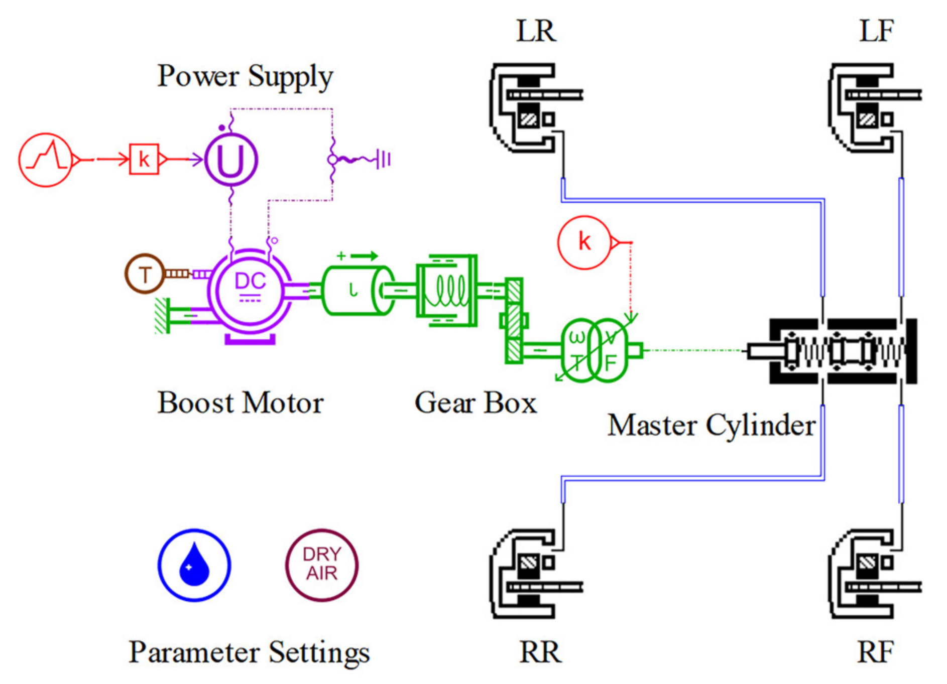
4.1. Electric Boost Master Cylinder

Research is carried out from the following two aspects: static analysis and dynamic simulation. The parameters of actuators in the EBMC that affect hydraulic response performance include motor torque, speed, gear ratio, master cylinder piston diameter, etc.

4.1.1. Static Performance with Primary Specification

In parameter matching, the performance specifications of the DREHB need to be determined first, then the static and dynamic models of the hydraulic brake system are established. The initially selected values of the static model parameters are brought into the dynamic model to test whether the performance demands are met. If they are, the optimization can proceed. If not, the parameters will continue to be adjusted until the performance demands are fulfilled.
In the conceptional designation mentioned above, the DREHB should ensure the hydraulic pressure capacity and the responding time of the increasing/decreasing pressure rate. The open-loop performance specifications of the EBMC are concluded in Table 1.
Depending on the conceptual components in the DREHB, the static system model of the EBMC with corresponding actuators should be built first for the primary preference of parameters. As depicted in Equations (1) and (2), the static force balance analysis on the push rod and cylinder piston of the DREHB reflects the fundamental mechanical relationships of the EBMC system [27].
T m 2 π η = F p l ,
F p = π d p 2 4 P ,
where T m is the output torque of the boost motor, η is the mechanical efficiency of the gear box, F p is the force applied on the push rod, l is the lead of the screw unit, d p is the diameter of piston, and P is the hydraulic pressure in the master cylinder.
The key parameters of the EBMC are selected primarily as follows: the diameter of piston d p is 24 mm, the transmission efficiency of gear box η is 0.95, and the lead of guide screw l is 5 mm. According to the open-loop performance specifications, the torque of the boost motor T m is calculated as 4.55 Nm when the expected maximum of hydraulic pressure is 12 MPa.
Generally, the manufacturer of the electric motor can provide the limited maximum no-load speed n m a x as an important aspect of the motor’s external characteristics. Here, n m a x is set to 2800 r/min. The voltage of battery power supply is 12.0 V.
The following are the assumptions made to design the motorization parameters [28]:
  • In the case of rotor locking, the motor speed is 0;
  • Under a no-load condition, the zero-load current is ignored;
  • Assume that the motor has no magnetic flux leakage.
The motorization relationships of the operating characteristics and eternal properties combined with the assumptions above are formulated in the following equations:
T m a x = U N / R m k t ,
ω m a x = U N / k b e ,
k b e = k t ,
where T m a x is the maximum stalling torque, U N is the power supply voltage, k b e and k t are the back EMF coefficient and torque coefficient, ω m a x is the maximum angular speed, and R m is the equivalent resistance.
According to the formulas above, the key parameters of boost motor are obtained with k b e = 4.1 × 10 2   V / rad / s and R m = 0.108   Ω .
The responding performance of the EBMC is determined by the motor inductance value. Compared with the electro-mechanical braking systems in the literature [29,30], the motor current response of the EBMC should be within the ± 5 % error range in 0.5 ms. As referred from the high-energy-density motor manual, the value selection of motor inductance is L m = 6.25 × 10 5   H .

4.1.2. Dynamic Simulation and Parameter Matching

The lengths of the brake pipe and hose between the DREHB and the brake cylinders are preliminarily estimated, and the essential parameters in the AMESim model are set according to Table 2 [31]. The P–V characteristics of the front and rear brakes used in the AMESim model refer to the commercial auto brake parts. The simulation is performed repeatedly, and the parameters are adjusted until the open-loop performance is up to the expected responses.
Figure 6 shows the dynamic model of the EBMC with the whole braking system. The exciting signal of the boost motor is a 12.0 V voltage input stepping up and down during a time range of 0.5 to 2.0 s. The gear box with equivalent inertia transfers the rotational motion into the translational motion of the master cylinder piston. The parameter settings of the EBMC in the dynamic model are all based on the mass production parts.
A number of parameter sets are batched here in the open-loop simulations. To reflect the critical influence on the dynamic response, the transmission ratio of the gear box, the diameter of the piston, and the travel displacement of the piston are chosen as the key factors. Figure 7 shows the open-loop simulation results of wheel cylinder pressure response among eight sets of batched parameters. The parameters used in the model are detailed in Table 3 below. It is obvious that the maximum pressure criteria with 12 MPa excludes the ParSet3/4/5/8, and the small transmission ratio cannot be adequate for high pressure generation. The fact can be drawn that the gear ratio increases the steady pressure amplitude and the step-excited pressure rising rate notably when comparing the response results of the batched diameters and travel displacements of the piston. From the pressure response curve of ParSet6, the highest steady pressure is 16.7 MPa with the slower decreasing pressure slope. Furthermore, in light of ParSet1/2/7, similar pressure results within the open-loop performance demands are obtained. Due to the national standard parts and manufacturing restrictions of the existing master cylinder assembly involving the diameter and travel displacement of the piston, the more flexible way is to alternate the gear ratio greatly to obtain a better pressure response and more universal adaptability in automotive applications. Moreover, considering the motor capacity and the proper mechanical abrasion with lower gear ratio and smaller piston size, the ParSet7 of the EBMC is chosen for the final key parameters’ designation values.
Several of the engineering development steps of this paper are not described, while listed as follows:
  • Component selection, engineering drawing design, and strength check;
  • Electronic control unit development;
  • Digital simulation and development.

4.2. Linear Solenoid Valve

In the automotive hydraulic brake control system, the brake pressure generated by the hydraulic power source must be modulated by the electromagnetic valves to enter the wheel cylinders, and finally, braking forces are produced. On the basis of working conditions and performance requirements, the core mechanical and electrical parameters are redesigned for linear solenoid valves based on the widely used high-speed on/off valves [32].

4.2.1. Parameter Optimization of Mechanical Valve

The flow characteristics of the solenoid valve are strongly determined by the structural parameters. The design goal is that under the initial pressure at 15 MPa of the high-pressure accumulator, the step response time of the wheel cylinder pressure at 10 MPa should be less than 220 ms. The key structural parameters of the solenoid valve are specifically designed below. A geometric structure diagram of the solenoid valve with a cone seat and ball core is shown in Figure 8 [33].
As shown in Figure 9, a solenoid valve model is built by MATLAB/Simulink to demonstrate the mechanical dynamics. The fundamental of the mechanical–hydraulic–electrical coupled relationship is expressed in Equation (6).
m d 2 x v d 2 t = F e + F s + F h F B ,
where m represents the total mass of the moving iron, spool, and pushrod; x v is the displacement of the spool; F e is the electromagnetic force; F s is the spring force; F h is the hydraulic force; and F B is the damping force. The full expressions of the forces above are found in paper [34].
The valve body, as the core section of the solenoid valve, is composed of the valve core, return spring, valve seat, etc. The design of the solenoid valve body is directly related to the control accuracy of the braking force and the rapid pressurization. The main design parameters of the solenoid valve body include the mass of the spool, the stiffness of the return spring, the cone angle of the solenoid valve seat, and the diameter of the steel ball. The PWM (Pulse Width Modulation) signal of the controllable voltage source acts on the coil to produce an equivalent current via electrodynamics. Among these parameters, the diameter of the steel ball and the seat angle mainly affect the flow rate of the solenoid valve through the orifice throttling effect. Therefore, the batched values of the diameter of the ball core and the valve seat angle with PWM signals are set in the Simulink model. The simulation results are concluded in Figure 10 and parameter sets are shown in Table 4.
From the hydraulic pressure response curve results, it can be seen that the flow characteristics of the linear solenoid valve are mostly related to the diameter of the steel ball in a certain range between 1.5 and 2.4 mm and seat semi-angle from 47° to 52°. Additionally, the pressure saturation phenomenon is evident near the upper and lower bounded values. The parameter sets ParSet7 and PatSet8 are not suitable for the valve ball design because the time response from 0 to 10 MPa is out of 220 ms, while the results of ParSet5/6/7 give out the fact that with a bigger valvelet diameter comes a faster pressure response in the wheel cylinders. Furthermore, the hydraulic pressure responses are obviously saturated in the area from ParSet1 to ParSet4. However, increasing the mass of the spool and valvelet mainly affects the acceleration of the solenoid valve when it moves, and then this may cause severer vibration. According to the simulation results, the diameter of the steel ball is taken as 2.0 mm, which not only improves the pressure response speed, but also better matches the commonly used 50° seat hole as well as reducing the size of the valve body. Therefore, the parameter set ParSet4 is the more reasonable choice in the LSV’s mechanical optimization design case.

4.2.2. Parameter Optimization of Electrical Coil

Compared with the traditional ABS and ESC in the automotive industry, the operating frequency of the DREHB solenoid valve has changed to an extremely high probability for normal operations. The drive force of the high-frequency solenoid valve comes from the coil on the top of the solenoid valve. The electromagnetic characteristics of the LSV play an indispensable part in the dynamic behavior of the valvelet dynamics [35]. The current through the solenoid coil generates a magnetic field to push the valvelet actively to control the flow rate. In the midst of the electrical parameters that affect the electromagnetic characteristics of an LSV, it is quite comprehensible that more turns of coil windings will generate a larger electromagnetic force to drive the valvelet. The research [36] indicates that a smoother coil current can result in a better performance in the controllability of the LSV. Hence, the turn number and the coil current of coil windings are selected to be investigated for the optimal electrical parameter set of the LSV.
Based on the aforementioned electromagnetism principles, a dynamic LSV with a thorough electrical coil was modeled in AMESim, as shown in Figure 11. The basic elements of drive circuit, air gap, rectifier diode, capacitor, and return spring were used to establish the coil and valve models. The pre-compression of the spring connected with the valvelet mass was used to act as the valve mechanics. The drive circuit of the coil produced the 700 Hz PWM signal, and the battery voltage was 12 V. Six different sets of turn numbers and duty cycles of PWM signals were chosen for the batched simulations. The coil current was selected as the measured physical quantity, and the simulation results are shown in Figure 12.
From the coil current response curves, under a certain increasing range of two parameters, the smoothness of the coil current increased significantly when the turn number of coil windings varied from 420 to 750 and PWM duty ranged from 60% to 80%, which declares that the LSV can be controlled with a relatively steady current signal, and the inductance impedance will cause less Joule heating effect. A longer duration is preferred for the LSV in operating mode, especially when there is the long time braking or traffic congestion dilemma. However, further increasing the turns of the coil windings would cause an oversized coil, which is unfriendly to assemble in the limited space of the hydraulic control unit, and deteriorate the heat radiation. When the turn number was 700 and PWM basic duty was 75%, the current wave of coil fluctuated more evenly, which is suitably matched with the control logic cycle period of BCU as 10 ms. Therefore, the electrical parameter set ParSet5 is feasible and adopted in the LSV coil design of the DREHB. The batched electrical parameter sets in simulations are listed in Table 5.
Through the above-mentioned theoretical analysis and simulation research, the design of the core components in the DREHB was completed. The experimental validation was carried out next.

5. Experimental Verification and Discussion

To verify the feasibility and effectiveness of the proposed DREHB system in brake-by-wire applications, the manufactured prototype of the DREHB and other hydraulic braking accessories make up the hardware-in-loop (HIL) testbench. Typical braking scenarios are set for the dynamic performance validation of the EBMC and the LSV designed in the foregoing context.

5.1. Prototype of the DREHB System

A trial-manufactured DREHB system and four-wheel cylinders are combined together in Figure 13. Note that the two braking control units BCU1 and BCU2 communicating with CAN (Controller Area Network) bus are dually equipped for the supervisory redundancy. The EBMC system corresponds to the sketched one in Figure 13, while the EHPA system is integrated with all the electromagnetic valves (EMVs, here are labeled for LSVs) in the mechanical structure. Hydraulic pipelines are used for the linkage between the EBMC, the EHPA, EMVs, and four-wheel cylinders.
As shown in Figure 13, the hardware-in-loop testbench is composed of the host computer, DC power supply, dSPACE AutoBox, and the designed components of the DREHB system. The host computer is utilized for monitoring the test experiments and data processing of the test results. The DC power supply is adopted as the 12 V constant voltage source. Acting as the VCU of the vehicle electronic control system, the dSPACE AutoBox bridges the communication connections between the BCU1, BCU2, and the host computer to exchange CAN bus information and transfers the controllers’ commands. The BCU1 is integrated together with the EBMC, and the BCU2 is united with the EHPA as well as the LSVs. The hydraulic sensors acquire the hydraulic pressure signals from the master and wheel cylinders and transmit the messages to the brake controllers and dSPACE AutoBox. To evaluate the human effect in the braking process and examine the initiative brake systems such as the DREHB proposed in this paper, the brake pedal unit is retained in the HIL test platform. The iBooster and ESP are also incorporated in the HIL system for the experimental comparison.

5.2. Experimental Tests in Typical Braking Scenarios

Three braking scenarios were set for the dynamic performance validation of the parameter design of the EBMC and the LSV on the HIL test platform shown in Figure 13. The first one was the combination of continuous steps up and down of open-loop excitation for the master cylinder piston target. The second one was the sinusoidal target pressure tracking of wheel cylinders by modulating the LSVs in a close-loop control [37]. The last one was set for the comparative validation of the fail-safe braking function of the DREHB.

5.2.1. EBMC Braking Test

For autonomous electric vehicles, the critical braking demand in real-life driving cycles is the automatic emergency brake (AEB) function for the safety concern. In this case, the input signal was defined as the expected piston position x of the master cylinder, and the step signals up and down were assumed to be the continuous sudden brake in different intensity levels of AEB-liked scenarios. The HIL test results of the step wave input of the piston position are depicted in Figure 14.
For the AEB and ESP scenarios, the main concern of hydraulic pressure in the wheel cylinders is the swift build-up or drop-down response. The step wave input of the master cylinder piston started at 4.0 s and fell to the original position in 22.0 s. A single phase of step signal lasted for 2.0 s, and the sample time of the pedal travel sensor to the control unit was 0.001 s. The inner position control loop was well calibrated in the boost motor; therefore, the position response exhibited the lagging shape when the expected x was compared with the actual one. The minimum speed of the wheel cylinder pressure response was calculated as 28.0 MPa/s from the green curve, which means that AEB function activates in 250 ms to build a 7.0 MPA hydraulic pressure to lock the wheels. The response time of the traditional braking system with brake booster and ABS device was about 400–600 ms, because it does not have the function of active pressurization, and the response time of the wheel cylinder pressure contains the driver’s reactions. The time taken for the wheel cylinder pressure to increase from 0 to 7.0 MPa was about 350–1400 ms. Moreover, the widely used iBooster and ESP system achieved a 220-millisecond duration time to reach 10.0 MPa without adding the driver’s response time according to the reported test data [29]. Thus, the experimental results of step response of hydraulic pressure comply with the AEB-liked scenarios’ demands satisfactorily. There was a hydraulic pressure difference between the wheel cylinder pressure and the master cylinder pressure, and the reason lies in the hydrodynamic resistance existing in the DREHB system. In conclusion, the step response of the wheel cylinder pressure revealed the effectiveness of the designed EBMC with optimized electro-mechanical parameters in initiative braking scenarios such as the AEB condition.

5.2.2. LSVs Braking Test

For driving scenarios such as adaptive cruise control (ACC), the ego vehicle will follow the front vehicle by keeping an inner-car distance. That means, the ego vehicle has to accelerate or slowdown in time automatically and precisely. In this case, the autonomous electric vehicle takes the regenerative braking ability of the electric powertrain and distributes the braking forces between the power motor and the DREHB system. Thus, the wheel cylinder pressure must keep the fast and precise tracking performance in complex braking conditions. Moreover, the hydraulic pressure adjustment should be independent among four-wheel brakes to achieve the fully decoupling braking facility in case of anti-lock braking or other extreme braking tasks. Two sinusoidal wave signals were introduced for the front left (denoted by one) and rear left (denoted by three) wheel cylinders’ pressure targets simultaneously. The frequency of both sinusoidal waves was 1.0 Hz, and the average pressure value of the first one was 7.0 MPa, while the second one was 3.0 MPa. Pressure variation ranges of two sinusoidal waves were within 2.0 MPa. The test results are seen in Figure 15.
The LSVs are controlled with closed-loop PID (Proportional–Integral–Derivative) algorithms to track the sinusoidal pressure target signals. The PID calibration parameters used in the controllers of the OVs and CVs are listed in Table 6, where k P , k I , k D represent the control gains of PID controllers. The RMSE (Root Mean Square Error) values for both channels of wheel cylinders are also summed in the table.
The experimental results show that, at the beginning of the pressure tracking stage, the inlet valves opened as much as possible to reduce the error to tackle the target pressure. Thanks to the optimized turn number of coil windings, the rising time for two-wheel cylinders was 90 and 180 ms, respectively, reaching the sufficient response speed for extensive tasks of precise hydraulic pressure control. One obvious advantage in pressure tracking the LSVs was the lower overshoot, at less than 0.3 MPa, which resulted from the parameter optimization in the LSVs to obtain a better controllability. It was beneficial to mitigate the braking jerk condition for improving the vehicle drivability. During the whole pressure tracking process, the pressure error was within tight bounds, less than 0.15 MPa in either brake channel. In contrast, the reported hydraulic pressure modulation accuracy of iBooster and ESP was 0.2 MPa [32], and the pressure control effectiveness of the DREHB in this research was remarkably superior to the hydraulic control performance of the widely used BBW system, with a 25% accuracy improvement. It should be noted that the hydraulic pressure modulation error was highly related to the controllability of the actuators. Hence, the LSVs with closed-loop controllers were proven to have a satisfying performance in the consistent dynamic braking scenarios conclusively.

5.2.3. Fail-Safe Braking Test

The initiative brake system designed in this research is expected to enable high-safety braking ability, especially for the fail-safe braking scenarios. When a certain failure occurs in the DREHB, the degraded initiative braking modes described in Section 3.2 are dedicated to performing the fail-safe functions by managing the feasible operations among the EBMC, the EHPA and the LSVs. To validate the fault tolerant effectiveness and reliability of the DREHB, the comparative braking test was carried out by three brake systems responding in the scenario where emergency braking is incorporated with an undesirable fault injection. The IBS in the literature [36], the iBooster with an ESP, and the DREHB proposed in this work were chosen for the parallel experiments with the same scenario settings and control targets. The brake control strategy and hydraulic pressure regulation are based on the threshold logic and PID controllers in the Section 5.2.2. Moreover, the hydraulic control logic in the DREHB controller is reused in iBooster and ESP. The test results are shown in Figure 16.
The experimental scenario setting was the same as the reported one in [36]. Assuming that the vehicle encountered an emergency event at 5 s, the three brake systems triggered the automatic emergency brake simultaneously and the wheel pressure control targets held at 7 MPa similarly. It can be seen that similar response speeds are achieved but the DREHB revealed the lower pressure overshot in comparison with the iBooster and ESP, and that is because the driving capacity of boost motor in the DREHB is designed on account of a higher load margin, which gains the advantage of preferable controllability.
At 11.5 s, one solenoid coil burned accidentally, which caused a sudden decrease in the wheel pressure, tending to deteriorate the braking performance and endanger the vehicle collision avoidance. In the test case of IBS, the driver needed 500 ms–1 s to react during the pressure dropping stage, and after 0.5 s, the wheel pressure returned to 7 MPa by the driver’s effort with obvious braking degradation. By virtue of the fail-safe backup design in the other two brake systems, the time from fault detection to brake controller reaction could be reduced to 400 ms, and the faster electronic brake control recovered the pressure within 150 ms, which improved the restored wheel pressure response enormously. The supercharging was activated by the boost pump for the iBooster and ESP, but the huge overshot was 5 MPa and steady-state error occurred dramatically due to the poor pressurization controllability of the ESP in the limited boosting time. On the contrary, the pressure restoration of the DREHB was accomplished through the EHPA and LSVs. The EHPA provided sufficient hydraulic power around 7 MPa, and the optimized linear solenoid valves held the wheel pressure steadily, thus the pre-fault pressure state could be reestablished rapidly and precisely. Hence, the proposed DREHB exhibits an advancement in fail-safe braking function in comparative tests.

6. Conclusions

A novel double redundant brake-by-wire system for high automation driving safety was revealed in this article. The development process of the DREHB system, including the conceptual systematic configuration design, analysis of operational principles, parameter matching and optimization, and experimental validation, was introduced throughout the paper. The DREHB system consists of the following three functional layers: a hydraulic power provider, a hydraulic flow switcher, and a hydraulic pressure modulator, and each layer has a dual redundancy design. Accordingly, the braking controllers and mounted sensors are set for extra backup. The operational principles of the DREHB in normal and degraded initiative braking modes were brought out, and the potential adaptability of every configuration topology was shown. Parameter matching and optimization of the electric boost master cylinder (EBMC) and the linear solenoid valve (LSV) were conducted in theoretical derivation and simulation, and the dynamic hydraulic performance criteria were met exactly. In conclusion, the feasibility and effectiveness of the proposed DREHB system for high automation electric vehicle are verified by the manufactured DREHB system with the HIL test platform. The fast, steady, and precise hydraulic pressure control performances in commonly used driving scenarios including AEB, ACC, and fail-safe braking conditions prove the DREHB system to be practicable for the high safety demand of autonomous electric vehicles. In future work, the fail-operational function in real vehicle verification and redundant control strategy design of the proposed DREHB system are going to be further investigated.

Author Contributions

Conceptualization, C.L.; methodology, C.L. and X.H.; software, C.L. and Y.J.; validation, C.L. and J.H. (Jinheng Han); formal analysis, C.L. and X.H.; investigation, C.L., Y.J. and J.H. (Jinheng Han); resources, J.Z. and J.H. (Jiangmai Hao); data curation, C.L.; writing—original draft preparation, C.L.; writing—review and editing, C.L. and C.H.; visualization, C.L.; supervision, J.Z.; project administration, C.H.; funding acquisition, J.Z. All authors have read and agreed to the published version of the manuscript.

Funding

This research was funded by Key-Area Research and Development Program of Guangdong Province (Grant Number: 2019B090913001).

Institutional Review Board Statement

Not applicable.

Informed Consent Statement

Not applicable.

Data Availability Statement

Data sharing is not applicable to this article.

Conflicts of Interest

The authors declare no conflict of interest.

References

  1. Dia, H. Rethinking urban mobility: Unlocking the benefits of vehicle electrification. In Decarbonising the Built Environment; Palgrave Macmillan: Singapore, 2019; pp. 83–98. [Google Scholar]
  2. Mohan, A.; Sripad, S.; Vaishnav, P.; Viswanathan, V. Trade-offs between automation and light vehicle electrification. Nat. Energy 2020, 5, 543–549. [Google Scholar] [CrossRef]
  3. Levinson, J.; Askeland, J.; Becker, J.; Dolson, J.; Held, D.; Kammel, S.; Kolter, J.Z.; Langer, D.; Pink, O.; Pratt, V. Towards fully autonomous driving: Systems and algorithms. In Proceedings of the 2011 IEEE Intelligent Vehicles Symposium (IV), Baden-Baden, Germany, 5–9 June 2011; pp. 163–168. [Google Scholar]
  4. Guo, J.; Li, W.; Wang, J.; Luo, Y.; Li, K. Safe and Energy-Efficient Car-Following Control Strategy for Intelligent Electric Vehicles Considering Regenerative Braking. IEEE Trans. Intell. Transp. Syst. 2021. Early Access. [Google Scholar] [CrossRef]
  5. Schram, R.; Williams, A.; van Ratingen, M. Implementation of Autonomous Emergency Braking (AEB), the next step in Euro NCAP’S safety assessment. ESV Seoul 2013, 13-0269. [Google Scholar]
  6. Han, K.; Lee, B.; Choi, S.B. Development of an antilock brake system for electric vehicles without wheel slip and road friction information. IEEE Trans. Veh. Technol. 2019, 68, 5506–5517. [Google Scholar] [CrossRef]
  7. Hasan, S.; Balador, A.; Girs, S.; Uhlemann, E. Towards emergency braking as a fail-safe state in platooning: A simulative approach. In Proceedings of the 2019 IEEE 90th Vehicular Technology Conference (VTC2019-Fall), Honolulu, HI, USA, 22–25 September 2019; pp. 1–5. [Google Scholar]
  8. Jonasson, M.; Thor, M. Steering redundancy for self-driving vehicles using differential braking. Veh. Syst. Dyn. 2018, 56, 791–809. [Google Scholar] [CrossRef]
  9. Kant, B. Sensotronic brake control (SBC). In Automotive Mechatronics: Automotive Networking, Driving Stability Systems, Electronics; Reif, K., Ed.; Springer Fachmedien Wiesbaden: Wiesbaden, Germany, 2015; pp. 412–415. [Google Scholar]
  10. Soga, M.; Shimada, M.; Sakamoto, J.-I.; Otomo, A. Development of vehicle dynamics management system for hybrid vehicles: ECB system for improved environmental and vehicle dynamic performance. JSAE Rev. 2002, 23, 459–464. [Google Scholar] [CrossRef]
  11. Lubischer, F.; Pickenhahn, J.; Gessat, J.; Gilles, L. Fuel savings through steering and braking technologies. ATZ Worldw. 2008, 110, 26–32. [Google Scholar] [CrossRef]
  12. Fausten, M.; Huck, T.; Rühle, A.; Baysal, T.; Kornhaas, R. Automated driving-Impacts on the vehicle architecture. In Proceedings of the 2015 Symposium on VLSI Technology (VLSI Technology), Kyoto, Japan, 16–18 June 2015; pp. C28–C31. [Google Scholar]
  13. Kunz, A.; Kunz, M.; Vollert, H.; Förster, M. Electromechanical brake booster for all drive concepts and automated driving. ATZ Worldw. 2018, 120, 58–61. [Google Scholar] [CrossRef]
  14. Ohtani, Y.; Innami, T.; Obata, T.; Yamaguchi, T.; Kimura, T.; Oshima, T. Development of an Electrically-Driven Intelligent Brake Unit; 0148–7191; SAE Technical Paper: Warrendale, PA, USA, 2011. [Google Scholar]
  15. Leiber, T.; Köglsperger, C.; Unterfrauner, V. Modular brake system with integrated functionalities. ATZ Worldw. eMagazine 2011, 113, 20–25. [Google Scholar] [CrossRef]
  16. Feigel, H.-J. Integrated brake system without compromises in functionality. ATZ Worldw. 2012, 114, 46–50. [Google Scholar] [CrossRef]
  17. Meyer, M.; Milot, D. Lightweight and compact braking system for fast deceleration. ATZ Worldw. 2017, 119, 26–29. [Google Scholar] [CrossRef]
  18. Ohkubo, N.; Matsushita, S.; Ueno, M.; Akamine, K.; Hatano, K. Application of electric servo brake system to plug-in hybrid vehicle. SAE Int. J. Passeng. Cars-Electron. Electr. Syst. 2013, 6, 255–260. [Google Scholar] [CrossRef]
  19. Vrábel, J.; Jagelčák, J.; Rievaj, V.; Caban, J. The quality of the brake components and its impact on the basic parameters of braking. Mach. Technol. Mater. 2014, 8, 6–8. [Google Scholar]
  20. Soltani, A.; Bagheri, A.; Azadi, S. Integrated vehicle dynamics control using semi-active suspension and active braking systems. Proc. Inst. Mech. Eng. Part K J. Multi-Body Dyn. 2018, 232, 314–329. [Google Scholar] [CrossRef]
  21. Samaranayake, L.; Longo, S. Degradation control for electric vehicle machines using nonlinear model predictive control. IEEE Trans. Control. Syst. Technol. 2017, 26, 89–101. [Google Scholar] [CrossRef]
  22. Wu, J.; Chen, P.; Zhao, J.; He, R. Active braking of an electronic brake booster facing intelligent automobile. Int. J. Perform. Eng. 2018, 14, 1735. [Google Scholar] [CrossRef] [Green Version]
  23. Mahrenholz, J.; Lumkes, J., Jr. Analytical coupled modeling and model validation of hydraulic on/off valves. J. Dyn. Syst. Meas. Control 2010, 132, 011005. [Google Scholar] [CrossRef]
  24. Passarini, L.; Nakajima, P. Development of a high-speed solenoid valve: An investigation of the importance of the armature mass on the dynamic response. J. Braz. Soc. Mech. Sci. Eng. 2003, 25, 329–335. [Google Scholar] [CrossRef]
  25. Khatir, S.; Wahab, M.A.; Boutchicha, D.; Khatir, T. Structural health monitoring using modal strain energy damage indicator coupled with teaching-learning-based optimization algorithm and isogoemetric analysis. J. Sound Vib. 2019, 448, 230–246. [Google Scholar] [CrossRef]
  26. Khatir, S.; Wahab, M.A. Fast simulations for solving fracture mechanics inverse problems using POD-RBF XIGA and Jaya algorithm. Eng. Fract. Mech. 2019, 205, 285–300. [Google Scholar] [CrossRef]
  27. Zhao, J.; Chen, Z.; Zhu, B.; Wu, J. Precise active brake-pressure control for a novel electro-booster brake system. IEEE Trans. Ind. Electron. 2019, 67, 4774–4784. [Google Scholar] [CrossRef]
  28. Ko, S.; Song, C.; Kim, H. Cooperative control of the motor and the electric booster brake to improve the stability of an in-wheel electric vehicle. Int. J. Automot. Technol. 2016, 17, 447–456. [Google Scholar] [CrossRef]
  29. Chen, J.-L.; Tseng, S.-K.; Liu, T.-H. Implementation of high-performance sensorless interior permanent-magnet synchronous motor control systems using a high-frequency injection technique. IET Electr. Power Appl. 2012, 6, 533–544. [Google Scholar] [CrossRef]
  30. Le-Huy, H.; Dessaint, L.A. An adaptive current control scheme for PWM synchronous motor drives: Analysis and simulation. IEEE Trans. Power Electron. 1989, 4, 486–495. [Google Scholar] [CrossRef]
  31. Li, C.; He, C.; Yuan, Y.; Zhang, J. Co-simulation on performance evaluation of a new electronic control hydraulic braking system. In Proceedings of the 2018 IEEE 3rd Advanced Information Technology, Electronic and Automation Control Conference (IAEAC), Chongqing, China, 12–14 October 2018; pp. 2500–2504. [Google Scholar]
  32. Yuan, Y.; Zhang, J.; Li, Y.; Li, C. A novel regenerative electrohydraulic brake system: Development and hardware-in-loop tests. IEEE Trans. Veh. Technol. 2018, 67, 11440–11452. [Google Scholar] [CrossRef]
  33. Zhang, J.; Lv, C.; Yue, X.; Li, Y.; Yuan, Y. Study on a linear relationship between limited pressure difference and coil current of on/off valve and its influential factors. ISA Trans. 2014, 53, 150–161. [Google Scholar] [CrossRef] [PubMed]
  34. Li, J.; Ding, M.; Yong, W.; Li, C. Evaluation and optimization of the nonlinear flow controllability of switch valve in vehicle electro-hydraulic brake system. IEEE Access 2018, 6, 31281–31293. [Google Scholar] [CrossRef]
  35. Zhao, X.; Li, L.; Song, J.; Li, C.; Gao, X. Linear control of switching valve in vehicle hydraulic control unit based on sensorless solenoid position estimation. IEEE Trans. Ind. Electron. 2016, 63, 4073–4085. [Google Scholar] [CrossRef]
  36. Yuan, Y.; Zhang, J. A Novel Initiative Braking System With Nondegraded Fallback Level for ADAS and Autonomous Driving. IEEE Trans. Ind. Electron. 2019, 67, 4360–4370. [Google Scholar] [CrossRef]
  37. Yu, Z.; Xu, S.; Xiong, L.; Han, W. An Integrated-Electro-Hydraulic Brake System for Active Safety; 0148–7191; SAE Technical Paper: Warrendale, PA, USA, 2016. [Google Scholar]
Figure 1. Schematic configuration diagram of the DREHB system.
Actuators 10 00287 g001
Figure 2. Normal initiative braking modes. (a) Braking with a sole EBMC as the hydraulic power source; (b) Braking with a sole EHPA as the hydraulic power source; (c) Braking with both an EBMC and an EHPA as the hydraulic power sources.
Actuators 10 00287 g002
Figure 3. Degraded initiative braking F1 modes. F1 represents for the braking failure type 1 in hydraulic power provider layer. (a) Braking with EBMC failure; (b) Braking with EHPA failure.
Actuators 10 00287 g003
Figure 4. Degraded initiative braking F2 modes. F2 represents for the braking failure type 2 in hydraulic flow switcher layer. (a) Braking with TwV failure; (b) Braking with FwV failure.
Actuators 10 00287 g004
Figure 5. Degraded initiative braking F3 modes. F3 represents for the braking failure type 3 in hydraulic pressure modulator layer. (a) Braking with CV failure; (b) Braking with OV failure.
Actuators 10 00287 g005
Figure 6. Dynamic model of the EBMC in AMESim.
Actuators 10 00287 g006
Figure 7. Hydraulic pressure responses on batched mechanical parameter sets of the EBMC.
Actuators 10 00287 g007
Figure 8. Coordinate system of solenoid valve.
Actuators 10 00287 g008
Figure 9. Dynamic Model of LSV in Simulink.
Actuators 10 00287 g009
Figure 10. Hydraulic pressure responses of LSVs with batched mechanical parameter sets.
Actuators 10 00287 g010
Figure 11. Electromagnetic dynamic model of the LSV.
Actuators 10 00287 g011
Figure 12. Dynamic current responses of coil in an LSV.
Actuators 10 00287 g012
Figure 13. Prototype of manufactured DREHB and HIL test platform.
Actuators 10 00287 g013
Figure 14. The test results of step wave input for the piston position.
Actuators 10 00287 g014
Figure 15. The test results of sinusoidal pressure target tracking of LSVs.
Actuators 10 00287 g015
Figure 16. The test results of comparative validation of fail-safe braking.
Actuators 10 00287 g016
Table 1. Open-loop performance specifications of the EBMC in the DREHB.
SymbolDefinitionValue
P m a x Maximum hydraulic pressure of master cylinder12.0 MPa
P ˙ i , m a x Maximum hydraulic pressure increasing rate20.0 MPa
P ˙ d , m a x Maximum hydraulic pressure decreasing rate25.0 MPa/s
Table 2. Hydraulic system parameter specifications in the DREHB model.
Parameter NameValueParameter NameValue
Brake fluid density850 kg/m3Brake fluid viscosity 42.5 mm2/s
Bulk modulus of fluid1700 MPaTemperature of fluid40 °C
Piston diameter35 mmPiston mass0.5 kg
Brake disc clearance0.25 mmSpring stiffness2.5 × 106 N/m
Damping coefficient1.1 × 107 Ns/mMax flow coefficient0.7
Table 3. Batched mechanical parameter sets for the EBMC simulation. Three core parameters: transmission ratio of the gear box, diameter of the piston, and travel displacement of the piston.
Parameter SetValuesParameter SetValues
ParSet122/26 mm/30 mmParSet5 15/22 mm/26 mm
ParSet220/24 mm/28 mmParSet625/28 mm/30 mm
ParSet318/22 mm/28 mmParSet722/24 mm/28 mm
ParSet414/22 mm/26 mmParSet816/24 mm/28 mm
Table 4. Batched mechanical parameter sets for LSVs. Three core parameters: diameter of valve ball, seat semi-angle of valve, and equivalent current signal of coil.
Parameter SetValuesParameter SetValues
ParSet12.4 mm/52°/0.89 AParSet5 2.0 mm/49°/0.89 A
ParSet22.4 mm/51°/0.89 AParSet61.8 mm/48°/0.89 A
ParSet32.2 mm/50°/0.89 AParSet71.8 mm/47°/0.89 A
ParSet42.0 mm/50°/0.89 AParSet81.5 mm/47°/0.89 A
Table 5. Batched electrical parameter sets for coil. Two core parameters: turn number of coil windings, duty of PWM signal.
Parameter SetValuesParameter SetValues
ParSet1420/60%ParSet4600/75%
ParSet2500/60%ParSet5700/75%
ParSet3500/70%ParSet6750/80%
Table 6. PID control parameters and hydraulic pressure RMSEs for the LSVs.
Sine Test PID   Parameters :   k P / k I / k D RMSE
3.0 MPa12.6/0.08/0.0020.27 MPa
7.0 MPa15.2/0.11/0.0010.21 MPa
Publisher’s Note: MDPI stays neutral with regard to jurisdictional claims in published maps and institutional affiliations.

