Article

Prescribed Performance Active Braking Control with Reference Adaptation for High-Speed Trains

1
School of Automation, Central South University, Changsha 410083, China
2
School of Computer Science and Engineering, Central South University, Changsha 410083, China
3
College of Automotive and Mechanical Engineering, Changsha University of Science and Technology, Changsha 410114, China
*
Author to whom correspondence should be addressed.
Actuators 2021, 10(12), 313; https://doi.org/10.3390/act10120313
Submission received: 14 October 2021 / Revised: 15 November 2021 / Accepted: 24 November 2021 / Published: 26 November 2021
(This article belongs to the Section Control Systems)

Abstract

:
Active braking control systems are vital for the safety of high-speed trains by leading the train operation at its maximum adhesion state. The train adhesion is a nonlinear function of the slip ratio and varies with the uncertain wheel-rail contact conditions. A nonlinear active braking control with rapid and accurate tracking performance is highly required for train braking systems. This paper proposes a novel prescribed performance active braking control with reference adaptation to obtain the maximum adhesion force. The developed feedback linearization controller employs a prescribed performance function that specifies the convergence rate, steady-state error, and maximum overshoot to ensure the transient and steady-state control performance. Furthermore, in the designed control approach, a continuous-time unscented Kalman filter is introduced to estimate the uncertainty of wheel-rail adhesion. The estimation is utilized to represent uncertainty and compensate for the prescribed performance control law. Finally, based on the estimated wheel-rail adhesion, an on-line optimal slip ratio generation algorithm is proposed for the adaptation of the reference wheel slip. The stability of the system is provided, and experiment results validate the effectiveness of the proposed method.

1. Introduction

Active braking control is essential for high-speed trains to enhance safe and reliable train operation [1]. With the increase in train speed, the larger braking force should be supported to obtain better braking maneuverability. The larger braking force is easy to cause the wheel to skid or lock under the poor wheel-rail contact conditions. This skid or lock phenomenon will lead to the reduction of braking force, flattened wheels, and permanent rail damages, which endanger the operation safety of high-speed trains [2]. Therefore, active braking control systems are indispensable to railway vehicles by preventing the wheel skid, especially for high-speed trains [3].
Active braking forces of high-speed trains are produced at the contact surface between the wheel and rail [4]. The braking performance is restricted to the train adhesion. The maximum train deceleration can be obtained when the wheel slip ensures maximum wheel-rail adhesion [5]. Thus the optimal wheel slip is the desired operating condition of the train braking system. The active braking control can enhance the braking capacity by the maximization of the train adhesion between the wheel and rail [6]. However, the train adhesion characteristic is influenced by the wheel-rail contact conditions, including the cleanliness, roughness, humidity, and so on. The uncertainty of wheel-rail adhesion and system nonlinearity bring significant challenges for active braking control.
Recently, numerous active braking control methods have been discussed for both road vehicles and railway vehicles in a lot of literature, each with its advantages. Although road vehicles with pneumatic tyres and railway vehicles with steel wheels have different adhesion characteristics, the applied active braking control approaches are similar because they have similar braking dynamic models [7,8]. A fuzzy logic controller was proposed in [9] for road vehicles on different road conditions. A proportional-integral-differential (PID) based wheel slip controller was developed in [10] for a train. The methods were the most implemented ones in active braking control systems, where the validity of these methods lacked theoretical supports.
To tackle the un-modeled dynamics and parametric uncertainty, fully data-driven control techniques have been adopted for the braking systems of road vehicles, such as data-driven inversion-based control [11], and reinforcement Q-learning [12]. However, these methods were not easy to explain with practical meaning. The sliding-mode controller has a simple structure and strong robustness to model uncertainties, which has been adopted to the active braking control. A fuzzy sliding mode wheel slip controller was proposed in [13] for electric vehicles to improve the braking performance. An improved super-twisting sliding mode algorithm was developed in [14] for trains to obtain maximum adhesion force. However, the inevitable chattering phenomenon of the sliding mode control was an undesirable effect.
Control methods for nonlinear systems based on the feedback linearization theory have made significant progress [15,16,17]. A feedback linearization technique requires the exact information of nonlinearities, and thus the applicability of this method is restricted to the real-world active braking control. In [18], Poursamad proposed a feedback linearization controller integrated with the neural network, which was adopted to learn the uncertainties of the train braking system. However, the neural network required a lot of training data with an expensive computational cost. Recently, some uncertainty estimation strategies have been leveraged for the design of various nonlinear controllers [19,20], where the estimated uncertainty is fed back into the system model to make the original system similar to a linear one. Moreover, in a train’s active braking control system, the wheel-rail adhesion not only represents the system uncertainty, but also the critical train state, which can be leveraged for obtaining the optimal wheel slip ratio. Therefore, a proper estimator design plays an imperative role in the active braking control system with the uncertain train adhesion state.
In recent years, some decent observer methods have been proposed for the active braking control system, such as high gain observers [21], disturbance observers [22], and inertial delay observer [23]. However, it is difficult to achieve a good compromise between the estimation accuracy and noise sensitivity for the above observer method. The unscented Kalman filter is a powerful technique for optimal state/parameter estimation of nonlinear systems in the presence of noises [24]. This filter has been adopted in various industrial applications due to its potential advantages in estimating parameters that change dynamically. For example, the filter was adopted in [25] to estimate the attitude of a moving object in 3D space. The unscented Kalman filter can achieve good convergence characteristics and high accuracy for estimating states/parameters with wide variations. It is promising to adopt the unscented Kalman filter for estimating the rapidly changing adhesion of a train.
Different from general control techniques, an appropriate active braking controller requires an optimal slip ratio as the reference under the time-varying wheel-rail contact conditions. Existing optimal slip ratio generation methods are mostly carried out by using various gradient methods based on adhesion curve characteristics [14,26]. However, sensor measurement noises inevitably lead to estimation fluctuations, which means the ideal optimal slip ratio is hardly achieved using sampling results of one control cycle. The recursive least squares has been extensively explored for online parameter estimation [27,28]. It seems to be an appreciated choice to generate the reference slip ratio. However, the normal form of this method is only suitable for the time-invariant parameter estimation, and thus recursive least squares with forgetting factor [29] is introduced to predict the time-varying gradient of adhesion curve in this paper.
Moreover, due to the time-varying characteristic of the reference slip ratio, a proper active braking control requires a more rapid and accurate tracking performance. Besides, compared with road vehicles with pneumatic tyres, the railway transportation systems are less energy loss and lower adhesion between the rails and wheels [30]. This low friction brings a higher requirement of the transient control performance for a train braking system, especially for high-speed trains. However, the aforementioned active braking control methods mostly focus on analyzing system stability and steady-state behavior, and the transient performance indicators, such as the overshoot and the convergence rate, were not investigated. From the perspective of braking safety, it is appreciable that the designed active braking controller can ensure both the transient and steady-state control performance. A novel technique of prescribed performance control (PFC) was proposed in [31,32] and has been applied successfully to various industrial applications [33,34]. The design concept of this technique is to transform the conventional tracking error into a new variable via a prescribed performance function with certain properties [35]. Then, the constrained issue of ensuring both transient and steady-state performance can be transformed into an unconstrained one.
Motivated by the above discussions, a novel-prescribed performance active braking control based on a feedback linearization technique together with uncertainty estimation is proposed to achieve the optimal adhesion control of high-speed trains. The estimation-based feedback linearization controller is developed to counteract the system nonlinearity and uncertainty, wherein a continuous-time unscented Kalman filter is integrated to estimate the uncertain wheel-rail adhesion. Benefiting from the estimated adhesion, an on-line reference slip ratio generation algorithm is designed by using a forgetting factor recursive least squares. Furthermore, both the transient and steady-state control performance is strictly ensured by incorporating a prescribed performance function into this controller to enhance the braking safety. The stability of the proposed controller is guaranteed. Extensive experimental results validate the effectiveness and superiority of the proposed method.
The rest of this paper is organized as follows. Section 2 describes the high-speed train models. Section 3 elaborates on the proposed active braking control method. Section 4 details the optimal slip ratio generation algorithm and Section 5 provides the experiment results and the corresponding analysis. Finally, the conclusions are presented in Section 6. Nomenclatures are included in Table 1.

2. Problem Formulation

In this section, the high-speed train model is constructed, which describes the driving wheel dynamics and the longitudinal train dynamics, and the adhesion characteristics between the wheels and rails are analyzed. Then, the proposed control approach is also introduced.

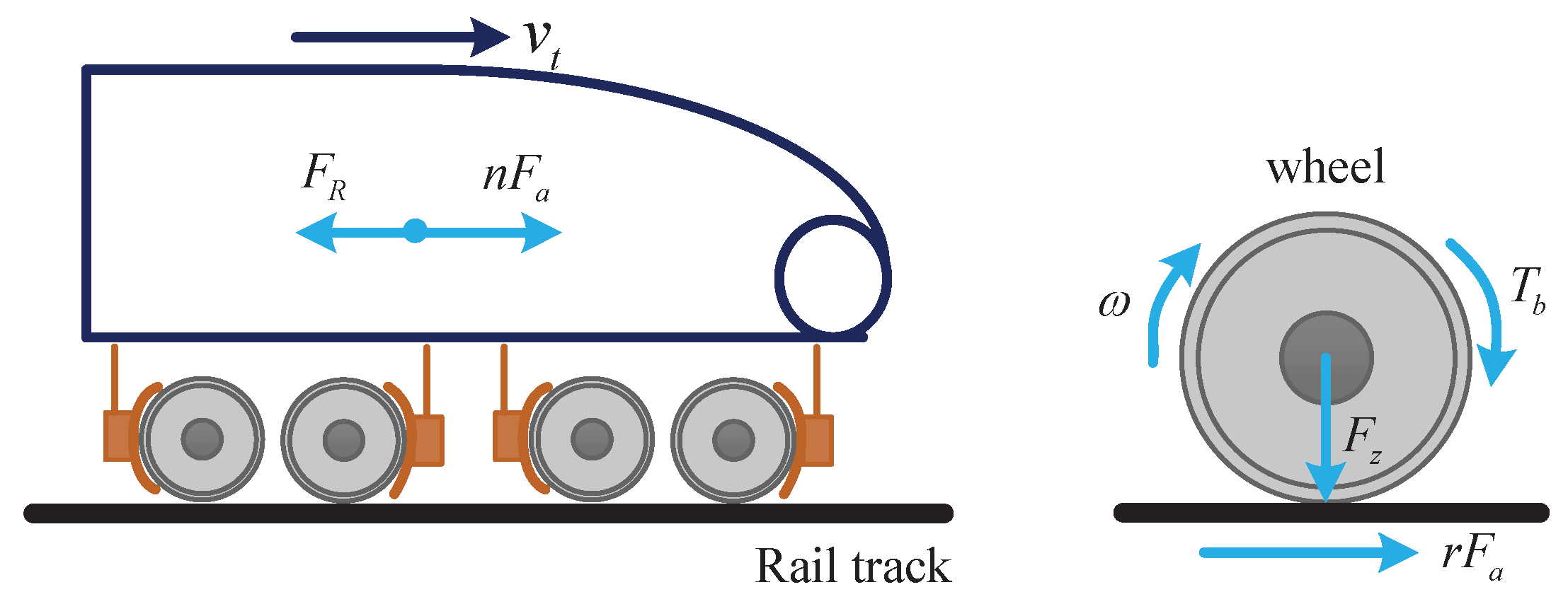
2.1. High-Speed Train Model

Figure 1 shows the longitudinal dynamics of a high-speed train and the driving wheel dynamics. From this figure, a quarter train model [3] is utilized in this paper to describe the motion of a high-speed train. According to the law of the fixed-axis rotation and Newton’s second law, the corresponding driving wheel model and train dynamics can be denoted as:
I w ω ˙ = T b r F a ,
m v ˙ t = n F a F R ,
F R = c 0 + c 1 v t + c 2 v t 2 .
Specifically, both the adhesion force F a and total effective torque T b are negative for the train braking scenarios. The adhesion force F a can be expressed by the adhesion coefficient μ :
F a = F z μ .
Researches indicate that the adhesion coefficient μ is a highly nonlinear function about the slip ratio λ [1]. The slip ratio represents the relative difference between the vehicle velocity and wheel velocity and can be defined as:
λ = v t ω r v t .
Due to the vehicle velocity v t being unknown, the slip ratio λ cannot be obtained directly according to Equation (5). Thus, based on the multi-sensor data fusion method, the slip ratio is usually inferred from acceleration and wheel speed sensors [36]. Moreover, from Figure 2, it can be found that the relationship between the adhesion coefficient and the slip ratio is complicated, which changes with the wheel-rail contact conditions and vehicle velocities. The adhesion characteristics between the wheels and rails are coupled with the external environment, which brings remarkable challenges to the design of an active braking controller for high-speed trains.

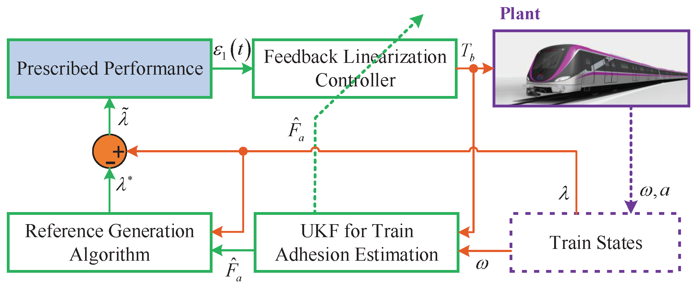
2.2. Active Braking Control Approach

From Formula (4), we can know that the adhesion force is determined by the adhesion coefficient and the wheel vertical load. During the train braking process, the wheel vertical load is constant, but the adhesion coefficient changes with the slip ratio under different wheel-rail contact conditions and vehicle velocities, which can be seen in Figure 2. It is worth noting that an optimal slip ratio always exists that can make the adhesion coefficient maximize, i.e., μ m a x = f ( λ * ) . If the real-time slip ratio is larger than the optimal slip ratio, the train will operate in an unstable area and the adhesion coefficient decreases rapidly. In order to shorten the brake distance and alleviate the wear of wheels and rails, the high-speed train should operate in a neighborhood of optimal slip ratio λ * so that the maximum wheel-rail adhesion can be maintained. To this end, an advanced active braking control with a rapid and accurate tracking performance is highly required for train braking systems, where a reliable optimal slip ratio generation should be provided.
Following the above discussion, there are three main difficulties in active brake control design: (i) The uncertainties and nonlinearities of the train dynamics, (ii) the time-varying and unknown optimal slip ratio for use as the reference, and (iii) the high requirements of tracking performance. Therefore, this paper proposes an estimation-based prescribed performance feedback linearization controller with reference adaptation for active braking control systems of high-speed trains. Particularly, the prescribed performance is incorporated into this controller to guarantee both the transient and steady-state control performance. For the proposed control architecture, an unscented Kalman filter is integrated to estimate the uncertain train adhesion. The estimated train adhesion will be fed back into the system model to update the designed controller, and further be utilized to generate the reference slip ratio. Figure 3 elaborates the block diagram of the proposed active braking controller.

3. Prescribed Performance Feedback Linearization Controller with Adhesion Estimation

This section details the development of an active braking controller based on a prescribed performance feedback linearization method with the purpose of enhancing the ride quality and braking capacity. Wheel slip dynamics are firstly established, and the controller is designed to regulate the wheel slip to its desired value, where both the transient and steady-state control performances are ensured by incorporating a prescribed performance function. Stability analysis of the proposed controller is also discussed.

3.1. Wheel Slip Dynamics

The wheel slip dynamics is required for the design of an active braking controller. Differentiating Equation (5), we can obtain:
λ ˙ = v ˙ t 1 λ ω ˙ r v t .
By substituting Formulas (1) and (2) into Formula (6), the wheel slip dynamics can be obtained as:
λ ˙ = n 1 λ m v t + r 2 I w v t F z μ T b r I w v t ,
where the influence of total wind resistance F R is neglected. Since n m r 2 I w , where n = 4 , the wheel slip dynamics (7) is further simplified as follows:
λ ˙ = r I w v t r F z μ T b .
Defining the tracking error as λ ˜ = λ λ * , we can derive the tracking error dynamics as:
λ ˜ ˙ = r I w v t r F z μ T b λ ˙ * .

3.2. Prescribed Performance

3.2.1. Prescribed Performance Function

To investigate the steady-state and transient tracking performance, a specific prescribed performance function is introduced. Based on the studies of [31,32], we select a positive decreasing smooth function as:
η t = η 0 η e k t + η ,
where η 0 > η and k > 0 are the designed parameters. The constrained control performance object is to hold the tracking error λ ˜ t within the bounds:
δ ̲ η t < λ ˜ t < δ ¯ η t , t > 0 ,
where δ ̲ and δ ¯ are the selected positive constant parameters.
Clearly, the transient and steady-state control performance for tracking error λ ˜ can be determined by the constrained condition (11). In Formulas (1) and (11), the upper bound of an overshoot is prescribed by the δ ¯ η 0 . The lower bound of the undershoot is determined by δ ̲ η 0 . In addition, the parameter k determines the lower bound on convergence rate, and η represents the permitted steady-state error [34]. Therefore, such control objects can be characterized by a priori selection of parameters δ ̲ , δ ¯ , k, η 0 , and η .

3.2.2. Error Transformation

To handle the above prescribed performance control issue, a tracking error transformation is adopted to transform the control error behavior into an equivalent unconstrained one [32]. For this purpose, we define the following error transformation function:
λ ˜ t = η t S ε 1 ,
where the variable ε 1 is the transformed tracking error, and S ε 1 is a smooth, strictly increasing function, satisfying the following properties:
(1) δ ̲ < S ε 1 < δ ¯ , ε 1 L ,
(2) lim ε 1 S ε 1 = δ ̲ , and lim ε 1 + S ε 1 = δ ¯ .
Thus, the following error transformation function is employed in this section:
S ε 1 = δ ¯ e ε 1 δ ̲ e ε 1 e ε 1 + e ε 1 .
Due to the properties of function S ε 1 and η t η > 0 , the inverse function of S ε 1 exists and we can obtain:
ε 1 = S 1 λ ˜ t η t = 1 2 ln ξ t + δ ̲ δ ¯ ξ t ,
where ξ t = λ ˜ t η t is a measurable variable.
Remark 1.
At the initial condition t = 0 , the parameters η 0 , δ ̲ , δ ¯ should be appropriately selected such that δ ̲ η 0 < λ ˜ 0 < δ ¯ η 0 satisfies, and the boundedness of ε 1 (i.e., ε 1 L , t > 0 ) is guaranteed. Then, the condition δ ̲ < S ε 1 < δ ¯ holds and the tracking error can be constrained within the prescribed region δ ̲ η t < λ ˜ t < δ ¯ η t . Therefore, the following Lemma can be provided.
Lemma 1
([32]). The tracking error dynamics (9) is invariant through the error transformation of (14). Thus, the control issue of (9) with the constrained condition (11) can be transformed into stabilizing the transformed error ε 1 .

3.3. Unscented Kalman Filter-Based Feedback Linearization Controller

In this subsection, a feedback linearization controller based on an unscented Kalman filter is developed to stabilize the transformed error (14), thus guaranteeing both the steady-state and transient tracking performance under the uncertainty and nonlinearity of the train braking system.

3.3.1. Feedback Linearization Controller

Differentiating the transformed error (14), we can obtain:
ε ˙ 1 = S 1 ξ ξ ˙ = 1 2 1 ξ + δ ̲ 1 ξ δ ¯ λ ˜ ˙ η λ ˜ η ˙ η 2 = r 2 I w v t F z μ r I w v t T b λ ˙ * λ ˜ η ˙ η ,
where = 1 2 η 1 ξ + δ ̲ 1 ξ δ ¯ .
Define f t = r 2 I w v t F z μ η ˙ η λ ˜ and g t = r I w v t for v t > 0 , the transformed error dynamics (15) is simplified:
ε ˙ 1 = Δ f t g t T b λ ˙ * .
Let us first assume that the parameters in (16) are definitely known, then a feedback linearization controller can be designed as:
T b = g t K 1 ε 1 + f t λ ˙ * ,
where K 1 > 0 is the control gain, and g t = 1 g t .
The controller (17) requires the full state signals, especially for vehicle velocity. As mentioned above, vehicle velocity v t can be obtained by using the measurements of acceleration and wheel speed [36]. Besides, the control parameter is updated by λ ˜ and η and thus can be regarded as a measurable variable.
Moreover, the resolution of the uncertain term r 2 I w v t F z μ in the ideal feedback linearization controller (17) is another challenge. Except for the uncertain adhesion coefficient, the train mass also varies with the number of passengers, which cannot be accurately measured. To address this issue, a continuous-time unscented Kalman filter is developed to estimate this uncertain term F z μ (i.e., adhesion force F a ), then the estimated uncertainty will be utilized to compensate for the controller (17).

3.3.2. Unscented Kalman Filter for Adhesion Estimation

This paper introduces a continuous-time unscented Kalman filter (CTUKF) algorithm to estimate the uncertain adhesion force F a using the measurements of braking torque and wheel speed. In [37], the CTUKF algorithm is originally designed for the system state estimation. We will utilize it to achieve the uncertain parameter estimation with some minor changes in this paper. The estimated adhesion force F a is represented by the estimated parameter φ , and on the basis of the driving wheel model (1), the continuous-time filtering model can be expressed as:
φ ˙ ( t ) = d ˙ v ( t ) ,
z ˙ ( t ) = h ( φ ( t ) , ω ( t ) , T b ( t ) , t ) + d ˙ w ( t ) ,
where z ( t ) represents the nonlinear observation on φ ( t ) , d v ( t ) , h ( φ ( t ) , ω ( t ) , T b ( t ) , t ) denotes the driving wheel dynamics, and both d v ( t ) and d w ( t ) are independent Brownian motions with diagonal diffusion matrices R v ( t ) and R w ( t ) , respectively.
Under the assumption of Δ t nearing zero sufficiently, using the approximation of numerical Euler method, we can obtain:
φ ( t + Δ t ) φ ( t ) = Δ d v ( t ) + o ( Δ t ) ,
z ( t + Δ t ) z ( t ) = h ( φ ( t ) , ω ( t ) , T b ( t ) , t ) Δ t + Δ d w ( t ) + o ( Δ t ) ,
where Δ v ( t ) N ( 0 , R v ( t ) Δ t ) , Δ w ( t ) N ( 0 , R w ( t ) Δ t ) and o ( Δ t ) is a function satisfying o ( Δ t ) / Δ t 0 when Δ t 0 .
The initial parameter φ ( t 0 ) can be set as a random value. The mean and covariance are initialized with the known φ ^ ( t 0 ) and P ¯ ( t 0 ) , where t 0 is the initial time. Based on Formula (20), the estimated mean and covariance can be given as φ ^ ( t ) and P ¯ ( t ) . Then, a collection of sigma points are generated around the estimated mean as:
( t ) = φ ^ ( t ) φ ^ ( t ) + σ P ¯ ( t ) φ ^ ( t ) σ P ¯ ( t ) ,
^ ( t + Δ t ) = ( t ) + o ( Δ t ) ,
where σ is a scaling parameter and represents the spread of sigma points.
Then, the prediction of mean and covariance can be obtained as:
φ ^ ( t + Δ t ) = φ ^ ( t + Δ t ) w m ,
P ¯ ( t + Δ t ) = φ ^ ( t + Δ t ) W ( t + Δ t ) + R v ( t ) Δ t ,
where w m = W 0 m W 2 N m , N = 3 , and weighting parameters W i ( m ) are defined as:
W 0 ( m ) = σ / ( N + σ ) , W i ( m ) = 1 / ( 2 N + 2 σ ) , i = 1 , . . . , 2 N .
W = I w m w m × d i a g W 0 c W 2 N c × I w m w m T ,
and the weighting parameters W i c are defined as:
W 0 ( c ) = σ / ( N + σ ) + ( 1 α 2 + β ) , W i ( c ) = 1 / ( 2 N + 2 σ ) , i = 1 , . . . , 2 N .
In Formula (25), the diagonal diffusion matrix R v ( t ) determine the convergence rate of parameter estimation. This matrix can be set as R v ( t ) = γ P ¯ ( t ) , where γ [ 0 , 1 ] . Then, the sigma point prediction matrix ( t + Δ t ) can be obtained. Further, the estimated function output difference can be achieved as:
z ^ ( t + Δ t ) = Z ( t + Δ t ) w m ,
where the prediction matrix Z ( t + Δ t ) = h ( ω ( t ) , ( t + Δ t ) , T b ( t ) , t ) + o ( Δ t ) .
Furthermore, according to the statistics of the transformed sigma points, the measurement covariance Π p ( t + Δ t ) and the cross-correlation covariance Π T p ( t + Δ t ) are computed as follows,
z ( t + Δ t ) = Z ( t + Δ t ) W [ Z ( t + Δ t ) ] T + R w ( t ) Δ t , T z ( t + Δ t ) = ( t + Δ t ) W [ Z ( t + Δ t ) ] T .
Then, the Kalman gain is computed as:
K ( t + Δ t ) = T z ( t + Δ t ) z 1 ( t + Δ t ) ,
and the parameter φ ^ and the error covariance matrix can be computed as:
φ ^ ( t + Δ t ) = φ ^ ( t + Δ t ) + K ( t + Δ t ) ( Δ z z ^ ( t + Δ t ) ) ,
P ¯ ( t + Δ t ) = P ¯ ( t + Δ t ) K ( t + Δ t ) z ( t + Δ t ) K T ( t + Δ t ) ,
where the term Δ z = z ( t + Δ t ) z ( t ) denotes the measured difference.
Finally, substituting Z ( t + Δ t ) , z ^ ( t + Δ t ) , z ( t + Δ t ) , T z ( t + Δ t ) , φ ^ ( t + Δ t ) , and P ¯ ( t + Δ t ) into Formulas (28)−(30), we can obtain the following differential equations to estimate the uncertain adhesion force iteratively.
K ( t ) = ( t ) W h T ( ω ( t ) , ( t ) , T b ( t ) , t ) [ R w ( t ) ] 1 ,
φ ^ ˙ t = K ( t ) [ ω ˙ ( t ) h ( ω ( t ) , ( t ) , T b ( t ) , t ) w m ] ,
P ¯ ˙ ( t ) = R v ( t ) K ( t ) R w ( t ) K T ( t ) .
The convergence of the designed unscented Kalman filter is analyzed as follows. Based on the contraction of Theorem 3.7 and the incremental stability of Corollary 3.8 in reference [38], there exists the following Lemma to guarantee the convergence of the unscented Kalman filter.
Lemma 2
([38]). If the designed unscented Kalman filter satisfies the following conditions: (i) The contraction which requires that the process noise matrix is positive definite and the covariance of the estimated state is bounded and (ii) the incremental stability which requires that the estimation model has a Lipschitz continuity and restriction on growth, the estimation error exponentially converges to a bounded region, satisfying:
lim t E x ^ t x t 2 q ,
where x ^ ( t ) denotes the estimated mean of system state, x ( t ) is the corresponding actual mean, the upper bound q relates to an evaluate of stochastic contraction, and E · is the expectation operator.
Remark 2.
For the designed unscented Kalman filter, the convergence conditions in Lemma 2 can be satisfied due to the positive definite R v ( t ) (the process noise matrix), the bounded covariance P ¯ , and the driving wheel model (1) meeting the Lipschitz continuity and restriction on growth because of the passivity of friction characteristics [39]. Therefore, the estimated mean φ ^ ( t ) (i.e., F ^ a ( t ) ) exponentially converges to the actual mean φ ( t ) (i.e., F a ( t ) ) with a bounded region.
With the above parameter estimation procedures, we can obtain the estimated adhesion force F ^ a . Then, the estimated adhesion force F ^ a is fed back into the ideal controller (17) to compensate for the defect of feedback linearization controller. Consequently, the feedback linearization controller with the prescribed performance is established as follows:
T b = g t K 1 ε 1 + f ^ t λ ˙ * ,
where the control parameter f ^ t is updated by f ^ t = r 2 I w v t F ^ a η ˙ η λ ˜ .

3.3.3. Stability Analysis

In this subsection, the stability of the overall system is detailed in the following theorem.
Theorem 1.
Consider the wheel slip tracking error dynamics (9) with the uncertainty and nonlinearity. To incorporate the desired tracking performance, (9) is transformed into the error dynamics (15) with the error transformation (14) as well as the prescribed performance constraint (11). Then, the designed control law (34) can guarantee the transformation error ε 1 is asymptotic convergence, and the tracking error λ ˜ t satisfies the prescribed performance constraint (11), remaining valid for all time.
Proof of Theorem 1.
Substituting the designed control law (34) into the error dynamics (15), one can have:
ε ˙ 1 = K 1 · ε 1 + f t f ^ t .
The estimation error term f t f ^ t can be defined as Λ t , and then the error dynamics (15) is rewritten as:
ε ˙ 1 = Δ K 1 · ε 1 + Λ t .
Further, a Lyapunov function candidate can be selected as V ε = 1 2 ε 1 2 . Taking the differentiation of V ε , we can obtain:
V ˙ ε = ε 1 · ε ˙ 1 K 1 · ε 1 2 + ε 1 · Λ K 1 · V ε + V ε · Λ .
Then, we obtain:
V ˙ ε K 1 · V ε + Λ .
Solving (38), we have:
V ε e 0 t K 1 · d τ · V ε 0 + 0 t e τ t K 1 · d τ · Λ d τ .
According to Lemma 2 and Lyapunov’s theory, V ε is uniformly ultimately bounded, which means that the transformation error ε 1 is bounded and its upper bound depends on the control gain K 1 and the designed parameter estimator performance. Then, based on the inherent properties of S ε 1 and the transformation (12), we can further obtain δ ̲ η t < λ ˜ t < δ ¯ η t , t > 0 , meaning that the tracking error λ ˜ t can obtain the prescribed control performance to guarantee the transient and steady-state response. □
Remark 3.
In the designed prescribed performance control law (34), the control parameter terms f ^ t , g t are updated by the vehicle velocity v t , estimated uncertain adhesion force F a ^ , and prescribed performance parameter ℓ. Specifically, the control parameter ℓ is related to the tracking error λ ˜ , selected positive decreasing smooth function η, and constraint parameters δ ̲ , δ ¯ . The control parameter ℓ can be guaranteed not to be equal to zero by setting the parameter η , and thus the singularity issue can be avoided. Besides, the function η and constraint parameters δ ̲ , δ ¯ can be selected offline to determine the prescribed control performance based on a preliminary parameter tuning criteria [34]. Moreover, the designed active braking controller should be rectified at the extremely small value of the vehicle velocity v t , i.e., v t 0 . Under this case, the wheel slip dynamics (8) will lose its controllability. For the specific condition, the braking controller will exert a constant braking torque according to the reference deceleration.

4. Reference Slip Ratio Generation Algorithm

Besides the controller design, a reliable reference slip ratio generation algorithm should be developed. According to the analysis of Figure 2, when the slope of the adhesion curve equals to zero (i.e., μ λ = 0 ), the maximum adhesion coefficient can be obtained. For the extremum seeking, the real-time adhesion coefficient should be known. Fortunately, a continue-time unscented Kalman filter is developed for train adhesion estimation in Section 3.3.2. Benefiting from the estimated train adhesion, an on-line optimal slip ratio generation algorithm is proposed for the adaptation of the reference slip ratio.
It is worth noting that the characteristics of adhesion curves remain invariant when adhesion coefficient μ is replaced by the adhesion force F a . Defining the adhesion slope χ = F a λ , the reference slip ratio seeking approach can be designed as (42) based on the characteristics of adhesion curves.
λ * t + Δ t = λ * t 1 · sgn χ ,
where 1 denotes the step size of searching, sgn · represents the sign function, and λ * t 0 is initialized as 0.1 based on experience.
For the proposed seeking approach, the precise slope χ information is crucial, which is usually calculated by the F a / t and λ / t . Due to the sensor measurement noises, the estimation fluctuations of train adhesion and slip ratio are inevitable. It means that the ideal reference slip ratio is difficult to obtain by just using sampling data of one control cycle. Moreover, the normal form of recursive least squares is only suitable for the time-invariant parameter estimation. In this paper, the slope χ is identified by a recursive least squares with a forgetting factor to cope with the measurement noises and the varying adhesion slope. The designed forgetting factor recursive least squares algorithm for the slope identification can be expressed as:
χ ^ t + Δ t = χ ^ t + β t · F ^ a / t λ / t · χ ^ t , β t = P t · λ / t ρ + P t · λ / t 2 , P t + Δ t = 1 ρ 1 β t · λ / t P t ,
where χ ^ denotes the predicted adhesion slope, ρ represents the forgetting factor, χ ^ 0 is set as 0, and P 0 is initialized as a sufficiently large positive real number.
In this designed algorithm, the forgetting factor ρ determines the influence of historical sampling data on parameter identification, and the parameter gain P can be reset as the initial value to handle the parameter variation issue. To be specific, when detecting adhesion changes, the designed algorithm will reset the parameter gain P and regulate the forgetting factor ρ to achieve forgetting the past wheel-rail contact features while capturing the new ones. Further, the forgetting factor ρ is designed to fit the adhesion changes as follows:
ρ t = ρ 1 i f F a / t ζ , ρ t = ρ 2 i f F a / t > ζ ,
where ζ is a positive real number, which is selected based on the statistic characteristics of F a / t .

5. Experimental Validation

In this section, the proposed active braking control approach is verified by the hardware in loop simulation (HILS) train braking test platform. Firstly, the performance of the unscented Kalman filter for train adhesion estimation is verified. Then, the performance of proposed optimal slip ratio generation algorithm is provided and analyzed under different wheel-rail contact conditions. Finally, detailed control performance comparisons are conducted to verify the effectiveness and superiority of the proposed method.

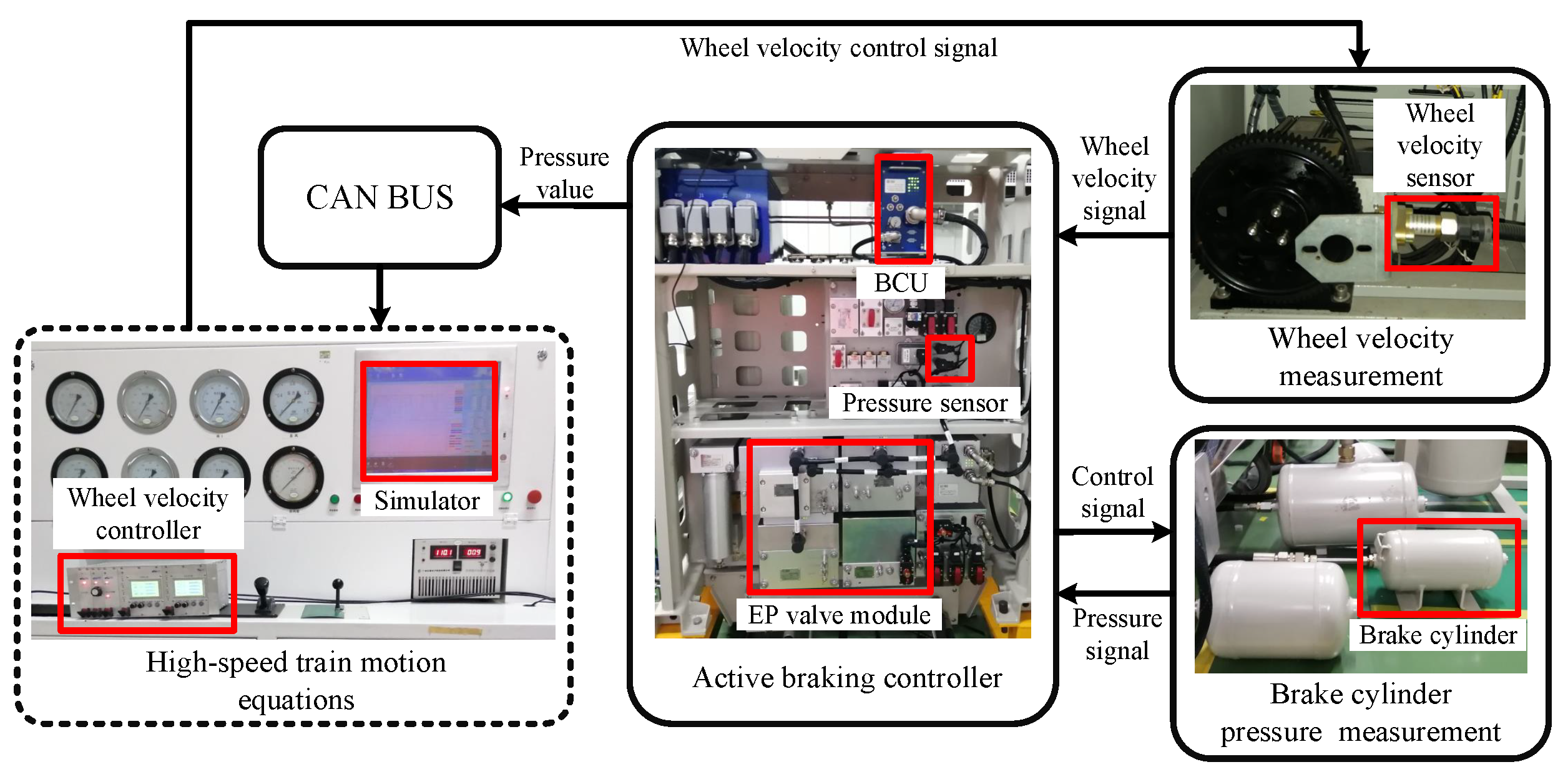
5.1. Experimental Setup

As shown in Figure 4, a HILS train braking test platform is established to simulate a real system. The braking system consists of the brake cylinder, pressure sensor, electro-pneumatic (EP) valve module, and brake control unit (BCU), which operate as the actual equipment. The braking torque T b is provided by the brake cylinder pressure P c and the corresponding relationship is represented by: T b = ϑ · P c , where the parameter ϑ can be obtained as ϑ = 33.56 by experimental tests. The designed active braking control approach is implemented in the BCU.
Based on the high-speed train motion equations, the train states, including the train velocity v t , the wheel angular speed ω are updated in a real-time simulator. The BCU can obtain the actual gear rotational velocity from the wheel velocity sensor. The actual gear rotational velocity corresponds to the updated wheel angular speed ω . Moreover, a Burckhardt and Reimpell friction model [26] is utilized by the simulator to emulate the train adhesion μ , and its function is μ = 1 α 0 1 e α 1 λ α 2 λ for the train braking process, where constant parameters α 0 , α 1 , α 2 vary with different rail conditions. Therefore, the changes of wheel-rail contact condition can be simulated through altering these friction parameters. The electrical interface between the real braking system and the virtual train dynamics is established to simulate that of an actual high-speed train.
The high-speed train parameters and the proposed control system parameters are listed in Table 2 and Table 3, respectively. The UKF is an abbreviation of the unscented Kalman filter; the RSRGA is an abbreviation of the reference slip ratio generation algorithm; and the E-PPFC is an abbreviation of the proposed estimation-based prescribed performance feedback linearization control. The initial train velocity v t t 0 is set to 50 m/s, and the initial wheel speed is equal to the initial train velocity. The sampling time is set to 1 ms. Furthermore, to better analyze the control performance of the proposed control approach, different wheel-rail contact conditions are considered as follows: (i) for t = [ 0 , 2 ) s, the dry contact condition is set ( α 0 = 0.3546 , α 1 = 23.129 , α 2 = 0.1246); (ii) for t = [ 2 , 4 ) s, the snowy contact condition is set ( α 0 = 0.1646 , α 1 = 26.731 , α 2 = 0.1646); and (iii) for t = [ 4 , 6 ] s, the wet contact condition is set ( α 0 = 0.2546 , α 1 = 24.617 , α 2 = 0.1360). The varied wheel-rail contact conditions will cause the adhesion coefficient μ changes in the slip dynamics (9), and the reference optimal slip ratio λ * changes.

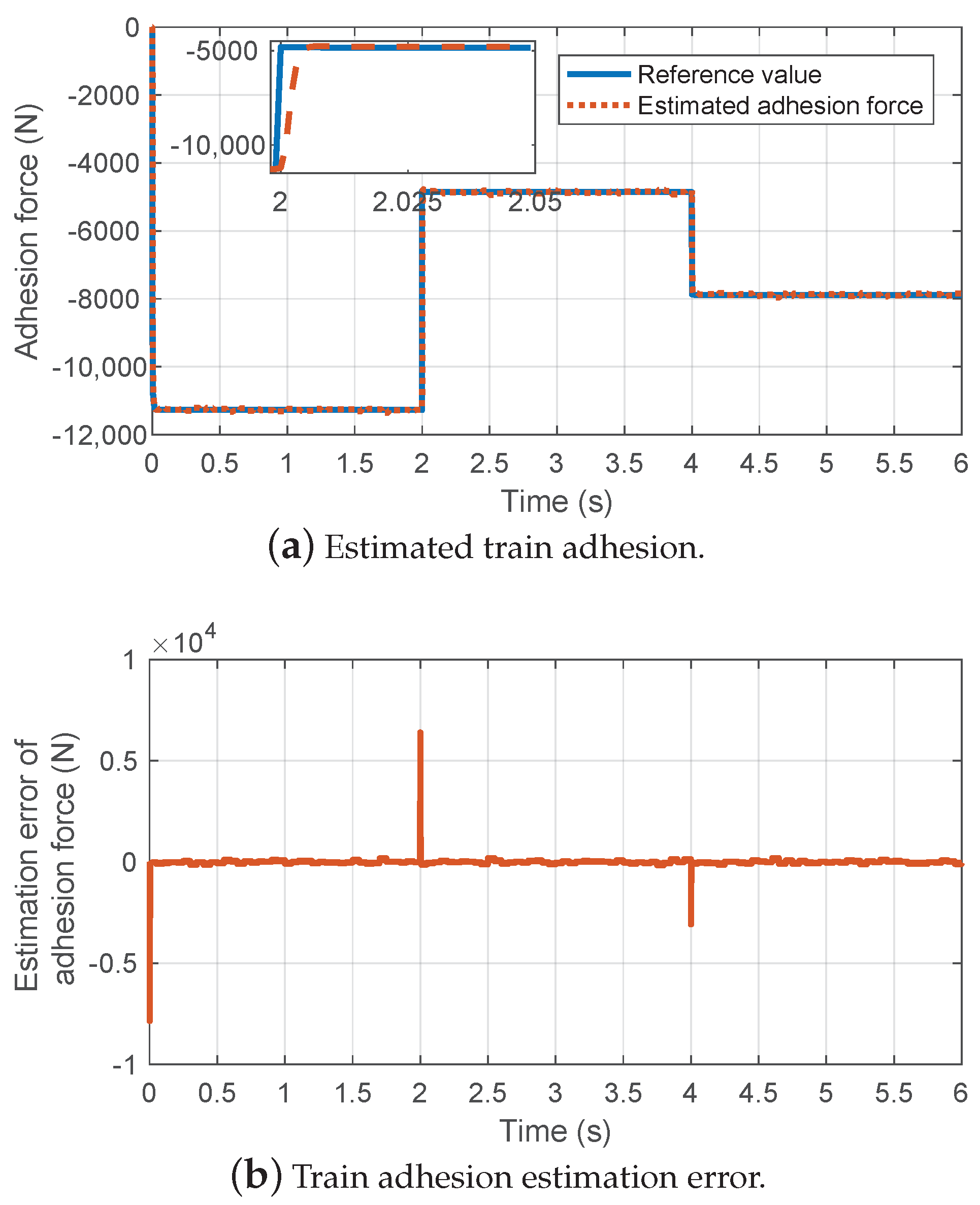
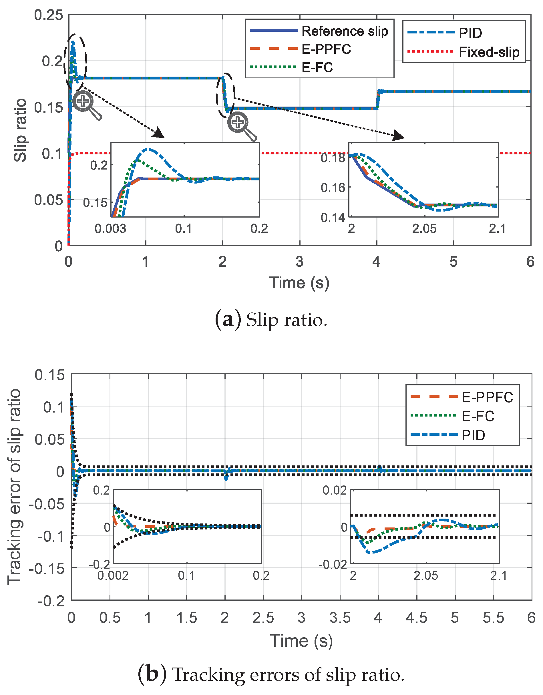
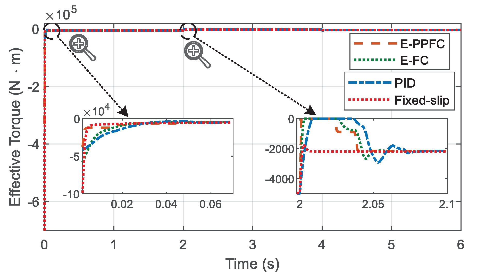
5.2. Experimental Results

This subsection presents the experimental results to validate the proposed active braking control approach under the varying wheel-rail contact conditions. Firstly, we provide and analyze the experimental results of the train adhesion estimation and the reference slip ratio generation. Then, comparative braking experiments are conducted to indicate the effectiveness and superiority of the proposed active braking control approach.
Figure 5 presents the train adhesion estimation results based on an unscented Kalman filter. As shown in Figure 5, the designed train adhesion estimator provides a rapid and accurate adhesion estimation under the different wheel-rail contact conditions. Moreover, whether the wheel-rail contact conditions are in positive or negative jump, the estimated adhesion can rapidly converge to the actual value. The accurate estimated adhesion will be used to compensate for the uncertainty in the designed prescribed performance feedback linearization control law, and it will provide the critical information for obtaining the reference optimal slip ratio.
The experimental results of the optimal slip ratio estimation are illustrated in Figure 6. As shown, when the wheel-rail contact condition is changed, the corresponding optimal slip ratio can be obtained in a short period. For example, when the first wheel-rail contact condition jump occurs at t = 2 s, the estimated optimal slip ratio converges to the reference value within 50 ms. Then, the estimated slip ratio will be input into the active braking controller as the control target.
Furthermore, in order to verify the superiority of the proposed active braking controller (represented by E-PPFC), it is conducted by comparing with estimation-based feedback linearization control (represented by E-FC), PID control, and fixed reference slip ratio-based control (represented by Fixed-slip). Specifically, the fixed reference slip ratio is set as 0.1 according to the engineering experience, and the parameters of PID control are set as K p = 100 , K i = 10 , K d = 1 . Figure 7, Figure 8 and Figure 9 provide the corresponding braking experimental results.
Figure 7 presents train states including the vehicle velocity, wheel velocity, and train adhesion coefficient under the four different control approaches. As shown in Figure 7, although the Fixed-slip control method can prevent the wheel from locking, the obtained adhesion coefficient is not optimal compared with the other control methods. It indicates that the Fixed-slip control method has the maximum braking distance among the four control approaches. For the other control methods that use the optimal slip ratio as the reference, all of them can make the train in the maximum adhesion state quickly and ensure the maximum braking capacity.
Figure 8 describes the slip ratio control performance of different control approaches under the varying wheel-rail contact conditions. As can be seen from the figure, the PID control method has the slowest convergence rate, the maximum overshoot, and adjustment time. The PID parameters can be regulated to obtain an ideal control performance, but the parameter determination process is typically time-consuming. Compared with the PID control method, the estimation-based feedback linearization control method that only needs to adjust one control parameter, obtain a better control performance. As for the proposed estimation-based prescribed performance feedback linearization control method, it obtains the best transient performance and steady-state performance among these methods. As shown in Figure 8b, the tracking error of the proposed control method satisfies the prescribed performance constraints during the whole period. The experimental results show that the proposed method can achieve the best slip ratio tracking performance under the varying wheel-rail contact conditions when compared with the other two methods.
Figure 9 shows the braking torque under different control approaches. From this figure, compared with the other methods, it can be found that the proposed feedback linearization control with the prescribed performance method has the fastest response speed when the slip ratio changes at 0 s and 2 s. Specifically, the rail condition becomes worse at 2 s, then the braking torque should reduce to make the wheel slip track the decreased reference value. As can be seen from the enlarged figure, the proposed control method makes the braking torque decrease rapidly and converge to the steady-state value. Compared with the PID control method and the estimation-based feedback linearization control method, the proposed control method does not have the overshoot, and has the minimum convergence time.
Table 4 summarizes the braking performance comparisons of different control methods, where the braking distances are adopted to evaluate the braking capacity and the acceleration variances are utilized to evaluate the driving comfort. The train braking distances are obtained by integrating vehicle velocity, and the acceleration variances are calculated by using the data of three stages, including the first braking action, as well as the first and second wheel-rail contact condition changes. In the three stages, the train acceleration will vary significantly. As can be seen from Table 4, the Fixed-slip control method results in the longest braking distance because it does not make full use of the train adhesion. Moreover, the proposed prescribed performance active braking control method obtains the shortest braking distance and the minimum acceleration variance, which means that the proposed method has the best braking performance and driving comfort. The above experimental results further demonstrate the effectiveness and superiority of the proposed method.

6. Conclusions

In this paper, a novel prescribed performance active braking control is proposed, which can ensure a high-speed train operates at its maximum adhesion state under the different wheel-rail contact conditions. The developed active braking controller consists of four parts: Prescribed performance function, feedback linearization, unscented Kalman filter, and reference generation algorithm. The prescribed performance function is integrated to guarantee both steady-state and transient control performances. The estimation-based feedback linearization control is designed to handle the uncertainty of wheel-rail adhesion and system nonlinearity, wherein the wheel-rail adhesion is estimated by an unscented Kalman filter and fed back into the control law to achieve active compensation. Finally, an optimal slip ratio generation algorithm is designed to provide a reliable reference. The proposed controller is demonstrated to stabilize the wheel slip at its desired value with the specific tracking performance, thus significantly improving the braking capacity. Comparative experiment results verify the superiority and effectiveness of the developed controller.

Author Contributions

Conceptualization, R.Z. and J.P.; methodology, R.Z. and B.C.; software, R.Z.; validation, B.C., K.G. and Z.H.; formal analysis, B.C.; investigation, R.Z.; resources, Z.H.; data curation, K.G.; writing—original draft preparation, R.Z. and B.C.; writing—review and editing, R.Z. and J.P.; visualization, R.Z. and B.C.; supervision, Z.H.; project administration, J.P.; funding acquisition, Y.Y. All authors have read and agreed to the published version of the manuscript.

Funding

This research were funded by the National Natural Science Foundation of China (Grant No. 61873353, 62172448), and General Project of Hunan Natural Science Foundation (Grant No. 2021JJ30876, 2021JJ30868).

Institutional Review Board Statement

Not applicable.

Informed Consent Statement

Not applicable.

Data Availability Statement

Not applicable.

Conflicts of Interest

The authors declare no conflict of interest.

References

  1. Picasso, B.; Caporale, D.; Colaneri, P. Braking control in railway vehicles: A distributed preview approach. IEEE Trans. Autom. Control 2018, 63, 189–195. [Google Scholar] [CrossRef]
  2. Chen, B.; Huang, Z.; Zhang, R.; Jiang, F.; Liu, W.; Li, H.; Wang, J.; Peng, J. Adaptive slip ratio estimation for active braking control of high-speed trains. ISA Trans. 2021, 112, 302–314. [Google Scholar] [CrossRef]
  3. Cai, W.; Li, D.; Song, Y. A novel approach for active adhesion control of high-speed trains under antiskid constraints. IEEE Trans. Intell. Transp. Syst. 2015, 16, 3213–3222. [Google Scholar] [CrossRef]
  4. Lee, N.J.; Kang, C.G. Wheel slide protection control using a command map and Smith predictor for the pneumatic brake system of a railway vehicle. Veh. Syst. Dyn. 2016, 54, 1491–1510. [Google Scholar] [CrossRef]
  5. Chen, E.P.; Cheng, J.; Tu, J.H.; Lin, C.L. Sensorless Driving/Braking Control for Electric Vehicles. Actuators 2020, 9, 22. [Google Scholar] [CrossRef] [Green Version]
  6. Tavernini, D.; Vacca, F.; Metzler, M.; Savitski, D.; Ivanov, V.; Gruber, P.; Karci, A.E.H.; Dhaens, M.; Sorniotti, A. An explicit nonlinear model predictive ABS controller for electro-hydraulic braking systems. IEEE Trans. Ind. Electron. 2020, 67, 3990–4001. [Google Scholar] [CrossRef]
  7. Savaresi, S.M.; Tanelli, M. Active Braking Control Systems Design for Vehicles; Springer Science & Business Media: Berlin/Heidelberg, Germany, 2010. [Google Scholar]
  8. Diao, L.; Zhao, L.; Jin, Z.; Wang, L.; Sharkh, S.M. Taking traction control to task: High-adhesion-point tracking based on a disturbance observer in railway vehicles. IEEE Ind. Electron. Mag. 2017, 11, 51–62. [Google Scholar] [CrossRef]
  9. Aksjonov, A.; Augsburg, K.; Vodovozov, V. Design and simulation of the robust ABS and ESP fuzzy logic controller on the complex braking maneuvers. Appl. Sci. 2016, 6, 382. [Google Scholar] [CrossRef]
  10. Pichlik, P.; Zdenek, J. Locomotive Wheel Slip Control Method Based on an Unscented Kalman Filter. IEEE Trans. Veh. Technol. 2018, 67, 5730–5739. [Google Scholar] [CrossRef]
  11. Formentin, S.; Novara, C.; Savaresi, S.M.; Milanese, M. Active Braking Control System Design: The D2-IBC Approach. IEEE/ASME Trans. Mechatronics 2015, 20, 1573–1584. [Google Scholar] [CrossRef]
  12. Radac, M.B.; Precup, R.E. Data-driven model-free slip control of anti-lock braking systems using reinforcement Q-learning. Neurocomputing 2018, 275, 317–329. [Google Scholar] [CrossRef]
  13. Sun, J.; Xue, X.; Cheng, K.W.E. Fuzzy Sliding Mode Wheel Slip Ratio Control for Smart Vehicle Anti-Lock Braking System. Energies 2019, 12, 2501. [Google Scholar] [CrossRef] [Green Version]
  14. Chen, Y.; Dong, H.; Lü, J.; Sun, X.; Guo, L. A super-twisting-like algorithm and its application to train operation control with optimal utilization of adhesion force. IEEE Trans. Intell. Transp. Syst. 2016, 17, 3035–3044. [Google Scholar] [CrossRef]
  15. de Jesús Rubio, J. Robust feedback linearization for nonlinear processes control. ISA Trans. 2018, 74, 155–164. [Google Scholar] [CrossRef]
  16. Yang, S.; Wang, P.; Tang, Y. Feedback Linearization-Based Current Control Strategy for Modular Multilevel Converters. IEEE Trans. Power Electron. 2018, 33, 161–174. [Google Scholar] [CrossRef]
  17. Lascu, C.; Jafarzadeh, S.; Fadali, M.S.; Blaabjerg, F. Direct Torque Control With Feedback Linearization for Induction Motor Drives. IEEE Trans. Power Electron. 2017, 32, 2072–2080. [Google Scholar] [CrossRef]
  18. Poursamad, A. Adaptive feedback linearization control of antilock braking systems using neural networks. Mechatronics 2009, 19, 767–773. [Google Scholar] [CrossRef]
  19. Wu, Y.; Isidori, A.; Lu, R.; Khalil, H.K. Performance Recovery of Dynamic Feedback-Linearization Methods for Multivariable Nonlinear Systems. IEEE Trans. Autom. Control 2020, 65, 1365–1380. [Google Scholar] [CrossRef]
  20. Sariyildiz, E.; Oboe, R.; Ohnishi, K. Disturbance Observer-based Robust Control and Its Applications: 35th Anniversary Overview. IEEE Trans. Ind. Electron. 2020, 67, 2042–2053. [Google Scholar] [CrossRef] [Green Version]
  21. Chaudhari, S.; Shendge, P.; Phadke, S.B. Dynamic Nonlinear Gradient Observer based Extremum Seeking Control for Optimum Braking. IEEE Trans. Ind. Electron. 2021. [Google Scholar] [CrossRef]
  22. Zhang, Z.; Yang, Z.; Zhou, G.; Liu, S.; Zhou, D.; Chen, S.; Zhang, X. Adaptive Fuzzy Active-Disturbance Rejection Control-Based Reconfiguration Controller Design for Aircraft Anti-Skid Braking System. Actuators 2021, 10, 201. [Google Scholar] [CrossRef]
  23. Patil, A.; Ginoya, D.; Shendge, P.; Phadke, S. Uncertainty-estimation-based approach to antilock braking systems. IEEE Trans. Veh. Technol. 2015, 65, 1171–1185. [Google Scholar] [CrossRef]
  24. Vafamand, N.; Arefi, M.M.; Khayatian, A. Nonlinear system identification based on Takagi-Sugeno fuzzy modeling and unscented Kalman filter. ISA Trans. 2018, 74, 134–143. [Google Scholar] [CrossRef] [PubMed]
  25. Xu, X.; Tian, X.; Zhou, L.; Li, Y. A decision-tree based multiple-model UKF for attitude estimation using low-cost MEMS MARG sensor arrays. Measurement 2019, 135, 355–367. [Google Scholar] [CrossRef]
  26. Uyulan, C.; Gokasan, M.; Bogosyan, S. Comparison of the re-adhesion control strategies in high-speed train. Proc. Inst. Mech. Eng. Part I J. Syst. Control Eng. 2018, 232, 92–105. [Google Scholar] [CrossRef] [Green Version]
  27. Liu, G.; Xu, C.; Li, H.; Jiang, K.; Wang, K. State of charge and online model parameters co-estimation for liquid metal batteries. Appl. Energy 2019, 250, 677–684. [Google Scholar] [CrossRef]
  28. Li, D.; Yu, Y.; Jin, Q.; Gao, Z. Maximum power efficiency operation and generalized predictive control of PEM (proton exchange membrane) fuel cell. Energy 2014, 68, 210–217. [Google Scholar] [CrossRef]
  29. Bruce, A.L.; Goel, A.; Bernstein, D.S. Convergence and consistency of recursive least squares with variable-rate forgetting. Automatica 2020, 19, 109052. [Google Scholar] [CrossRef]
  30. Sadr, S.; Khaburi, D.A.; Rodríguez, J. Predictive slip control for electrical trains. IEEE Trans. Ind. Electron. 2016, 63, 3446–3457. [Google Scholar] [CrossRef]
  31. Bechlioulis, C.P.; Rovithakis, G.A. Adaptive control with guaranteed transient and steady state tracking error bounds for strict feedback systems. Automatica 2009, 45, 532–538. [Google Scholar] [CrossRef]
  32. Bechlioulis, C.P.; Rovithakis, G.A. Robust Adaptive Control of Feedback Linearizable MIMO Nonlinear Systems With Prescribed Performance. IEEE Trans. Autom. Control 2008, 53, 2090–2099. [Google Scholar] [CrossRef]
  33. Jing, C.; Xu, H.; Niu, X. Adaptive sliding mode disturbance rejection control with prescribed performance for robotic manipulators. ISA Trans. 2019, 91, 41–51. [Google Scholar] [CrossRef] [PubMed]
  34. Na, J.; Huang, Y.; Wu, X.; Gao, G.; Herrmann, G.; Jiang, J.Z. Active Adaptive Estimation and Control for Vehicle Suspensions With Prescribed Performance. IEEE Trans. Control Syst. Technol. 2018, 26, 2063–2077. [Google Scholar] [CrossRef] [Green Version]
  35. Hu, Q.; Shao, X.; Guo, L. Adaptive Fault-Tolerant Attitude Tracking Control of Spacecraft With Prescribed Performance. IEEE/ASME Trans. Mechatronics 2018, 23, 331–341. [Google Scholar] [CrossRef]
  36. Ivanov, V.; Savitski, D.; Shyrokau, B. A survey of traction control and antilock braking systems of full electric vehicles with individually controlled electric motors. IEEE Trans. Veh. Technol. 2014, 64, 3878–3896. [Google Scholar] [CrossRef]
  37. Sarkka, S. On unscented Kalman filtering for state estimation of continuous-time nonlinear systems. IEEE Trans. Autom. Control 2007, 52, 1631–1641. [Google Scholar] [CrossRef] [Green Version]
  38. Maree, J.P.; Imsland, L.; Jouffroy, J. On convergence of the unscented Kalman–Bucy filter using contraction theory. Int. J. Syst. Sci. 2016, 47, 1816–1827. [Google Scholar] [CrossRef]
  39. Barahanov, N.; Ortega, R. Necessary and sufficient conditions for passivity of the LuGre friction model. IEEE Trans. Autom. Control 2000, 45, 830–832. [Google Scholar] [CrossRef]
Figure 1. The longitudinal dynamics of a high-speed train and the driving wheel dynamics.
Actuators 10 00313 g001
Figure 2. Adhesion coefficient versus slip ratio curves under different wheel-rail contact conditions and vehicle velocities.
Actuators 10 00313 g002
Figure 3. Proposed prescribed performance active braking controller based on feedback linearization with adhesion estimation.
Actuators 10 00313 g003
Figure 4. Experimental platform for the pneumatic braking system of the high-speed train.
Actuators 10 00313 g004
Figure 5. Experimental results of train adhesion estimation based on unscented Kalman filter under the varying wheel-rail contact conditions.
Actuators 10 00313 g005
Figure 6. Optimal slip ratio estimation results based on forgetting factor recursive least squares algorithm under the varying wheel-rail contact conditions.
Actuators 10 00313 g006
Figure 7. Train states under different control approaches.
Actuators 10 00313 g007
Figure 8. Experimental results of slip ratio tracking under different control approaches.
Actuators 10 00313 g008
Figure 9. Experimental results of braking torque under different control approaches.
Actuators 10 00313 g009
Table 1. Nomenclature.
SymbolDefinition
λ The slip ratio
λ * The desired slip ratio
μ The adhesion coefficient
μ m a x The maximum adhesion coefficient
F a The adhesion force
F ^ a The estimated adhesion force
ω The wheel angular velocity
v t The vehicle velocity
v s The velocity difference
T b The total effective torque acting on the wheel
I w The wheel moment of inertia
mThe total mass of the high-speed train
nThe numbers of wheels
F z The wheel vertical load
F R The total wind resistance
c 0 , c 1 , c 2 Davis resistance coefficients
rThe wheel rolling radius
Table 2. The main high-speed train parameters.
ParametersValuesParametersValues
m13,800 kg I w 60.35 kg·m 2
r0.43 mn4
v t t 0 50 m/s--
Table 3. The control system parameters.
MethodsParametersValuesParametersValues
UKF P ¯ t 0 0.5 γ 0.23
σ 2 R w t 0 1
β 2--
RSRGA 1 0.01 ρ 2 0.7
ζ 1 P t 0 1
ρ 1 0.98 --
E-PPFC η 0 0.1 δ ̲ 1.2
η 0.005 δ ¯ 1.2
k30 K 1 100
Table 4. Braking performance comparisons of fixed reference slip ratio-based control, PID controller, estimation-based feedback linearization control, and the proposed control method.
MethodsBraking Distances (m)Acceleration Variances (m/s 2 )
Fixed-slip256.8391
PID254.43130.0679
E-FC254.19550.0637
E-PPFC254.04790.0564
Publisher’s Note: MDPI stays neutral with regard to jurisdictional claims in published maps and institutional affiliations.

