Article

Multifunctional Cantilevers as Working Elements in Solid-State Cooling Devices

1
Jožef Stefan Institute, Jamova cesta 39, 1000 Ljubljana, Slovenia
2
Jožef Stefan International Postgraduate School, Jamova cesta 39, 1000 Ljubljana, Slovenia
3
Department of Materials and Earth Sciences, Technical University of Darmstadt, 64287 Darmstadt, Germany
*
Authors to whom correspondence should be addressed.
Actuators 2021, 10(3), 58; https://doi.org/10.3390/act10030058
Submission received: 11 February 2021 / Revised: 9 March 2021 / Accepted: 10 March 2021 / Published: 12 March 2021
(This article belongs to the Section Precision Actuators)

Abstract

:
Despite the challenges of practical implementation, electrocaloric (EC) cooling remains a promising technology because of its good scalability and high efficiency. Here, we investigate the feasibility of an EC cooling device that couples the EC and electromechanical (EM) responses of a highly functionally, efficient, lead magnesium niobate ceramic material. We fabricated multifunctional cantilevers from this material and characterized their electrical, EM and EC properties. Two active cantilevers were stacked in a cascade structure, forming a proof-of-concept device, which was then analyzed in detail. The cooling effect was lower than the EC effect of the material itself, mainly due to the poor solid-to-solid heat transfer. However, we show that the use of ethylene glycol in the thermal contact area can significantly reduce the contact resistance, thereby improving the heat transfer. Although this solution is most likely impractical from the design point of view, the results clearly show that in this and similar cooling devices, a non-destructive, surface-modification method, with the same effectiveness as that of ethylene glycol, will have to be developed to reduce the thermal contact resistance. We hope this study will motivate the further development of multifunctional cooling devices.

1. Introduction

The electrocaloric (EC) effect is the electric-field-induced temperature change in polar materials. Its origin lies in the ordering of the dipolar system with an applied electric field, followed by disordering when the field is removed. The effect shows some potential for integration into refrigeration and cooling devices due to the relatively easy scaling of EC materials, making it possible to develop miniature refrigerators, e.g., cooling in electronics, and due to the estimated high efficiency [1,2].
With their study of the giant EC effect in PZT thin films Mischenko et al. [3] motivated a new wave of research on the topic of electrocalorics. A huge number of materials have been investigated so far, from thin films to thick films and bulk ceramics [4]. While the absolute temperature change is the largest in thin films (up to 45 K [5]), due to their small thermal mass, they are not often considered for use in actual applications. Thick films and bulk specimens are more plausible candidates for cooling on the mesoscale, such as the cooling of electronics. The largest EC effect of 5.5 K was measured in Pb(Sc0.5Ta0.5)O3 (PST) thick-film multilayers [6]. PST exhibits a high EC response for two main reasons: (i) the thick-film form allows a relatively high electric field to be applied to the material without causing a break-down [7]; and (ii) the relaxor ferroelectric nature of PST enables a high EC effect due to the absence of the ferroelectric long-range order, resulting in large entropy changes with the applied electric field. A material system with a similarly high EC response and relaxor nature is lead magnesium niobate—lead titanate, ((1 − x)Pb(Mg1/3Nb2/3)O3xPbTiO3 (PMN-xPT)). By varying the composition, x, the properties can be engineered from that typical of ferroelectrics (x > 0.35) to that more characteristic of canonical relaxors (x < 0.10) at room temperature [8]. In contrast to relaxor materials in the ergodic state, due to the long-range order of the spontaneous polarization, ferroelectric materials typically have a wider hysteresis loop [9,10]. The area of the hysteresis is related to the electrical losses in the materials [11,12,13,14], where the losses are manifested as an increase in the temperature during field cycling and are thus detrimental to the EC cooling [15]. The extent of heating due to losses can be dramatic, for example, when PZT multilayers were cycled with a field frequency of 100 Hz their temperature increased by 100 °C [13]. For the successful implementation of EC cooling, such losses must be minimized [16].
Several attempts have been made to implement EC cooling in actual applications [17]. The different approaches can be divided into three groups that differ in terms of the way the heat management is assessed. The first group of fluid-based devices use a heat-transfer fluid to transfer the heat between the heat sink and the heat source. The device consists of EC elements that are sunk into silicone oil to provide active EC regeneration (AER). This AER is achieved with the oscillatory pumping of silicone oil across the EC elements according to the EC cycle and leads to temperature changes that are several times larger than the EC temperature change of an individual EC element [18,19,20]. The second group of cooling devices is based purely, or to a large extent, on solid-state cooling. The surface works as an AER where temperature spans can be achieved that are several times larger than the EC temperature change of the individual elements [21,22,23,24,25]. Solid-state cooling has the potential for use in microelectronics and small-scale devices due to its good scalability. However, here the heat transfer is from solid to solid, which is problematic due to the large thermal resistivity of the thermal contacts. In addition, the described devices need an external mechanical component that manages the heat and creates a temperature gradient in the device. A step further in solid-state cooling has been made by the third group of devices, which use the coupling of the EC and intrinsic actuation of the material for solid-state cooling without any external components [26]. One such device was recently proposed by Ma et al. [27,28], where polymer-based thick films were used. Here, the device exploits the EC effect and the electrostatic effect of a multifunctional material at the same time. In this case, upon the application of an electric field, the polymer element bends, making a contact with a heat sink, where the heat is removed. Upon switching off the electric field the element returns to its initial position and absorbs the heat from the heat source.
Our previous theoretical studies using finite-element modelling [26] confirmed that a cascade of cantilever elements using a PMN-xPT ceramic material could be efficient for cooling purposes based on the concept of the third-group cooling devices. Here, we upgrade those studies by constructing and evaluating the operation of a simplified cooling device. The device consists of a cascade of cantilevers made from PMN, which upon application of the electric field bend, due to electromechanical (EM) effect, and change temperature, due to the EC effect. In this way, unlike in the study by Ma et al. [22], no additional electrostatic effects are needed to induce the bending of the cantilever, simplifying the construction and operability of the device. When an electric field is applied sequentially to the cascade of such cantilevers, it results in a temperature gradient larger than the EC effect of the individual elements. By first developing and optimizing the fabrication procedure for the cantilevers, consisting of a combination of tape casting and screen-printing technologies, we analyse in the present study the electrical, EM and EC properties of the cantilevers. We observed a reduction in the response of the cantilevers compared to the same PMN composition in bulk ceramics, most probably due to the mechanical stresses present in the former. Nonetheless, the cantilevers exhibited large tip deflections, showing suitability as working elements in the proposed EC concept. The proof-of-concept device was able to transfer heat from the heat source to the heat sink. We also confirmed the theoretically predicted increase in the cooling performance by increasing the number of cantilevers in the cascade, validating the design of this kind of cooling device using coupled EM and EC effects. Due to the small contact area and the relatively poor surface roughness, however, no heat regeneration occurred within the structure. Using ethylene glycol to improve the heat transfer between the elements clearly showed that the key step in the future development of such devices will be to find and design efficient ways to reduce the thermal contact resistance between the working elements.

2. Materials and Methods

2.1. Fabrication and Characterization of Bulk Ceramic Disc Samples

The ceramic samples were prepared by mechanochemical synthesis, as described elsewhere [15,16]. The samples were sintered at 1200 °C for 16 h. The samples were disc shaped with a diameter of 6 mm, a thickness of 150 μm and an Au electrode diameter of 5 mm. The electrode was deposited by magnetron sputtering (5 Pascal, Milano, Italy). For the EC measurements, the Cu wires and thermistor (GR500KM4261J15, Measurement Specialties, Hampton, VA, USA) were glued to the samples. The EC effect was evaluated in a DSC furnace (Phoenix 204 F1, Netzsch, Selb, Germany), which served as an isolated chamber or calorimeter. The samples were suspended in the chamber to avoid thermal coupling with the environment. The electric field was applied using a model 237 source measurement unit (Keithley, Cleveland, OH, USA). The raw measured temperature values were also corrected by a factor, which then reveals the EC response of the material itself. The correction factor corrects the raw measured temperature by taking into account the sample’s internal equilibration of heat; the EC heat is transferred to the wires, non-electroded area and sensor, and thus uncovers the material’s true response. The equation for the correction factor is given in [1]. The thermal properties needed for the calculation of the correction factors were found in the literature; for PMN in [29], gold wires in [30], and thermistor in datasheet (GR500KM4261J15, Measurement Specialties). The correction factor for ceramics was 1.7, while for cantilevers it was 3.2. The transverse EM response was measured using LVDT sensors and a PD05034 amplifier (TREK, Lockport, NY, USA) on samples with a diameter of 14 mm and thickness of 1 mm.

2.2. Fabrication and Characterization of Cantilever Elements

The cantilevers were prepared by tape casting the PMN tapes and screen printing the platinum electrodes according to the procedures described by Fulanović et al. [17]. The cantilevers consisted of a platinum layer sandwiched by two PMN layers. The green tapes were first fired at 450 °C for 5 h to burn out the organic solvents and then heated to 1200 °C, where they were sintered for 2 h. The sintered tapes were then laser-cut (LPKF Proto S, Garbsen, Germany) to specific dimensions (30 mm × 7 mm). The microstructure and thickness were analysed using a JSM-7600F scanning electron microscope (SEM, JEOL, Tokyo, Japan). The X-ray diffraction (XRD) data were recorded using a 1D detector (X’Celerator, PANalytical) and a diffractometer (X’Pert PRO MPD, PANalytical, Almelo, Netherlands) with Cu-Kα1 radiation (1.54060 Å). One side of the cantilever was coated with gold (electrode area 17 mm × 5 mm) by magnetron sputtering. The deflections of the cantilever were measured with a DigiPro microscopic camera (DNT, Leer, Germany) in which case the electric field signal was applied with a function generator (Wavetek 395, San Diego, CA, USA). The frequency of excitation was limited by the frame rate of the digital camera, which was 17 frames per second. Equation (1) from [31] was used to estimate the transverse electromechanical coefficient (s1/E3) from the measured deflections:
s 1 E 3 = 2 t p δ 3 l 2 A 2 B 4 + 2 A 2 B + 3 B 2 + 2 B 3 + 1 2 A B 1 + B E 3
where s1/E3 is the transverse electromechanical coefficient, ts is the thickness of the substrate (EM nonactive layer), δ is the measured tip deflection of the cantilever, l is the length of the cantilever, A is the ratio between the elastic modulus of the substrate (EM nonactive layer, Es) and the EM active layer (Ep) (Es/Ep), B is the ratio between the thickness of the substrate (EM nonactive layer, ts) and the EM active layer (tp). The material properties of the PMN were taken from [32], while those of the Pt were obtained from [33].
The EC effect was characterized by mounting a thermistor on the surface of the cantilever (i.e., by gluing it on the gold coated surface). The polarization–electric-field (P(E)) loops were measured using a TF2000 measuring system (Aixacct, Aachen, Germany) by applying a unipolar sinusoidal field waveform with a period of 1 s.

2.3. Building the Proof-of-Concept Device

The PMN cantilevers were mounted in a 3D-printed plastic holder. The plastic holder was made to fit several cantilevers, forming a cascade structure as shown in Figure 1. In the experiment reported in this paper we used two cantilevers. The spacing (~100 μm) between the cantilevers was determined based on the measured deflections of the cantilevers. Using silver paint, the electrical wire (for the electrical connection) was bonded to the upper sputtered Au electrode and to the Pt electrode (buried between the two PMN layers, as explained in the previous section). The voltage potential was applied to the Pt electrode (shown in red and green in Figure 1), while the ground was common for both cantilevers.
The two cantilevers mounted in the plastic holder were electrically driven with the help of a switch controlled by an Arduino Uno microcontroller [34]. The microcontroller transferred the electrical potential from the TREK amplifier periodically to the first and second cantilevers with a set frequency. This resulted in a repeated sequential excitation of the two cantilevers. To test the cooling performance of the cantilevers, we set a heat sink and a heat source. As the heat source we used a Pt1000 (P1K0.161.6W.A.010, IST, Ebnat-Kappel, Switzerland) temperature sensor, which performed the role of a temperature sensor and a heat source at the same time. The heat sink was a platinum plate with a thickness of 350 μm. The whole set-up was placed in a polystyrene-foam container, which isolated it from variations in the ambient temperature. The thermal contact was improved by depositing droplets of ethylene glycol (99.5%, Riedel-de Haen, Seelze, Germany) on the surface of the cantilever.

3. Results

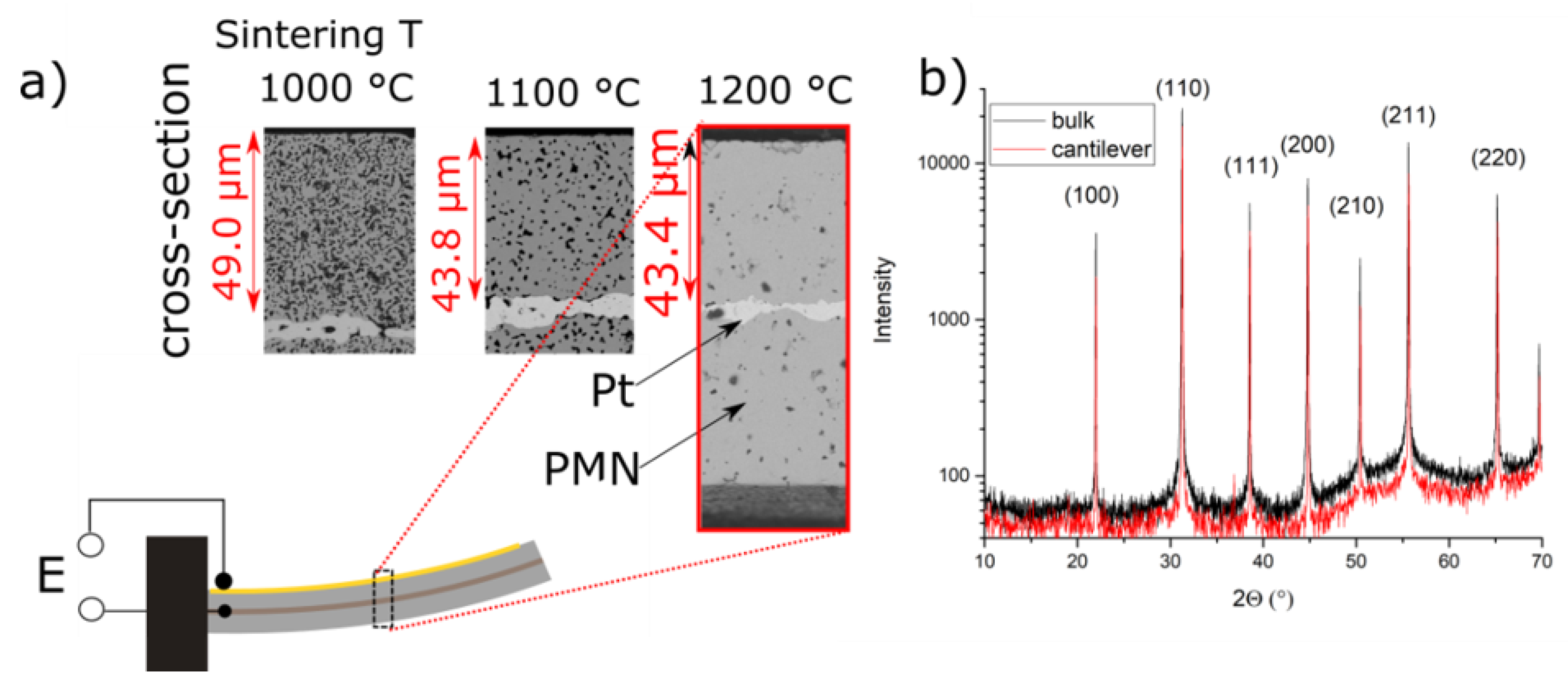
We first present the optimized microstructure of the sintered cantilevers. For optimization purposes, the cantilevers were sintered at three different temperatures of 1000 °C, 1100 °C and 1200 °C; the microstructures and the corresponding layer thicknesses are shown in Figure 2a. The optimal sintering temperature for obtaining dense ceramic films was 1200 °C, which is in agreement with previous studies on PMN-xPT [35,36]. The cantilevers prepared under such conditions possessed a dense and homogeneous microstructure (see Figure 2a, 1200 °C). The thickness was estimated from the micrographs and was 43 μm for the single PMN layer and 4 μm for the platinum layer.
XRD analyses were used to assess the phase composition of the sintered cantilevers and bulk ceramics, as shown in Figure 2b. The XRD analyses indicated a pseudo-cubic crystal structure, as expected for the PMN at room temperature and zero electric field. No secondary phases were detected, confirming the phase purity of the prepared PMN.
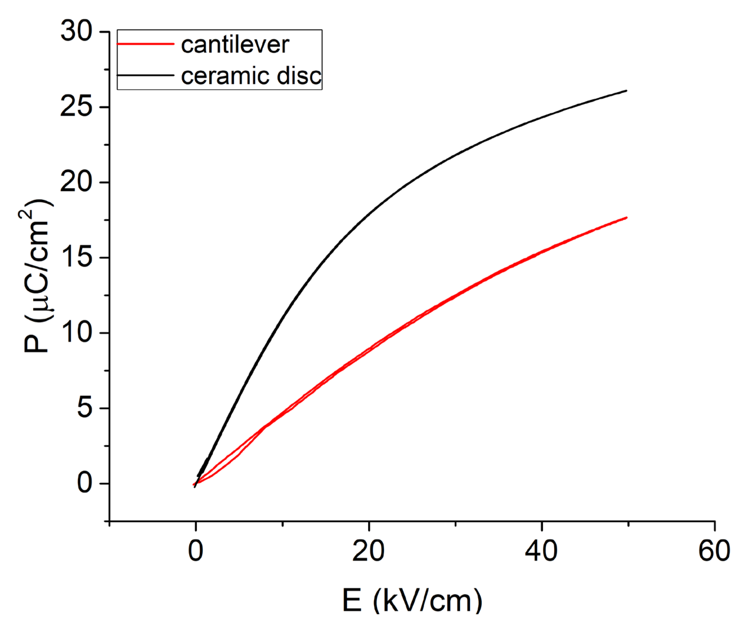
After the fabrication of the cantilevers, unipolar P(E) loops were measured, which gave an indication of the suitability of the PMN/Pt/PMN cantilever structure for EC applications. In principle, the change in P is related to the entropy change under an applied electric field and thus to the magnitude of the EC effect [37]. For comparison, the P(E) loop of the PMN ceramic sample is shown in addition to the PMN cantilever response in Figure 3. Both loops were measured under a unipolar electric field of 50 kV/cm to mimic the excitation conditions in the actual EC cooling device. Both loops showed a small hysteresis, as expected for the PMN at room temperature. The maximum polarization value of the bulk ceramic samples at 50 kV/cm was 26 μC/cm2, while that of the cantilevers was 17 μC/cm2 (i.e., 35% lower) The difference in the magnitude of the polarization could be related to several effects present in the thick films: (i) the clamping effect and mechanical stresses caused by the bottom inactive PMN layer [38], (ii) the surface quality of the tape-casted films and the influence of the interfacial layer between the Pt-electrode and the PMN layer [39,40] and (iii) the different sintering times, which can affect the microstructure and chemical homogeneity [41].
The electrical losses are proportional to the area of the P(E) loops [12]. High losses lead to self-heating effects under applied cyclic fields, which are detrimental to the EC cooling [13]. In Figure 3 it is shown that the loops of ceramic and the cantilever sample exhibit a small hysteresis area and thus low losses, meaning that small self-heating effects are expected [13], validating the choice of the PMN composition from among the PMN-xPT series and confirming previous findings on energy management in PMN-xPT material system [16].
The heat from the heat source to the heat sink in the proposed device is transferred by the bending and contacting of the cantilevers. Thus, the EM properties must be evaluated. When an electric field is applied to a cantilever, the active layer tends to contract due to the electromechanical response; however, its deformation is constrained by the electrode and the inactive PMN layer underneath the active PMN layer (see Figure 2a, inset). The induced stresses lead to bending of the cantilever, the magnitude of which is determined by the transverse EM response (perpendicular to the applied electric field (E3)) [31].
The deflection of the cantilever was measured in the electric field range between 10 kV/cm and 60 kV/cm at a field frequency of 0.1 Hz. At the maximum electric field of 60 kV/cm a deflection of 350 μm was measured (see red curve and left-hand axis in Figure 4). The estimated values, obtained using Equation (1), range from 7 pm/V at 10 kV/cm to 21 pm/V at 60 kV/cm (Figure 4, pink curve, right-hand axis). The values obtained were compared with the values obtained for a ceramic sample (Figure 4, black curve, right-hand axis), which are in the range between 35 pm/V at 10 kV/cm and 55 pm/V at 40 kV/cm, and consistent with the literature [42]. The results thus show that the cantilevers possess a lower transverse EM response compared to the ceramics. The lower EM response of the cantilever can be attributed to the clamping by the inactive (passive) volume of the cantilever structure and is consistent with the observed lower polarization values [40].
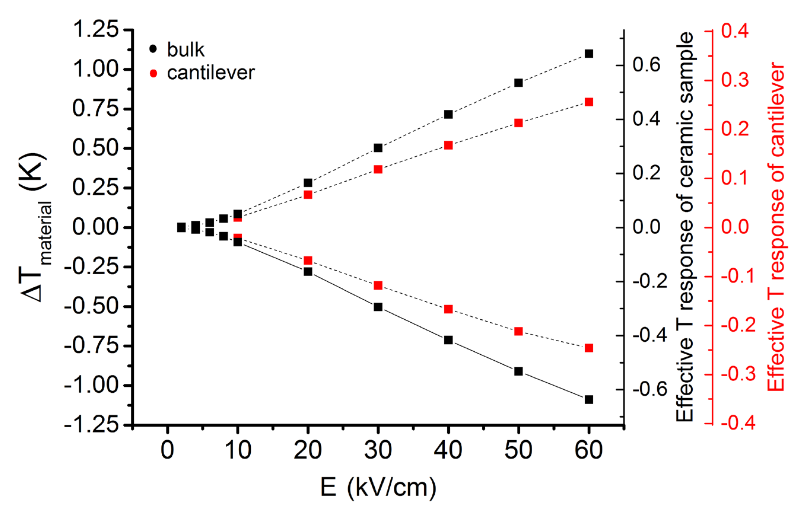
The EC temperature change is the most relevant property when designing an EC cooler. We analysed the EC effect of the cantilevers and compared it to that of the bulk ceramics. The corrected temperature changes, which reflect the response of the material itself (ΔTmaterial), are analysed first. The EC response of the material in the thick-film form (cantilever) is lower than the EC effect of bulk ceramics across the whole driving field range (Figure 5, left-hand vertical scale), which is in accordance with the lower P values exhibited by the PMN cantilevers (see Figure 2). As seen in Figure 5, the difference in the EC response increases with an increasing field magnitude. For example, at 10 kV/cm the PMN thick film in the cantilever exhibits an EC temperature change of 0.07 K, which is similar to that of the PMN in the bulk ceramic form (0.09 K). In contrast, at 60 kV/cm the cantilever’s PMN shows an EC effect of 0.76 K, which is smaller than that of the bulk ceramics by ~30% (1.09 K).
From the point of view of the applications, the cooling performance of the device is defined by the effective temperature change of the structure [43], and not directly by the EC temperature change inherent to the material. As shown in Figure 5 with the right-hand vertical axes for the ceramic and cantilever samples, the cantilevers possess a significantly smaller absolute EC effect (0.2 K at 60 kV/cm) than the bulk ceramic discs (0.65 K at 60 kV/cm) due to the larger proportion of inactive area. In fact, the bulk sample consists of 41% of inactive mass (non-electroded part of the sample, wires and thermistor), while in the case of the cantilever, this inactive part accounts for 69%, due to the thick-film Pt electrode, the additional non-active PMN layer, wires and thermistor. Therefore, while there is room for optimization of the cantilevers’ EC performance by decreasing the EC-inactive parts, paradoxically, this inactive area is mandatory to induce bending of the cantilever structure [31]. An optimization is thus inevitable. Alternatively, an interesting solution for reducing the fraction of the inactive mass of the sample without strongly reducing the bending performance of the cantilever would be to prepare ceramics with a compositional gradient [44] or a carefully engineered electron-energy band structure [45]. In these two cases, the passive (or oppositely poled) layer in an unimorph, usually needed to induce the cantilever bending, is avoided by creating conditions for a heterogeneous distribution of the electric field inside the cantilever. In the case of the compositional gradient concept, this is achieved by creating a compositional gradient along the thickness of the structure, while the second case of the energy band structure is benefiting from the semiconductive properties of ceramics, where combining different work functions of materials creates a diode effect. When the electric field is applied in the reverse direction, a gap is created, leading to an inhomogeneous distribution of the electric field that ultimately results in a bending motion.
After the characterization of the cantilevers, the cooling capability of the cantilevers was tested in a proof-of-concept device. Two cantilever elements were integrated into a special 3D printed holder, as shown schematically in Figure 1. The holder was designed in such a way that the adjacent slots for the placement of the cantilevers had a spacing smaller than the deflection of the cantilever under an electric field. The estimated spacing was 250 μm.
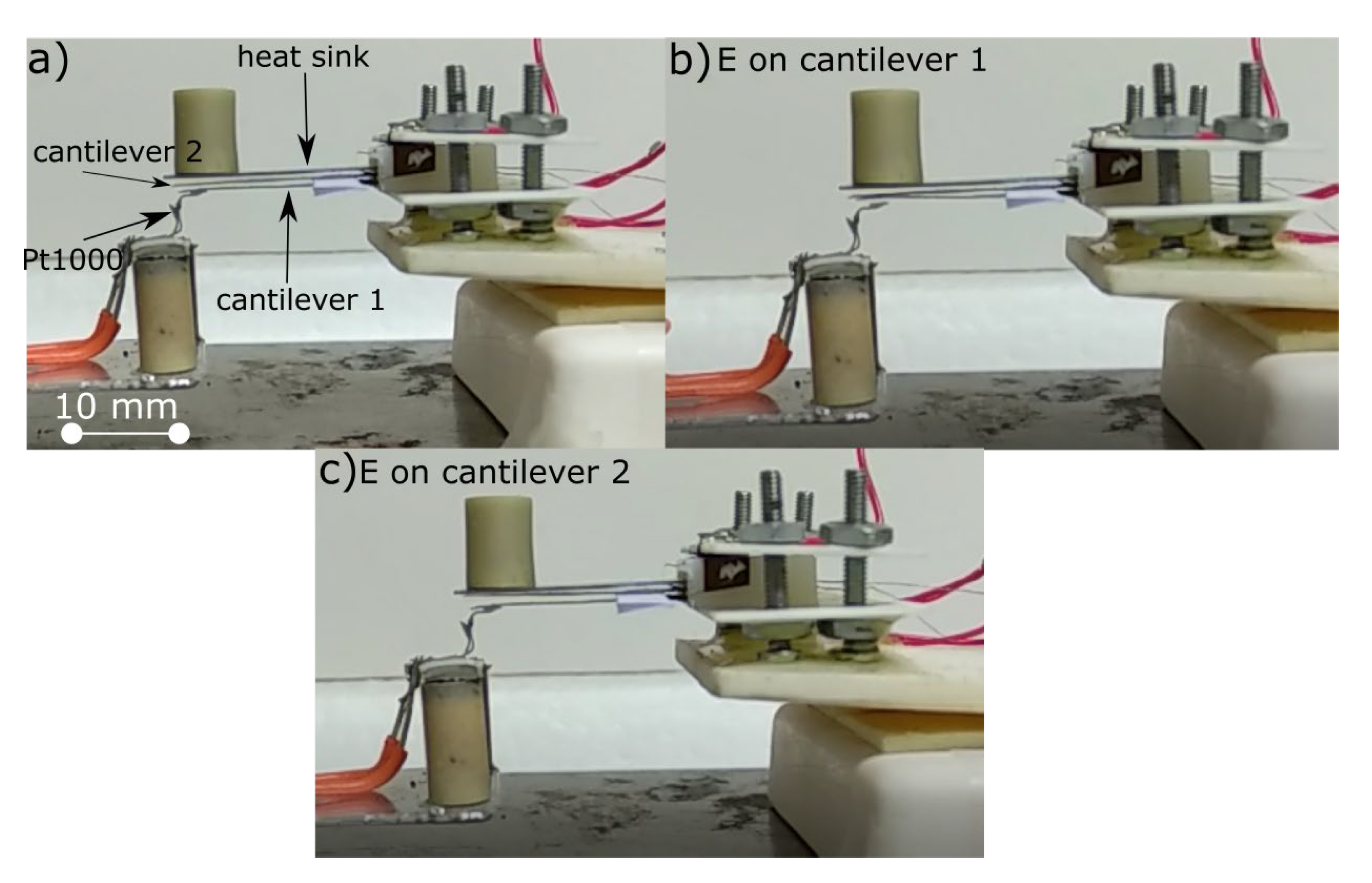
In the first place, we performed the analysis with one active cantilever, shown as cantilever 1 in the schematic of Figure 1 and Figure 6a. We cycled this cantilever with a unipolar square waveform magnitude of 45 kV/cm and within a frequency range from 0.2 Hz to 6 Hz. When the cantilever was cycled, it periodically contacted the heat source (in this case the thermistor, see Figure 1) and the heat sink (in this case, cantilever 2, see Figure 1). The proof-of-concept device and its operation with only cantilever 1 active is shown in Figure 6a,b.
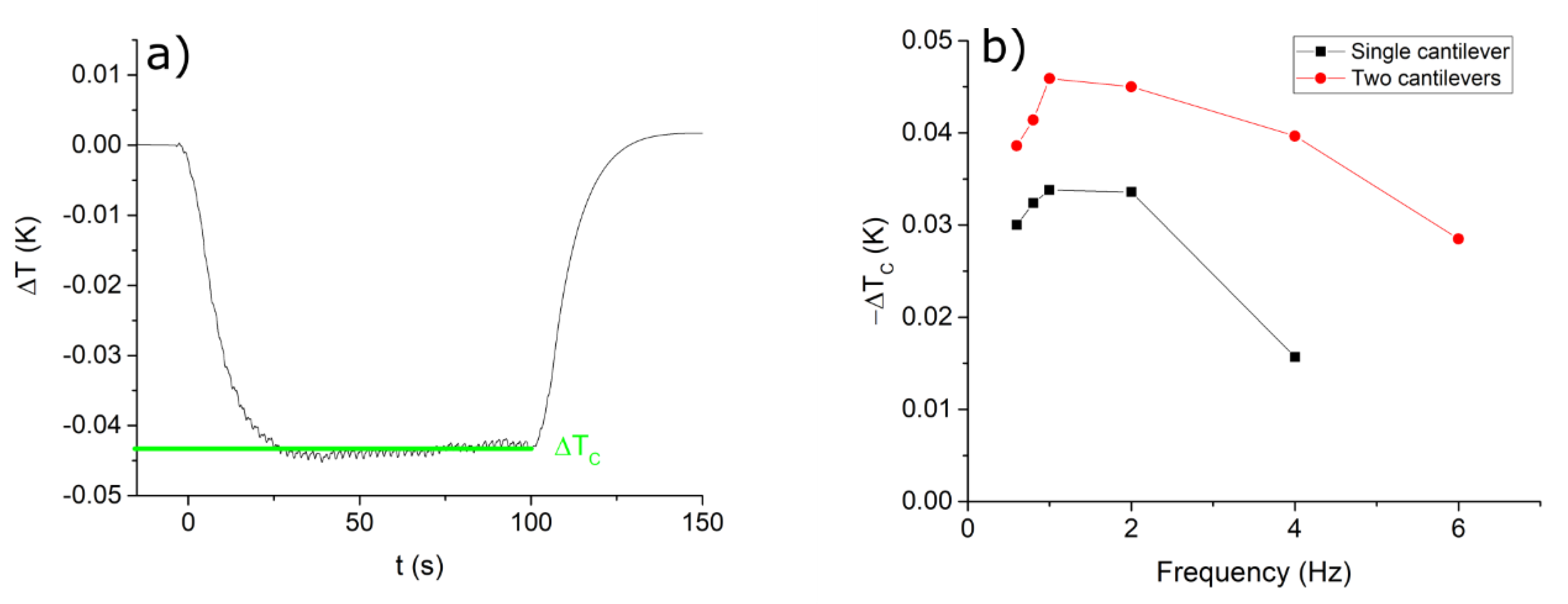
The test was then repeated, but with both cantilevers active. This case is shown in Figure 6a–c. After several field cycles, a stationary state was achieved. In the case of two cantilevers active, the sample needed 28 s to reach a stationary temperature, defined as the ΔTC at the specific field applied, as shown in Figure 7a.
The stationary temperature was determined for each driving frequency and for both cases of one or two cantilevers being active. The results are shown in Figure 7b and clearly show that the maximum temperature drop in both cases is close to 1–2 Hz. At frequencies lower than the optimum, the heat dissipation to the environment prevails over the heat transfer to the thermistor, which means the cooling effect is smaller. At higher frequencies than the optimum of 1–2 Hz, the thermal contact resistance inhibits the heat transfer between the cantilevers and heat sink and the heat source, which again led to the prevalence of heat exchange to the environment, reducing the effective cooling capability of the devices. Importantly, the results clearly confirmed a larger cooling effect by increasing the number of cantilevers (compare the black and red curves in Figure 7b), validating the earlier theoretical predictions [26].
The maximum temperature drop for the device is significantly smaller than the EC effect of the material (compare Figure 7b and Figure 5), thus no AER is achieved within the device under these conditions. This is for two reasons. First, in our previous theoretical study we showed that to achieve AER the optimum frequency of operation must be above 50 Hz for cantilever dimensions similar to the case shown here. In this design of the device we are thus limited by the poor thermal contacts between the cantilevers, which is particularly apparent as the driving frequency is increased (less time for an efficient thermal transfer). The thermal contacts are poor due to the surface roughness of the cantilevers and the bending radius of the cantilevers, which both reduce the contact area. Second, modelling showed that under realistic conditions, a certain critical amount of EC active volume is needed to overcome the losses to the environment through the surfaces of the cantilevers [26].
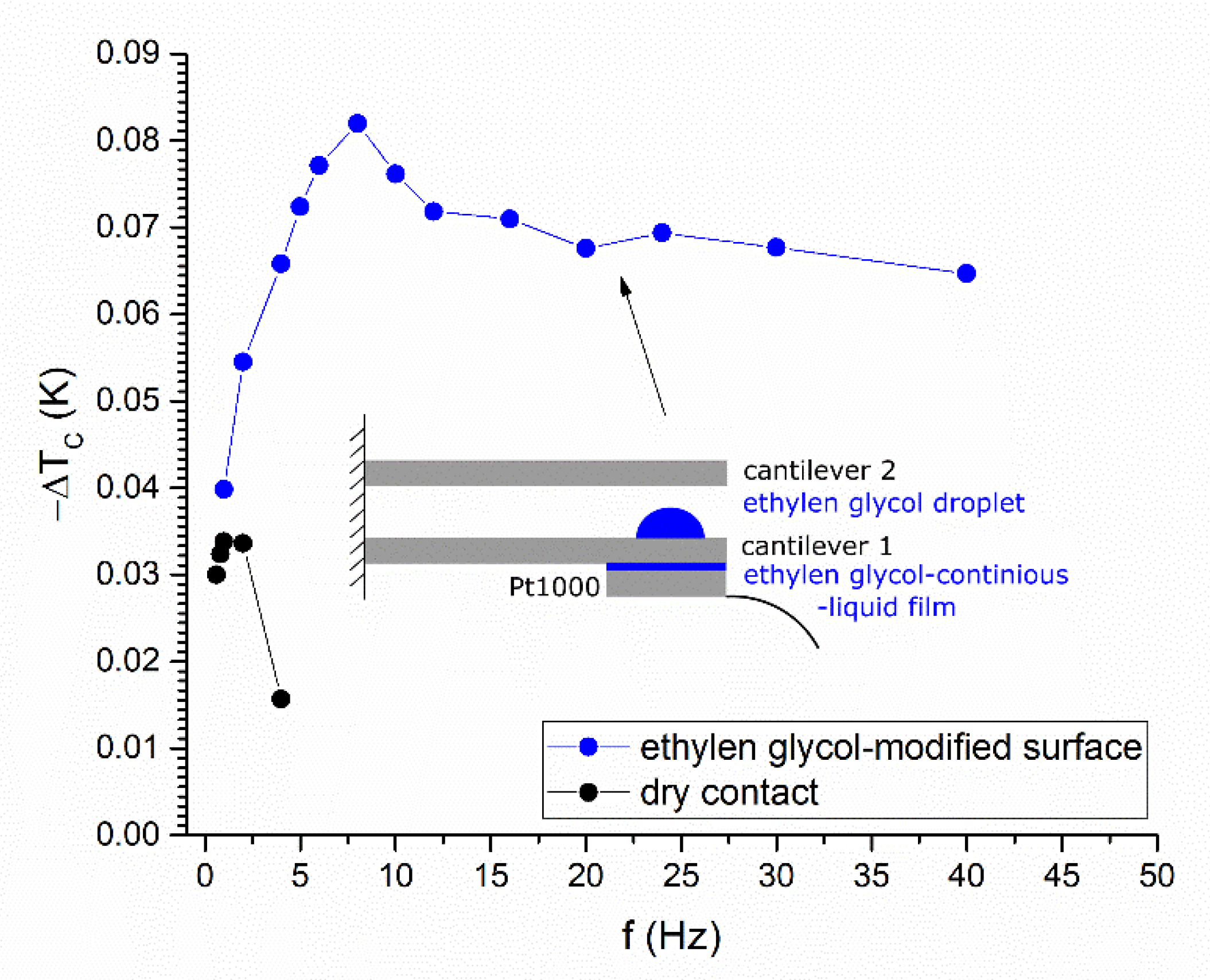
In the next step, as a demonstration of the solution to the thermal contact problem, we perform a proof-of-concept experiment to explore the influence of the thermal contact resistance. To improve the contact resistance, a droplet of ethylene glycol was applied on the surfaces of the single cantilever (see schematic in Figure 8) and the experiment described above (Figure 6a,b) was repeated. Upon contact, the droplets should undergo a reversible morphological transition into a continuous liquid film and ideally form a low-thermal-resistance contact area [46]. A significant improvement was observed with such a modification of the cantilevers’ surfaces. The temperature drop was 2.4-fold larger than in the case of the dry contact (compare the blue and black curves in Figure 8), reaching values of −ΔTC = 0.081 K at 8 Hz. In addition, the temperature drop is stable over a larger frequency range, with the maximum −ΔTC observed at a higher frequency (8 Hz) than the case with no ethylene glycol.
The drawback of the thermally conductive liquid used is the break-down of the samples, which was sporadically observed during several repeated driving tests. Since the droplets are not sufficiently pinned to the surface of the cantilever, the break-down of the samples is probably caused by the liquid wetting, especially at high driving frequencies, causing uncontrolled short circuits. While this would have to be improved, the experiments nevertheless clearly showed that the thermal contacts are one of the key parameters to be engineered for upgrading these cooling devices to the next stage of development.
With the experiments conducted so far, we have shown that the coupling of the EM and EC responses is feasible, but under the condition that the surface thermal contacts are tamed. As shown by our study, a challenging issue in such a device design is the thermal contacts between the ceramic samples, which are rigid and do not adapt and deform to the adjacent, contacting surface. In the literature, for example in [27,47], polymer calorics are often used, which are less rigid and have the ability to electrostatically stick to the surface of the heat sink and source by adapting their shape. For the rigid and brittle EC ceramics such an adaptation is not possible. However, ceramics have a particular advantage over polymers, being better thermal conductors (e.g., the specific thermal conductivity of PMN is 1.25 W/mK [29] compared to ~0.26 W/mK for PVDF-based materials [48]).

4. Summary and Conclusions

In this work we have fabricated, characterized and analysed PMN-based unimorph cantilevers consisting of PMN/Pt/PMN layers. Such cantilevers are an essential building block of the cooling device designed here that exploits the multifunctional nature of PMN, i.e., the electromechanical (EM) and electrocaloric (EC) functionality, to enable concurrent thermal contacts by EM bending and the cooling capability based on the EC effect. To evaluate the performance of the fabricated cantilevers, we first measured the electrical properties. The polarization–electric-field loops were slim, with small electrical losses compared with typical ferroelectrics. The PMN/Pt/PMN cantilever structure exhibited lower polarization values in comparison to their bulk counterparts for the same applied electric field, which was ascribed to the different conditions for the preparation of the samples and the effect of the inactive PMN layer in the cantilever’s structure. The deflections of the cantilevers under an applied electric field were in the 100s-of-micrometres range and thus promising for the fabrication of a cascade structure of such cantilevers, which can contact each other upon the application of an alternating electric field. The EC effect of the cantilevers was relatively low, mainly due to the design of the cantilever’s structure, because approximately 70% of the element did not contribute to the temperature change. Several solutions to improve the design of the cantilevers was proposed. We then exploited these cantilevers to illustrate the proof-of-concept device that uses multifunctional cantilevers for cooling. We clearly show that the cooling effect of the device can be increased by increasing the number of cantilever elements, validating our previous models and giving an important parameter to adjust the performance of the device. However, the cooling effect was lower than the effect of the single cantilever because of the poor thermal contacts. Although the effect of cooling was still too low because of the low thermal mass of the device structure, the experiment using ethylene glycol showed significantly improved thermal contacts. In the future, other methods for improving the thermal contacts will have to be considered and the number of elements will have to be increased to increase the cooling effect. We believe this study provides guidelines in this direction and we hope future studies will further develop the cooling capability of multifunctional cooling devices.

Author Contributions

Conceptualization of the paper was done by B.M. and T.R.; XRD and SEM analysis was done by M.O.; Electrical, electromechanical and electrocaloric characterization, A.B., L.F., M.V., J.K.; A.B. fabricated the proof-of-concept device; A.M. prepared solutions for surface modification; A.B. & T.R. wrote the manuscript; All author reviewed, edited and agreed to the published version of the manuscript. All authors have read and agreed to the published version of the manuscript.

Funding

The authors thank the Slovenian Research Agency for financial support in the frame of the doctoral project of Andraž Bradeško, projects J2-7526, PR-08298 (contract number BI-DE/18-19-007), L2-8180, and program P2-0105.

Institutional Review Board Statement

Not applicable.

Informed Consent Statement

Not applicable.

Acknowledgments

A.B. thanks Silvo Drnovšek, Jena Cilenšek, Brigita Rožič, and Zdravko Kutnjak for fruitful discussions and help in the laboratory.

Conflicts of Interest

The authors declare no conflict of interest.

References

  1. Kutnjak, Z.; Rožič, B.; Pirc, R. Electrocaloric Effect: Theory, Measurements, and Applications. In Wiley Encyclopedia of Electrical and Electronics Engineering; John Wiley & Sons, Inc.: Hoboken, NJ, USA, 2015; pp. 1–19. [Google Scholar]
  2. Scott, J.F. Electrocaloric Materials. Annu. Rev. Mater. Res. 2011, 41, 229–240. [Google Scholar] [CrossRef]
  3. Mischenko, A.S.; Zhang, Q.; Scott, J.F.; Whatmore, R.W.; Mathur, N.D. Giant electrocaloric effect in thin-film PbZr0.95Ti0.05O3. Science 2006, 311, 1270–1271. [Google Scholar] [CrossRef] [PubMed] [Green Version]
  4. Correia, T.; Zhang, Q. Electrocaloric Materials; Correia, T., Zhang, Q., Eds.; Engineering Materials; Springer: Berlin/Heidelberg, Germany, 2014; Volume 34, ISBN 978-3-642-40263-0. [Google Scholar]
  5. Lu, S.G.; Rožič, B.; Zhang, Q.M.; Kutnjak, Z.; Li, X.; Furman, E.; Gorny, L.J.; Lin, M.; Malič, B.; Kosec, M.; et al. Organic and inorganic relaxor ferroelectrics with giant electrocaloric effect. Appl. Phys. Lett. 2010, 97, 162904. [Google Scholar] [CrossRef]
  6. Nair, B.; Usui, T.; Crossley, S.; Kurdi, S.; Guzmán-Verri, G.G.; Moya, X.; Hirose, S.; Mathur, N.D. Large electrocaloric effects in oxide multilayer capacitors over a wide temperature range. Nature 2019, 575, 468–472. [Google Scholar] [CrossRef]
  7. Neusel, C.; Schneider, G.A. Size-dependence of the dielectric breakdown strength from nano- to millimeter scale. J. Mech. Phys. Solids 2014, 63, 201–213. [Google Scholar] [CrossRef] [Green Version]
  8. Otoničar, M.; Bradeško, A.; Fulanović, L.; Kos, T.; Uršič, H.; Benčan, A.; Cabral, M.J.; Henriques, A.; Jones, J.L.; Riemer, L.; et al. Connecting the Multiscale Structure with Macroscopic Response of Relaxor Ferroelectrics. Adv. Funct. Mater. 2020, 30, 2006823. [Google Scholar] [CrossRef]
  9. Fu, D.; Taniguchi, H.; Itoh, M.; Mori, S. Pb(Mg1/3Nb2/3)O3 (PMN) Relaxor: Dipole Glass or Nano-Domain Ferroelectric? In Advances in Ferroelectrics; InTech: Rijeka, Croatia, 2012. [Google Scholar]
  10. Bokov, A.A.; Ye, Z.-G. Recent progress in relaxor ferroelectrics with perovskite structure. J. Mater. Sci. 2006, 41, 31–52. [Google Scholar] [CrossRef]
  11. Härdtl, K.H. Electrical and mechanical losses in ferroelectric ceramics. Ceram. Int. 1982, 8, 121–127. [Google Scholar] [CrossRef]
  12. Uchino, K.; Zheng, J.H.; Chen, Y.H.; Du, X.H.; Ryu, J.; Gao, Y.; Ural, S.; Priya, S.; Hirose, S. Loss mechanisms and high power piezoelectrics. J. Mater. Sci. 2006, 41, 217–228. [Google Scholar] [CrossRef]
  13. Zheng, J.; Takahashi, S.; Yoshikawa, S.; Uchino, K.; de Vries, J.W.C. Heat Generation in Multilayer Piezoelectric Actuators. J. Am. Ceram. Soc. 1996, 79, 3193–3198. [Google Scholar] [CrossRef]
  14. Liu, G.; Zhang, S.; Jiang, W.; Cao, W. Losses in ferroelectric materials. Mater. Sci. Eng. R Rep. 2015, 89, 1–48. [Google Scholar] [CrossRef] [Green Version]
  15. Bradeško, A.; Hedl, A.; Fulanović, L.; Novak, N.; Rojac, T. Self-heating of relaxor and ferroelectric ceramics during electrocaloric field cycling. APL Mater. 2019, 7, 071111. [Google Scholar] [CrossRef] [Green Version]
  16. Plaznik, U.; Vrabelj, M.; Kutnjak, Z.; Malič, B.; Poredoš, A.; Kitanovski, A. Electrocaloric cooling: The importance of electric-energy recovery and heat regeneration. Europhys. Lett. 2015, 111, 57009. [Google Scholar] [CrossRef]
  17. Shi, J.; Han, D.; Li, Z.; Yang, L.; Lu, S.G.; Zhong, Z.; Chen, J.; Zhang, Q.M.; Qian, X. Electrocaloric Cooling Materials and Devices for Zero-Global-Warming-Potential, High-Efficiency Refrigeration. Joule 2019, 3, 1200–1225. [Google Scholar] [CrossRef]
  18. Plaznik, U.; Kitanovski, A.; Rožič, B.; Malič, B.; Uršič, H.; Drnovšek, S.; Cilenšek, J.; Vrabelj, M.; Poredoš, A.; Kutnjak, Z. Bulk relaxor ferroelectric ceramics as a working body for an electrocaloric cooling device. Appl. Phys. Lett. 2015, 106, 043903. [Google Scholar] [CrossRef]
  19. Blumenthal, P.; Molin, C.; Gebhardt, S.; Raatz, A. Active electrocaloric demonstrator for direct comparison of PMN-PT bulk and multilayer samples. Ferroelectrics 2016, 497, 1–8. [Google Scholar] [CrossRef]
  20. Torelló, A.; Lheritier, P.; Usui, T.; Nouchokgwe, Y.; Gérard, M.; Bouton, O.; Hirose, S.; Defay, E. Giant temperature span in electrocaloric regenerator. Science 2020, 370, 125–129. [Google Scholar] [CrossRef]
  21. Gu, H.; Qian, X.; Li, X.; Craven, B.; Zhu, W.; Cheng, A.; Yao, S.C.; Zhang, Q.M. A chip scale electrocaloric effect based cooling device. Appl. Phys. Lett. 2013, 102, 122904. [Google Scholar] [CrossRef]
  22. Gu, H.; Qian, X.S.; Ye, H.J.; Zhang, Q.M. An electrocaloric refrigerator without external regenerator. Appl. Phys. Lett. 2014, 105, 162905. [Google Scholar] [CrossRef]
  23. Wang, Y.; Schwartz, D.E.; Smullin, S.J.; Wang, Q.; Sheridan, M.J. Silicon Heat Switches for Electrocaloric Cooling. J. Microelectromech. Syst. 2017, 26, 580–587. [Google Scholar] [CrossRef]
  24. Jia, Y.; Ju, Y.S. A solid-state refrigerator based on the electrocaloric effect. Appl. Phys. Lett. 2012, 100, 242901. [Google Scholar] [CrossRef]
  25. Wang, Y.; Zhang, Z.; Usui, T.; Benedict, M.; Hirose, S.; Lee, J.; Kalb, J.; Schwartz, D. A high-performance solid-state electrocaloric cooling system. Science 2020, 370, 129–133. [Google Scholar] [CrossRef] [PubMed]
  26. Bradeško, A.; Juričić, Đ.; Santo Zarnik, M.; Malič, B.; Kutnjak, Z.; Rojac, T.; Juričić, D.; Santo Zarnik, M.; Malič, B.; Kutnjak, Z.; et al. Coupling of the electrocaloric and electromechanical effects for solid-state refrigeration. Appl. Phys. Lett. 2016, 109, 143508. [Google Scholar] [CrossRef]
  27. Ma, R.; Zhang, Z.; Tong, K.; Huber, D.; Kornbluh, R.; Ju, Y.S.; Pei, Q. Highly efficient electrocaloric cooling with electrostatic actuation. Science 2017, 357, 1130–1134. [Google Scholar] [CrossRef] [Green Version]
  28. Meng, Y.; Zhang, Z.; Wu, H.; Wu, R.; Wu, J.; Wang, H.; Pei, Q. A cascade electrocaloric cooling device for large temperature lift. Nat. Energy 2020, 5, 996–1002. [Google Scholar] [CrossRef]
  29. Uršič, H.; Vrabelj, M.; Fulanović, L.; Bradeško, A.; Drnovsek, S.; Malič, B. Specific heat capacity and thermal conductivity of the electrocaloric (1 − x)Pb(Mg1/3Nb2/3)O3–xPbTiO3 ceramics between room temperature and 300 °C. J. Microelectron. Electron. Compon. Mater. 2015, 45, 260–265. [Google Scholar]
  30. Lide, D. CRC Handbook of Chemistry and Physics, 84th ed.; CRC Press: Boca Raton, FL, USA, 2005; Volume 86. [Google Scholar]
  31. Wang, Q.-M.; Cross, L.E. Performance analysis of piezoelectric cantilever bending actuators. Ferroelectrics 1998, 215, 187–213. [Google Scholar] [CrossRef]
  32. Ealey, M.A. Standard SELECT electrostrictive lead magnesium niobate actuators for active and adaptive optical components. Opt. Eng. 1990, 29, 1373. [Google Scholar] [CrossRef]
  33. Uršič, H.; Hrovat, M.; Holc, J.; Zarnik, M.S.; Drnovšek, S.; Maček, S.; Kosec, M. A large-displacement 65Pb(Mg1/3Nb2/3)O3–35PbTiO3/Pt bimorph actuator prepared by screen printing. Sens. Actuators B Chem. 2008, 133, 699–704. [Google Scholar] [CrossRef]
  34. Arduino Uno. Available online: https://www.arduino.cc/ (accessed on 23 December 2020).
  35. Vrabelj, M.; Uršič, H.; Kutnjak, Z.; Rožič, B.; Drnovšek, S.; Benčan, A.; Bobnar, V.; Fulanović, L.; Malič, B. Large electrocaloric effect in grain-size-engineered 0.9Pb(Mg1/3Nb2/3)O3–0.1PbTiO3. J. Eur. Ceram. Soc. 2016, 36, 75–80. [Google Scholar] [CrossRef]
  36. Dragomir, M.; Otoničar, M.; Vrabelj, M.; Fulanović, L.; Drnovšek, S.; Rojac, T.; Malič, B. Seeding effects on the mechanochemical synthesis of 0.9Pb(Mg1/3Nb2/3)O3–0.1PbTiO3. J. Eur. Ceram. Soc. 2019, 39, 1837–1845. [Google Scholar] [CrossRef]
  37. Pirc, R.; Kutnjak, Z.; Blinc, R.; Zhang, Q.M. Upper bounds on the electrocaloric effect in polar solids. Appl. Phys. Lett. 2011, 98, 4–7. [Google Scholar] [CrossRef]
  38. Griggio, F.; Jesse, S.; Kumar, A.; Ovchinnikov, O.; Kim, H.; Jackson, T.N.; Damjanovic, D.; Kalinin, S.V.; Trolier-Mckinstry, S. Substrate clamping effects on irreversible domain wall dynamics in lead zirconate titanate thin films. Phys. Rev. Lett. 2012, 108, 157604. [Google Scholar] [CrossRef] [PubMed]
  39. Ihlefeld, J.F.; Harris, D.T.; Keech, R.; Jones, J.L.; Maria, J.P.; Trolier-McKinstry, S. Scaling Effects in Perovskite Ferroelectrics: Fundamental Limits and Process-Structure-Property Relations. J. Am. Ceram. Soc. 2016, 99, 2537–2557. [Google Scholar] [CrossRef]
  40. Lee, H.J.; Zhang, S.; Luo, J.; Li, F.; Shrout, T.R. Thickness-dependent properties of relaxor-PbTiO3 ferroelectrics for ultrasonic transducers. Adv. Funct. Mater. 2010, 20, 3154–3162. [Google Scholar] [CrossRef] [PubMed] [Green Version]
  41. Leite, E.R.; Scotch, A.M.; Khan, A.; Li, T.; Chan, H.M.; Harmer, M.P.; Liu, S.-F.; Park, S.-E. Chemical Heterogeneity in PMN-35PT Ceramics and Effects on Dielectric and Piezoelectric Properties. J. Am. Ceram. Soc. 2004, 85, 3018–3024. [Google Scholar] [CrossRef]
  42. Nomura, S.; Uchino, K. Electrostrictive effect in Pb(Mg 1/3 Nb 2/3)O 3 -type materials. Ferroelectrics 1982, 41, 117–132. [Google Scholar] [CrossRef]
  43. Greiner, A.; Molin, C.; Neubert, H.; Gebhardt, S.E.; Neumeister, P. Direct Measurement of the Electrocaloric Temperature Change in Multilayer Ceramic Components using Resistance-Welded Thermocouple Wires. Energy Technol. 2018, 6, 1535–1542. [Google Scholar] [CrossRef]
  44. Wu, C.C.M.; Kahn, M.; Moy, W. Piezoelectric Ceramics with Functional Gradients: A New Application in Material Design. J. Am. Ceram. Soc. 2005, 79, 809–812. [Google Scholar] [CrossRef]
  45. Uchino, K.; Yoshizaki, M.; Kasai, K.; Yamamura, H.; Sakai, N.; Asakura, H. “Monomorph Actuators” Using Semiconductive Ferroelectrics. Jpn. J. Appl. Phys. 1987, 26, 1046–1049. [Google Scholar] [CrossRef]
  46. Jia, Y.; Cha, G.; Ju, Y.S. Switchable Thermal Interfaces Based on Discrete Liquid Droplets. Micromachines 2012, 3, 10–20. [Google Scholar] [CrossRef] [Green Version]
  47. Almanza, M.; Depreux, L.; Parrain, F.; Lobue, M. Electrostatically actuated thermal switch device for caloric film. Appl. Phys. Lett. 2018, 112, 083901. [Google Scholar] [CrossRef] [Green Version]
  48. Dos Santos, W.N.; Iguchi, C.Y.; Gregorio, R. Thermal properties of poly(vinilidene fluoride) in the temperature range from 25 to 210 °C. Polym. Test. 2008, 27, 204–208. [Google Scholar] [CrossRef]
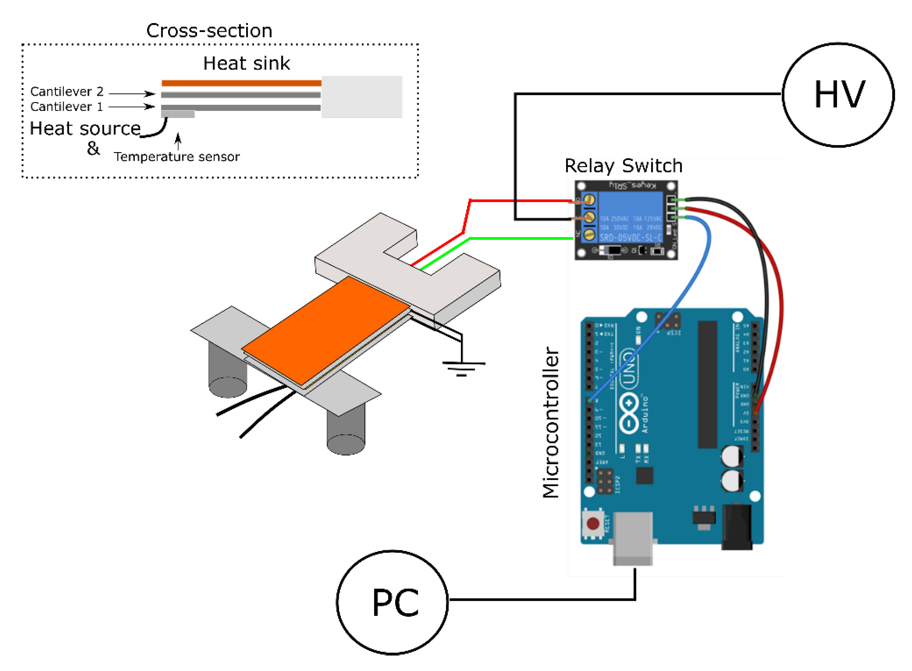
Figure 1. Experimental setup for testing the proof-of-concept device. The cantilevers were arranged in a cascade structure as shown in the inset (dashed box). From bottom to top the structure was arranged in the following order (see dashed box): heat source, cantilever 1, cantilever 2 and heat sink. The electric field applied to the two cantilevers was managed by a microcontroller circuit that controllably applied the voltage potential from the high-voltage source to the cantilevers in a repeating sequential manner. The schematic is not to scale. (Edited after Ref. [34]).
Actuators 10 00058 g001
Figure 2. (Micro)structure of the cantilever sample used in the study. (a) SEM micrographs showing the microstructures of the three cantilevers sintered at three different temperatures. As shown in the bottom-most inset, the cantilever consisted of three layers, i.e., PMN, Platinum (Pt) and another PMN layer. When an electric field (E) is applied to the upper PMN layer, the cantilever bends, as shown schematically in the bottom inset). (b) XRD patterns of PMN in the bulk ceramic and cantilever form. Both show a pseudo-cubic perovskite structure with no secondary pyrochlore phases.
Actuators 10 00058 g002
Figure 3. Unipolar polarization–electric-field (P(E)) loops of PMN ceramics and cantilevers, measured at 50 kV/cm and 1 Hz.
Actuators 10 00058 g003
Figure 4. Electromechanical response of PMN ceramics and PMN-based cantilever. Tip displacements (δ) of the cantilever versus electric field (E3) are shown as red points with the scale of the displacements given on the left-hand vertical axis. The values were used to calculate the −s1/E3 values (pink symbols), which were then compared with bulk ceramics (black symbols) of the same PMN composition.
Actuators 10 00058 g004
Figure 5. EC effect of bulk ceramics (black) and cantilevers (red). Left vertical axis shows the corrected values, i.e., materials response (ΔTmaterial), while the right axis displays the effective temperature change (note two scales for the ceramic and cantilever samples).
Actuators 10 00058 g005
Figure 6. Snapshots of the proof-of-concept device. (a) Initial state of the cantilevers when no electric field is applied. Cantilever 1 is in contact with the Pt1000, which acts as a heat source and as a temperature sensor at the same time. The upmost cantilever is the heat sink. The cylinder on the top of this cantilever was used to damp the vibrations of the structure. (b) State when the electric field is applied to cantilever 1. As a consequence, cantilever 1 bends and makes a contact with cantilever 2. (c) State when the electric field is applied to cantilever 2, which bends and makes contact with the heat sink (the uppermost inactive cantilever).
Actuators 10 00058 g006
Figure 7. Performance of the proof-of-concept device. (a) Time evolution of the temperature of the heat source (represented by the Pt1000 temperature sensor) during cycling with 45 kV/cm and 2 Hz. The case is for two cantilevers being active. The green line denotes the equilibrated temperature drop—ΔTC. (b) ΔTC obtained at different frequencies with one active cantilever (black curve) and two active cantilevers (red curve) in the cascade.
Actuators 10 00058 g007
Figure 8. Improving the thermal contacts as a proof-of-concept experiment. The surface of cantilever 1 was modified using ethylene glycol. The blue curve shows the frequency dependence of the temperature drop on the thermistor (heat source) when ethylene glycol is used (the case for cantilever 1 active). It is evident that the ethylene glycol droplets improved the contact and increased the temperature drop compared to the dry contacting (black).
Actuators 10 00058 g008
Publisher’s Note: MDPI stays neutral with regard to jurisdictional claims in published maps and institutional affiliations.