Abstract
To improve the accuracy, rapidity, and versatility of pneumatic control valves, mechanism modeling, and optimization analysis on pneumatic actuators were carried out, and then a new positioning strategy based on parameter tuning and optimal control technique was proposed consequently. Firstly, a dynamic model of valve position based on optimal control under constraint conditions was established, and the characteristic parameters of valve position motion were determined. Then, the adaptive processing of switching points was introduced into the optimal control strategy to improve the versatility of the control. Finally, according to different control strategy partitions, the interactive control of the piezoelectric air switch by fully open control and PWM improves the control accuracy of the algorithm. The experimental analysis of the control effect with other brand positioners shows that the proposed control strategy shortens the system adjustment time, improves the accuracy of valve position, and avoids the overshoot.
1. Introduction
A pneumatic control valve is an important part of the process control system, which is composed of a valve positioner, an actuator, and a valve. It is widely used in petroleum, pharmaceutical, chemical, thermal, material, and light industry fields. The valve positioner is the core component of the pneumatic control valve, which plays a decisive role in the positioning of the control valve [1,2,3,4]. According to the different classifications of the input signals, the valve positioner is classed as a pneumatic valve positioner, an electropneumatic valve positioner, or an intelligent valve positioner [5,6]. In the 1990s, Fisher launched the first generation of intelligent valve positioner DVC series products, which greatly improved the working performance of the valve and occupied a large market share as soon as it was launched [7,8,9,10]. Compared with traditional valve positioners, intelligent valve positioners have the characteristics of high reliability, high control accuracy, easy expansion of functions, and communication capabilities, and have become the focus of research on positioners [11,12,13]. According to the working principle of the I/P (input/power) conversion unit, intelligent valve positioners are divided into nozzle baffle valve positioners and piezoelectric valve positioners [14,15,16]. Among them, piezoelectric materials have the characteristics of high reliability, low power consumption, and low gas consumption during operation, and gradually became the mainstream of the electrical conversion components market of valve positioners in recent years [17,18,19,20,21].
The performance of the intelligent valve positioner not only depends on the hardware, but the internal control algorithm is the most important thing. The control algorithms are mainly divided into five-step switch control and PID control with an optimization method. In 2004, based on the traditional PID control algorithm, Liang [22] adopted an intelligent valve positioner with a 4–20 mA two-wire signal, and proposed a self-learning fuzzy controller for the imitation integral rule. In 2013, Jin [23] adopted segmented PID control combined with the self-tuning method of online identification. The result showed that the precise control of valve position was realized. In 2018 [9], Wang Kaibin proposed a neural-network-based, dual-closed-loop-system, PID, parameter-tuning control algorithm. Through the neural network model, the PID tuning parameters were obtained, and an experimental platform was built to verify the effectiveness of the control algorithm, which was performed with SVP300 series intelligent valve positioners. The analysis and comparison showed that the algorithm is better than SVP300 in terms of rapidity. In 2020 [11], Lu Yangkang conducted a large number of simulation analyses for the non-linear characteristics of the positioner. Using the inner membrane control method (IMC) as the parameter self-tuning rule, B-B control, and PID segmented controller as the closed-loop control strategy, can eliminate the integral saturation linearity. In 2021 [24], Ma Zhihang adopted an adaptive immune fuzzy PID control algorithm, first by realizing the parameter self-tuning of the pneumatic actuator, and then by building the simulation circuit and establishing the transfer function of each part of the actuator. The results show that the adjustment time of the control system only needs 0.6 s.
However, the conventional PID algorithm has difficulties in parameter adjustment and high requirements for system dynamics. The traditional five-step switch algorithm is simple and easy to understand, easy to implement, and fast at positioning [25]. In 2009, the SIPART P32 electric valve positioner was developed by German SIEMEN [26], which combines Bang-Bang control and PWM control. It is said that the control precision achieved 0.2%, but the specific parameters and algorithm details were unknown. In 2011, Liu [27] proposed a linear duty cycle strategy with valve position feedback to improve the positioning speed of the valve position, aiming at the situation that the five-step switching control algorithm created a shock at low valve positions, and the control cycle of high valve position was long. In the same year, Xu [28] further improved the duty cycle strategy, which was linear with valve position feedback, and proposed a parameter self-tuning method before closed-loop control of the control valve, which could obtain the “optimal PWM” of any valve position in advance. At the same time, the five-step switching interval is further divided into a fast zone, deceleration zone, fine-tuning zone, and dead zone according to other parameters of auto-tuning, and different zones are controlled by different optimal duty ratios. In 2012, Liu [29] combined the five-step switching control idea with the PID control algorithm, and also proposed a strategy of pre-tuning control parameters of control valve. The results showed that the algorithm achieved valve position positioning accuracy of ±1% FSR (full scale range). In 2014, Xu [25] re-divided the originally designed fine-tuning zone into a safety zone based on the minimum valve position change in unit time, and adjusted the expected valve position velocity of duty ratio in the zone. The results showed that the valve position could move quickly to the target position without overshoot. In 2016, Li [30] explored the principle of compensating lag time PWM (pulse width modulation) control and Bang-Bang control, and proposed a three-step zero elimination control algorithm, on the basis of which the zero dead zone could be eliminated by switching on/off control valve for only three times. The experimental results showed that the control precision was very high and could greatly meet the high frequency response.
The above studies provide a lot of support and help for the research and development of high-performance intelligent valve positioners. However, the great differences between different control valves were seldom considered in the above research, especially the non-standardization of processing in the valve manufacturing industry. Therefore, a general control algorithm should be designed to improve the adaptability of the control of the positioner. We carried out modeling and optimization analysis on pneumatic actuators, analyzed the shortcomings of traditional five-step switch control, and propose a positioning strategy combining parameter tuning and an optimal control technique in an effort to achieve more stable and precise control of pneumatic control valves. Meanwhile, to analyze and compare different control algorithms, an intelligent performance detection device was specially designed and developed, and a set of experimental comparisons was performed to verify the performance of our proposed positioning strategy.
2. Modeling and Optimization Analysis of the Dynamics of Pneumatic Control Process
2.1. Dynamic Modeling of a Control Valve Pneumatic Actuator
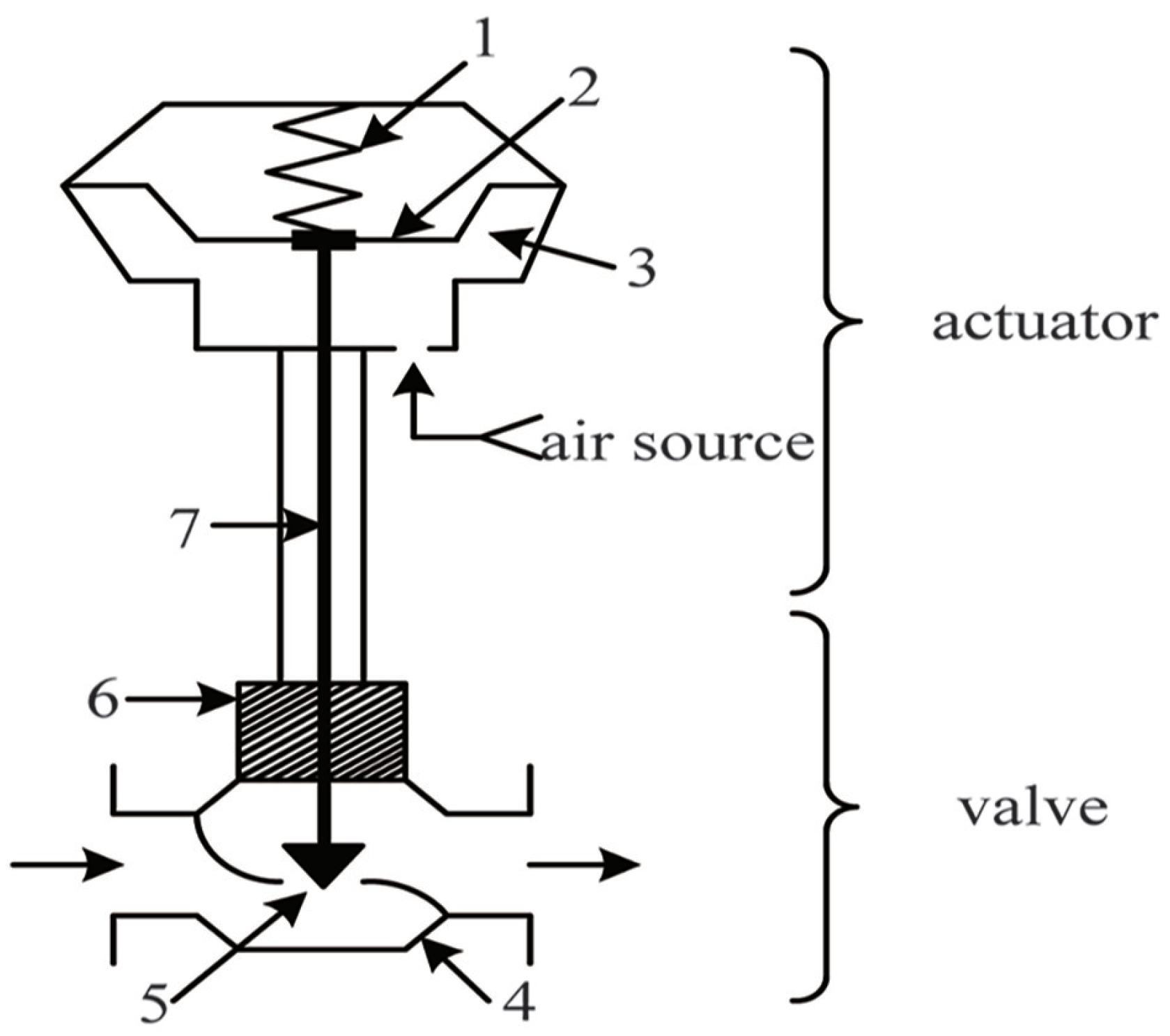
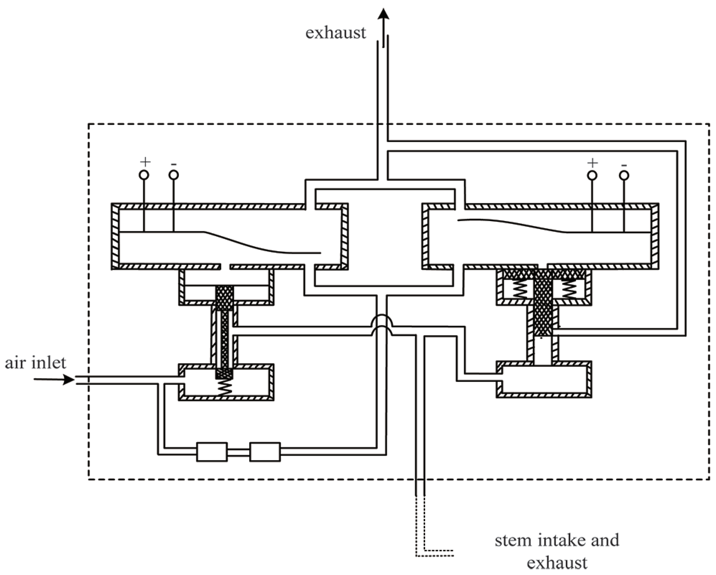
The up and down movement of the pneumatic valve stem is driven by high-pressure air intake or exhaust, as shown in Figure 1. The piezoelectric air switch is the pneumatic actuator of the pneumatic control valve, and its internal principle is shown in Figure 2. To ensure that the valve stem returns to its position after exhaust, a reset spring is specially set on the valve stem. The valve stem is affected by the spring tension, the high-pressure gas thrust in the cylinder, the friction between the valve stem and graphite packing, the weight of the valve stem, and impact of the flow medium of the valve body during the movement. Among them, the friction force is not only opposite to the movement direction of the stem, but also related to the cylinder pressure when the stem is stationary.
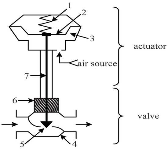
Figure 1.
Actuator of a pneumatic control valve. 1: reset spring; 2: thin film; 3: membrane chamber; 4: valve seat; 5: valve element; 6: stuffing box packing; 7: valve stem.
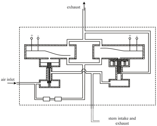
Figure 2.
Principle of a piezoelectric air switch device.
During the movement of the valve stem, the displacement in the vertical direction is considered, but the slight displacement in other directions is ignored. Regarding the valve stem as a mass, the valve stem is affected by five forces in total, as shown in Figure 3.
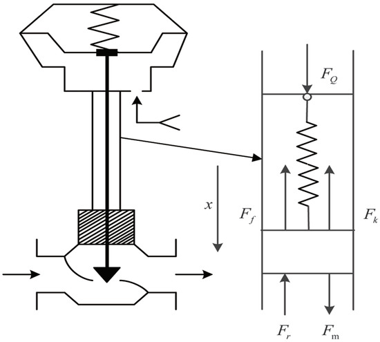
Figure 3.
Dynamic analysis of valve stem.
(1) the air thrust ; (2) the elasticity of the reset spring ; (3) the stem friction ; (4) the gravity on the stem and accessories ; (5) the fluid disturbance power .
According to Figure 3, for the regulating valve with intake air at the upper end of the valve cylinder, the dynamic equation of the force on the valve stem during the movement can be expressed as
When the valve stem is stationary,
Equation (1) represents the downward movement of the valve stem, and Formula (2) represents the upward movement of the valve stem. In the formula, t represents time and x represents the displacement or relative position of the valve stem. Although also represents friction, it is different from the dynamic situation and belongs to static friction, and its maximum value is several times that of the dynamic friction.
For the return spring, its force is related to the position, which can be expressed as:
where K is the elastic coefficient of the return spring, and is the deformation of the return spring without air intake.
The gravity of valve stem and accessories can be expressed as:
The open state of a single straight-through spool-regulating valve is shown in Figure 4. When the pressure difference on both sides of the valve core is fixed, the flow force of the valve core is related to the pressure and contact area of the valve core. It can be expressed as:
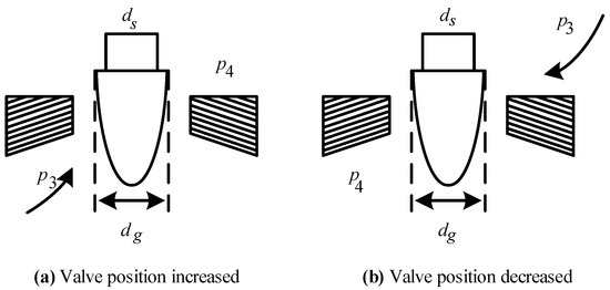
Figure 4.
Structure diagram of straight-through single-seat valve spool.
When the displacement of the valve spool is zero, the valve spool is fully closed. The cross-sectional area of the valve spool is also the largest and the flow force is the largest. It can be expressed as:
Under normal circumstances, its size is much smaller than the return spring force and aerodynamic thrust, and it can generally be regarded as the disturbance of the equation. During the movement of the valve stem, the friction force can be expressed as:
where represents velocity, represents Coulomb friction, represents the viscous friction term that depends linearly upon velocity, stands for air source pressure thrust, stands for spring force, and represents maximum static friction. When the valve stem is in the static state, the friction value is not fixed, which satisfies the force balance equation of Equation (3), and is less than the maximum static friction .
The air source thrust is obtained from the intake pressure and the area of the film in the cylinder [18], which can be expressed as:
where represents the effective area of the film force in the cylinder, and represents the gas back pressure in the cylinder. According to the ideal gas equation:
where represents the molar mass of the gas in the cylinder, R represents the gas constant, represents the Kelvin temperature of the gas in the cylinder, and represents the volume of the gas in the cylinder after intake. can be expressed as:
where represents the gas volume in the original cylinder under atmospheric pressure.
The high-pressure gas enters the control valve cylinder through the gas pipe; the sudden drop in pressure will bring about the change of state during the process of entering the cylinder. This process can be regarded as an adiabatic isentropic process. It needs to meet:
where and represent the pressure and density of gas in the cylinder, and represent the pressure and density of gas in the gas pipe before entering the cylinder, and k represents the air insulation index, which is generally between 1.2 and 1.6.
The flow rate of high-pressure gas in the orifice can be expressed as:
The ideal mass flow of high-pressure gas in the gas pipe can be expressed as:
As the flow of high-pressure gas in the gas pipe is also affected by the on–off duty ratio of the piezoelectric I/P conversion device, the actual ideal gas mass flow is related to the PWM wave duty ratio of the piezoelectric device. Although it is not strictly proportional, it can be simplified as the following equation:
The duty cycle of the PWM wave is
where represents power in time, and represents total time.
Then, the amount of gas entering the control valve cylinder in time is
2.2. Optimization Analysis of the Dynamic Model
From the above work, the equations of the main forces driving the valve stem are established. Then, according to Newton’s second law of motion, the following dynamic equation of valve stem motion can be obtained:
where a represents the acceleration of valve stem movement, v represents the speed of valve stem movement, and
The piezoelectric valve positioner uses high-pressure gas to push the valve stem from the current position to the set valve position under a given valve position control signal. Its performance index can be expressed as:
or
where represents the weight, represents the time to reach the end valve position, represents the set valve position, and represents the end valve position.
It can be seen from the above performance index requirements that the above valve stem control problem is indeed an optimal control problem with a fixed terminal position and free terminal time. The control quantity to achieve the goal is the PWM wave, and the dynamic characteristic equation is Equations (18)–(21); the force situation involved is also related to Equations (1)–(17). In addition, the valve stem must overcome the influence of static friction during the transition from static to dynamic state. The change in friction of the valve stem from static to dynamic state is equivalent to jumping from the maximum static friction to dynamic friction. In other words, the above problems must be satisfied:
Equivalent to
where represents the time at the beginning of the movement. To avoid the vibration of the pneumatic system, the moving speed of the valve stem must also be limited; that is, the valve stem speed must be lower than the maximum value speed during the whole moving process:
Not only has this problem the jump in friction, but also the uncertain change in fluid disturbance force. Therefore, the above problem is not only an optimal control problem, but also a special optimal control problem with an uncertain disturbance and a jump in motion force, including differential algebraic equations and complex constraints.
For the above problems, even if the parameters of all equations are known and there is no force jump, it is difficult to solve them accurately. To effectively solve the above control problems, the problem is generally simplified as fully open control or divided into five stages for the so-called five-step switching algorithm.
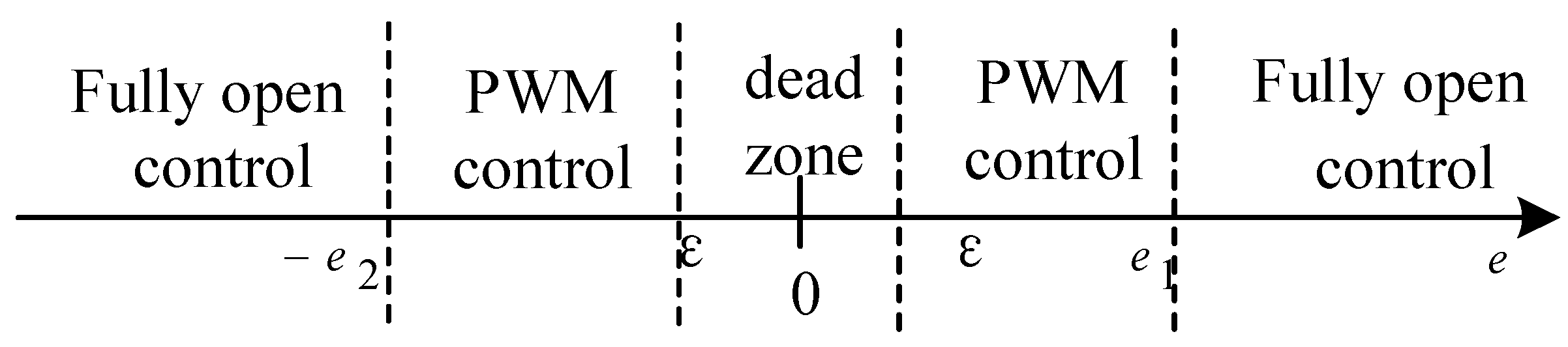
3. Five-Step Switch Control Strategy
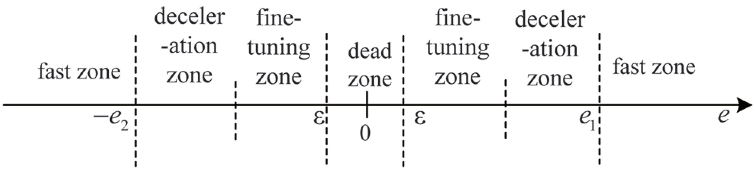
The traditional five-step switch control strategy is based on the combination of fully open control and PWM control, as shown in Figure 5. e represents the valve position error value, which is the difference between the valve position feedback value and the set value. is the valve position demarcation point in the intake stage. represents the valve position demarcation point in the exhaust stage. and were obtained based on past experience. is the dead-zone range, generally taken as 0.5% FSR, and FSR is expressed as the full scale range of the valve position. According to the size of e, the control process is divided into a fully open control zone, PWM control zone, and dead zone.

Figure 5.
Traditional five-step switch control algorithm.
The specific control process is as follows:
- (1)
- When or , the valve positioner is controlled via the fully open intake valve or fully open exhaust valve. This can quickly intake or exhaust, and quickly reduce the error.
- (2)
- When or , the valve positioner uses the PWM control method. It adopts a suitable period and duty cycle to output the PWM. In this way, the actuator can be adjusted in a small range, and the error value can be slowly reduced.
- (3)
- When , the piezoelectric valve of the valve positioner is in a static state.
The traditional five step control algorithm is not suitable for small valve position changes, and the switching point of each part does not give a very clear means of implementation. For the different types of control valves with different processes, the friction and pneumatic structure are quite different. The dead zone, maximum speed at which oscillation can occur, initial PWM, and PWM for maintaining smooth movement are also quite different. This makes it difficult for the above strategies to achieve high-precision and stable control. It is necessary to adjust and identify the model parameters and select different control parameters for different control stages.
4. A Positioning Strategy Combining Parameter Tuning and Optimal Control
4.1. Self-Tuning of Pneumatic Control Valve Parameters
To overcome the shortcomings of the five-step switch control strategy, this paper proposes a strategy to identify the characteristic parameters of the intelligent positioner. Figure 6 shows the identification process of the characteristic parameters of the control valve with a sampling frequency of 100 Hz. It can automatically identify the following parameters of the piezoelectric pneumatic actuator:

Figure 6.
Identification process of parameter self-tuning.
- Pneumatic control valve, stroke type;
- Minimal start pwm for pneumatic control valve;
- Maximum speed of the pneumatic control valve and its overshoot;
- Reference speed and reference speed pwm for the pneumatic control valve.
Through this identification method, the generality of most control algorithms under the action of single-acting and double-acting cylinders is guaranteed.
4.1.1. Pneumatic Control Valve—Stroke Type
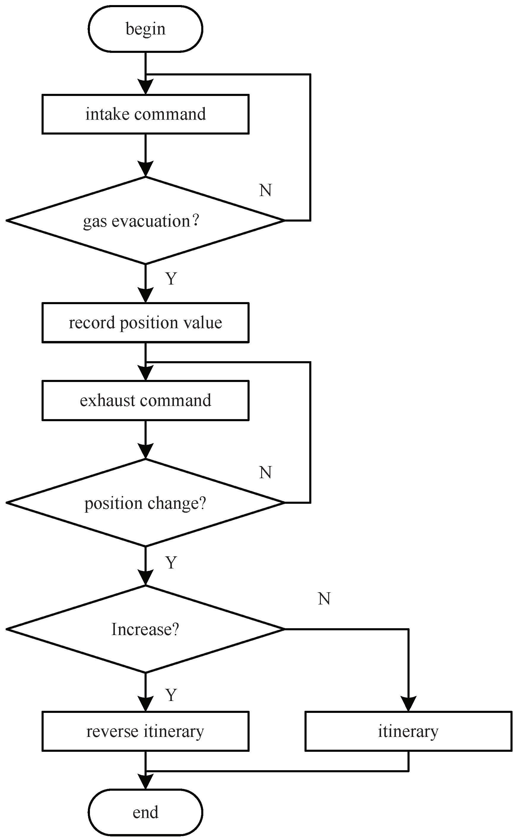
The control valve cylinders are divided into single-acting and double-acting. The single-acting pneumatic membrane control valves can be divided into air-opening and air-closing according to the action direction structure. The air inlet of the air-opening control valve is at the lower end of the cylinder. When it is inflated, the spring will be compressed to push the valve stem upward, thereby increasing the opening of the control valve. The air inlet of the air-to-close control valve is at the upper end of the cylinder. When inflated, the spring will compress the spring to push the valve stem downward, thereby reducing the opening of the control valve, as shown in Figure 7. Firstly, the piezoelectric valve is in the fully open exhaust valve state until the gas in the cylinder of the control valve is drained, and the current valve position is recorded as the initial valve position. Then, make the piezoelectric valve fully open to judge whether the valve position increases. If it increases, the control valve is in reverse itinerary state, and vice versa.

Figure 7.
Flowchart of stroke type identification.
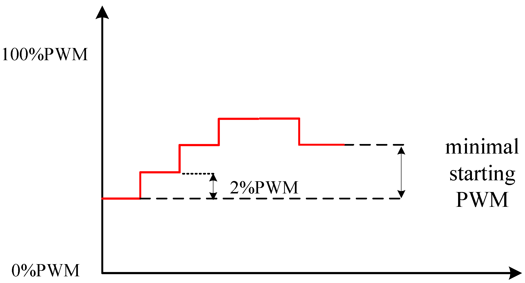
4.1.2. Minimal Start PWM for Pneumatic Control Valve
If there is high friction in the system, the valve position will start too slowly. As shown in Figure 8, curve A is that the stem is subject to 200 N friction, and curve B is when it is subject to 100 N friction. When the same PWM is used to inflate, the stable time for curve A to reach the target position is obviously longer than the time for curve B. To meet the performance index, the minimal starting PWM of the control valve should be set in the characteristic parameter tuning stage to reduce the influence of friction on the valve stem.
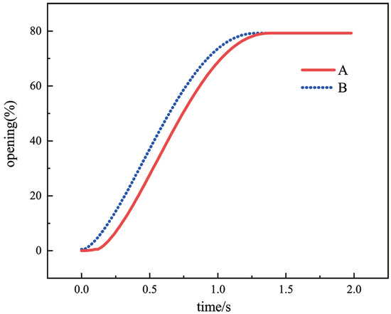
Figure 8.
Valve position response under different frictional forces.
Check whether an amplifier is installed at the intake port of the piezoelectric valve. The amplifier can speed up the intake rate of the piezoelectric valve. For control valves with amplifiers or double-acting cylinders, there is no need to set the minimum start PWM and record it as 0, because in this case a relatively small PWM will make the valve position move quickly. Otherwise, for the control valve of a single-acting cylinder, the minimum start PWM identification process is shown in Figure 9. The valve position starts to move from one end, and the PWM is increased by 2% until the valve position starts to move, and the current PWM is recorded. To avoid too slow a start of the valve position, increase the current PWM by 4% and record it as the minimal start PWM.

Figure 9.
Minimum start PWM identification process.
4.1.3. Maximum Speed of Pneumatic Control Valve and Its Overshoot
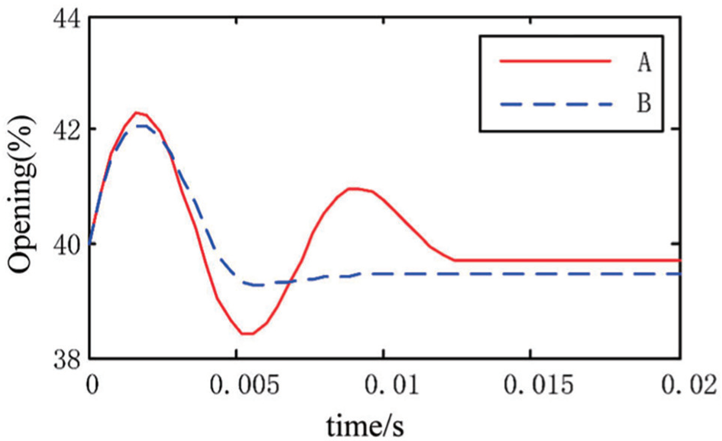
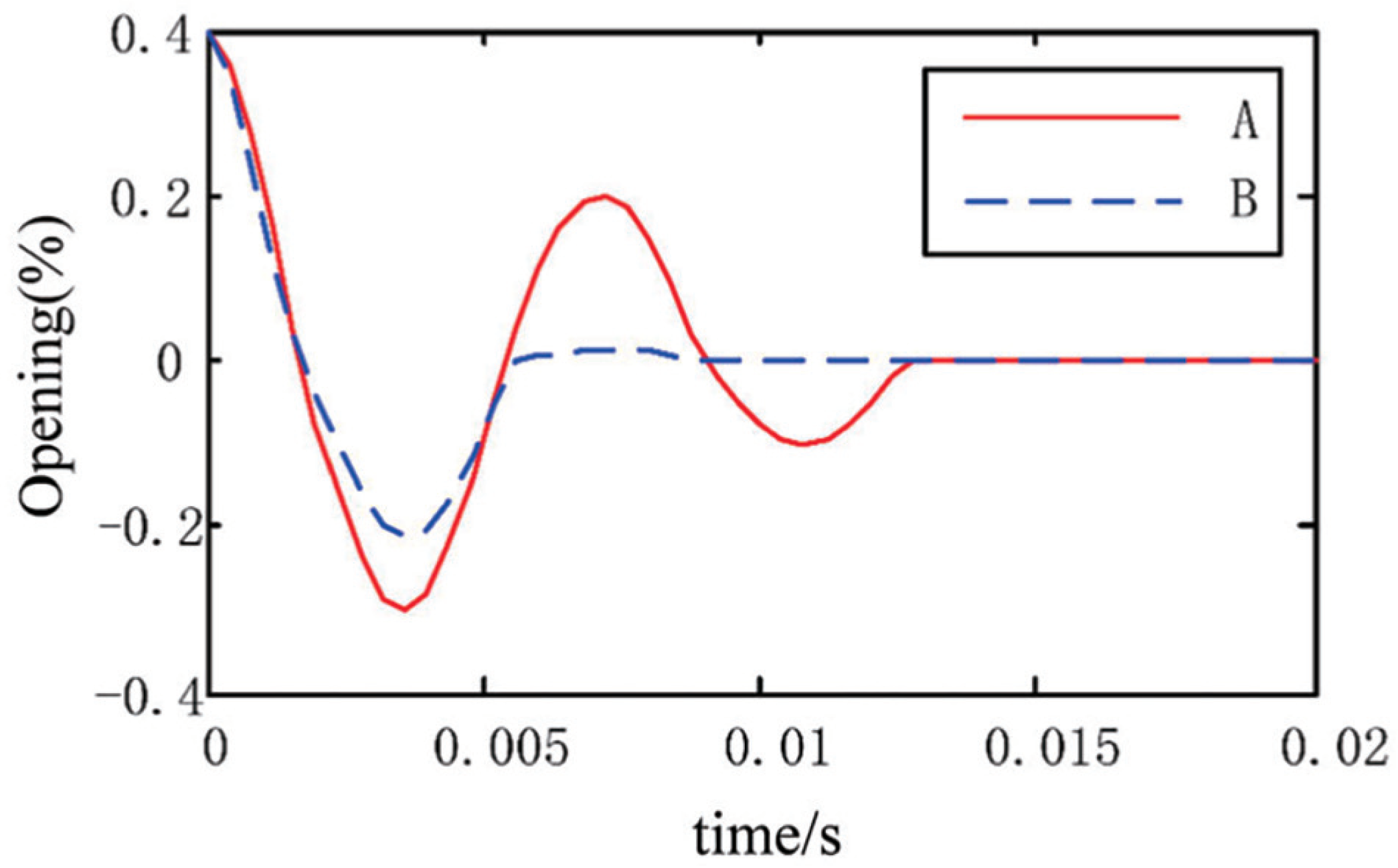
In the five-step switching algorithm, fully open control is used when the valve position error is relatively large, and PWM control is used when the valve position error is relatively small. The fully open control and PWM control switching point are extra important for the five-step switching algorithm. If the switching point is close to the dead zone, the fully open control range is too large. As shown in Figure 10, curve A is a situation where the switching point is set close, and curve B is a situation where the switching point is set appropriately. Curve A has been overshooting. If the switching point is set far away from the dead zone, the PWM control range is too large, which will easily lead to an overly long valve position positioning time.
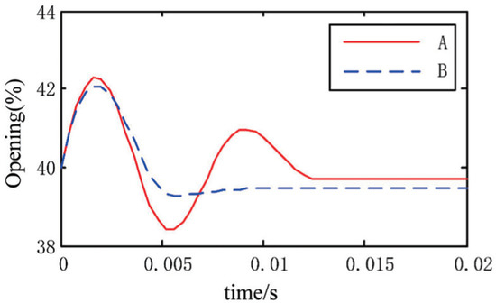
Figure 10.
Valve position responses of different switching points.
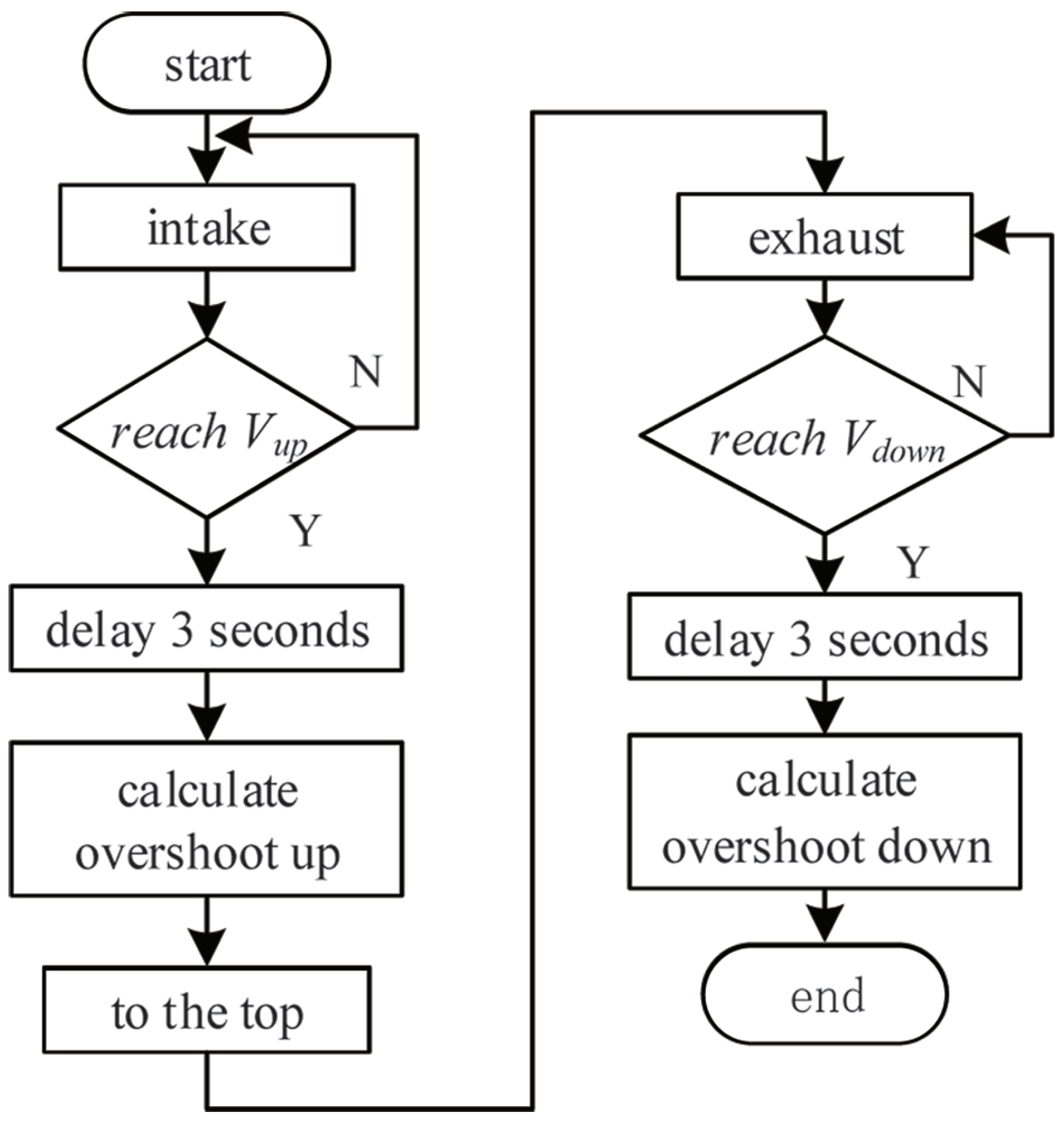
Within the full scale range of the control valve, determine the speed value, , of the current valve position through the valve position values of n consecutive control cycles in the past; is the value position at the previous moment.
As shown in Figure 11, the maximal valve position rising speed and the maximal valve position decreasing speed are detected. When the valve position reaches the maximal speed, the current valve position is recorded as ; the piezoelectric valve sends a hold command. Then, it delays three seconds and the current valve position is recorded as . The overshoot in the rising process is and in the falling process is . The overshoot is calculated.
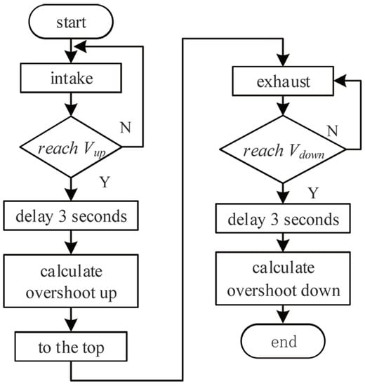
Figure 11.
Self-identification flowchart for maximum speed and overshoot.
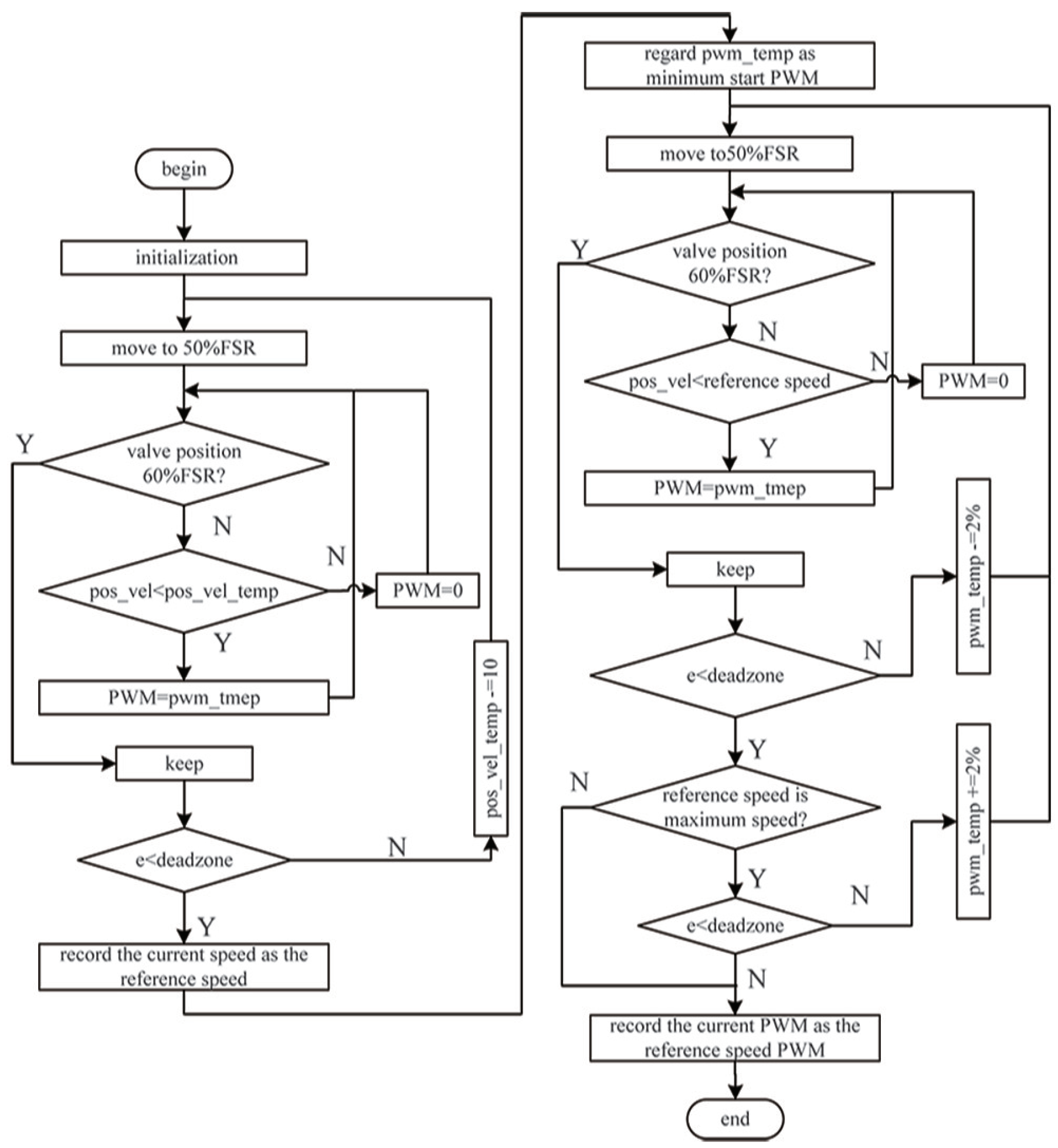
4.1.4. Reference Speed and Reference Speed PWM for Pneumatic Control Valve
The overshoots identified in the previous step were taken as switching points of the optimal control strategy. As shown in Figure 12, when the valve position is gradually approaching the dead zone within the range of the maximal overshoot, if the speed is too fast at this time, the valve position will overshoot. Curve A is the initial speed of the valve stem 0.8 m/s, and curve B is the initial speed of the valve stem 0.2 m/s. It is necessary to identify a reference speed of the valve position operation. The speed can reach the dead zone smoothly without causing overshoot of the valve position. It is also necessary to identify the PWM that maintains this speed.
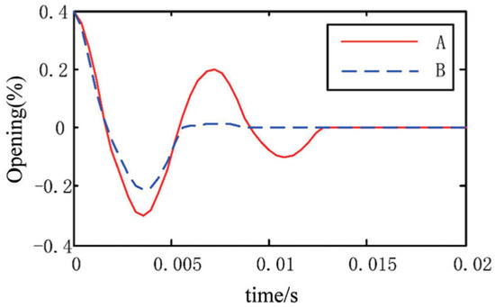
Figure 12.
Valve position response under different valve position speeds.
First, we identify the reference speed (see Figure 13). In the initialization phase, set the valve position safety speed to the maximum speed identified in the previous step, and set to the minimum start PWM. If the current valve position speed is less than , PWM is set to . Until the valve position is adjusted to 60% FSR, it is held for 5 s. Determine whether the absolute value of the target valve position and the actual valve position are less than the dead zone value. If valve position is in the dead zone, the current speed is recorded as the reference speed. Otherwise, subtracts 10, and we reposition the valve to 50% FSR.
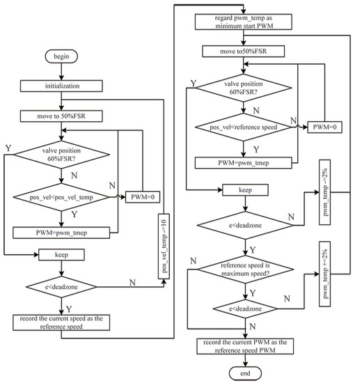
Figure 13.
Self-identification flowchart of the reference speed and reference PWM.
Second, we identify the reference speed PWM. We re-initialize the valve position. If the current valve position speed is less than the reference speed, PWM is set to x and held for 5 s until the valve position is adjusted to 60% FSR. We determine whether the absolute value of the target valve position and the actual valve position are less than the dead zone. If valve position is greater than the dead zone, decreases by 2%. Otherwise, we judge whether the reference speed is the maximum speed. If it is not the maximum speed, the current PWM is recorded as the reference PWM. If it is the maximum speed and the absolute values of the target valve position and the actual valve position are less than the dead zone value for two consecutive times, the current PWM is recorded as the reference PWM.
4.2. Optimal Control Strategy Based on Parameter Self-Tuning
The partition of the optimal control algorithm is shown in Figure 14. According to the error of valve position, the whole control process is re-divided into a fast zone, deceleration zone, fine-tuning zone, and dead zone. and are the identified maximal overshoot in the rising/decreasing process, and , and denotes the dead zone range.
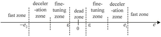
Figure 14.
Optimal control strategy of pneumatic control valve.
The optimal control strategy adopts fast start and slow end methods, when the valve position is in the fast zone, deceleration zone, fine-tuning zone, and dead zone, different control methods are used. The specific process of the control strategy is shown in Figure 15:
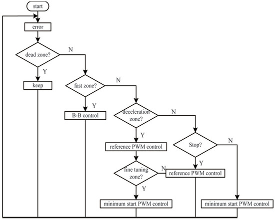
Figure 15.
The concrete realization of the optimal control strategy.
- When the valve position error is in the fast zone, the fully open control is adopted; it can quickly reduce the error. The fully open control can meet the adjustment time and avoid the influence of static friction of the valve stem during the transition from static to moving, as shown in Equation (24).
- When e is in the deceleration zone within the range of and , the reference speed PWM control is used, and the valve position speed is detected.
- When is less than the reference speed, the valve position enters the fine-tuning zone. It not only satisfies the constraint condition and , but also avoids the vibration of the valve position. With the minimum start PWM control, the PWM starts to decrease by 4%, and the lower limit is the minimum start PWM, which achieves the purpose of slowly entering the dead zone of the valve position.
- When the valve position enters the dead zone range, , keep the piezoelectric valve in steady state.
5. Experimental Analysis and Comparison
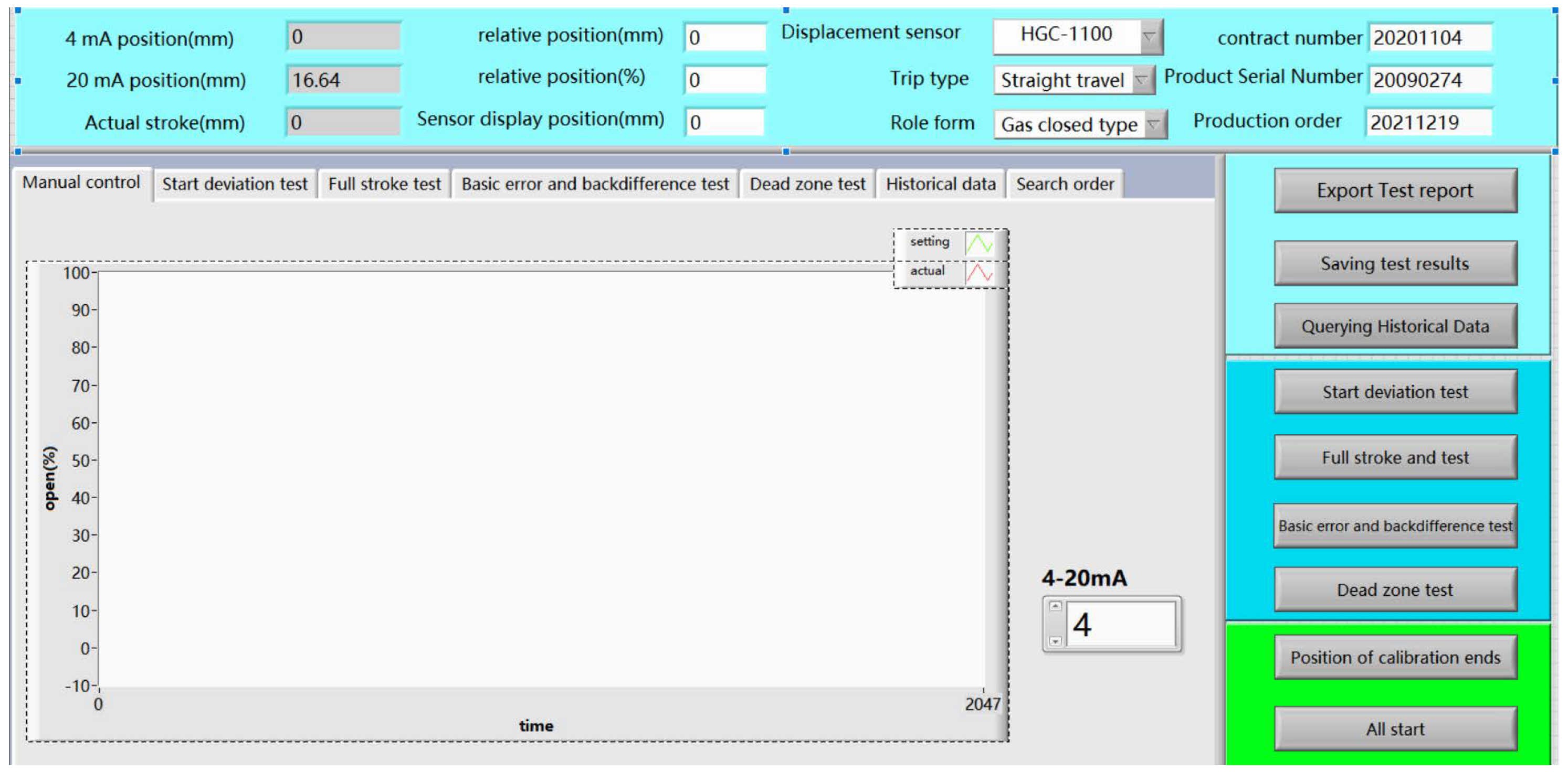
The intelligent pneumatic control valve uses 4–20 mA standard input current as the control signal. This experiment used the self-developed intelligent testing platform for performance testing, which can realize standard control, feedback acquisition, and intelligent calculation. The main interface of the control valve performance testing platform is shown in Figure 16.

Figure 16.
Control valve performance testing platform.
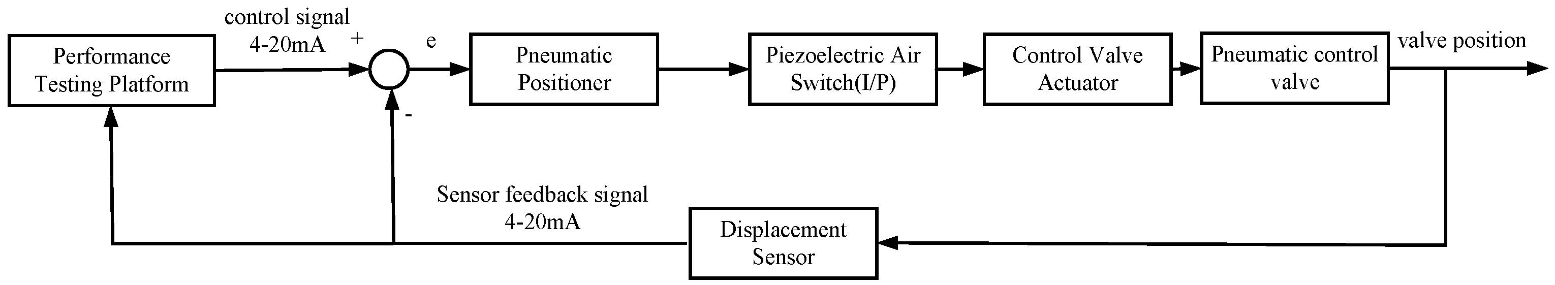
The 4–20 mA control signal is sent to positioner through the control valve performance testing platform to drive the valve position of the pneumatic control valve, and then the valve position signal is fed back to the testing platform through the displacement sensor. The detection platform receives the valve position feedback signal and performs calculations according to relevant national standards, and displays the signal in real time by displacement following the curve. The control system of the pneumatic control valve is shown in Figure 17.
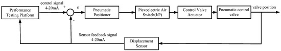
Figure 17.
Control system of the pneumatic control valve.
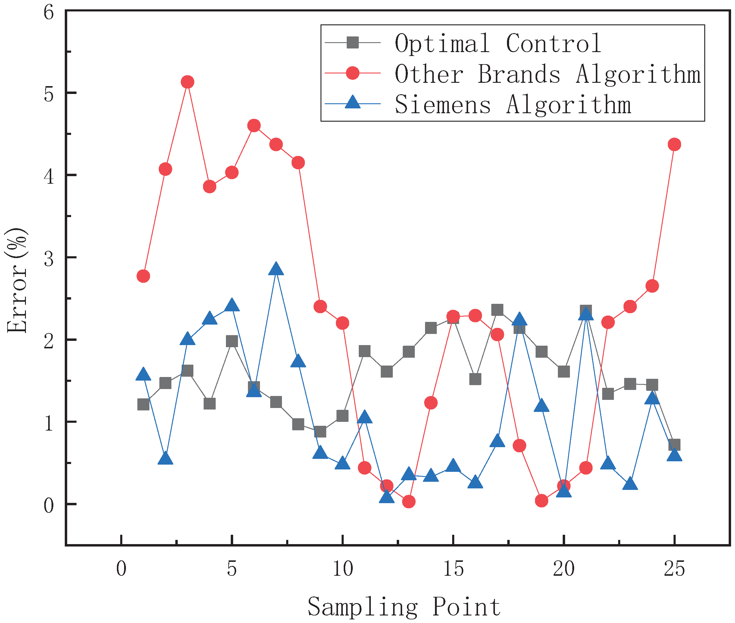
5.1. Small-Range Control Effect Comparison
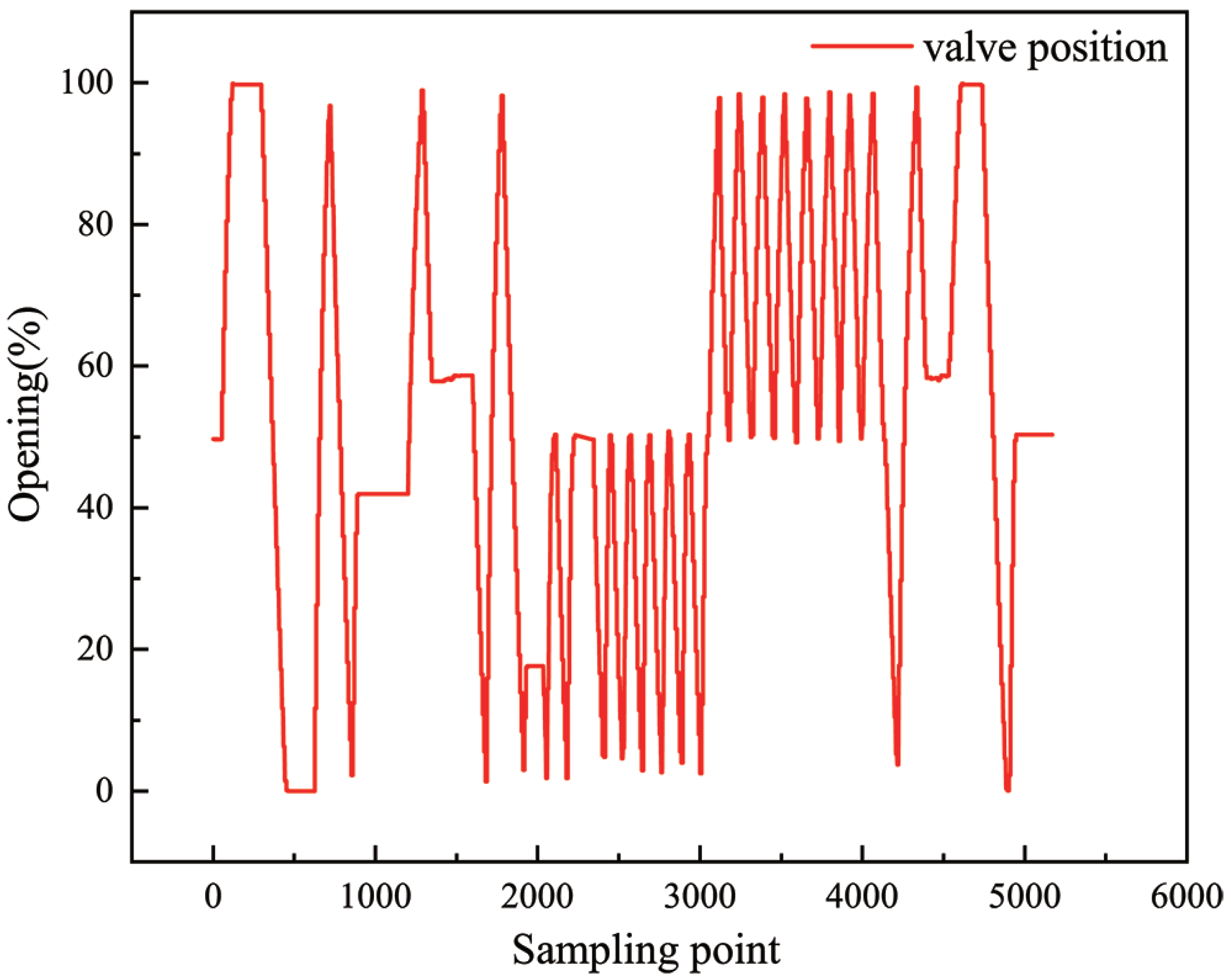
The control signal of intake or exhaust adopts a 1 mA-step signal. The small-range control algorithms comparison is shown in Figure 18. The sampling frequency is 5 Hz. Table 1 is a comparison of small-range intake control algorithms, and Table 2 is a comparison of small-range exhaust control algorithms. Compared with the control algorithms of other brands, the optimal control strategy proposed shortens the average intake adjustment time by 0.38 s, the average exhaust adjustment time by 1.18 s, the average adjustment time by 0.27 s, and the average error by 1.2%. Compared with the Siemens control algorithm, the average air intake adjustment time is shortened by 0.09 s, and the average adjustment time is reduced by 0.26 s. The error comparison results of each control algorithm are shown in Figure 19. It can be seen from the figure that the error accuracy of the algorithm proposed in this paper is better than those of other positioner algorithms.
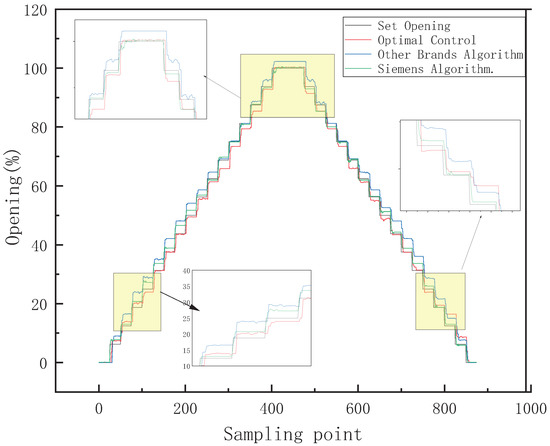
Figure 18.
Small-range control algorithms comparison.

Table 1.
Comparison of small-range intake control algorithms.
Table 2.
Comparison of small-range exhaust control algorithms.
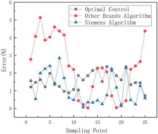
Figure 19.
Small-range control algorithms comparison.
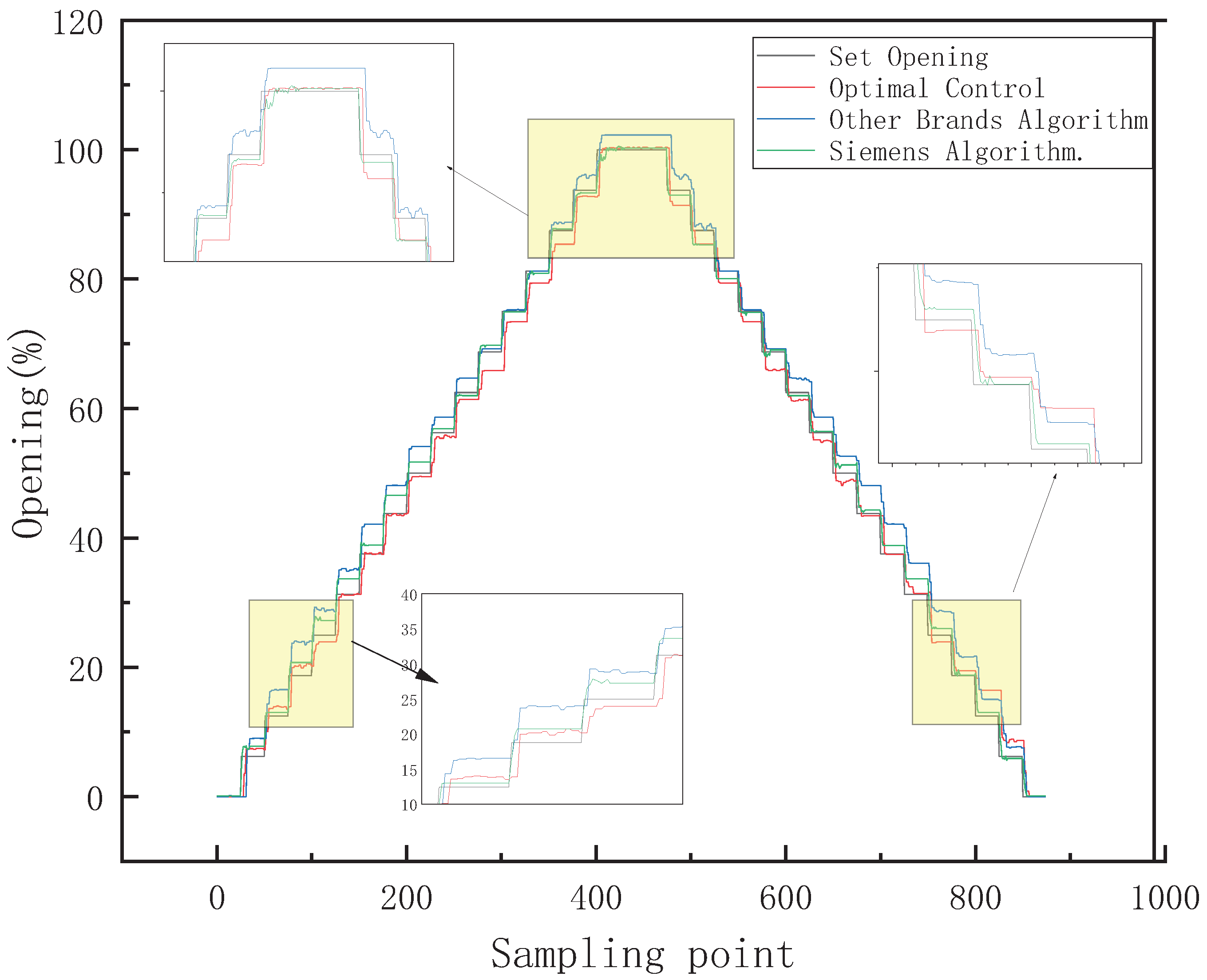
5.2. Large-Range Control Effect Comparison
The control signal of intake or exhaust adopts a 4 mA-step signal. The large-range control algorithms comparison is shown in Figure 20. The sampling frequency is 17 Hz. Table 3 is a comparison of large-range intake control algorithms, and Table 4 is a comparison of large-range exhaust control algorithms. Compared with other brand control algorithms, the optimal control strategy proposed in this paper shortens the average intake adjustment time by 1.09 s, the average exhaust adjustment time by 0.17 s, the average adjustment time by 0.63 s, and the average error by 0.48%. Compared with the Siemens control algorithm, the average intake adjustment time is shortened by 0.3 s, the average exhaust adjustment time is increased by 0.36 s, the average error is reduced by 0.21%, and the maximum error that occurs is much greater than 0.81%.
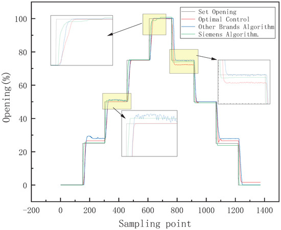
Figure 20.
Large-range control algorithms comparison.
Table 3.
Comparison of large-range intake control algorithms.
Table 4.
Comparison of large-range exhaust control algorithms.
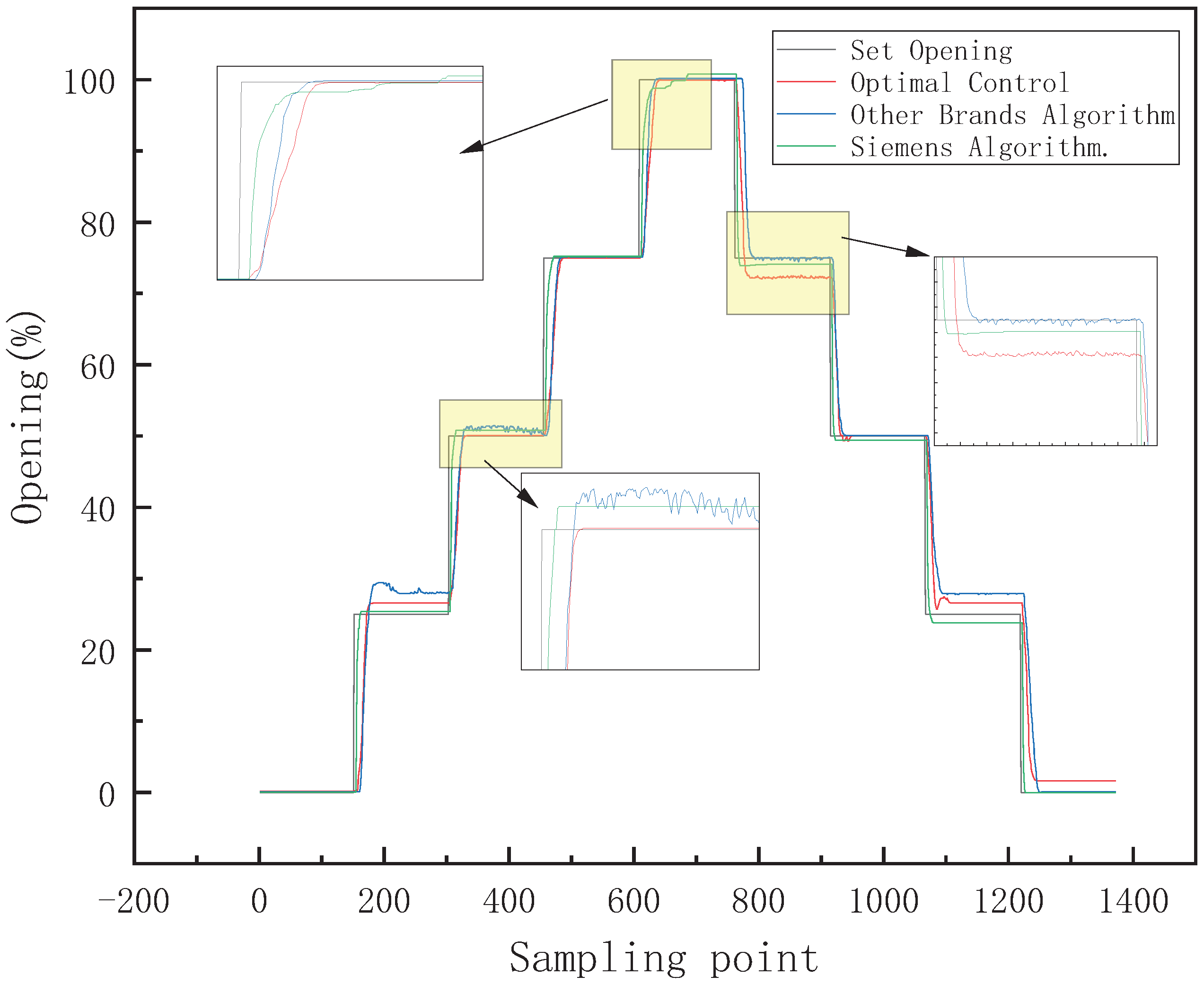
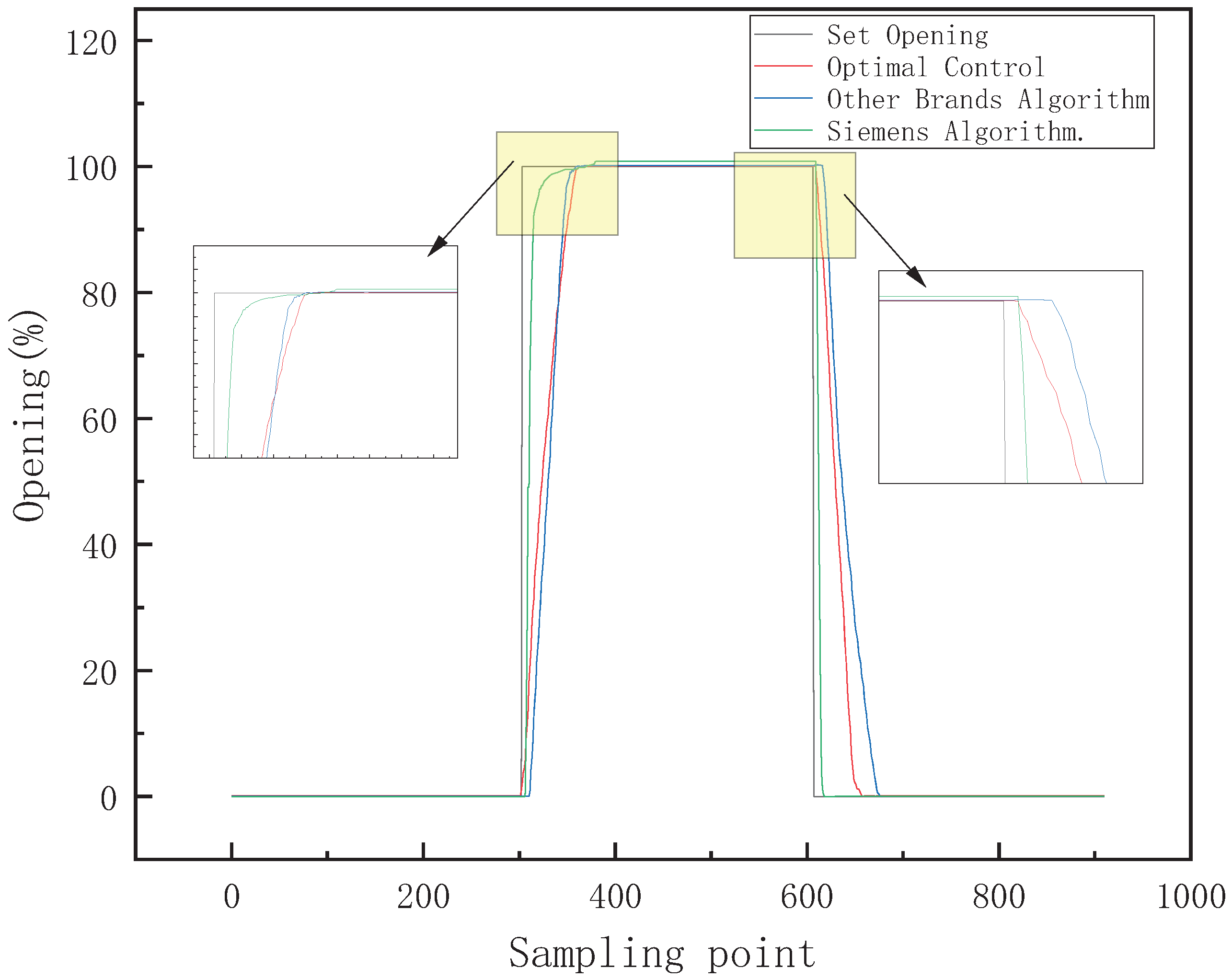
5.3. Full-Stroke Control Effect Comparison
The control signal of intake or exhaust adopts a 20 mA-step signal. The full-stroke control algorithms comparison is shown in Figure 21. The sampling frequency is 20 Hz. Table 5 is a comparison of full-stroke intake/exhaust control algorithms. Compared with Siemens control and other control algorithms, the optimal control strategy has improvements in adjustment time and average error.
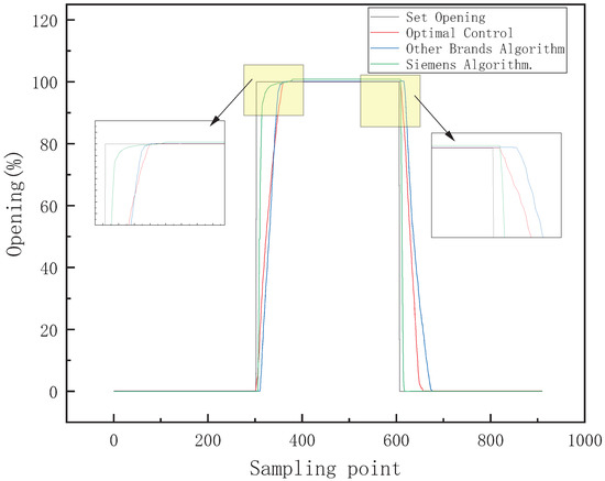
Figure 21.
Full-stroke control algorithms comparison.
Table 5.
Comparison of full-stroke intake/exhaust control algorithms.
6. Conclusions
The valve positioner is the core component of the pneumatic control valve, which plays a decisive role in the control precision and rapidity of the pneumatic control valve. Due to the large differences between different control valves, it is necessary to design a versatile strategy that can be applied to most positioner control algorithms. In this paper, a new position strategy of regulating the valve based on parameter tuning and optimal control by modeling and optimizing the pneumatic actuator is proposed. The identified parameters are applied to the improved control algorithm, which ensures the generality of most control algorithms under the action of single-acting and double-acting cylinder actuators. The experimental comparison and analysis were carried out on a specially developed platform to verify the performance of our proposed positioning strategy. The effects of various brand positioner control algorithms were measured through the intelligent positioner experiment platform. The results show that the effect of our positioning strategy is obviously superior to those of the common strategies, and all performance indicators were improved to some extent.
Author Contributions
Conceptualization, B.Z. and A.J.; methodology, B.Z. and A.J.; writing—review and editing, J.J. and B.Z.; software, J.J. and Y.Q.; funding acquisition, A.J.; data curation, Y.W. and L.X. All authors have read and agreed to the published version of the manuscript.
Funding
Zhejiang Provincial Natural Science Foundation, grant/award number: LY20F030010; The Key Research and Development Plan of Zhejiang Province of China, grant/award number: 2021C03034; National Natural Science Foundation of China, grant/award number: 61973102.
Institutional Review Board Statement
Not applicable.
Informed Consent Statement
Not applicable.
Data Availability Statement
The readers can access the data reported in this paper from the corresponding author.
Conflicts of Interest
The authors declare no conflict of interest.
References
- Gu, L.H.; Ge, X.Y.; Yao, X.D.; Jiang, B. Design of Intelligent Valve Positioner. Appl. Mech. Mater. 2013, 241, 552–556. [Google Scholar] [CrossRef]
- Mandali, A.; Dong, L. Modeling and Cascade Control of a Pneumatic Positioning System. J. Dyn. Syst. Meas. Control 2022, 144, 061004. [Google Scholar] [CrossRef]
- Cheng, Q.; Liu, Z.; Jiang, A.; Jiang, E.; Xiao, Y.; Li, F.; Jiang, J. Research on control algorithm of intelligent valve positioner based on parameter self-tuning. In Proceedings of the 2020 39th Chinese Control Conference (CCC), Shenyang, China, 27–29 July 2020; pp. 1380–1385. [Google Scholar]
- Jiang, E. Intelligent Control and Analysis of Piezoelectric Switch Valve Positioner. Master’s Thesis, Hangzhou Dianzi University, Hangzhou, China, 2020. [Google Scholar]
- Wu, J. Research on Output Feedback H Control for Offshore Platforms. Master’s Thesis, China Jiliang University, Hangzhou, China, 2017. [Google Scholar]
- Wang, C. Design of Intelligent Valve Positioner Control System. Process. Autom. Instrum. 2020, 41, 77–79. [Google Scholar]
- Shi, G. Research on Intelligent Control Tactic in Smart Electro-Pneumatic Valve Positioner. Ph.D. Dissertation, Chongqing University, Chongqing, China, 2011. [Google Scholar]
- Yan, B. Developing Trend and Product Planning of Intelligent Valve Positioner Technology. Instrum. Cust. 2015, 22, 23–25. [Google Scholar]
- Wang, K. Research on Control Algorithm of Intelligent Electric Valve Positioner. Master’s Thesis, Zhejiang University of Technology, Hangzhou, China, 2018. [Google Scholar]
- Fei, L.; You, J.F.; Hua, T.Z. The Research of a Piezoelectric Valve Positioner Control Algorithm. Adv. Mater. Res. 2014, 1030, 1565–1569. [Google Scholar]
- Lv, Y. Research on Nonlinear Characteristics and Algorithm of Intelligent Valve Positioner. Master’s Thesis, Zhejiang University of Technology, Hangzhou, China, 2020. [Google Scholar]
- Casas, J.; Quetsch, J.M. Radiation Hardness of the Siemens SIPART intelligent valve positioner. In Proceedings of the IOP Conference Series: Materials Science and Engineering, Kazimierz Dolny, Poland, 21–23 November 2019; p. 012196. [Google Scholar]
- McCormick, J.; Hagen, S. Leveraging Smart Valve Positioners. Chem. Eng. Prog. 2017, 113, 48–51. [Google Scholar]
- Papadopoulos, K.G.; Margaris, N.I. Optimal automatic tuning of active damping PID regulators. J. Process. Control 2013, 23, 905–915. [Google Scholar] [CrossRef]
- Hidalgo, M.C.; Garcia, C.; Angélico, B.A.; Tannuri, E.A. Embedded sliding mode controller applied to control valves with high friction. J. Control. Autom. Electr. Syst. 2019, 30, 677–687. [Google Scholar] [CrossRef]
- Li, X.; Chen, S.-L.; Teo, C.S.; Tan, K.K.; Lee, T.H. Data-driven modeling of control valve stiction using revised binary-tree structure. Ind. Eng. Chem. Res. 2015, 54, 330–337. [Google Scholar] [CrossRef]
- Khadim, Q.; Kiani-Oshtorjani, M.; Jaiswal, S.; Matikainen, M.K.; Mikkola, A. Estimating the Characteristic Curve of a Directional Control Valve in a Combined Multibody and Hydraulic System Using an Augmented Discrete Extended Kalman Filter. Sensors 2021, 21, 5029. [Google Scholar] [CrossRef]
- Muftah, M.N.; Faudzi, A.A.M.; Sahlan, S. Modeling and fuzzy FOPID controller tuned by PSO for pneumatic positioning system. Energies 2022, 15, 3757. [Google Scholar] [CrossRef]
- Xavier, M.S.; Fleming, A.J.; Yong, Y.K. Nonlinear Estimation and Control of Bending Soft Pneumatic Actuators Using Feedback Linearization and UKF. IEEE/ASME Trans. Mechatron. 2022, 27, 1919–1927. [Google Scholar] [CrossRef]
- Agh, S.M.; Pirkandi, J.; Mahmoodi, M.; Jahromi, M. Development of a novel rotary flow control valve with an electronic actuator and a pressure compensator valve for a gas turbine engine fuel control system. Flow Meas. Instrum. 2020, 74, 101759. [Google Scholar] [CrossRef]
- Chen, H.; Chang, S.; Fan, A. Model-based control of electromagnetic valve actuators for engine speed control. Int. J. Automot. Technol. 2019, 20, 127–135. [Google Scholar] [CrossRef]
- Liang, K.; Zhang, Y.; Jiang, X.; Chen, Z. Apery Integral Rule Self-study Fuzzy Control Arithmetic of Intelligent Valve Localizer. China Instrum. 2004, 8, 4–6. [Google Scholar]
- Jin, X. Research on Self-Tuning Algorithm of Intelligent Valve Positioner. Master’s Thesis, Zhejiang University, Hangzhou, China, 2013. [Google Scholar]
- Ma, Z.; Hu, E.; Mao, L.; Zhu, Z.; Liu, R. Design of Valve Positioner Based on Adaptive Fuzzy Immune PID. Comput. Meas. Control 2021, 29, 6. [Google Scholar]
- Yang, Q.; Xu, K.; Ren, B. Control method of piezoelectric valve positioner with variable PWM duty cycle. J. Electron. Meas. Instrum. 2014, 28, 424–433. [Google Scholar]
- Zhong, S.; Liu, Y. Piezoelectric valve type I/P conversion unit in intelligent valve positioner. Autom. Instrum. 2002, 79, 44–46. [Google Scholar]
- Liu, G.; Liao, X.; Hu, R. Control Algorithm Improvement for Intelligent Valve Positioner. Control Instrum. Chem. Ind. 2012, 39, 515–517. [Google Scholar]
- Wang, Q.; Xu, K.; Jiang, P. Parameter optimization self-tuning method of piezoelectric valve positioner. J. Electron. Meas. Instrum. 2011, 25, 612–619. [Google Scholar] [CrossRef]
- Liu, J.; Feng, Y.; Wang, J. Research on the Algorithm of Valve Position Adaptive Control for Intelligent Electro-pneumatic Valve Positioner. Instrum. Tech. Sens. 2012, 12, 151–152+155. [Google Scholar]
- Li, Y.; Zhang, L.; Siqin, P. Control Algorithm esearch of Hydraulic AGC System Based on High-speed On-off Valve. Mach. Tool Hydraul. 2016, 44, 135–139. [Google Scholar]


Publisher’s Note: MDPI stays neutral with regard to jurisdictional claims in published maps and institutional affiliations. |
© 2022 by the authors. Licensee MDPI, Basel, Switzerland. This article is an open access article distributed under the terms and conditions of the Creative Commons Attribution (CC BY) license (https://creativecommons.org/licenses/by/4.0/).