Article

Design, Micro-Fabrication, and Characterization of a 3-DoF Micro-Conveyor Based on Digital Actuators

1
College of Mechanical and Electrical Engineering, Xi’an Polytechnic University, Xi’an 710048, China
2
Xi’an Key Laboratory of Modern Intelligent Textile Equipment, Xi’an 710048, China
*
Author to whom correspondence should be addressed.
Actuators 2022, 11(10), 294; https://doi.org/10.3390/act11100294
Submission received: 29 August 2022 / Revised: 27 September 2022 / Accepted: 11 October 2022 / Published: 13 October 2022
(This article belongs to the Section Precision Actuators)

Abstract

:
In this paper, a novel optimal 3-DoF micro-conveyor based on electromagnetic digital actuators array is proposed. The micro-conveyor consists of four electromagnetic digital actuators. Two specific control strategies have been built to realize the 3-DoF planner conveyance task. A static analytical model and a dynamic semi-analytical model based on the principle have been built for the optimal design, analysis, and necessary calculation of a prototype. The prototype was manufactured by micro-fabrication technology and several experiments were carried out. The experimental results are in good agreement with the modeling results. Benefited from the optimal design and high fabrication precision, the proposed micro-conveyor is proved to be better in magnetic homogeneity of elementary actuators, output stability, long range conveyance linearity, and have one more DoF (planar rotation) compared to the previous work.

1. Introduction

In recent years, micro-conveyor dominates an increasingly important role in the field of precision engineering, such as micro-manipulation in biology [1,2], optical alignment [3,4], chip lithography and packaging in semiconductor manufacturing [5], and precision component position in micro-factory [6,7]. Due to the advantages of simple structure, open-loop control, small Joule heat effect, and low cost, digital actuators have become the alternative candidate to the design of micro-conveyors in order to meet several requirements such as miniaturization, high integration, simple control, and low energy consumption.
In literature, digital actuators have been used to design micro-conveyors and can be mainly classified into four categories according to their physical switching principles: electrostatic actuators [8,9], pneumatic actuators [10,11], piezoelectric actuators [5,12], and electromagnetic actuators [13,14,15]. Micro-conveyors based on electrostatic actuators have high efficiency and favorable scalability advantages [16], but they are vulnerable to environment (e.g., dust and moisture) and need to be encapsulated in package. Moreover, the motion range is limited by its initial air gap due to pull-in instability [17]. Micro-conveyors based on pneumatic actuators are fast in switching speed, but they require extra energy input to keep the conveyed object suspended in the working area thus high energy consumption is unavoidable during its operation [18,19]. In addition, the key components of their structure (multi-branch air nozzles and pipes) are also quite difficult to be integrated. Micro-conveyor based on piezoelectric actuators can realize sub-micron positioning precision and have high energy conversion. However, high voltage signal is needed for actuation and the existence of “backward motion” influences the continuity of output displacement [20,21]. Micro-conveyor based on electromagnetic actuators have quite large output stroke and output force which are their significant advantage compared with the other switching principles [22,23]. Moreover, they are relatively easy to be built and assembled in micro devices.
In our previous study [24], a prototype micro-conveyor based on eight elementary digital electromagnetic actuators was designed and fabricated in Université de Technologie de Compiègne (UTC) via conventional fabrication method. Based on stick-slip driving principle, a driving strategy was proposed and has been verified to achieve the micro-conveyor planar conveyance (2-DoF) application. However, three problems are worth noting, the first one is that the magnetic homogeneity of the previous device design was not enough which had influenced the static and dynamic behavior of the previous device. The second one is that the modeling of such systems is complex and time consuming as several physical phenomena (micro-collision, mass center shift, micro-vibration) which may influence the conveyor dynamic output performance should be considered simultaneously. The third one is that the output stability of the prototype micro-conveyor was found to be highly dependent on the elementary digital actuator manufacturing errors.
In order to solve these three problems and further validate the design principle. In this paper, a novel micro-conveyor with four optimized elementary digital electromagnetic actuators was designed and fabricated via micro-fabrication technology. A new driving strategy is introduced, which helps to achieve the third DoF (Planar rotation) of the micro-conveyor. Moreover, a novel semi-analytical dynamic model with high efficiency was created for the modeling of the micro-conveyor. Several experiments were carried out to test the dynamic performance of the novel prototype conveyor. Improvements of static (e.g., magnetic forces homogeneity, manufacturing errors) and dynamic performance (conveyance ability) were found in the novel prototype conveyor when compared to the prototype in the previous study.
The rest of this paper is organized as follows. In Section 2, the principle of the micro-conveyor is introduced. In Section 3, a static analytical model and a dynamic semi-analytical model based on the principle are built for the design, analysis, and necessary calculation of the prototype conveyor. In Section 4, the experimental setups are presented, and measurements of the prototype conveyor are carried out. Several experiments are conducted to validate the proposed design and test the performance of the prototype conveyor. The experimental results are also presented and discussed. Finally, Section 5 concludes the paper and future research is prospected.

2. Principle

2.1. Principle of the Elementary Electromagnetic Digital Actuator

The elementary electromagnetic digital actuator consists of a mobile part and a fixed part illustrated in Figure 1a,b. The mobile part of the elementary actuator is one movable permanent magnet (MPM) placed in a square cavity made of silicon. The fixed part consists of four fixed permanent magnets (FPMs) assembled around the square cavity and two orthogonal wires (x- and y-axis switching wires (XW, YW)) placed below the square cavity. The two switching wires were printed on a double side printed PCB. A thin glass layer has been used and placed between the MPM and the PCB to avoid electrical contact between the MPM and the PCB. It also ensures a flat surface on which the MPM moves. The elementary electromagnetic digital actuator dimensions and properties have been given in Table 1.
The MPM can be switched between four corners of the square cavity. When a current passes through a switching wire surrounded by the magnetic flux density from the MPM, Lorentz force is generated between the MPM and the switching wire. The MPM is then switched from one corner to another. The thickness of the PCB has been designed as thin as possible to reduce the difference of the generated Lorentz forces from the XW and YW with equivalent current. When no current is applied to the switching wires, the MPM will be held in one of the square cavity corners. The four FPMs around will generate a static magnetic force on the MPM along the two orthogonal axes (x- and y-axis). This force ensures the holding of the MPM in each corner of the square cavity without external energy supply. The four corners (Figure 1a 1,2,3,4) of the square cavity are also called stable positions of the elementary actuator.

2.2. Principle of the Micro-Conveyor

In the previous study, a micro-conveyance device based on eight elementary digital actuators have been designed and fabricated by conventional manufacturing method (in UTC) to realize linear conveyance. However, extra PMs were not added which resulted in inhomogeneous magnetic flux density around each elementary digital actuator. Therefore, the static magnetic forces exerted on each elementary actuator by the FPMs were inhomogeneous.
In this paper, the micro-conveyor is redesigned (Figure 1c) with four elementary digital actuators which are in 2 × 2 array form. The dimension, magnetization of the elementary digital actuators and the distances between them are redesigned based on a MATLAB static analytic model (presented in Section 3). Eight additional balance permanent magnet (BPM) are also designed and placed around the actuators array to homogenize the magnetic flux density of each elementary actuator in comparison to the previous design. The dimensions and the properties of the present micro-conveyor design are given in Table 1. The comparison of the present design and the previous design have been presented in the following sections.
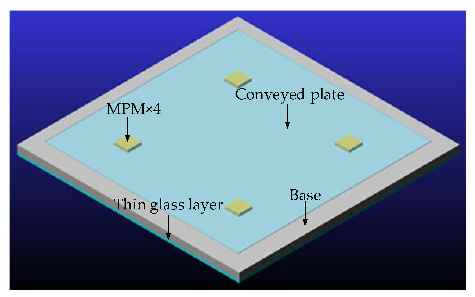
The stick-slip driving principle is employed to realize the conveyance application of the micro-conveyor. The conveyed object is a thin glass plate placed on the array which is just in contact with the 4 MPMs. According to the stick-slip principle, the conveyance of the conveyed plate can be divided into “slip” and “stick” process. During the “slip” process, the conveyed plate displaces due to the sufficient friction force between the MPMs and the conveyed plate. On the contrary, the conveyed plate is stationary due to the insufficient friction force during the “stick” process.
Two specific control strategies have been adopted to realize the “stick”/“slip” process as well as the 3-DoF conveyance application (linear conveyance and planar rotation) of the micro-conveyor. These two control strategies are called linear control strategy and rotation control strategy respectively which are explained in the following subsections.

2.2.1. Linear Conveyance (X-, Y-Axis Direction Movement)

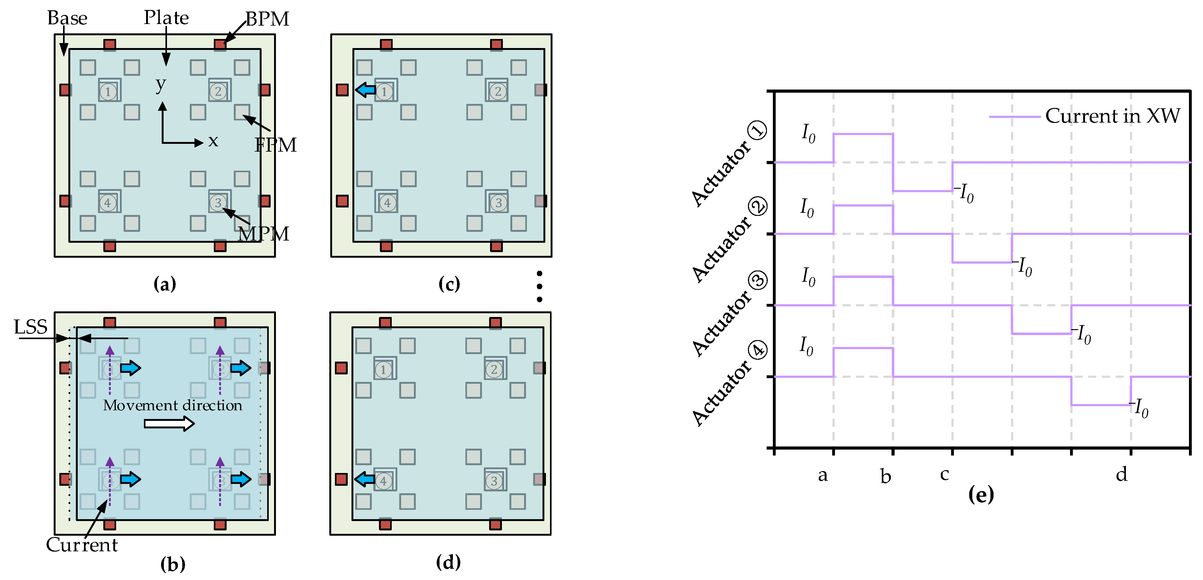
To realize the linear conveyance of the conveyed plate along x-/y-axis, linear control strategy has been used (illustrated in Figure 2).
The linear control strategy can be divided into: “slip” and “stick” process. As shown in Figure 2b, “slip” process is that all the MPMs are actuated from their same initial stable position to another same stable position simultaneously via control current. The conveyed plate is then actuated by the friction forces between the MPMs and the plate. The corresponding conveyed displacement of the plate is called linear step size (LSS). The “stick” process is that all the MPMs are actuated back to their initial stable position one after another (illustrated in Figure 2c,d) by reversing the control current, respectively. In the “stick” process, the conveyed plate is not moved due to the insufficient friction force theoretically. Based on this linear control strategy, the linear conveyance of the conveyed plate can be realized by repeating the “slip” to “stick” process along either x- or y-axis direction. Figure 2e presents the corresponding control signal (current pulse) for each elementary actuator in the whole driving sequence.

2.2.2. Planar Rotation (Z-Axis Rotation)

To realize the planar rotation of the conveyed plate in x-y plane (around z-axis), rotation control strategy has been used and shown in Figure 3.
The rotation control strategy can also be divided into: “slip” and “stick” process which are slightly different from the “slip” and “stick” process in the linear control strategy. Initial positions setup of all the MPMs (Figure 3a ①②③④) is needed before the planar actuation to finish the planar rotation. The “Slip” process is that all the MPMs are simultaneously actuated to different stable positions (illustrated in Figure 3b) via four independent control current. The actuation directions are different for the four elementary actuators. The conveyed plate is then actuated in the clockwise direction by the friction forces between the MPMs and the plate. The corresponding conveyed angle of the plate is called rotation step size (RSS). The “stick” process is that all the MPMs are actuated back to initial stable position one after another (illustrated in Figure 3c,d) by reversing the control current, respectively. Based on this rotation control strategy, the planar rotation of the conveyed plate can be realized by repeating the “slip” to “stick” process around the z-axis direction. Figure 3e presents the corresponding control signal (current pulse) for each elementary actuator in the whole driving sequence.

3. Modeling and Design Analysis

In this section, two models of the presented micro-conveyor have been carried out. The first model is about the necessary electromagnetic forces and static magnetic forces calculation between the MPMs and XW/YW, the MPMs and all the other PMs, respectively. This model is a static analytical model based on MATLAB software which helps to design and optimize the prototype. The second model is about the dynamic analysis of the presented micro-conveyor built with ADAMS software. It is a semi-analytical model which enables to provide a fast and precise dynamical simulation. The principles of the two models are presented below.

3.1. MATLAB Static Model

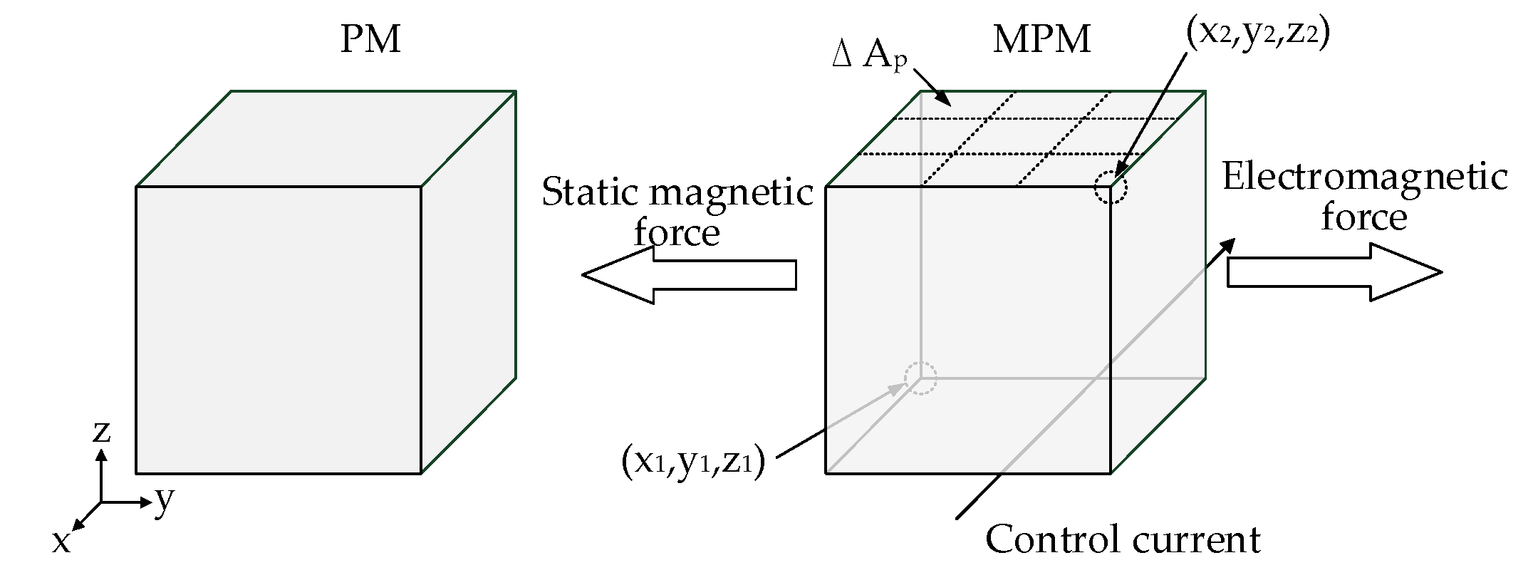
To calculate the static magnetic forces and the electromagnetic forces (illustrated in Figure 4) exerted each MPM in the micro-conveyor, magnetic charge model [25] has been used for the calculation of the PM magnetic flux density which can be expressed by Equation (1). Where μ0 is the magnetic permeability of air (4π × 107 N*A−2), M is the magnetization of the PM (A/m), (x2x1), (y2y1), (z2z1) are dimensions of the PMs, and (x, y, z) is coordinates of the computing point. In this model, the geometry of all the PMs is considered to be perfect, and the magnetization distribution is uniform along the z-axis. The magnetic flux density (Bx, By, Bz) generated by all PMs in the point (x, y, z) can be calculated by Equation (1).
B x ( x , y , z ) = μ 0 M 4 π k = 1 2 m = 1 2 ( 1 ) k + m × l n [ ( y y 1 ) + ( ( x x m ) 2 + ( y y 1 ) 2 + ( z z k ) 2 ) 1 / 2 ( y y 2 ) + ( ( x x m ) 2 + ( y y 2 ) 2 + ( z z k ) 2 ) 1 / 2 ]
B y ( x , y , z ) = μ 0 M 4 π k = 1 2 m = 1 2 ( 1 ) k + m × l n [ ( x x 1 ) + ( ( x x 1 ) 2 + ( y y m ) 2 + ( z z k ) 2 ) 1 / 2 ( x x 2 ) + ( ( x x 1 ) 2 + ( y y m ) 2 + ( z z k ) 2 ) 1 / 2 ]
B z ( x , y , z ) = μ 0 M 4 π k = 1 2 n = 1 2 m = 1 2 ( 1 ) k + n + m × t a n 1 [ ( x x n ) ( y y m ) ( z z k ) ( ( x x n ) 2 + ( y y m ) 2 + ( z z k ) 2 ) 1 / 2 ]            
Equation (2) is used to compute the static magnetic forces exerted on each MPM owing to the external magnetic flux density generated by the extra PMs, where, σm is the surface charge density of the considered MPM, Bext is the magnetic flux density on the pole surface of the considered MPM, ∆Ap is the area of the pole surface. The electromagnetic forces exerted on each MPM can be calculated via Equation (3), where I is the current value, and Bext is the magnetic flux density generated by the MPM. These three equations above have been implemented in MATLAB software. Moreover, the static magnetic force and electromagnetic force exerted on each MPM were calculated and presented in Figure 5 and Figure 6, respectively.
F m = p σ m ( x p ) B e x t ( x p ) Δ A p    
F e m = I w i r e   d l × B e x t
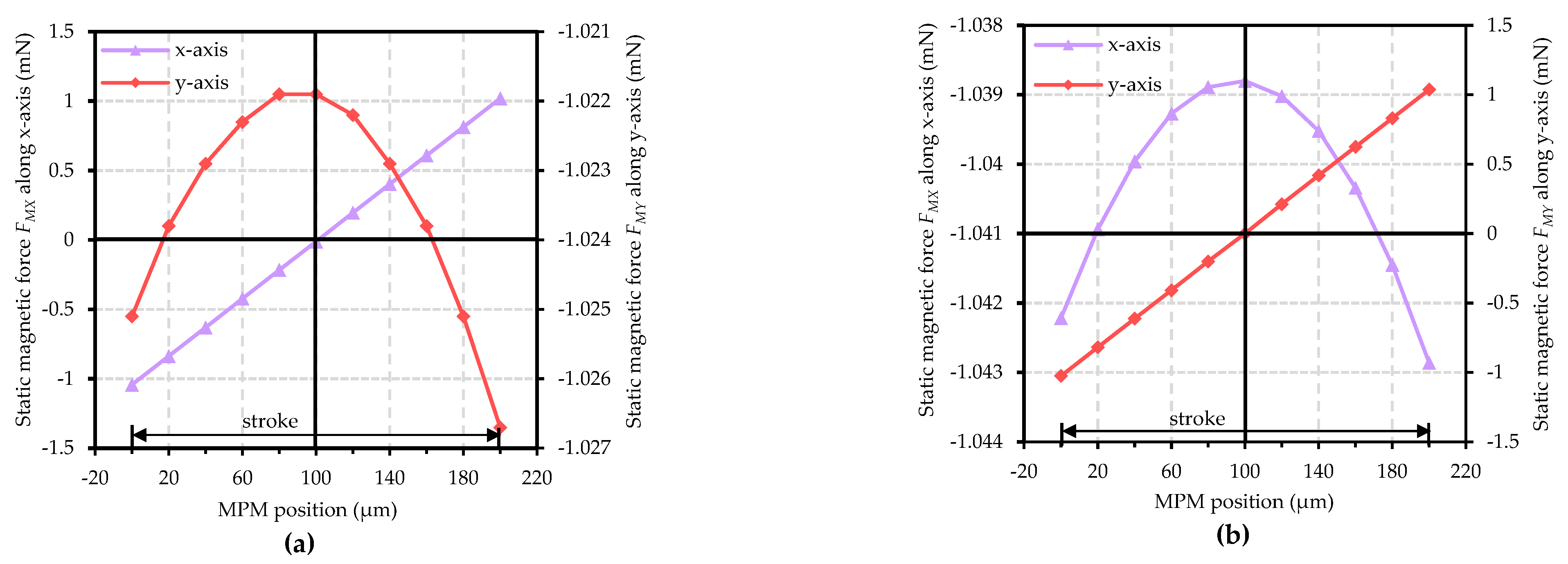
In the micro-conveyor, each MPM is subjected to two components of static magnetic forces (FMX, FMY) along the x- and y-axis direction, respectively. It can be observed in Figure 5a that the static magnetic force FMX value is symmetrical in the square cavity. This phenomenon is due to the symmetrical geometry design of the actuators array. The static magnetic force FMY value has a slight variation (maximum variation: 0.0048 mN), however, the variation is negligible as it is only 0.47% of the average static magnetic force FMY value. Similarly, the static magnetic force has the same characteristic along the y-axis direction (Figure 5b).
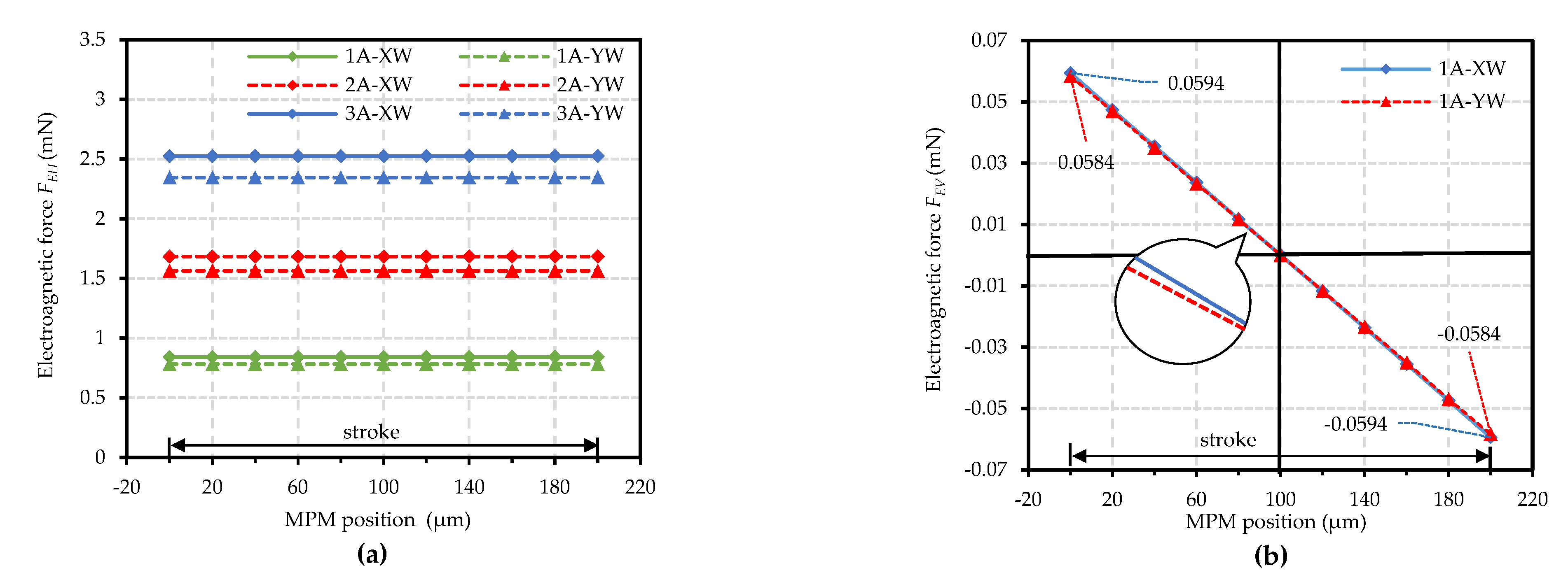
The electromagnetic forces exerted on each MPM with different switching current through the switching wires (XW, YW) are presented in Figure 6. The electromagnetic force has two components: the force along the horizontal direction (FEH), and the force along the vertical direction (FEV). It can be observed in Figure 6a that FEH is proportional to the switching current value (1A-XW/0.84 mN, 2A-XW/1.68 mN), and it remains constant within the stroke. However, the FEV varies with the MPM position change in the stroke (Figure 6b). This variation is due to the relative position change between the MPM and the switching wires below. Moreover, a difference between the electromagnetic forces generated by XW and YW for a certain switching current value can be observed. This difference is due to the distance between the XW and YW, the difference value is 0.06 mN at 1 A switching current (1A-XW/0.84 mN, 1A-YW/0.78 mN).
In the micro-conveyor, a homogeneous magnetic behavior of the elementary actuator is desired as the conveyance of the plate is realized based on an identical switching of each elementary actuator. The switching of each elementary actuator is determined by the static magnet forces and electromagnetic forces exerted on each elementary actuator under the same friction condition. In order to improve the elementary actuator homogeneous magnetic behavior of the previous work, the present micro-conveyor has been designed (including dimension and magnetization of the PMs, distances between the PMs, and distance between the switching wires and the MPMs) based on this MATLAB static model. A comparison about the static magnet and electromagnetic forces has been carried out between the previous and present design to determine the improvement of present design homogeneous magnetic behavior.
The static magnetic forces (exerted on each MPM) comparison between the previous and the present design are presented in Table 2. This comparison has been carried out in two aspects: First, the average static magnetic forces (in which MPMs are all placed in the same stable position) are compared. It can be observed that the present design average static magnetic force value is bigger than the value of the previous device. This increase in static magnetic force ensures a better holding of each MPM in the stable position than the previous design. A smaller standard deviation (±0.007 mN) of the average static magnetic force value can also be observed in the present design, which is just 0.68% of the average value. Second, the maximum variation of static magnetic forces at different stable positions (1,2,3,4) in the same square cavity are compared. A smaller maximum variation of static magnetic forces (0.009 mN) has been observed in the present design. Compared to the previous design, this maximum variation of static magnetic forces has been reduced by 92.7%. It is then indicated that the elementary actuators in the present design are subjected to more homogeneous static magnetic forces compared to the previous design. Thus, the present design is better in magnetic homogeneity.
The electromagnetic forces (exerted on each MPM) comparison between the previous and the present design are also presented in Table 2. It can be observed that the electromagnetic magnetic force of present design is a little bit smaller than that of the previous design. However, the difference between the electromagnetic magnetic forces generated by XW and YW of present design is smaller than that of the previous design due to the use of thinner PCB (100 μm) in the present design. The switching difference of elementary actuators in x- and y-axis can be decreased based on the presented design theoretically, which will be helpful to realize the rotation conveyance application.

3.2. ADAMS Dynamic Model

In this section, ADAMS software has been used for the dynamic modeling of the prototype design as this software has high-efficiency modeling function, fast analysis ability and flexible post-processing technology, which can effectively evaluate various dynamic performance of complex mechanical system.
The modeling of the prototype has been carried out in three steps. First, the micro-conveyor virtual prototype (Figure 7) has been built in ADAMS according to the component constraint relations (presented in Table 3), structural parameters, and material properties (presented in Table 1). The mass center of all the components is defined automatically by the software and the mass center shift phenomena is then considered during the simulation. The IMPACT function of ADAMS software is used to simulate the micro-collision phenomena (between the MPM and the base) and micro-vibration phenomena (between the MPM and the plate). The Coulomb friction is set between the MPMs and the square cavity, the conveyed plate, and the glass layer respectively. Second, the STEP function (time-varying force) in ADAMS software is used to simulate the electromagnetic forces generated by the XW/YW (Figure 6). In addition, the AKISPL function (displacement-varying force) is used to simulate the static magnetic forces generated by the FPMs (Figure 5). Third, the dynamic performance indicators (e.g., LSS, RSS, etc.) of the prototype can be achieved by operating the simulation with different control parameters (e.g., control current value, added mass value, etc.). The corresponding parameters set in ADAMS are presented in Table 3.
Thanks to the high-efficiency of the ADAMS software, the modeling of the micro-conveyor can be carried out within quite a short time. Moreover, the dynamic behavior of the micro-conveyor can be obtained easily without extra complex modeling of the microscopic phenomena (e.g., micro-collision, the conveyed plate mass center shift, micro-vibration) during switching. These mentioned microscopic phenomena have all been considered by an inner calculation of the components constraint (presented in Table 3) block of the ADAMS software. The modeling results have been presented in Section 4.

4. Experiments and Analysis

In this section, experimental setup is introduced, several experiments have been carried out to test the dynamic performance of the micro-conveyor, the experimental results have been compared and discussed with the ADAMS modeling results.

4.1. Experimental Setup

4.1.1. Description of the Prototype

In order to minimize the prototype manufacturing error, the base of the prototype (Figure 8) was fabricated via micro-fabrication technology. Non-magnetic material silicon was selected for the base structure to avoid affecting the global magnetic flux density. To fabricate the square cavities and mounting holes on the silicon prototype base, we targeted a 1.25 mm silicon depth using a mask for positive photoresist (AZ9260) which is suitable and can be deposited with a thickness of more than 10 μm. The photoresist was exposed to UV light in a mask aligner (EVG 620) and was developed in the developer (AZ400K). Inductive coupled plasma deep reactive ion etching (ICP-DRIE) technology [26] was used for etching the geometry pattern of the square cavities in the silicon base. Bosch process was applied by alternating the etching (material: sulfur hexafluoride (SF6)) and passivation (material: octafluorocyclobutane (C4F8)) steps. With the alternation of SF6 and C4F8, the vertical boundaries of the square cavities were obtained and the high precision of the elementary actuators was ensured.
An evaluation of the manufacturing errors on the silicon prototype base was carried out. The square cavities etched on the base were measured by an electron microscope (A0-V128S). The influence of the manufacturing errors is given in Table 4 with the help of the MATLAB model. In this table, the maximum and minimum influences of the manufacturing errors on the average static magnetic force (1.031 mN) have been determined by considering the maximum and minimum error values respectively. Compared to previous study where conventional fabrication was adopted, manufacturing error from the present micro-fabricated prototype is indeed decreased. Furthermore, the influence of manufacturing error on the static magnetic force is decreased as well.

4.1.2. Control System

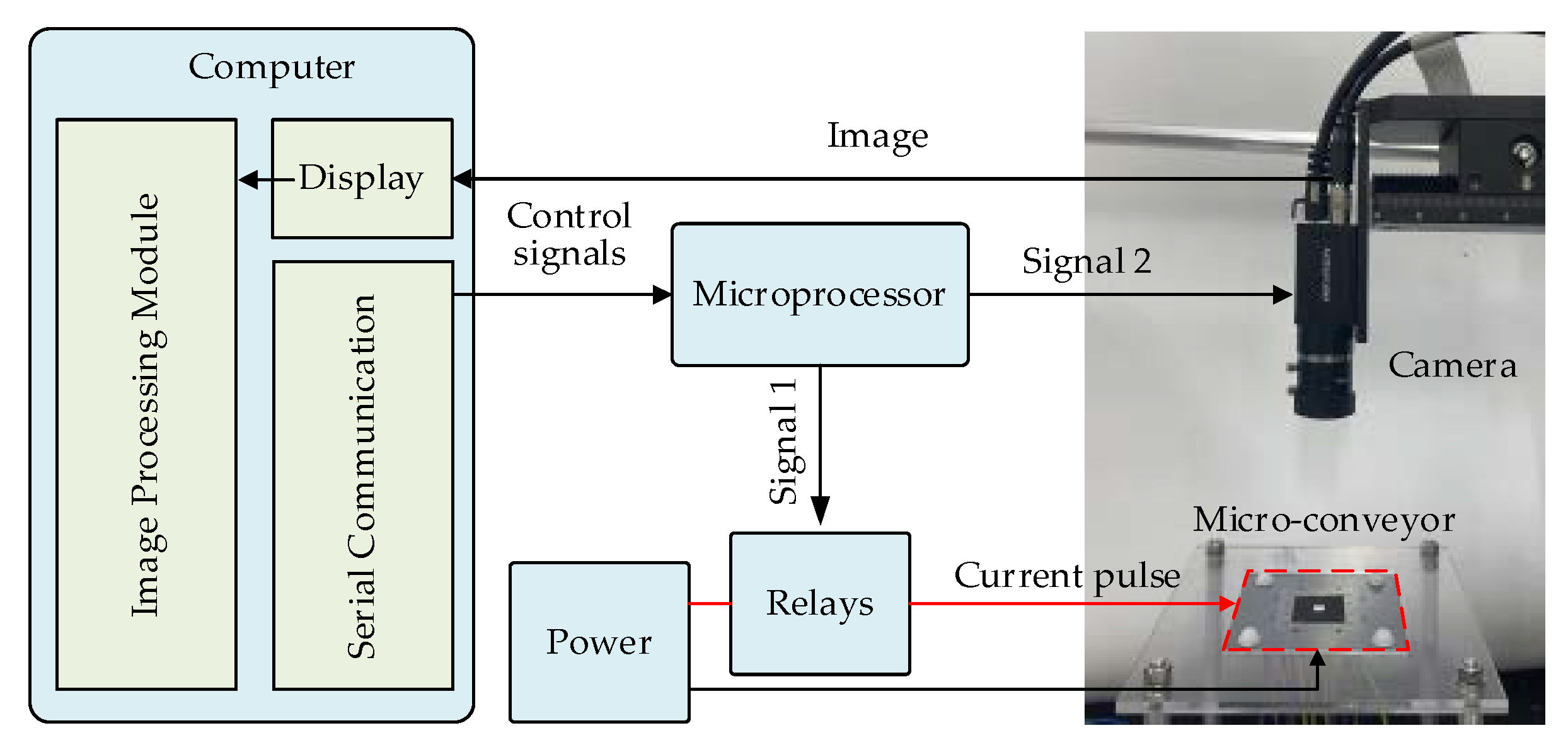
The control system for the prototype experimental test is schematized in Figure 9. It consists of a computer, a Microprocessor (MCS-89C52), two DC power supplies (KA3005D), a CCD industrial camera (MV-CA060), and 14 electromagnetic relays. A host computer program has been built which enables the computer to send control signals to the microprocessor through serial communication. The microprocessor is used to realize the conversion of a continuous DC electrical signal into a pulse signal by controlling the pull-in switch of electromagnetic relays. The CCD industrial camera can be controlled by the microprocessor to obtain the positioning information of the conveyed plate during its conveyance. Owing to the non-contact measuring technique, the positioning information of the conveyed plate can be post-processed in the computer and the LSS/RSS value can be achieved.
To accomplish the non-contact measuring of the conveyed plate, a square marker (Figure 10a) has been used and pasted on the top surface of the conveyed plate. An image processing program has been built which enables to detect the center of the mentioned square marker via the canny edge detection algorithm. The canny edge detection algorithm [27] has been carried out in three steps. First, the image is gray processed and the square maker edge is detected (Figure 10c). Second, the detected square maker edge is linear fitted to a calculated square edge (Figure 10d). Third, the center position of the square maker is calculated based on the calculated square edge (Figure 10d). Owing to the canny edge detection algorithm, the LSS/RSS value can be obtained by calculating the square maker center position difference between two consecutive images (Pixel: 12.17 μm).

4.2. Experimental Results and Analysis

In this section, several experimental tests have been carried out to characterize the prototype output performance. The influence of different switching current value on the output step size (LSS&RSS), loading capacity, the “backward motion” effect, and the long-range conveyance have been studied respectively.

4.2.1. Influence of Switching Current Value on LSS

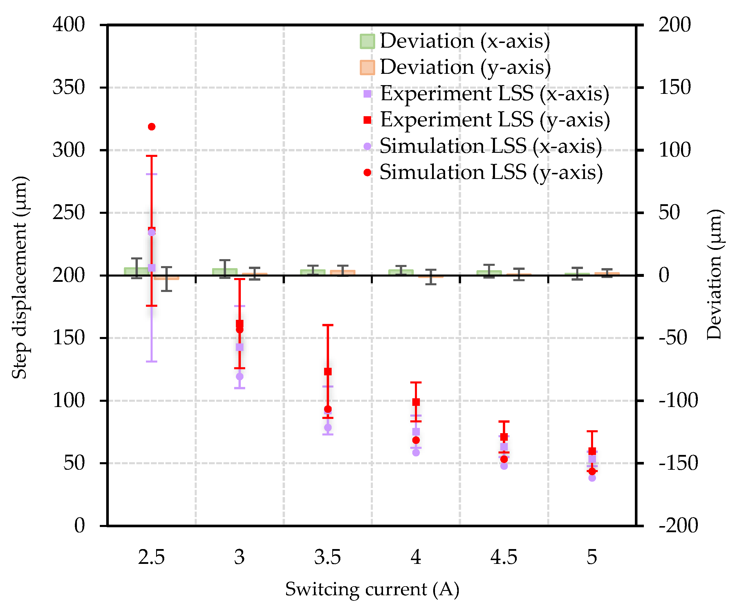
The switching current value is an important actuation parameter which determines electromagnetic force value (Equation (3)) exerted on each MPM, furthermore affects the LSS of the conveyed plate. In this following experiment, the switching current value was set from 2.5 A to 5 A with 20 ms width. When the driving current value is set less than 2.5 A, it has been observed in the experiments that the MPM can hardly be moved due to the insufficient electromagnetic driving force. 5 A current value is the upper-limit current value for the power supply (KA3005D). 20 steps along the x/y-axis were realized for each switching current value to obtain an average LSS value. The results are presented in Figure 11.
It can be observed from Figure 11 that the simulation LSS value is close to the experimental LSS value for both x- and y-axis, and with the increase of switching current value, the experimental LSS value of the conveyed plate decreases as well. This phenomenon can be explained by the decrease of relative movement time between the MPM and the conveyed plate during “slip” process. When the switching current value increases, the electromagnetic forces exerted on each MPM increases at the same time. It results in a decrease in “slip” time (relative movement time) between the MPM and the conveyed plate under the same friction environment, the LSS value then decreases. The standard deviation of the experimental LSS also decreases with the increase of switching current value for both x- and y-axis. This phenomenon can be explained by the important influence of the friction conditions during switching when lower current is applied. This influence of friction conditions reduces with faster switching process as the current value increases.
It can also be observed that there is a difference between the LSS values for x-axis and y-axis, the LSS values for y-axis are higher than LSS values for x-axis with the same switching current value. This difference is caused by the distance between the two orthogonal switching wires (XW and YW). This distance (Figure 1) results in the difference between electromagnetic forces (Equation (3)) exerted on each MPM along x- and y-axis. In addition, the difference between the LSS values (for x-axis and y-axis) decreases with the increase of switching current value for both experiment and simulation. When the switching current value is set 5 A, the mentioned difference of LSS value is the minimum value (6 µm). 5 A switching current is also the suggested switching current value as the average error bar of LSS values (x: 53.53 ± 5.73 µm, y: 59.67 ± 15.94 μm) is the minimum in this experiment which indicates a good repeatability of the LSS.
When the conveyed plate is linearly conveyed along the x-/y-axis, there is a small displacement of the conveyed plate along the undesired perpendicular direction (y-/x-axis). This displacement has been considered as the conveyed plate geometry center deviation along y- and x-axis which has also been presented in Figure 2. The geometry center deviation value of the conveyed plate is indeed small (max: 5.76 µm; min: −2.85 µm) which is lower than the resolution of the camera. The error bar of this geometry center deviation is also lower than the resolution of the camera.
Compared with LSS value (5 A switching current) in the previous study, the standard deviation of LSS value (previous: 19.08 µm, present: 5.73 µm) is reduced by 35.97% based on present micro-fabricated prototype. It is then indicated that the output stability of the micro-conveyor is improved. Moreover, the effectiveness of the micro-fabrication technology is proved.

4.2.2. Influence of Switching Current Value on RSS

Planar rotation is another important application of the micro-conveyor and in this experiment the influence of the switching current value on the RSS has been studied. A total of 20 clockwise rotation steps were realized for each switching current value to obtain an average RSS value. The XW and YW were injected with an equivalent current pulse from 2.5 A to 5 A with 20 ms width via the rotation control strategy mentioned above. The conveyed plate was oriented in the geometric center of the micro-conveyor as is shown in Figure 3.
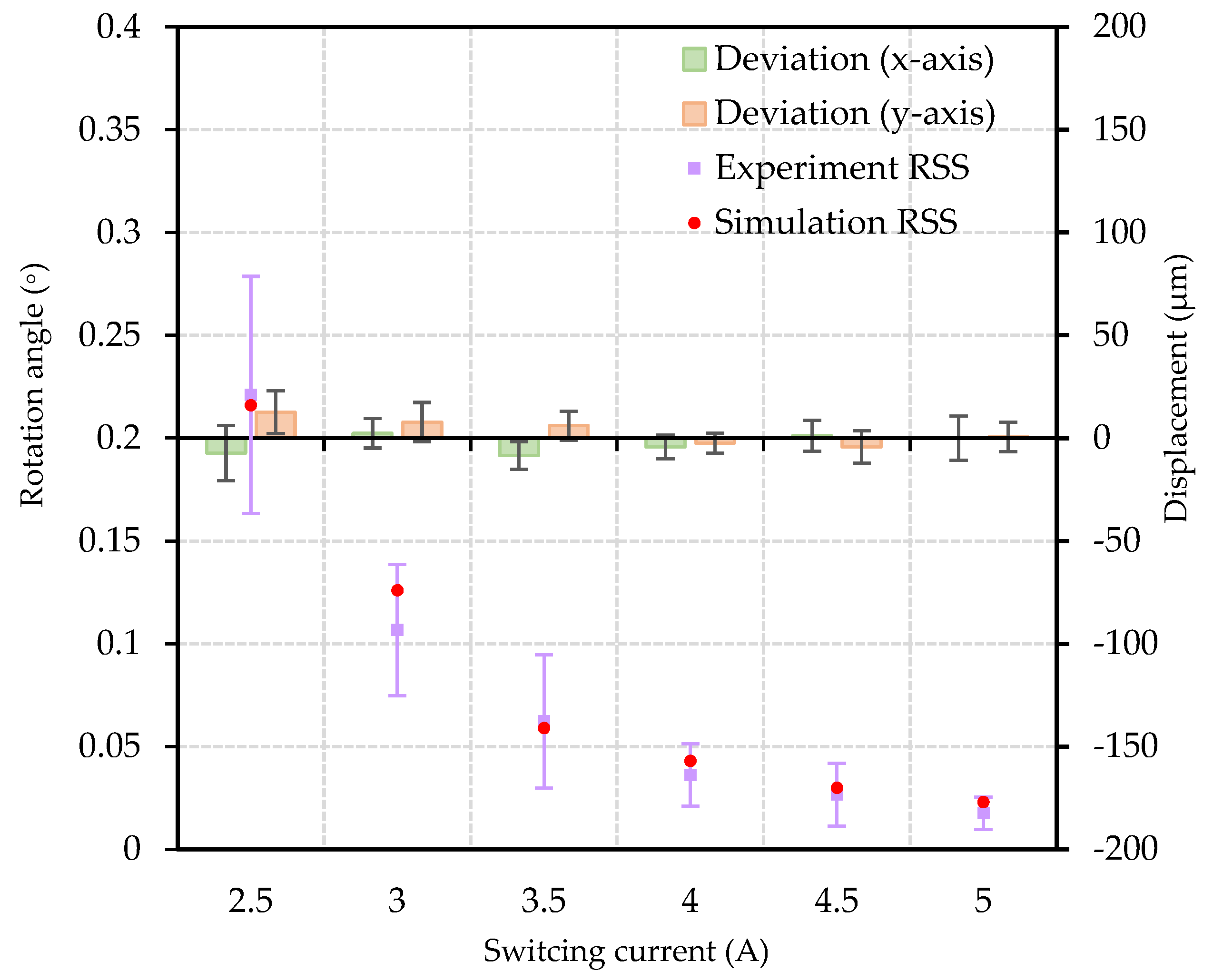
Experimental results have been presented in Figure 12, it can be observed that the experimental and simulation results are almost consistent, the obtained plate RSS value decreases from 0.221 ± 0.058° to 0.018 ± 0.008° when the switching current value increased. The phenomenon can be similarly explained by the decrease of “slip” time (relative movement time) between the MPM and the conveyed plate. The standard deviation of the experimental RSS also decreases with the increase of switching current value. This phenomenon can be explained similarly via the important influence of the friction conditions during switching when lower current is applied. This influence of friction conditions reduces with faster switching process as the current value increases.
When the conveyed plate is rotating, the conveyed plate geometry center deviation along x- and y-axis can be observed and are presented in Figure 12. The phenomenon can be explained by the difference between electromagnetic driving forces (presented in Figure 6) along x- and y-axis under the equivalent current value. This difference results in a “slip” time difference between the x- and y-axis switched MPMs thus the geometry center deviation of the conveyed plate is generated. However, the difference between electromagnetic driving forces is indeed small (presented in Section 3), the geometry center deviation of the conveyed plate during rotation is small (max: 12.66 µm; min: 0 µm). The maximum error bar value of this geometry center deviation is about one pixel dimension.

4.2.3. Loading Capacity Test

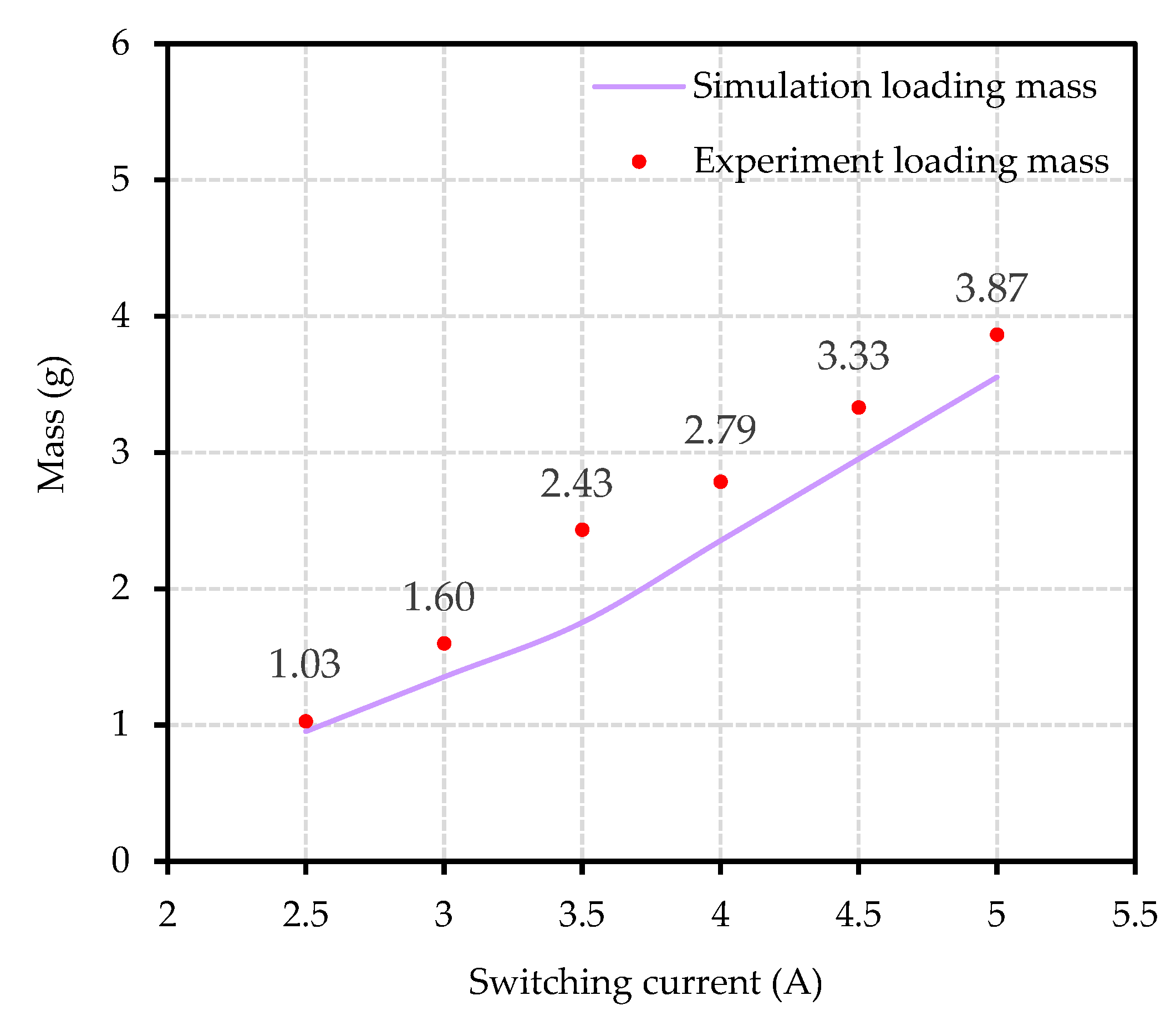
Loading capacity is a significant performance indicator for the micro-conveyor. In this part, the relationship between the maximum loading mass value and the switching currents value is studied (along x-axis). Loading mass was applied in the form of small papers which were attached to the conveyed plate top surface. Experimental results are presented in Figure 13.
It can be observed that the experimental result has the same changing trend with the simulation result, and the maximum loading mass value of the device increases from 1.03 g (corresponding LSS: 166.00 ± 25.90 µm) to 3.87 g (corresponding LSS: 32.85 ± 5.73 µm) as the current increases. This changing trend is reasonable as the increase of switching current value indicates an increase of the electromagnetic switching force which leads to a higher loading mass value.

4.2.4. Influence of the “Backward Motion”

“Backward motion” is a fallback phenomenon which generally exists in stick-slip system and could reduce the positioning precision of the micro-conveyor [28,29]. In the proposed stick-slip control strategy, there is no “backward motion” in the micro-conveyor theoretically. In this experiment, the conveyed plate “backward motion” of the prototype device has been studied to verify the proposed control strategy.
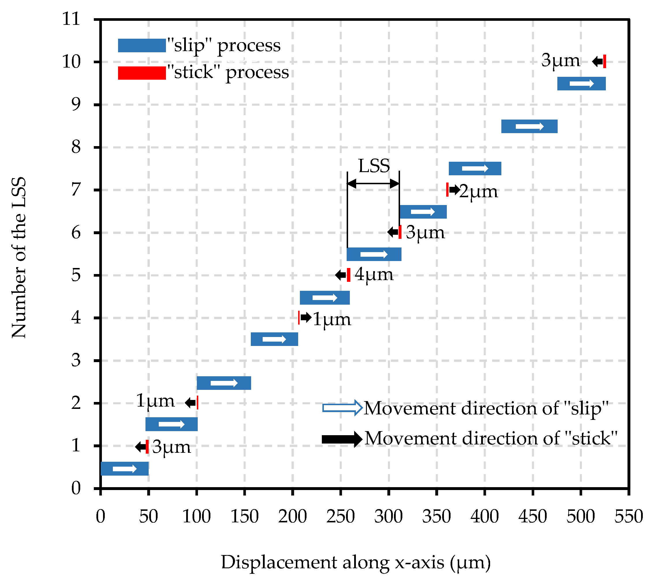
Laser displacement sensor (IL-S025) with high precision (resolution: 1 µm) was used to measure the conveyed plate displacement caused by the possible “backward motion”. Ten consecutive switching process of the conveyed plate displacement was realized via different driving current value respectively. The experimental results upon 5 A switching current value have been selected and presented in Figure 14 for better understanding.
It can be seen from Figure 14 that the conveyed plate displacement has a slight variation (max: 4 µm, min: 0 µm) in “stick” process, and the average variation is 1.1 µm which accounts for only 2.05% of the average SSD value. The generation of the conveyed plate displacement variation in “stick” process is due to the conveyed plate vibration during switching. When the MPMs are switched and arrive at the destination stable position of the square cavity, a slight rigid collision between the MPM and the square cavity border is generated to stop the MPM. This slight rigid collision is then transmitted to the conveyed plate via vibration and the conveyed plate displacement variation is generated.
Experimental tests on the influence of different driving current values to the “backward motion” have also been studied. The conveyed plate average displacement during the “stick” process value have been achieved and presented in Table 5. This value is quite small for all the switching current values (maximum: −1.10 ± 2.02 µm (accounts for 2.05% of the step), minimum: 0.40 ± 1.43 µm (accounts for 0.28% of the step)).
The experimental results mentioned in this subsection prove that the “backward motion” by using the proposed stick-slip control strategy for the prototype design is indeed small. The effectiveness of the control strategy is then verified.

4.2.5. Long-Range Conveyance Test

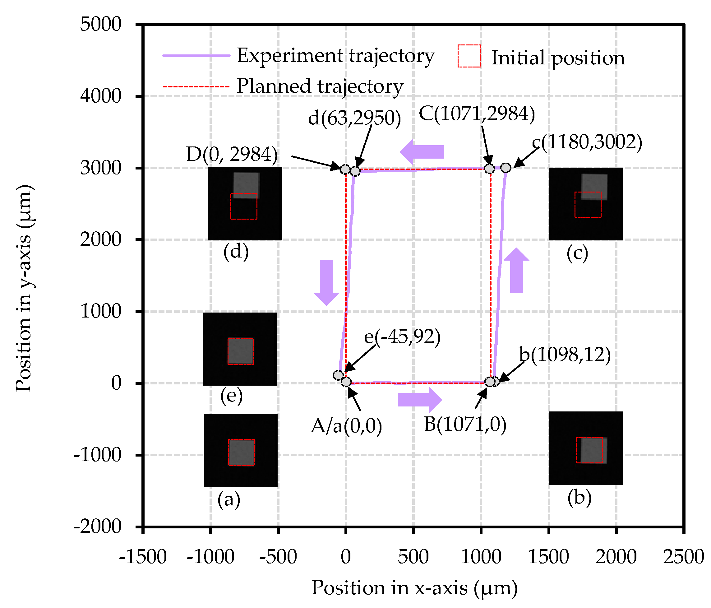
In this part, long-range conveyance along x-and y-axis have been realized to test the planar conveyance performance of the prototype. In this test, the conveyed plate initial position was set to point A (x: 0, y: 0). Four destination points (A, B, C, and D in Figure 15) were set to realize a square closed trajectory long-range conveyance. Points B, C, and D were set (x: 1071, y: 0), (x: 1071, y: 2984), (x: 0, y: 2984) respectively. 5 A switching current value was selected for this experiment.
20 LSS (along x-axis (+)), 50 LSS (along y-axis (+), 20 LSS (along x-axis (-)), and 50 LSS (along y-axis (-)) were implemented one after another to realize the planned square trajectory (A→B→C→D→A). This process was done five times, the mean experimental position of the conveyed plate was obtained for each LSS. The corresponding mean experimental trajectory (a→b→c→d→e) and the trajectory parameters have been presented in Figure 15 and Table 6, respectively.
It can be observed from the Figure 15 that the actual trajectory is almost consistent with the planned trajectory especially in the planned trajectory A→B (actual a→b) part. The average positioning error is 27 µm along x-axis which is 2.5% of the planned conveyance distance with a y-axis average positioning error of 12 µm (presented in Table 6). The average linearity of the experimental trajectory is 97.8% which is a good linearity value. The small average positioning error and the good experimental trajectory linearity indicate a quite well actual conveyance ability along x-axis.
In the planned trajectory B→C part, the average positioning error is 18 µm along y-axis which is only 0.6% of the planned conveyance distance. However, a shifting of the conveyed plate has been observed along x-axis, the corresponding average positioning error is 109 µm. This phenomenon can be explained the accumulation error of conveyed plate geometry center deviation presented in Figure 11. The average linearity of the experimental trajectory (b→c) was 97.3%.
In the planned trajectory C→D part, the average positioning errors are −63 µm along x-axis which is 5.9% of the planed conveyance distance. The average positioning error is −34 µm along y-axis. The average linearity of the experimental trajectory (c→d) is 97.0%.
In the planned trajectory D→A part, the positioning error is 92 µm along y-axis which is 3.1% of the planned conveyance distance. The average positioning error is −45 µm along x-axis. The average linearity of the experimental trajectory (d→e) is 96.5%.
The final average positioning errors are −45 µm and 92 µm along x- and y-axis respectively after 140 LSS (5 times). The average linearity of the experimental trajectory decreases from 97.8% to 96.2% during long conveyance due to the mentioned accumulation of position error. It can be concluded from these experimental results that the proposed micro-conveyor does not have bad conveyance ability for long range conveyance with open-loop control.
Compared with the previous research, improvements have been found in the present prototype micro-conveyor and are presented in Table 7. The present prototype micro-conveyor is able to accomplish the long-range conveyance task along both x- and y-axis. Moreover, the trajectory linearity (along x-axis) of the present prototype is better than the previous device (previous: 84.8%, present: 96.2%) due to the improvement of the fabrication precision. However, the long-range conveyance limitation of the present micro-conveyor is lower than that of the previous device due to the less elementary actuator numbers. This problem can be solved by the scalability of the present design. More elementary actuators can be added to the micro-conveyor in the same array form to enlarge the working area of the micro-conveyor. This approach will be implemented in the future research soon.

4.3. Comparison among This Work and Other Researches

The performance requirement of the micro-conveyor could vary with the geometric dimensions of the object, positioning task, and application where it is implemented. In order to illustrate the characteristics and advantages of this work, a brief comparison among this work and other existing research has been carried out in Table 8. This comparison has been implemented in terms of planner motion capabilities (DoF), active area, driving principle, scalability, working range, load capabilities, and resolution. Through the comparison, the proposed micro-conveyor system has competitive active area, 3-DoF, scalable design, significant working range, medium loading capacity and good conveyance resolution among the digital actuator-based micro-conveyance systems. Judging from the presented performance relative to other micro-conveyance systems, the presented work could find its place among the micro-conveyor system for micro-conveyance applications (e.g., micro-factory) where flexibility (scalability) is needed to adapt to the changing architecture.

5. Conclusions

In this work, the principle of a 3-DoF micro-conveyor consisting of 4 electromagnetic digital actuators was presented. Two different control strategies were adopted to realize the planar 3-DoF conveyance of the device. A static analytical model and a dynamic semi-analytical model based on the principle have been built for the optimal design, analysis, and necessary calculation of a prototype. The experimental prototype was fabricated with the help of micro-fabrication technology and the control system was established. Several experimental tests (focusing on the prototype conveyance application) have been carried out to verify the design principle, and the experimental results have been presented and discussed.
The experimental results show that for planar conveyance application, the output (LSS/RSS value) of the proposed micro-conveyor decreases with the increase of the switching current value. The minimum output LSS and RSS values are 53.53 ± 5.73 µm and 0.018 ± 0.008° respectively by using 5 A switching current. The maximum loading mass value of the device increases with the increase of the switching current value and the maximum load mass value is 3.87 g (by using 5 A switching current). With the analysis of the prototype “stick” and “slip” process experimental results, it has been verified that the influence of the “backward motion” is small in the prototype device by using the proposed control strategies, and the effectiveness of the control strategies has been further confirmed. In the long-range conveyance test, it has been observed that the prototype has a quite good positioning precision with an average position error of (x: −45 µm, y: 92 µm) after 140 LSS, and the average linearity of the experimental trajectory can reach 96.2% under the open-loop control condition.
In addition, compared to the previous study, the micro-conveyor presented in this work has three main advantages: optimal design, fast and precise modeling, and high fabrication precision. These three advantages are reflected in the following four aspects. First, the static magnetic forces exerted on each MPM are more homogeneous in this work. The difference between XY and YW electromagnetic forces is smaller compared to previous study. Second, the high-efficiency of the ADAMS software enables the fast and precise modeling of the micro-conveyor. Third, the stability of the output LSS (previous standard deviation: 19.08 µm, present standard deviation: 5.73 µm) and the linearity during long range conveyance (previous: 84.8%, present: 96.2%) have been improved better in the present work. Last, the third DoF (planar rotation) of micro-conveyor has been realized and lower switching current value can be used for conveyance which indicated less energy consumption during switching for the present work.
The future work can be summarized in three parts. First, a dynamic analytic model will be created based on the present modeling in order to further improve the modeling precision and predict the output LSS. Second, a new optimal version of the micro-conveyor with more elementary actuators will be designed and manufactured to expand the application of the proposed principle. Third, a control algorithm will be built to realize an automatic planned conveyance trajectory for complex conveyance tasks according to the different conveyance requirements (e.g., less energy consumption and high conveyance speed) by using different switching current value.

Author Contributions

Conceptualization, P.H.; methodology, P.H.; software, P.L.; validation, P.H., P.L. and Y.H.; formal analysis, P.L.; investigation, P.L. and Y.H.; resources, P.H.; data curation, P.L., Y.H. and X.C.; writing—original draft preparation, P.L.; writing—review and editing, P.H., P.L. and Y.H.; visualization, P.L.; supervision, P.H.; project administration, P.H.; funding acquisition, P.H. All authors have read and agreed to the published version of the manuscript.

Funding

This research was funded by the scientific research program of Shaanxi Provincial Department of education, grant number 19JK0366.

Data Availability Statement

Not applicable.

Conflicts of Interest

The authors declare no conflict of interest.

References

  1. Quiñones, B.; Zhu, H.; Solovev, A.; Mei, Y.; Gracias, D. Origami Biosystems: 3D Assembly Methods for Biomedical Applications. Adv. Biosys. 2018, 2, 1800230. [Google Scholar] [CrossRef]
  2. Garcia-Gradilla, V.; Orozco, J.; Sattayasamitsathit, S.; Soto, F.; Kuralay, F.; Pourazary, A.; Katzenberg, A.; Gao, W.; Shen, Y.; Wang, J. Functionalized ultrasound-propelled magnetically guided nanomotors: Toward practical biomedical applications. ACS Nano 2013, 7, 9232–9240. [Google Scholar] [CrossRef]
  3. Li, J.; Alfares, A.; Zheng, Y. Optical manipulation and assembly of micro/nanoscale objects on solid substrates. Iscience 2022, 25, 104035. [Google Scholar] [CrossRef]
  4. Malak, S.; Hajjar, H.; Dupont, E.; Khan, M.; Prelle, C.; Lamarque, F. Optical Localization and Tracking Method of a Mobile Micro-Conveyor over a Smart Surface. IEEE Sens. J. 2021, 21, 10618–10627. [Google Scholar] [CrossRef]
  5. Tellers, M.; Pulskamp, J.; Bedair, S.; Rudy, R.; Kierzewski, I.; Polcawich, R.; Bergbreiter, S. Characterization of a piezoelectric MEMS actuator surface toward motion-enabled reconfigurable RF circuits. J. Micromech. Microeng. 2018, 28, 035001. [Google Scholar] [CrossRef]
  6. Gendreau, D.; Gauthier, M.; Hériban, D.; Lutz, P. Modular architecture of the microfactories for automatic micro-assembly. Robot. Comput.-Integr. Manuf. 2010, 26, 354–360. [Google Scholar] [CrossRef] [Green Version]
  7. Zhakypov, Z.; Uzunovic, T.; Nergiz, A.; Baran, E.; Golubovic, E.; Sabanovic, A. Modular and reconfigurable desktop micro-factory for high precision manufacturing. Int. J. Adv. Manuf. Technol. 2017, 90, 3749–3759. [Google Scholar] [CrossRef]
  8. Hosobata, T.; Yamamoto, A.; Higuchi, T. Transparent synchronous electrostatic actuator for long-stroke planar motion. IEEE/ASME Trans. Mechatron. 2014, 20, 1765–1776. [Google Scholar] [CrossRef]
  9. Dao, D.; Pham, P.; Sugiyama, S. Multimodule micro transportation system based on electrostatic comb-drive actuator and ratchet mechanism. J. Microelectromech. Syst. 2010, 20, 140–149. [Google Scholar] [CrossRef]
  10. Yahiaoui, R.; Zeggari, R.; Malapert, J.; Manceau, J. A MEMS-based pneumatic micro-conveyor for planar micromanipulation. Mechatronics 2012, 22, 515–521. [Google Scholar] [CrossRef]
  11. Robertson, M.; Murakami, M.; Felt, W.; Paik, J. A compact modular soft surface with reconfigurable shape and stiffness. IEEE/ASME Trans. Mechatron. 2018, 24, 16–24. [Google Scholar] [CrossRef]
  12. Ruiz-Díez, V.; Ababneh, A.; Seidel, H.; Sánchez-Rojas, J. Design and Characterization of a Planar Micro-Conveyor Device Based on Cooperative Legged Piezoelectric MEMS Resonators. Micromachines 2022, 13, 1202. [Google Scholar] [CrossRef]
  13. Iizuka, T.; Sakai, N.; Fujita, H. Position feedback control using magneto impedance sensors on conveyor with superconducting magnetic levitation. Sens. Actuators A Phys. 2009, 150, 110–115. [Google Scholar] [CrossRef]
  14. Deshmukh, A.; Petit, L.; Khan, M.; Lamarque, F.; Prelle, C. Planar Micro-Positioning Device Based on a 3D Digital Electromagnetic Actuator. Actuators 2021, 10, 310. [Google Scholar] [CrossRef]
  15. Piranda, B.; Laurent, G.; Bourgeois, J.; Clévy, C.; Möbes, S.; Le Fort-Piat, N. A new concept of planar self-reconfigurable modular robot for conveying microparts. Mechatronics 2013, 23, 906–915. [Google Scholar] [CrossRef]
  16. Morkvenaite-Vilkonciene, I.; Bucinskas, V.; Subaciute-Zemaitiene, J.; Sutinys, E.; Virzonis, D.; Dzedzickis, A. Development of electrostatic microactuators: 5-year progress in modeling, design, and applications. Micromachines 2022, 13, 1256. [Google Scholar] [CrossRef]
  17. Cai, T.; Fang, Y.; Fang, Y.; Li, R.; Yu, Y.; Huang, M. Electrostatic pull-in application in flexible devices: A review. Beilstein J. Nanotechnol. 2022, 13, 390–403. [Google Scholar] [CrossRef] [PubMed]
  18. Mabed, H.; Dedu, E. Short and long term optimization for micro-object conveying with air-jet modular distributed system. J. Parallel Distrib. Comput. 2020, 144, 98–108. [Google Scholar] [CrossRef]
  19. Fukuta, Y.; Chapuis, Y.; Mita, Y.; Fujita, H. Design, fabrication, and control of MEMS-based actuator arrays for air-flow distributed micromanipulation. J. Microelectromech. Syst. 2006, 15, 912–926. [Google Scholar] [CrossRef]
  20. Chen, Y.; Chen, Y.; Huang, C. Nano-scale positioning design with piezoelectric materials. Micromachines 2017, 8, 360. [Google Scholar] [CrossRef] [PubMed]
  21. Dong, J.; Zhang, B.; Li, X.; Xu, Z.; Wang, J.; Liu, C.; Cao, Y. A stick-slip piezoelectric actuator with suppressed backward motion achieved using an active locking mechanism (ALM). Smart Mater. Struct. 2021, 30, 095015. [Google Scholar] [CrossRef]
  22. Meessen, K.; Paulides, J.; Lomonova, E. Analysis of a novel magnetization pattern for 2-DoF rotary-linear actuators. IEEE Trans. Magn. 2012, 48, 3867–3870. [Google Scholar] [CrossRef]
  23. Jansen, J.; Van-Lierop, C.; Lomonova, E.; Vandenput, A. Magnetically levitated planar actuator with moving magnets. IEEE Trans. Ind. Appl. 2008, 44, 1108–1115. [Google Scholar] [CrossRef] [Green Version]
  24. Huyan, P.; Huang, Y.; Li, P.; Cui, X.; Petit, L.; Prelle, C. Experimental Characterization of a Stick-Slip Driving Micro Conveyance Device Consisting of Digital Actuators. Actuators 2022, 4, 112. [Google Scholar] [CrossRef]
  25. Furlani, E.P. Permanent Magnet and Electromechanical Devices; Furlani, E.P., Ed.; Academic Press: San Diego, CA, USA, 2001. [Google Scholar]
  26. Hu, X.; Zhen, Z.; Sun, G.; Wang, Q.; Huang, Q. Improvement on the uniformity of deep reactive ion etch for electrically isolated silicon-based substrates. J. Micromech. Microeng. 2022, 32, 045005. [Google Scholar] [CrossRef]
  27. Jin, Y.; Wei, W. Image edge enhancement detection method of human-computer interaction interface based on machine vision technology. Mob. Netw. Appl. 2022, 27, 775–783. [Google Scholar] [CrossRef]
  28. Liu, Y.; Xu, Z.; Li, X.; Sun, W.; Huang, H. A high-performance stick-slip piezoelectric actuator achieved by using the double-stator cooperative motion mode (DCMM). Mech. Syst. Signal Process. 2022, 172, 108999. [Google Scholar] [CrossRef]
  29. Qin, F.; Tian, L.; Huang, H.; Wang, J.; Liang, T.; Zu, X.; Zhao, H. Actively controlling the contact force of a stick-slip piezoelectric linear actuator by a composite flexible hinge. Sens. Actuators A Phys. 2019, 299, 111606. [Google Scholar] [CrossRef]
Figure 1. (a) Top view of the elementary digital actuator. (b) Cross-section view A-A of the elementary digital actuator. (c) Top view of micro-conveyor. (d) Schematic view of the micro-conveyor.
Actuators 11 00294 g001
Figure 2. Illustration of linear control strategy. (a) Initial position. (b) “slip” process. (c) to (d) “stick” process. (e) Control signal.
Actuators 11 00294 g002
Figure 3. Illustration of rotation control strategy. (a) Initial position. (b) “Slip” process. (c) to (d) “stick” process. (e) Control signal.
Actuators 11 00294 g003
Figure 4. Magnets and coordinate system illustrated for static magnetic force and electromagnetic force calculation.
Actuators 11 00294 g004
Figure 5. Representation of the static magnetic force: (a) static magnetic force along x-axis direction; (b) static magnetic force along y-axis direction.
Actuators 11 00294 g005
Figure 6. Representation of the electromagnetic force: (a) the horizontal electromagnetic force in the stroke; (b) the vertical electromagnetic force within the stroke.
Actuators 11 00294 g006
Figure 7. The virtual prototype of the proposed micro-conveyor in ADAMS.
Actuators 11 00294 g007
Figure 8. The micro-fabricated prototype base.
Actuators 11 00294 g008
Figure 9. Device control system.
Actuators 11 00294 g009
Figure 10. The square marker pasted on the conveyed plate and image post-processing: (a) the conveyed plate, (b) original image, (c) edge detected image, (d) edge fitting and center determine image.
Actuators 11 00294 g010
Figure 11. Influence of switching current on the conveyed plate LSS along x/y-axis.
Actuators 11 00294 g011
Figure 12. Influence of switching current on the conveyed plate RSS.
Actuators 11 00294 g012
Figure 13. Maximum loading mass value for different switching current.
Actuators 11 00294 g013
Figure 14. Ten consecutive switching process of the conveyed plate displacement at 5 A switching current value.
Actuators 11 00294 g014
Figure 15. Experiment trajectory of the conveyed plate in the long-range conveyance.
Actuators 11 00294 g015
Table 1. The dimensions and properties of the micro-conveyor.
ElementDimensions (mm)Mass (g)MaterialMag (T)
MPM2.45 × 2.45 × 1.550.072NdFeB1.4
FPM2.45 × 2.45 × 0.950.040NdFeB1.4
BPM1.85 × 1.85 × 0.950.023NdFeB1.4
Base80.00 × 80.00 × 1.2510.025Silicon-
Conveyed plate40.00 × 40.00 × 0.160.657Silica-
Thin glass layer80.00 × 80.00 × 0.162.628Silica-
PCB80.00 × 80.00 × 0.102.761Polyethylene terephthalate-
ParameterDistance betweenValue (mm)
D1Cavity and FPM10.00
D2Elementary actuator20.00
D3Cavity and BPM11.72
d1XW and MPM0.18
d2YW and MPM0.24
Stroke-0.20
Table 2. Magnetic forces comparison between the previous and present design.
Static Magnetic Force
Aspect 1
ComparisonPrevious designPresent design
Average static magnetic force (mN)0.624 ± 0.059 (9.46%)1.031 ± 0.007 (0.68%)
Aspect 2
ComparisonPrevious designPresent design
Stable position12341234
Static magnetic force (mN)0.6280.5710.6050.6941.0341.0271.0281.036
Maximum Variation (mN)0.1230.009
Electromagnetic force
ComparisonPrevious designPresent design
Electromagnetic force for 1 A (mN)0.97 mN (XW)/0.73 mN (YW)0.84 mN (XW)/0.78 mN (YW)
Difference between XW and YW (mN)0.24 mN0.06 mN
Table 3. Components constraint relations and material properties.
ElementConstraintElastic ModulusPoisson’s Ratio
MPMMobile pair160 GPa0.24
BaseFixed pair190 GPa0.27
Conveyed plateContact55 GPa0.25
Thin glass layerFixed pair55 GPa0.25
Coulomb friction elementsFriction coefficient
MPM and Base μ s = 0.40, μ k = 0.32
MPM and Conveyed plate μ s = 0.35, μ k = 0.28
MPM and Thin glass layer μ s = 0.35, μ k = 0.28
Contact parametersValue
Stiffness1.6 × 105 N/mm
Exponent1.4
Table 4. Influence of the manufacturing errors on static magnetic force.
Previous DesignPresent Design
Manufacturing methodConventional fabricationMicro-fabrication
Manufacturing Error (µm)+9 to +50−4.52 to +8.03
Static magnetic force
variation (mN)
+0.028 to +0.158−0.029 to +0.041
Relative variation+4.48% to +25.28%−2.81% to +3.98%
Table 5. Average displacement during the “stick” process for different switching current value.
Current Value (A)Displacement (µm)
2.5−1.40 ± 1.35
30.40 ± 1.43
3.5−0.60 ± 1.17
4−1.30 ± 0.67
4.50.62 ± 1.43
5−1.10 ± 2.02
Table 6. The trajectory parameters.
TrajectoryA→Ba→bB→Cb→cC→Dc→dD→Ad→e
Displacement along x-axis (µm)10711098082107111170108
Displacement along y-axis (µm)012298430660−3429842858
Average Positioning error (x-/y-axis) (µm)27/12109/18−63/−34−45/92
Average Linearity-97.8%-97.3%-97.0%-96.2%
Table 7. Compared with the previous research in experiment.
ComparisonDoFLSS (5 A Current)The Linearity of Long-Range Conveyance
Previous240.88 ± 19.03 µm84.8%
Present353.53 ± 5.73 µm96.2%
Table 8. Literature comparison.
DoFActive AreaActuatorScalabilityRangeLoadResolution
[8]2132 × 132 mm2electrostaticNo-18 g400 µm
[9]110 × 10 mm2electrostaticNo<10 mm-10 µm
[10]29 × 9 mm2pneumaticNo<9 mm2 mg1.2 mm
[11]293 × 110 mm2pneumaticNo-739 g26 mm
[5]22 × 5 mm2piezoelectricYes<5 mm
2π rad
2 mg-
[12]25 × 1 mm2piezoelectricNo3 mm100 mg0.1 μm
[13]212 mm × 12 mmelectromagneticNo12 mm0.38 g1.2 mm
Present345 × 45 mm2electromagneticYes42.45 mm
2π rad
3.87 g53.53 µm
50 μrad
Publisher’s Note: MDPI stays neutral with regard to jurisdictional claims in published maps and institutional affiliations.