Article

Design of an Acoustic Synthetic Jet Actuator for Flow Control

1
High Speed Aerodynamics Institute, China Aerodynamics Research and Development Center, Mianyang 621000, China
2
School of Aeronautics, Northwestern Polytechnical University, Xi’an 710072, China
3
Computational Aerodynamics Institute, China Aerodynamics Research and Development Center, Mianyang 621000, China
*
Author to whom correspondence should be addressed.
Actuators 2022, 11(10), 300; https://doi.org/10.3390/act11100300
Submission received: 13 September 2022 / Revised: 14 October 2022 / Accepted: 17 October 2022 / Published: 18 October 2022
(This article belongs to the Section Aircraft Actuators)

Abstract

:
Synthetic jet technology is widely adopted in active flow control. An actuator with an oscillating diaphragm is a commonly used excitation device for synthetic jet generation. However, it has a disadvantage wherein the volume at the cross-section of the cavity varies unevenly when the diaphragm vibrates, which makes it difficult to use multiple jets corresponding to one diaphragm. In this paper, an acoustic synthetic jet actuator that can generate multiple jets with one diaphragm was designed. The diaphragm vibrated in a cylindrical cavity, transferring air to another constant-volume square cavity through pipes. The square cavity was covered with a multiple-orifice plate for the expulsion and suction of the ambient air. Through this means, the implementation of multiple jets corresponding to one diaphragm was achieved. The multiple jets are called distributed synthetic jets in this paper. Governing parameters that determined the performance of the distributed synthetic jets were given by theoretical derivation. It was found that, under specific geometry conditions, the governing parameters were mainly the frequency and voltage of the input signal to the actuator. Then, the velocity characteristics of the distributed synthetic jets were measured by using a constant-temperature anemometer and the parameter space was determined. The results showed that it was practicable to apply the acoustic actuator to turbulent boundary layer flow control.

1. Introduction

A synthetic jet [1,2] is an active flow control technology developed in the 1990s, and it was introduced by Glezer in the literature [3]. Many studies have been conducted on the operating principle [3], formation criteria [4], governing parameters [5], and flow field characteristics [6] of synthetic jets. Synthetic jets belong to the category of zero-net-mass flux jet in essence; they only transfer momentum to the external flow during the operation. Thus, synthetic jets can eliminate the disadvantages of conventional flow control technologies, such as continuous jets and pulsed jets, which need an additional external fluid supply and complicated pipeline conveying system. In addition, there are substantial vortical structures ranging from the integral length scale to micro scale in the synthetic jet, which makes it highly effective for active flow control. Due to these features, synthetic jet technology has a very broad range of applications in various flow control fields, such as flow separation control [7], aerodynamic control [8,9], jet vector control [10], mixing enhancement [11], heat and mass transfer enhancement [12], and noise suppression [13].
An actuator is of great importance in the generation of a synthetic jet, and its original design and working performance directly determine the application effect of the synthetic jet in flow control. The main components of the synthetic jet actuator are the cavity with an opening and the oscillating component, such as a diaphragm or piston. The periodic back-and-forth movement of the oscillating component causes the ambient fluid of the cavity opening to be alternately sucked into and blown out of the cavity, and, through this means, the synthetic jet is generated. Therefore, to some extent, the oscillating component is the core component of the synthetic jet actuator, and its oscillation property plays a decisive role in the volume change of the cavity and thus the velocity characteristic of the synthetic jet. Synthetic jet actuators can be categorized depending on the form of the oscillating component. The actuators that are commonly used include the piezoelectric type [13], the piston type [14], the acoustic type [15,16,17], the polymer film type [18], the shape memory alloy type [19], the electric spark type [20], the plasma type [21], and the electromagnetic type [22]. Different types of synthetic jet actuators have their own characteristics, which are mainly shown in the operating frequency and energy intensity of the synthetic jet, the size and complexity of the actuation device, and the design, manufacture cost, and energy efficiency of the actuation system. Zhong et al. [23,24] performed detailed experimental studies on the characteristics of synthetic jets in quiescent air and boundary layer flow, respectively, aiming at the application of synthetic jet technology in flow separation control under full-scale flight conditions. The design criteria of synthetic jet actuators suitable for full-scale flight conditions were proposed according to the studies.
A convenient approach used to generate a synthetic jet is by using an oscillating diaphragm. This procedure was introduced by Tang and Zhong [25]. The synthetic jet actuator had a cylindrical cavity with an oscillating diaphragm at its bottom. On the top was a circular orifice plate. For an orifice whose diameter was specified, the performance of the actuator was mainly determined by the oscillation frequency and the maximum oscillation amplitude of the diaphragm. A synthetic jet actuator with an oscillating diaphragm is easy to implement. Many studies have adopted the strategy of one diaphragm corresponding to one orifice [15,26,27,28,29,30]. Palumbo and Luca [31] designed a piezo-driven synthetic jet in a double-orifice configuration, which aimed at the optimization of arrays of synthetic jets for separation control. Chaudhari et al. [32] used a multi-orifice synthetic jet for improving impingement heat transfer. Mangate et al. [33] conducted experiments to investigate thermal and flow characteristics of a synthetic jet with multiple orifices of different shapes. However, during the oscillation of the diaphragm, the oscillation amplitude is not the same everywhere across the cross-sectional area of the cavity, which leads to uneven acceleration of the air in the cavity. This makes it difficult to use multiple orifices corresponding to one diaphragm. Gil et al. [34,35] proposed one possible way. They placed 8 or 16 orifices at equal angular intervals on the cylindrical surface of the outer ring surrounding the loudspeaker diaphragm, which provided complete symmetry, so that multiple jets could be generated from a single diaphragm. The velocity characteristics were compared from randomly chosen orifices and the results were very similar. Another way is to place orifices on an inner ring whose diameter is smaller than that of the diaphragm. However, the symmetry fails if two or more inner rings are needed. Moreover, for a plate with a multi-orifice arrangement, the realization of uniform velocity characteristics is more of a problem.
In the present paper, a design that uses multiple orifices corresponding to one diaphragm was proposed. A loudspeaker-driven synthetic jet actuator was assembled at first. The loudspeaker was covered and fastened with a cylindrical cavity. On the top of the cavity was an orifice connected with a rigid plexiglass round tube. The cylindrical cavity was connected to another square cavity with a series of pipes. The square cavity was covered with a distributed synthetic jet array that contained 893 orifices arranged in a 47 row × 19 column square section. As the diaphragm of the loudspeaker oscillated, the volume of the cylindrical cavity varied; however, the volume of the square cavity remained fixed. In this way, the implementation of multiple jets corresponding to one diaphragm was achieved. Characteristics of the distributed synthetic jets developed in the present paper were measured by a constant-temperature anemometer, which offered potential application in turbulent boundary layer flow control.

2. Acoustic Synthetic Jet Actuator

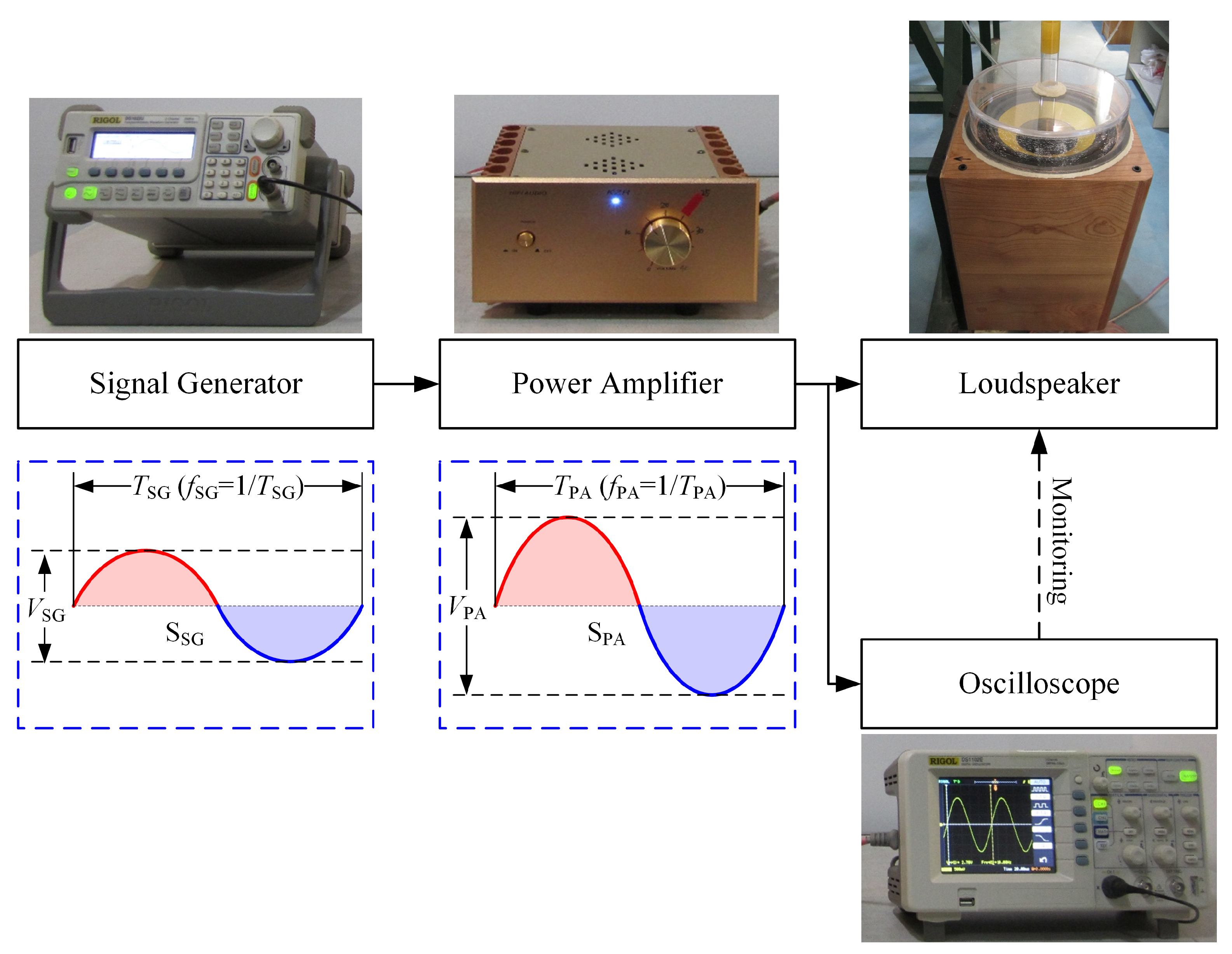
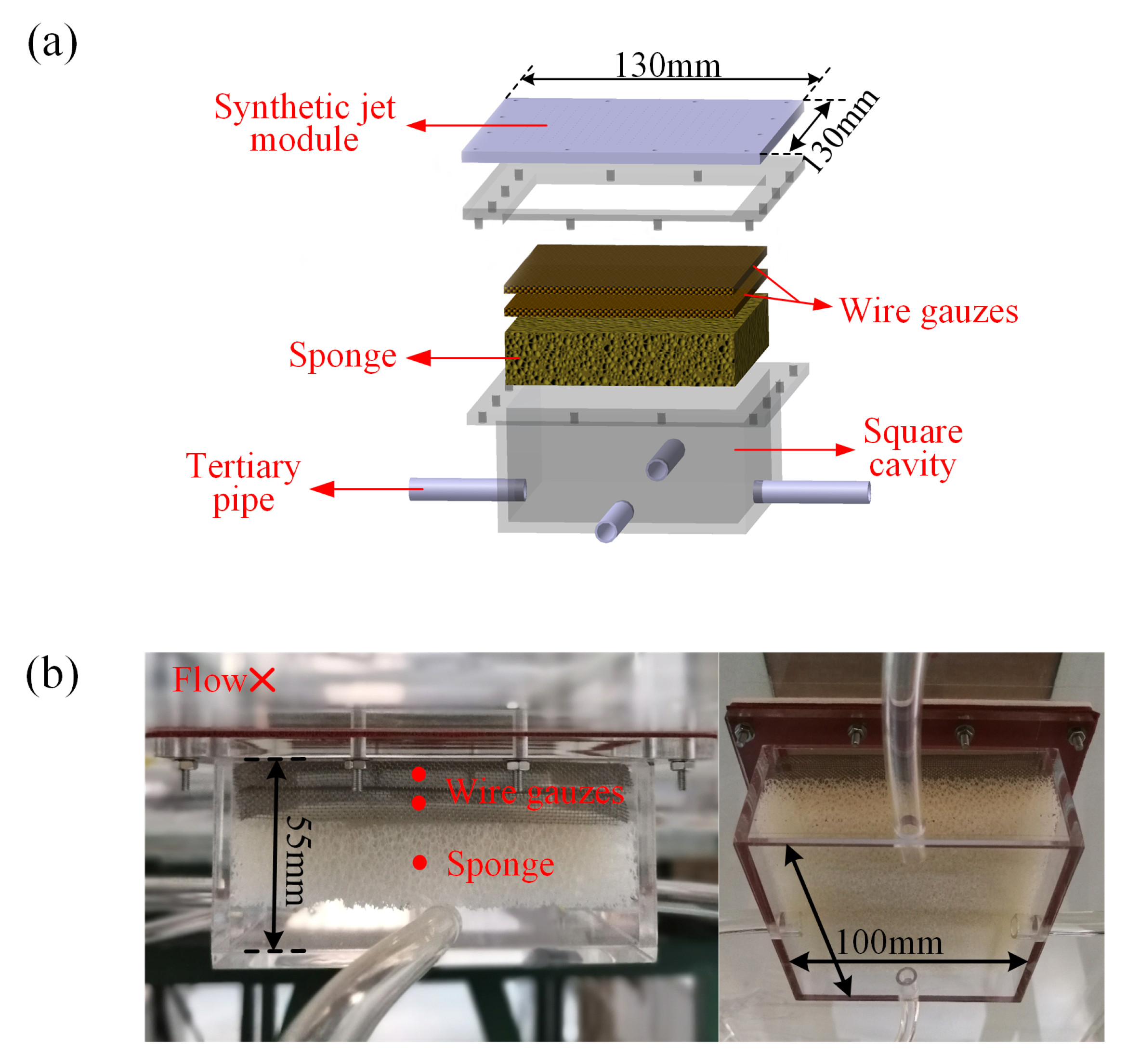
2.1. Actuation System

As shown in Figure 1, the actuation system mainly consisted of a signal generator (RIGOL DG1021), a power amplifier (KZR HIFI-02), and a loudspeaker (HIVI-K10). An oscilloscope (RIGOL DS1102E) was supplemented to monitor the input signal to the loudspeaker. The loudspeaker with an oscillating diaphragm played the role of the synthetic jet actuator, which was the core component of the actuation system. The loudspeaker’s nominal impedance was 5 Ω , nominal power was 150 W, resonance frequency was 32 Hz , and sensitivity ( 2.83 V/1 m) was 88 dB. The diaphragm mass and area were 54.1 g and 0.333 m2, respectively.
The actuation system operated through the procedure illustrated in Figure 1. The signal generator initiated an original sinusoidal signal S SG , which was of a fixed frequency f SG and a low voltage V SG . The offset and the initial phase of S SG were both equal to zero. The original signal S SG was transmitted to the power amplifier and enhanced at a magnification A PA , generating a new sinusoidal signal S PA of a fixed frequency f PA = f SG and a high voltage V PA = A PA × V SG . Following this procedure, a stable output signal S PA was generated, which was also the input signal S in to the loudspeaker. The S PA , monitored by the oscilloscope, was transmitted to the loudspeaker, driving the loudspeaker to operate. Uncertainty in the individual parameter measured was taken based on the resolution of the instrument used to make the measurement. For example, the voltage was monitored by the RIGOL DE1102E oscilloscope. The accuracy of RIGOL DE1102E used to measure voltage is ± 3 % × r e a d i n g . Hence, the uncertainty in the measurement of voltage is ± 3 % .

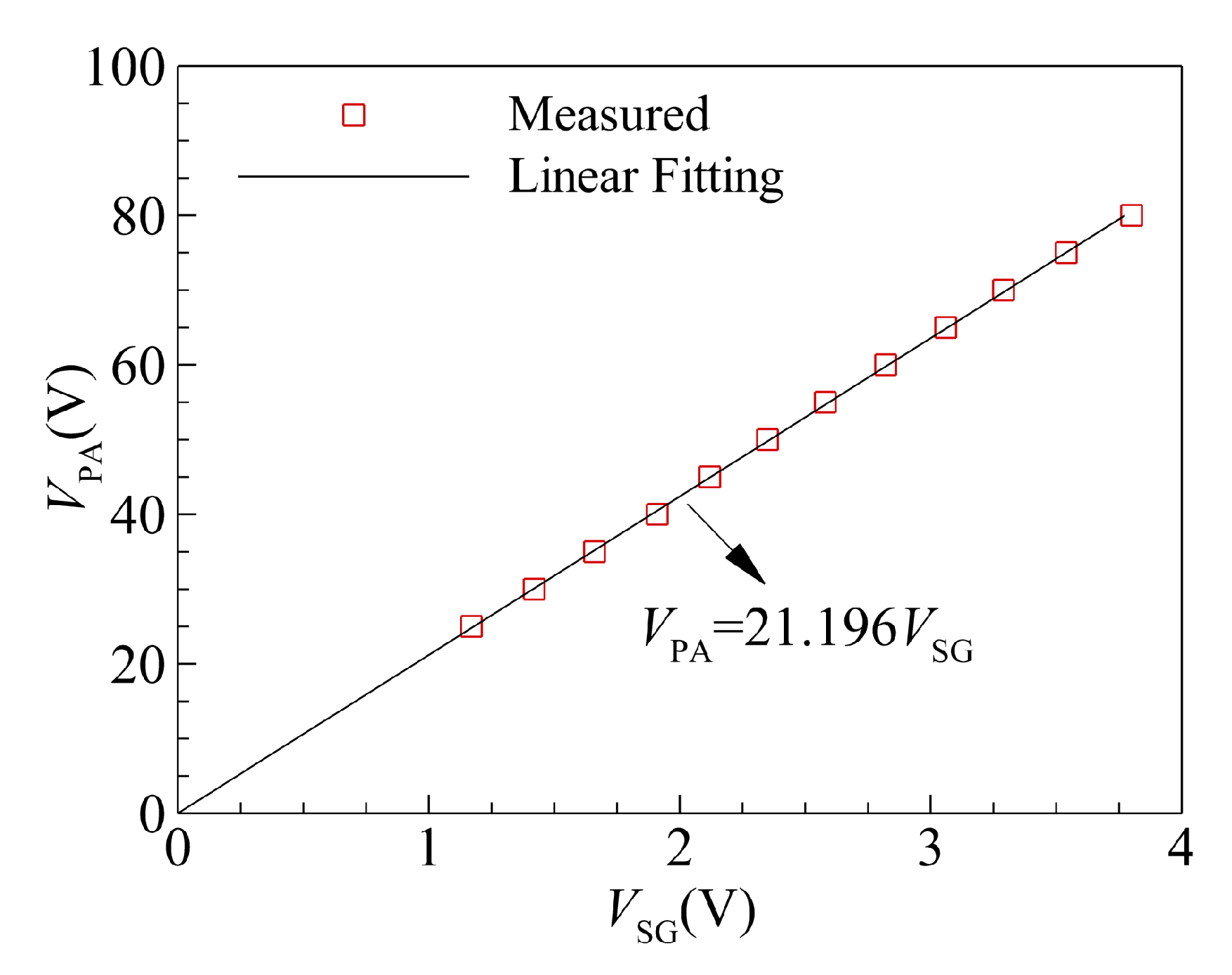
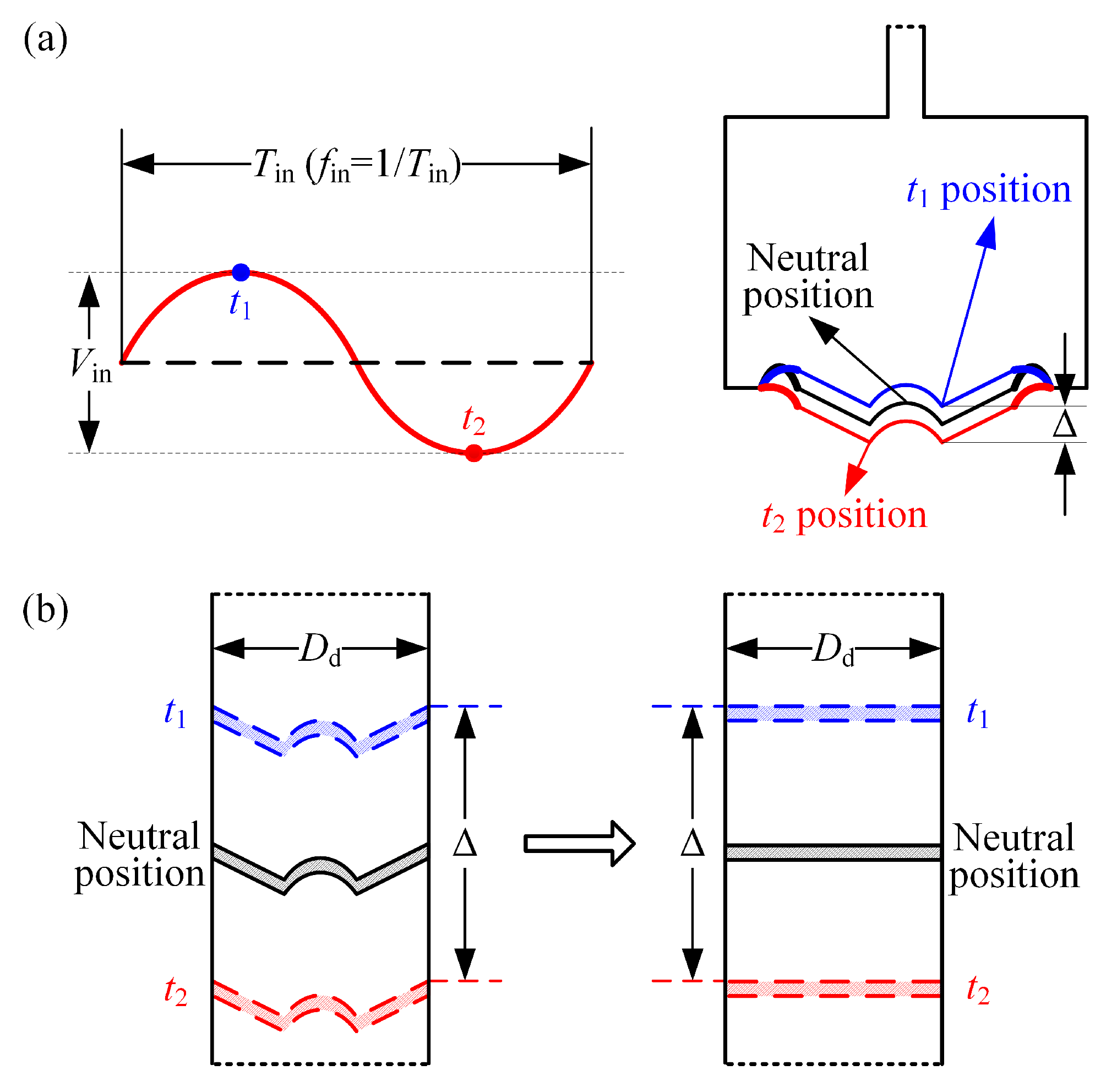
2.2. Input Signal Modulation

The signal generator and the power amplifier were the driving source of the synthetic jet actuator. The frequency of the input signal S in to the loudspeaker was determined as f in = f PA = f SG , and the voltage, which was also referred to as the amplitude, was determined as V in = V PA = A PA × V SG , where A PA was the magnification of the power amplifier and V SG was the input voltage of the original sinusoidal signal S SG . In order to obtain a specific voltage V PA , two methods could be used. The first method was to set V SG to a fixed value, and to regulate A PA . The second method was to set A PA to a fixed value, and to regulate V SG . In the present experiment, the magnification A PA of the power amplifier (KZR HIFI-02) could not be continuously regulated; there were 40 non-zero gears to be selected, i.e., G PA = 1 , 2 , , 40 , whereas the voltage V SG of the signal generator could be continuously regulated with the precision of 0.001   V . Therefore, the input signal to the loudspeaker was modulated with the second method.
During the commissioning of the actuation system, we found that the maximum fidelity peak-to-peak amplitude of S PA was around 83 V , and the maximum peak-to-peak amplitude of S SG was 20 V . If the maximum peak-to-peak amplitude of S PA was set to 80 V , then the magnification A PA of the power amplifier had to be greater than 4. The gear G PA = 25 was selected to determine the value of the magnification A PA . A series of discrete data V SG , i , V PA , i were obtained by regulating V SG of the signal generator and reading the value of V PA displayed by the oscilloscope at a fixed frequency f SG . A linear fitting was processed for these discrete data, together with the origin 0 , 0 , and the result is shown in Figure 2. The slope of the fitting line was equal to the value of A PA ; thus, A PA was determined to be 21.196 through this linear fitting. Then, the input signal S in to the loudspeaker was modulated as
f in = f SG V in = 21.196 V SG

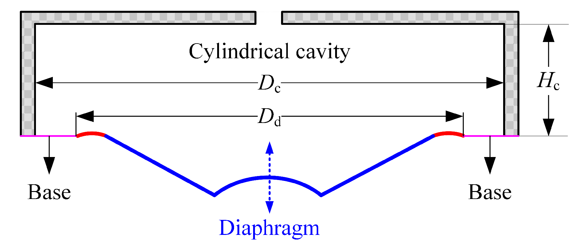
2.3. Implementation of Multiple Orifices Corresponding to One Diaphragm
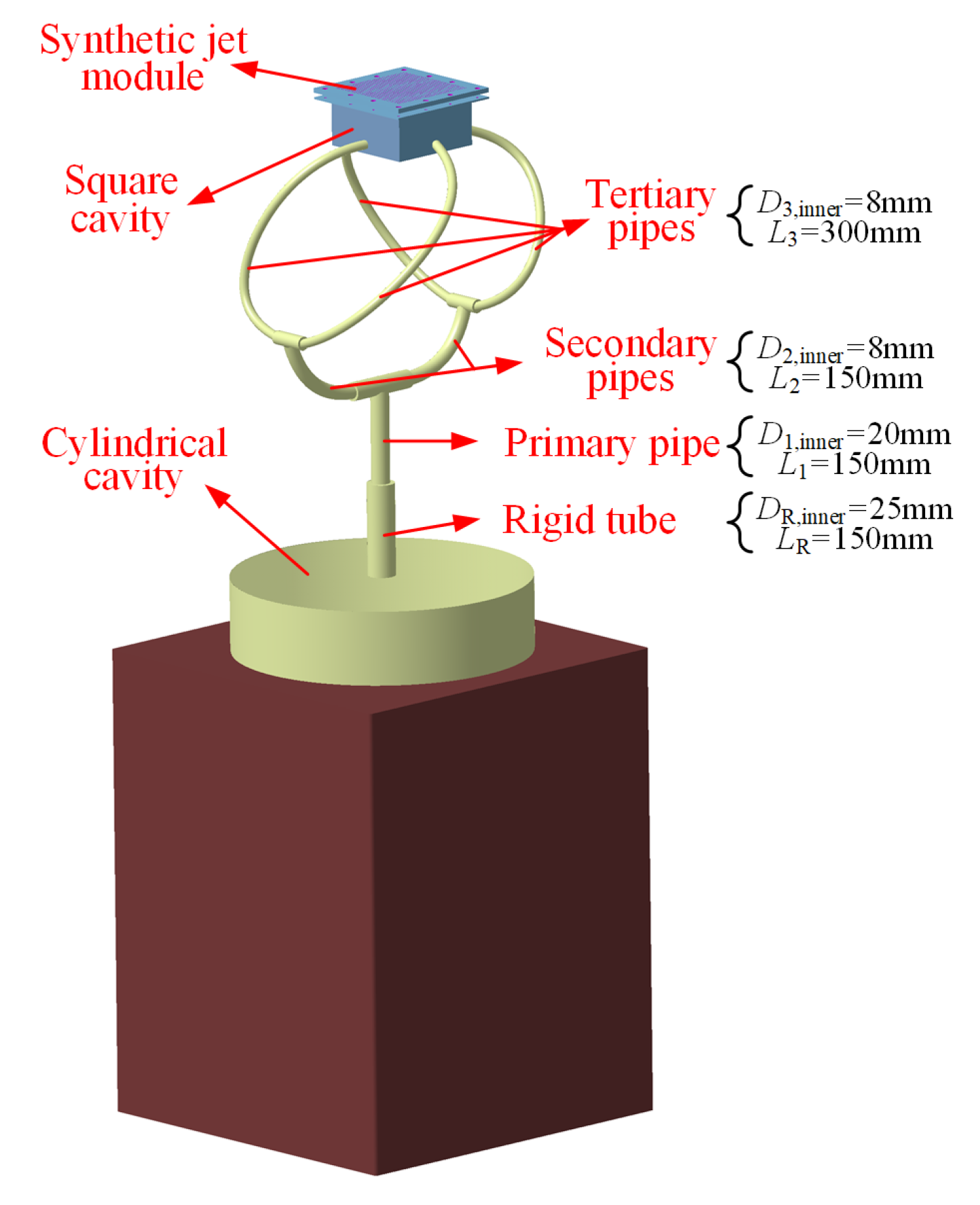
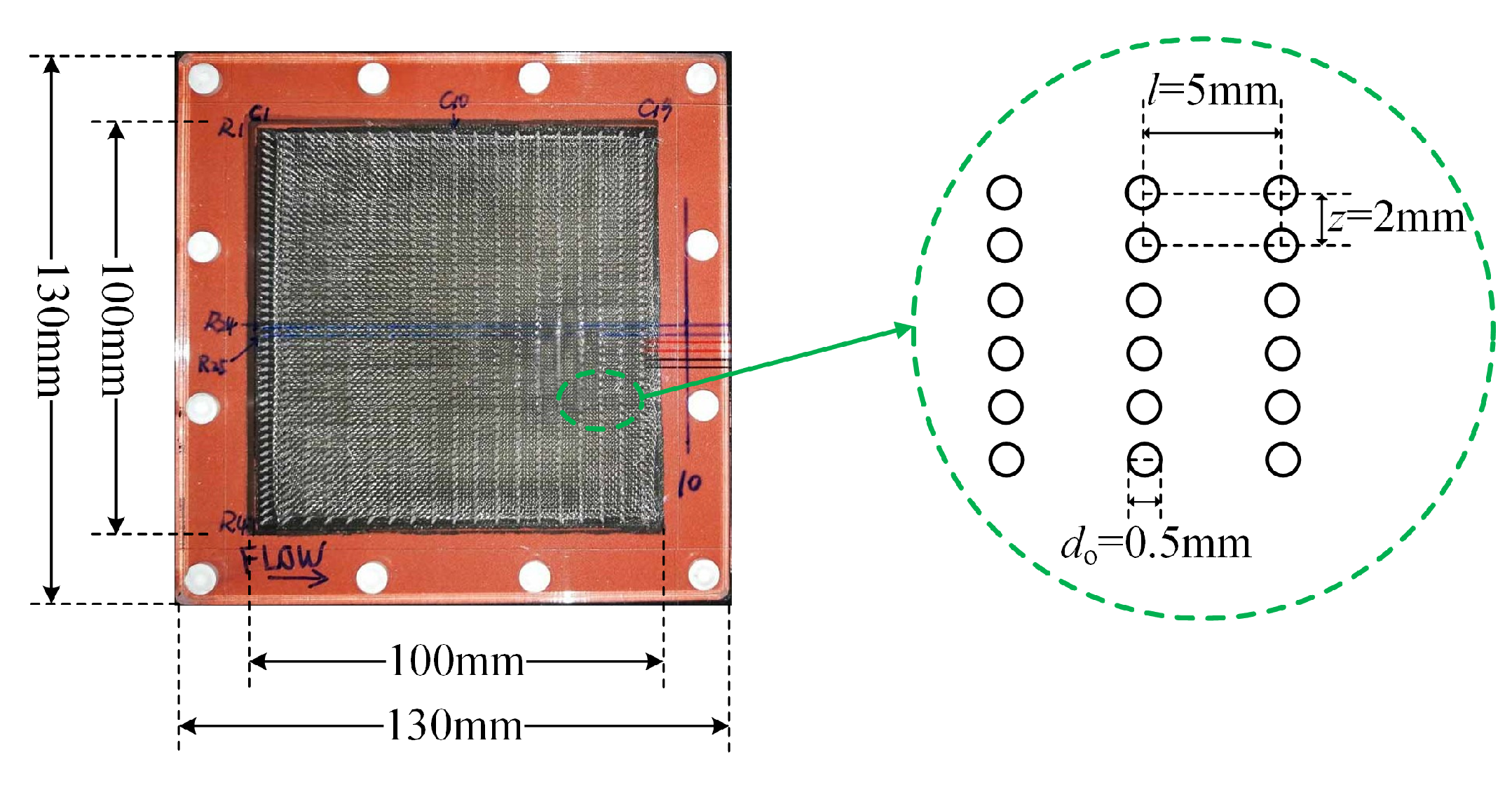
A synthetic jet actuator with an oscillating diaphragm is easy to implement. However, there is one disadvantage of this type of diaphragm actuator. Figure 3 shows a schematic of the diaphragm and cylindrical cavity in the actuation system. During the oscillation of the diaphragm, it cannot achieve the same oscillation amplitude everywhere across the cavity cross-sectional area due to its 360-degree fixation, which will lead to uneven acceleration of the air in the cavity. Therefore, it is usually very difficult to use multiple orifices corresponding to one diaphragm.
In the present paper, a design was proposed to use multiple orifices corresponding to one diaphragm. The primary principle of the design was to transfer the air from the large cylindrical cavity that covered the diaphragm to a small square cavity that was covered with a plexiglass plate of multiple orifices through pipes. The small square cavity was simply a cavity; it had a fixed volume that would not change with the back-and-forth oscillation of the diaphragm. However, the pressure in the small square cavity would change as the diaphragm vibrated, which caused a periodic expulsion and suction of the ambient air through the orifices. Through this means, the distributed synthetic jets were generated.
Figure 4 shows the schematic of the implementation of multiple orifices corresponding to one diaphragm. The loudspeaker was covered and fastened with a cylindrical cavity. The diameter and the height of the cavity were 264 mm and 60 mm, respectively. On the top of the cylindrical cavity was an orifice connected with a rigid plexiglass round tube. The rigid tube was connected with a primary pipe, and the primary pipe was connected with another two secondary pipes via a tee joint. In a similar manner, the secondary pipe was connected with another two tertiary pipes via a tee joint. This arrangement created four outlets for the air from the large cylindrical cavity. The inner diameters of the rigid tube and the primary, secondary, and tertiary pipes were 25 mm, 20 mm, 8 mm, and 8 mm, respectively, and the lengths were 150 mm, 150 mm, 150 mm, and 300 mm, respectively. As the diaphragm of the loudspeaker oscillated, the four tertiary pipes transferred the air into a small square cavity from four sides. The small square cavity had a length of 100 mm, a width of 100 mm, and a height of 55 mm, and it was filled with a thick sponge and two layers of wire gauze to make the airflow uniform, as shown in Figure 5. A plexiglass synthetic-jet-module plate measuring 130 mm (length) × 130 mm (width) × 10 mm (thickness) covered the square cavity. In the middle of the synthetic-jet-module plate, a zone measuring 100 mm (length) × 100 mm (width), which corresponded to the dimensions of the square cavity, was specified for the arrangement of multiple orifices that formed the distributed synthetic jet array. The change in pressure in the square cavity as the diaphragm vibrated would cause the periodic expulsion and suction of the ambient air through the orifices, and the synthetic jets would be produced. In this way, it becomes possible to use multiple orifices corresponding to one diaphragm.

2.4. Orifice Array

Skin-friction drag reduction in turbulent boundary layer is very important for aircraft design, but the technology readiness level is only up to TRL2 in this field. From an aircraft-design point of view, the synthetic jets array is of more practical value in engineering when applied on aircraft surfaces. The actuator and the corresponding multiple orifices were designed to generate synthetic jets for application in turbulent boundary layer flow control. The multiple orifices were arranged to form a specific array, which could generate distributed synthetic jets. The orifice array could be designed according to individual experimental demands, and the modularized plexiglass-plate cover greatly facilitated the use of different arrays (namely distributed synthetic jets) under different experimental conditions. For example, the orifices were staggered in both streamwise and spanwise directions, or the orifices were not arranged completely downstream but were angled to the mainstream direction. Moreover, even slot arrays could be adopted based on the acoustic actuator.
In order to achieve an adequate interaction between the synthetic jets and turbulent boundary layer, one principle that could be followed to design the orifice array was to match the array geometry dimension to the physical scale of low-speed streaks in the near-wall region of the turbulent boundary layer. Previous studies [36,37,38] demonstrated that two adjacent low-speed streaks were randomly located 80 δ ν 120 δ ν apart, independent of the Reynolds number, and their length in the streamwise direction exceeded 1000 δ ν , in which δ ν = ν / u τ is the viscous length scale of the turbulent boundary layer. This provides the basis for calculating and determining the array geometry dimension.
In our experiment, the freestream velocity was U = 15.4 m / s , and the reference length was 1920 mm. An orifice array with 47 rows × 19 columns was arranged in a 100 mm × 100 mm square section, as shown in Figure 6. The total number of orifices was 893. The spanwise and streamwise spacings between two adjacent orifices in the array were denoted as z and l, respectively, and the diameter and depth of each orifice were denoted as d o and h o , respectively. Detailed information is listed in Table 1.

2.5. Parameters Determining the Performance of Distributed Synthetic Jets

When the loudspeaker was driven by the input sinusoidal signal S in , the oscillating diaphragm moved back and forth, and the displacement relative to the neutral position occurred, causing the volume variation of the cylindrical cavity. As shown in Figure 7a, at the time t 1 and t 2 , the oscillating diaphragm was in the extreme positions, corresponding to the minimum and maximum volumes of the cylindrical cavity, respectively. Therefore, the volume variation of the cylindrical cavity could be approximated as the volume change caused by a diaphragm of diameter D d , as seen in Figure 7b.
At a certain time t, the instantaneous velocity of the oscillating diaphragm is denoted as v d . Based on the sinusoidal oscillation of the diaphragm forced by the sinusoidal input signal, v d can be expressed as
v d = v max sin ω t ,
where v max is the maximum instantaneous velocity of the oscillating diaphragm and ω is the angular frequency. ω is calculated by
ω = 2 π T = 2 π f ,
where T is the oscillation period of the oscillating diaphragm and f is the oscillation frequency. Based on the good fidelity of the sinusoidal signal, f = f in = f SG .
The integration of Equation (2) over 0 , T / 2 gives the peak-to-peak displacement of the oscillating diaphragm as
Δ = 0 T / 2 v d d t = 2 v max ω .
From Equations (3) and (4), the maximum instantaneous velocity of the oscillating diaphragm v max is given by
v max = π Δ f .
Substituting Equations (3) and (5) into Equation (2) results in
v d = π Δ f sin 2 π f t .
In the present study, it is assumed that the flow is incompressible and the velocity at the bottom of the cylindrical cavity is equal to the instantaneous velocity v max of the oscillating diaphragm. By choosing the cylindrical cavity as the control volume, and based on mass conservation in the cavity, the instantaneous mass flow rate out of the cavity is given by
Q ˙ e t = ρ u ˜ e t A e = ρ v d A d ,
where ρ is the air density, u ˜ e t is the instantaneous space-averaged velocity at the orifice exit, A e is the effective cross-sectional area of the exit, and A d is the equivalent circular cross-sectional area of the oscillating diaphragm. For the distributed synthetic jet array developed in the present paper,
A e = N π d o 2 2 = π 4 N d o 2 ,
where N = 893 is the number of orifices, and d o is the diameter of the orifice. The equivalent circular cross-sectional area of the oscillating diaphragm A d is calculated by
A d = π D d 2 2 = π 4 D d 2 ,
where D d is the equivalent diameter.
From Equations (6)∼(9), the instantaneous space-averaged velocity at the orifice exit is given by
u ˜ e t = π N Δ f D d d o 2 sin 2 π f t .
Equation (10) indicates that u ˜ e t varies in the form of a sinusoidal function with respect to time t. The amplitude of the sinusoidal function is the peak blowing velocity over the entire cycle, which is expressed as
u ˜ peak = π N Δ f D d d o 2 .
From Equation (11), it can be found that u ˜ peak depends on two types of parameters. One is the geometry parameters of the actuator and the orifices in the distributed synthetic jet array D d , d o , and N, and the other is the operating parameters of the oscillating diaphragm Δ , and f. It was observed during the commissioning of the actuation system that the peak-to-peak displacement Δ was mainly determined by the frequency f in and voltage V in of the input signal. Therefore, under specific geometry conditions, the parameters that determine the performance of the distributed synthetic jets are mainly the frequency f in and voltage V in , as described in Equation (1).

3. Characteristics of Distributed Synthetic Jets

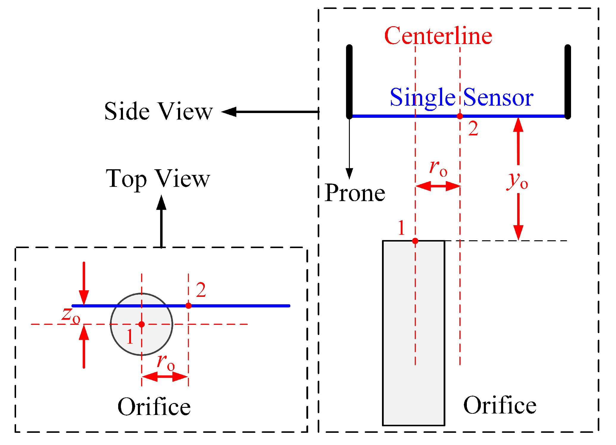
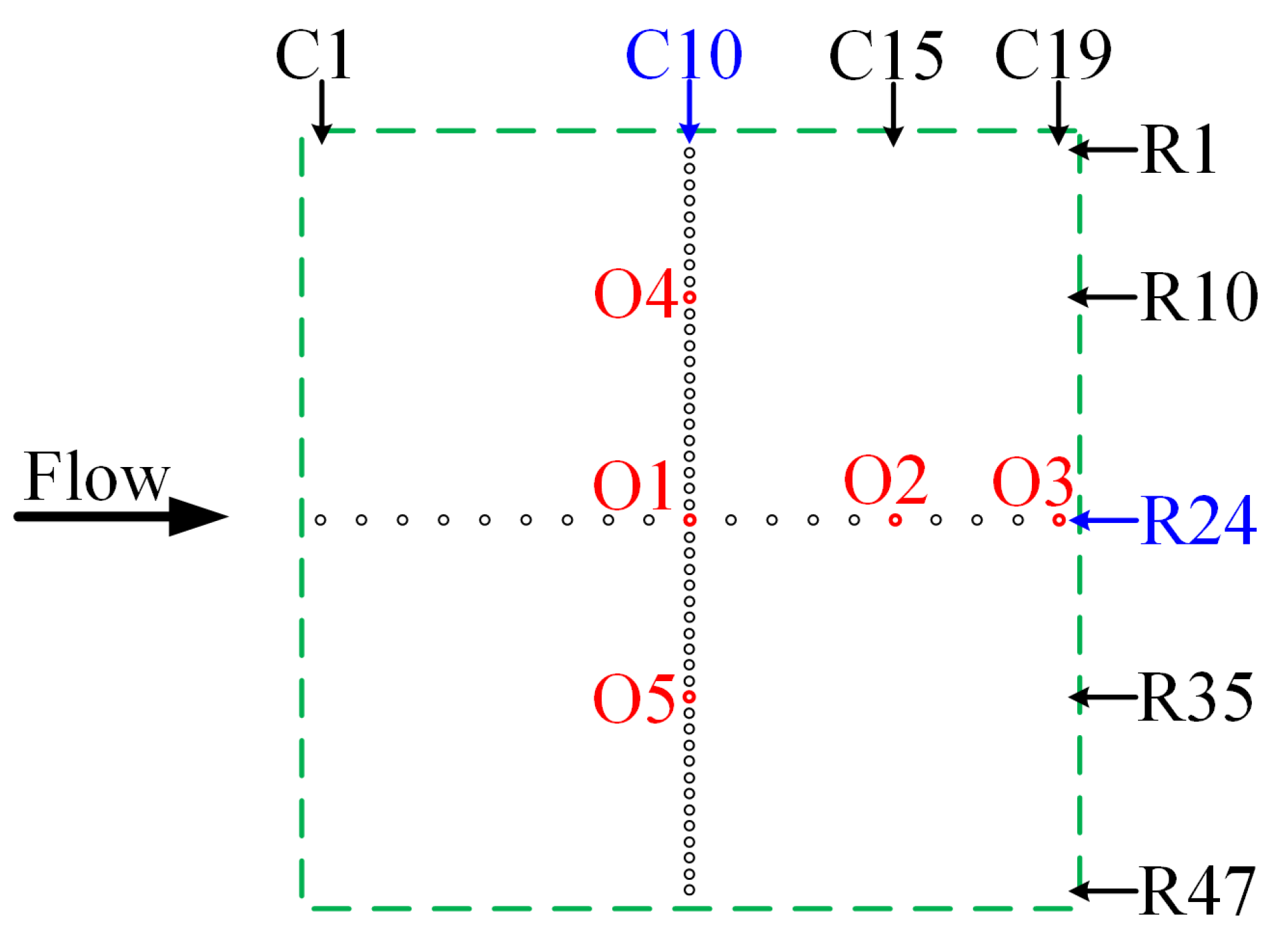
3.1. Measurement Method

The velocity characteristics of the distributed synthetic jets were measured by the IFA-300 constant-temperature anemometer with a model 1210-20 general-purpose probe in quiescent air. The IFA-300 constant temperature anemometer was calibrated using an AC-1 calibrator prior to measurement. The probe was calibrated below 19.6 m/s with 17 sampling points. The calibration curve was in the form of a quartic polynomial. The accuracy of the velocity measurement was estimated at ± 0.1 m/s below 2.7 m/s and ± 2 % of the measured value above 2.7 m/s. The velocity data were acquired at 10 kHz for 13.1072   s . The sample size was 131,072 for each record. In Section 2.5, it has been proven that the peak blowing velocity over one complete jet cycle is mainly determined by the frequency f in and voltage V in of the input signal, which constitute the operating conditions of the synthetic jet. For simplicity, the combination of f in and V in will be abbreviated as f in , V in hereafter. For example, f in = 10 Hz , V in = 60 V will be written as (10, 60).
Equation (11) illustrates the governing parameters of the peak blowing velocity u ˜ peak ; however, we cannot calculate u ˜ peak directly from Equation (11) because the peak-to-peak displacement Δ is difficult to acquire. With the hot-wire measurements, u ˜ peak is easy to obtain, and then the peak and the time-averaged blowing velocity u ¯ peak over N jet cycles can be determined by
u ¯ peak = 1 N i = 1 N u ˜ peak , i .
in which i denotes a complete jet cycle.
Figure 8 displays the definition of the hot-wire probe position in the measurements. Point 1 denotes the center of the orifice, and point 2 denotes the midpoint of the hot-wire (blue line in Figure 8). y o , z o and r o represent the normal distance, spanwise distance, and streamwise distance between point 1 and point 2. The diameter of the orifice was d o = 0.5 m m , whereas the length of the wire was 1.65 mm. In order to obtain an accurate measurement result, point 1 and point 2 should be located in one vertical centerline by moving the probe position. The movement of the probe was performed with a traversed system with a ± 0.02 mm positioning accuracy. A representative result at z o = 0 m m and y o / d o = 1 is shown in Figure 9. The peak and the time-averaged blowing velocity u ¯ peak achieved the maximum value at r o / d o = 0 .
The orifice array contained 893 orifices; accordingly, there were 893 jets in the distributed synthetic jet array. It would be very difficult to measure the injection velocity at each orifice. Velocity characteristic measurements were conducted at five selected orifices, which were O1(R24, C10), O2(R24, C15), O3(R24, C19), O4(R10, C10), and O5(R35, C10), as shown in Figure 10; moreover, they were performed along the orifices R24 and C10 to investigate the jet uniformity.

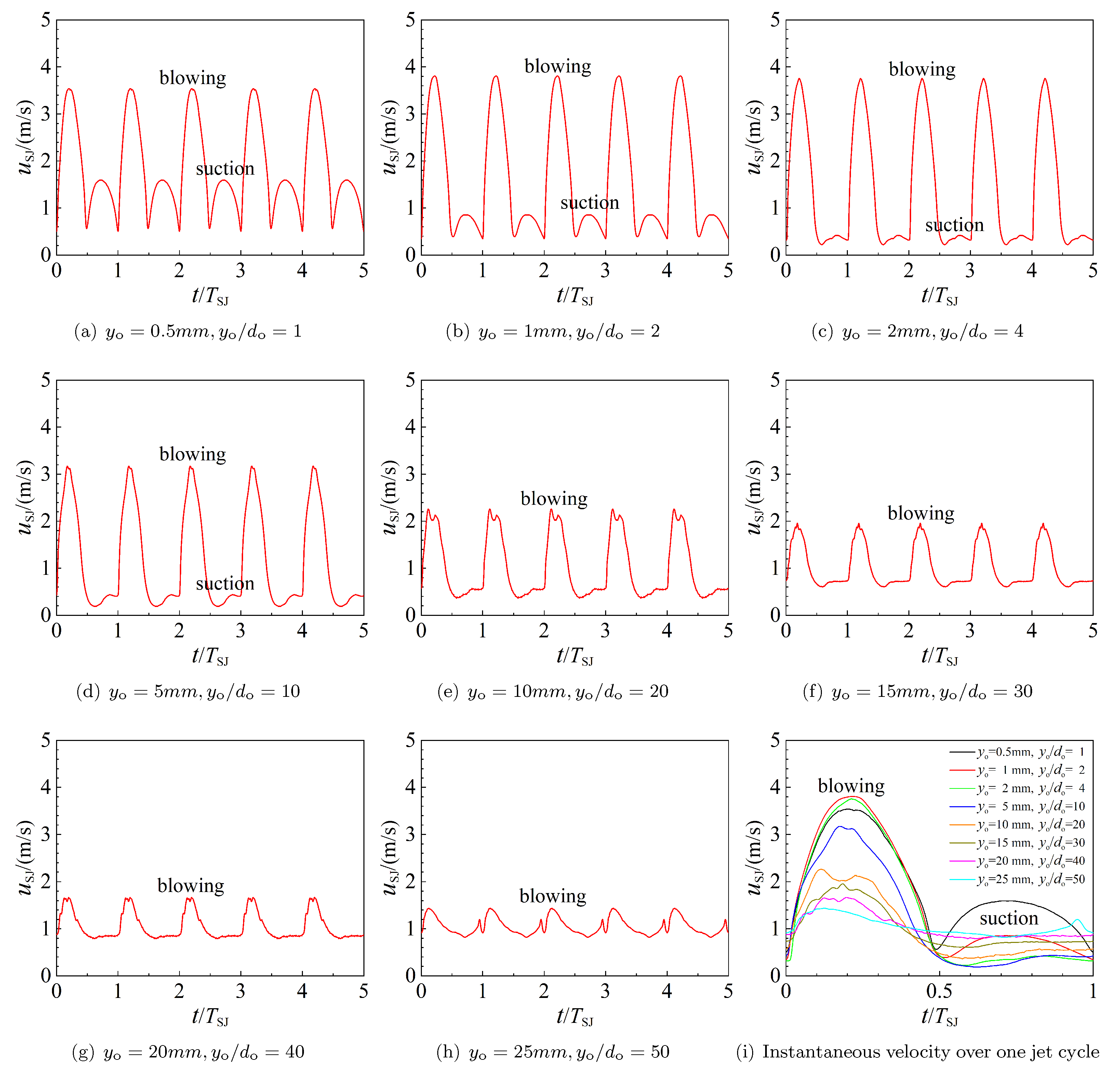
3.2. Instantaneous Velocity

Figure 11 displays the jet instantaneous velocities u SJ under the operating condition (5, 40) over five cycles. The jet showed a high and low peak in the injection velocity in one complete cycle. The high peak indicated blowing, whereas the low peak indicated suction. The blowing phase and suction phase showed disparate tendencies of variation with respect to y o . As y o increased, the peak blowing velocity u b , peak increased first and then decreased, whereas the peak suction velocity u s , peak decreased constantly. At y o / d o = 50 , the blowing phase still had a peak velocity of u b , peak = 1.5 m / s , whereas the suction phase almost vanished at y o / d o = 30 .
The mass of the fluid exiting and entering the cavity was constant in a complete jet cycle. In the blowing phase, the fluid exiting the cavity was mainly concentrated near the normal centerline of the orifices; thus, the blowing showed a higher velocity and reached further into the space. In the suction phase, the fluid entering the cavity through the orifices occurred along all directions; thus, the fluid closer to the orifices would be preferentially drawn into the cavity, whereas the fluid at a certain height above the orifices would not be drawn. Thus, the suction showed a lower velocity and persisted with a short distance into the space.

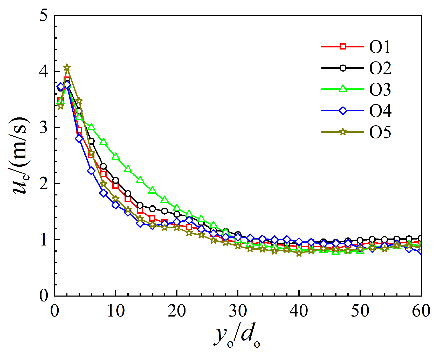
3.3. Centerline Velocity

With the hot-wire measurements, the centerline velocity can be achieved by
u c = u ¯ peak .
To obtain a complete centerline velocity variation, the measurements should be conducted at the centerline beginning from y o = 0   mm . However, this was challenging to perform due to the possible destruction of the hot-wire probe. The lowest position in the present measurements was 0.5 mm.
Figure 12 shows the time-averaged centerline velocity of the synthetic jet operating at (100, 33.6) at orifice O1∼O5. The maximum u c was observed at y o / d o = 2 , indicating that the velocity gradient was large in the range of 0 < y o / d o < 2 . In the near field, the centerline velocity showed a fast decay, and, in the far field at y o / d o > 30 , the velocity showed a slow decay, which indicated that the synthetic jet velocity tended to be stable beyond y o / d o = 30 .

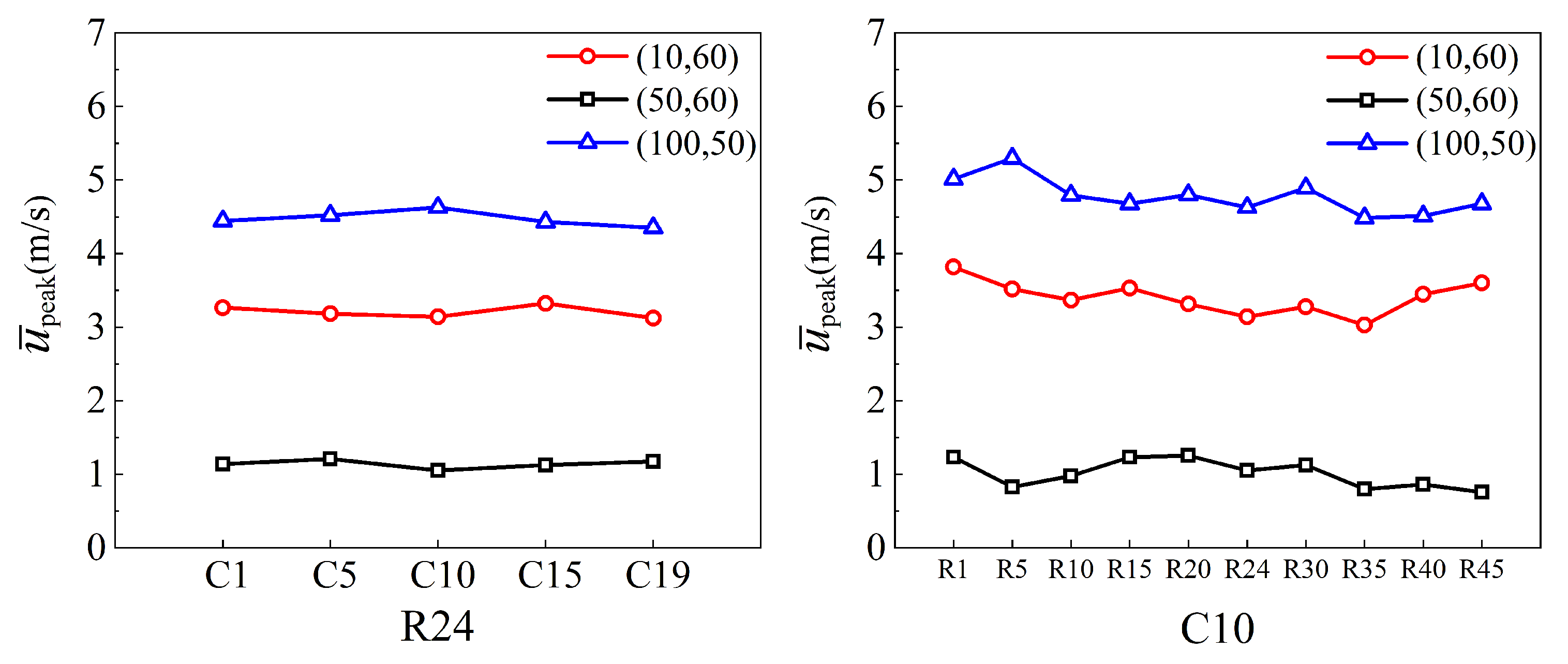
3.4. Synthetic Jet Uniformity

The measurement of synthetic jet uniformity was conducted along the orifices R24 and C10, as shown in Figure 10, under the operating conditions (10, 60), (50,60), and (100, 50). The specific positions were selected at the orifices (R24, C1/C5/C10/C15/C19) and (R1/R5/R10/R15/R20/R24/R30/R35/R40 /R45, C10).
Figure 13 shows the measurement results of the jet uniformity at y o / d o = 1 . Good uniformity appeared along R24, whereas poor uniformity appeared along C10. In the synthetic jet array, the spanwise space of two adjacent orifices was z = 2   mm , which was almost equivalent to the probe wire length of 1.65 mm, and the axis of the wire was in the spanwise direction as the measurements were conducted. Referring to Figure 8 and Figure 10 again, we could find that the measurements of the jet uniformity easily interfered with the jets ejected from the adjacent orifices. Considering this limitation, the results along R24 and C10 showed a good jet uniformity of the distributed synthetic jet array.

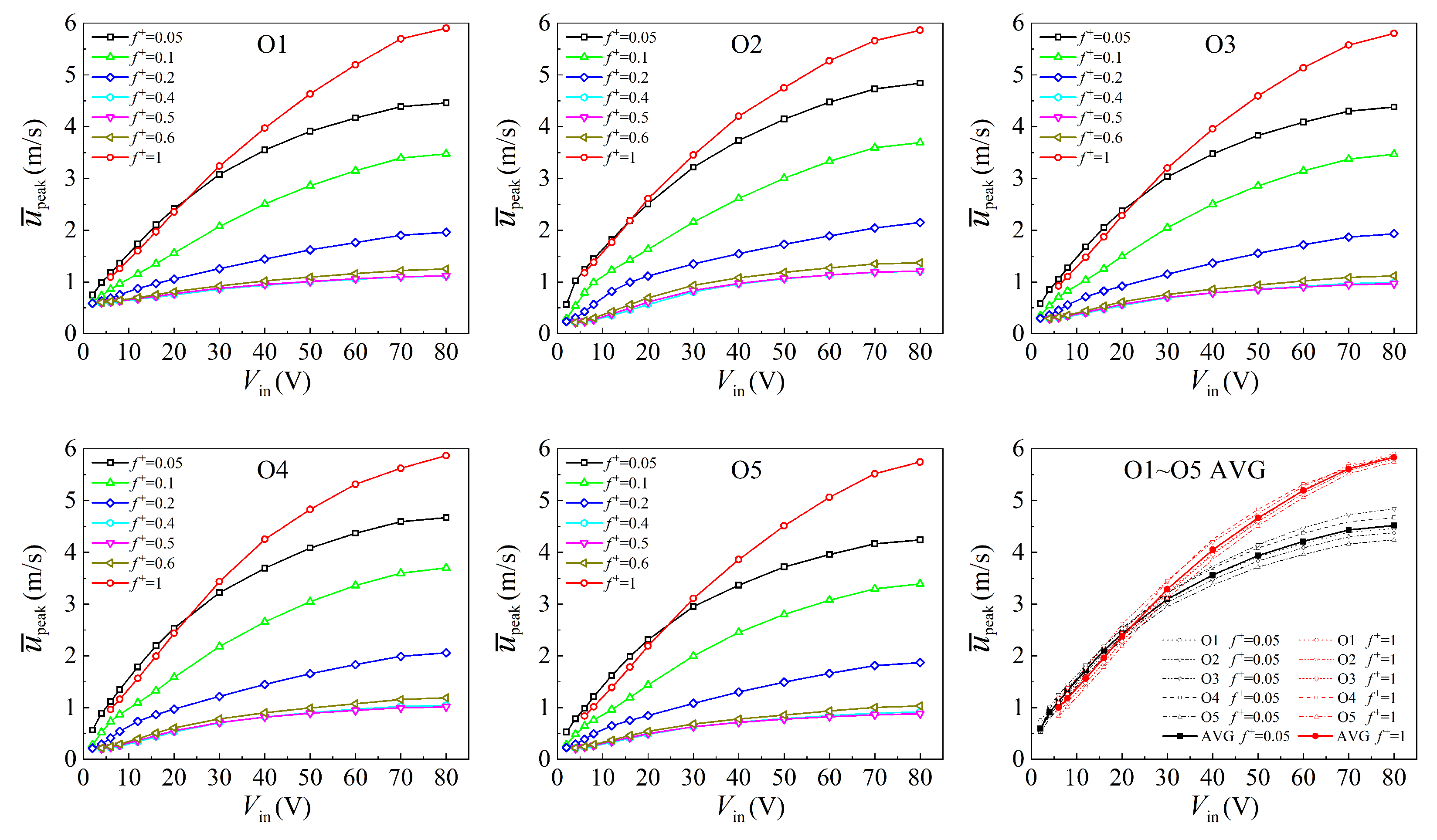
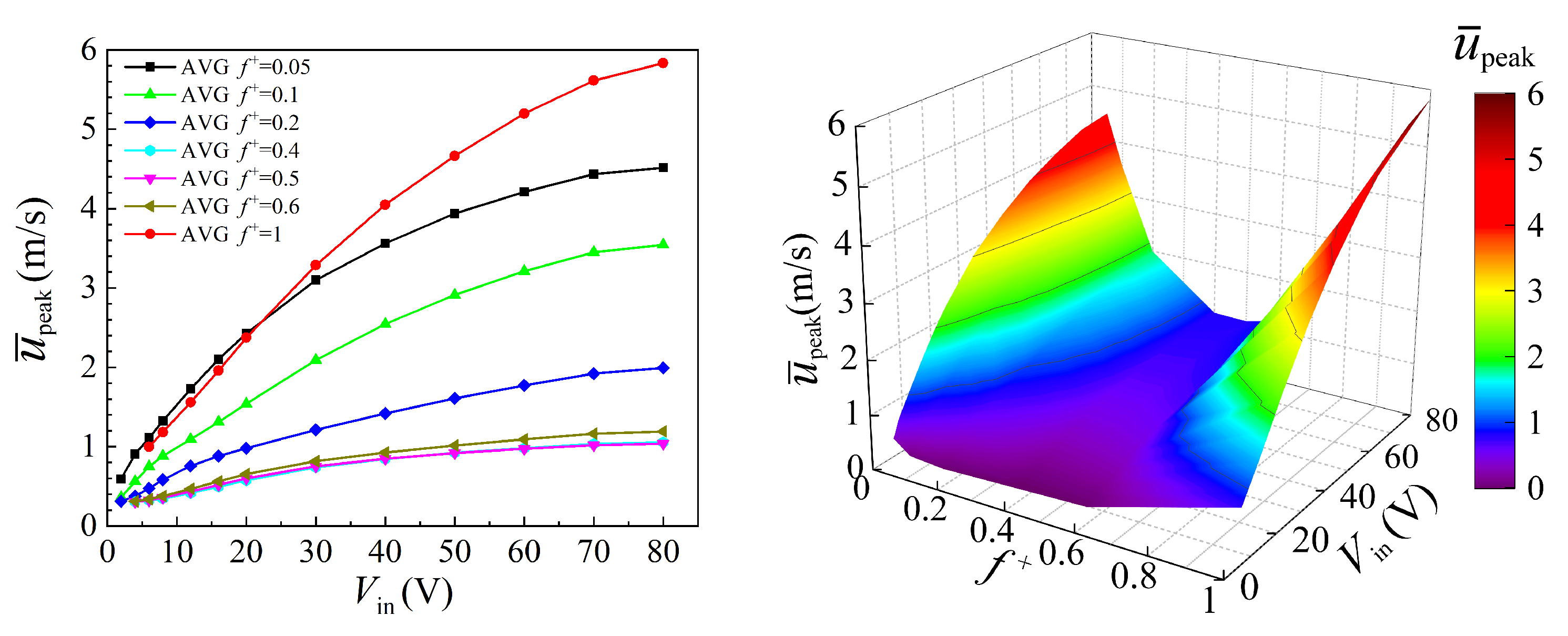
3.5. Parameter Space

The loudspeaker that we used was HIVI-K10, of which, the resonance frequency was 32 Hz . Figure 14 shows the actuator frequency response with pipes. It can be found that the frequency response of the synthetic jet actuator showed two peaks: one was 5 Hz and another was 100 Hz . The first corresponded to the actuator resonance and the second corresponded to the Helmholtz resonance. This result coincided with the study of Chiatto et al. [39]. Based on the frequency response result, the working frequency of the actuator could be normalized by the Helmholtz frequency [40], denoted as f h = 100 Hz , resulting in a non-dimensional working frequency, denoted as f + . The non-dimensional working frequency f + was expressed as:
f + = f in f h .
The jet velocity characteristics were measured under various operating conditions to obtain the parameter space of the synthetic jet. Figure 15 displays the parameter spaces at y o = 0.5   mm , y o / d o = 1 at orifices O1∼O5. Referring to the subfigure in the lower right corner, these parameter spaces exhibited a very high degree of consistency in both form and value.
The space-averaged parameter space is shown in Figure 16. The maximum value of u ¯ peak was 5.84 m/s; thus, the Reynolds number of the distributed synthetic jets was Re = ( d o u ¯ peak / π ) / ν = 61 , and the Strouhal number was S t = d o f in / ( u ¯ peak / π ) = 0.027 . It can be seen from the figure that the response of the synthetic jet to the input voltage V in was consistent. At every working frequency f + , a higher V in corresponded to a higher u ¯ peak . The response of the synthetic jet to the working frequency could be divided into three categories. In the range of f + = 0.05 0.4 , a lower f + corresponded to a higher u ¯ peak . At f + = 0.4 and 0.5, the u ¯ peak remained almost the same. In the range of f + = 0.5 1 , a lower f + corresponded to a lower u ¯ peak . This indicated that the frequency exerted a greater influence on the synthetic jet. The shape of the parameter space was very useful for investigating the influence of the synthetic jet frequency on the turbulent boundary layer. It also highlighted the importance of selecting the frequency with sufficient attention when using a synthetic jet in flow control. The measurement results of the distributed synthetic jets’ characteristics demonstrated that a design using multiple orifices corresponding to one diaphragm, proposed in this paper, was practicable.

4. Conclusions

In this study, an acoustic synthetic jet actuator with an oscillating diaphragm was assembled. The diaphragm was covered with a cylindrical cavity, whose volume varied as the diaphragm vibrated. By transferring the fluid from the cylindrical cavity to another constant-volume square cavity that was covered with a multiple-orifice plate, the implementation of multiple jets corresponding to one diaphragm was achieved.
It was found that the performance of the distributed synthetic jets was mainly determined by the operating parameters of the oscillating diaphragm, which were related to the frequency and voltage of the input signal to the actuator. The frequency exerted a greater influence on the synthetic jet than the voltage. The parameter space of the synthetic jets showed a canyon form, which made it easy to investigate the synthetic jet frequency effect on flow control.

Author Contributions

Conceptualization, L.L. and D.L. (Dong Li); methodology, L.L. and Z.Z.; software, Y.Y.; validation, L.L., Y.Y. and Z.Z.; formal analysis, L.L.; writing—original draft preparation, L.L.; writing—review and editing, Y.T. and D.L. (Dawei Liu); supervision, B.L.; funding acquisition, D.L. (Dong Li). All authors have read and agreed to the published version of the manuscript.

Funding

This research was funded by the project “Drag Reduction via Turbulent Boundary Layer Flow Control (DRAGY)” (Grant No. 690623). DRAGY is a China–EU Aeronautical Cooperation project, which is co-funded by the Ministry of Industry and Information Technology (MIIT), China, and the Directorate-General for Research and Innovation (DG RTD), European Commission.

Institutional Review Board Statement

Not applicable.

Informed Consent Statement

Not applicable.

Data Availability Statement

Not applicable.

Conflicts of Interest

The authors declare no conflict of interest.

References

  1. Glezer, A.; Amitay, M. Synthetic Jets. Annu. Rev. Fluid Mech. 2002, 34, 503–529. [Google Scholar] [CrossRef]
  2. Murugan, T.; Deyashi, M.; Dey, S.; Rana, S.C.; Chatterjee, P.K. Recent developments on synthetic jets. Def. Sci. J. 2016, 66, 489–498. [Google Scholar] [CrossRef]
  3. Smith, B.L.; Glezer, A. The formation and evolution of synthetic jets. Phys. Fluids 1998, 10, 2281–2297. [Google Scholar] [CrossRef]
  4. Holman, R.; Utturkar, Y.; Mittal, R.; Smith, B.L.; Cattafesta, L. Formation criterion for synthetic jets. AIAA J. 2005, 43, 2110–2116. [Google Scholar] [CrossRef] [Green Version]
  5. Garcillan, L.; Zhong, S.; Pokusevski, Z.; Wood, N. A PIV study of synthetic jets with different orifice shape and orientation. In Proceedings of the 2nd AIAA Flow Control Conference, Portland, OR, USA, 28 June–1 July 2004. AIAA 2004-2213. [Google Scholar]
  6. Crook, A.; Wood, N.J. Measurements and visualizations of synthetic jets. In Proceedings of the 39th Aerospace Sciences Meeting and Exhibit, Reno, NV, USA, 8–11 January 2001. AIAA 2001-0145. [Google Scholar]
  7. Tang, H.; Salunkhe, P.; Zheng, Y.; Du, J.; Wu, Y. On the use of synthetic jet actuator arrays for active flow separation control. Exp. Therm. Fluid Sci. 2014, 57, 1–10. [Google Scholar] [CrossRef]
  8. Chatlynne, E.; Rumigny, N.; Amitay, M.; Glezer, A. Virtual aero-shaping of a Clark-Y airfoil using synthetic jet actuators. In Proceedings of the 39th Aerospace Sciences Meeting and Exhibit, Reno, NV, USA, 8–11 January 2001. AIAA 2001-0732. [Google Scholar]
  9. Cheng, X.; Ma, C.; Liu, H.; Yang, C. Influence of synthetic jet on aerodynamic characteristics of blunt trailing edge wind turbine airfoil. J. Mech. Eng. 2016, 52, 148–156. [Google Scholar] [CrossRef]
  10. Wu, C.; Ahmed, N. Vectoring of a wall bounded planar jet using synthetic jet actuator. In Proceedings of the 31st AIAA Applied Aerodynamics Conference, San Diego, CA, USA, 24–27 June 2013. AIAA 2013-2515. [Google Scholar]
  11. Xia, Q.; Zhong, S. Liquids mixing enhanced by multiple synthetic jet pairs at low Reynolds numbers. Chem. Eng. Sci. 2013, 102, 10–23. [Google Scholar] [CrossRef]
  12. Zhang, J.; Gao, S.; Tan, X. Convective heat transfer on a flat plate subjected to normally synthetic jet and horizontally forced flow. Int. J. Heat Mass Transf. 2013, 57, 321–330. [Google Scholar] [CrossRef]
  13. Hafsteinsson, H.; Eriksson, L.E.; Cuppoletti, D.; Gutmark, E.; Prisell, E. Active suppression of supersonic jet noise using pulsating micro-jets. In Proceedings of the 50th AIAA Aerospace Sciences Meeting including the New Horizons Forum and Aerospace Exposition, Nashville, TN, USA, 9–12 January 2012. AIAA 2012-0246. [Google Scholar]
  14. Gilarranz, J.L.; Traub, L.W.; Rediniotis, O.K. A new class of synthetic jet actuators-part I: Design, fabrication and bench top characterization. J. Fluids Eng. 2005, 127, 367–376. [Google Scholar] [CrossRef]
  15. Chaudhari, M.; Verma, G.; Puranik, B.; Agrawal, A. Frequency response of a synthetic jet cavity. Exp. Therm. Fluid Sci. 2009, 33, 439–448. [Google Scholar] [CrossRef]
  16. Smyk, E.; Gil, P.; Gałek, R.; Przeszłowski, Ł. Acoustic and flow aspects of novel synthetic jet actuator. Actuators 2020, 9, 100. [Google Scholar] [CrossRef]
  17. Gil, P.; Wilk, J. Experimental investigations of different loudspeakers applied as synthetic jet actuators. Actuators 2021, 10, 224. [Google Scholar] [CrossRef]
  18. Bailo, K.C.; Brei, D.E.; Calkins, F.T. Investigation of PVdF active diaphragms for synthetic jets. In Proceedings of the SPIE’s 7th Annual International Symposium on Smart Structures and Materials, Newport Beach, CA, USA, 6 March 2000. [Google Scholar]
  19. Liang, Y.; Kuga, Y.; Taya, M. Design of membrane actuator based on ferromagnetic shape memory alloy composite for synthetic jet applications. Sens. Actuat. A-Phys. 2006, 125, 512–518. [Google Scholar] [CrossRef]
  20. Grossman, K.R.; Cybyk, B.Z.; Rigling, M.C.; VanWie, D.M. Characterization of sparkjet actuators for flow control. In Proceedings of the 42nd AIAA Aerospace Sciences Meeting and Exhibit, Reno, NV, USA, 5–8 January 2004. AIAA 2004-89. [Google Scholar]
  21. Caruana, D.; Barricau, P.; Hardy, P.; Cambronne, J.P.; Belinger, A. The “plasma synthetic jet” actuator. Aero-thermodynamic characterization and first flow control applications. In Proceedings of the 47th AIAA Aerospace Sciences Meeting Including The New Horizons Forum and Aerospace Exposition, Orlando, FL, USA, 5–8 January 2009. AIAA 2009-1307. [Google Scholar]
  22. Zhang, Z.; Li, D. Characteristics of a synthetic jet actuator and its application on control of flow over a backward facing step. J. Mech. Eng. 2018, 54, 224–232. [Google Scholar] [CrossRef]
  23. Zhong, S.; Jabbal, M.; Tang, H.; Garcillan, L.; Guo, F.; Wood, N.; Warsop, C. Towards the design of synthetic-jet actuators for full-scale flight conditions—Part 1: The fluid mechanics of synthetic-jet actuators. Flow Turbul. Combust. 2007, 78, 283–307. [Google Scholar] [CrossRef]
  24. Tang, H.; Zhong, S.; Jabbal, M.; Garcillan, L.; Guo, F.; Wood, N.; Warsop, C. Towards the design of synthetic-jet actuators for full-scale flight conditions—Part 2: Low-dimensional performance prediction models and actuator design method. Flow Turbul. Combust. 2007, 78, 309–329. [Google Scholar] [CrossRef]
  25. Tang, H.; Zhong, S. Incombressible Flow Model of Synthetic Jet Actuators. AIAA J. 2006, 44, 908–912. [Google Scholar] [CrossRef]
  26. Gil, P.; Strzelczyk, P. Performance and efficiency of loudspeaker driven synthetic jet actuator. Exp. Therm. Fluid Sci. 2016, 76, 163–174. [Google Scholar] [CrossRef]
  27. Shuster, J.M.; Smith, D.R. A study of the formation and scaling of a synthetic jet. In Proceedings of the 42nd AIAA Aerospace Sciences Meeting and Exhibit, Reno, NV, USA, 5–8 January 2004. AIAA 2004-90. [Google Scholar]
  28. Luca, L.; Girfoglio, M.; Coppola, G. Modeling and experimental validation of the frequency response of synthetic jet actuators. AIAA J. 2014, 52, 1733–1748. [Google Scholar] [CrossRef]
  29. Mark, A.F.; Philippe, L.; Pierre, E.S. Influence of cavity shape on synthetic jet performance. Sens. Actuat. A-Phys. 2015, 223, 1–10. [Google Scholar]
  30. Zhao, Z.; Ding, J.; Shi, S.; Kaufmann, R.; Ganapathisubramani, B. Volumetric flow characterisation of a rectangular orifice impinging synthetic jet with single-camera light-field PIV. Exp. Therm. Fluid Sci. 2021, 123, 110327. [Google Scholar] [CrossRef]
  31. Palumbo, A.; Luca, L. Experimental and CFD characterization of a double-orifice synthetic jet actuator for flow control. Actuators 2021, 10, 326. [Google Scholar] [CrossRef]
  32. Chaudhari, M.; Puranik, B.; Agrawal, A. Multiple orifice synthetic jet for improvement in impingement heat transfer. Int. J. Heat Mass Transf. 2011, 54, 2056–2065. [Google Scholar] [CrossRef]
  33. Mangate, L.; Yadav, H.; Agrawal, A.; Chaudhari, M. Experimental investigation on thermal and flow characteristics of synthetic jet with multiple-orifice of different shapes. Int. J. Therm. Sci. 2019, 140, 344–357. [Google Scholar] [CrossRef]
  34. Gil, P. Experimental investigation on heat transfer enhancement of air-cooled heat sink using multiple synthetic jets. Int. J. Therm. Sci. 2021, 166, 106949. [Google Scholar] [CrossRef]
  35. Gil, P.; Smyk, E.; Gałek, R.; Przeszłowski, Ł. Thermal, flow and acoustic characteristics of the heat sink integrated inside the synthetic jet actuator cavity. Int. J. Therm. Sci. 2021, 170, 107171. [Google Scholar] [CrossRef]
  36. Kline, S.J.; Reynolds, W.C.; Schraub, F.A.; Runstadler, P.W. The structure of turbulent boundary layers. J. Fluid Mech. 1967, 30, 741–773. [Google Scholar] [CrossRef] [Green Version]
  37. Kim, H.T.; Kline, S.J.; Reynolds, W.C. The production of turbulence near a smooth wall in a turbulent boundary layer. J. Fluid Mech. 1971, 50, 133–160. [Google Scholar] [CrossRef]
  38. Smith, C.R.; Metzler, S.P. The characteristics of low-speed streaks in the near-wall region of a turbulent boundary layer. J. Fluid Mech. 1983, 129, 27–54. [Google Scholar] [CrossRef]
  39. Chiatto, M.; Palumbo, A.; Luca, L. Design approach to predict synthetic jet formation and resonance amplifications. Exp. Therm. Fluid Sci. 2019, 107, 79–87. [Google Scholar] [CrossRef]
  40. Zong, H.; Chiatto, M.; Kotsonis, M.; Luca, L. Plasma synthetic jet actuators for active flow control. Actuators 2018, 7, 77. [Google Scholar] [CrossRef]
Figure 1. Photographs of the actuator components and operating procedure of the synthetic jet actuator.
Actuators 11 00300 g001
Figure 2. Function relationship between V PA and V SG at G PA = 25 .
Actuators 11 00300 g002
Figure 3. Schematic of the diaphragm and the cylindrical cavity.
Actuators 11 00300 g003
Figure 4. Schematic of the implementation of multiple orifices corresponding to one diaphragm.
Actuators 11 00300 g004
Figure 5. Square cavity of the synthetic jet array: (a) schematic (side view); (b) cavity installed beneath the wind tunnel floor.
Actuators 11 00300 g005
Figure 6. Orifice array: photograph and schematic (top view).
Actuators 11 00300 g006
Figure 7. Volume variation of the cylindrical cavity: (a) input signal and schematic of the movement of oscillating diaphragm; (b) volume variation equivalence of the cylindrical cavity.
Actuators 11 00300 g007
Figure 8. Definition of hot-wire probe position in the measurements of synthetic jet velocity characteristics. Point 1 refers to the center of the orifice, and point 2 refers to the midpoint of the hot-wire.
Actuators 11 00300 g008
Figure 9. Representative measurement result of the peak and time-averaged blowing velocity of the synthetic jet. The measurement was conducted at z o = 0   mm and y o / d o = 1 with varying r o .
Actuators 11 00300 g009
Figure 10. Orifices at which velocity characteristics of the synthetic jets were measured. Positions of the orifices were O1(R24, C10), O2(R24, C15), O3(R24, C19), O4(R10, C10), and O5(R35, C10).
Actuators 11 00300 g010
Figure 11. Jet instantaneous velocity at orifice O1.
Actuators 11 00300 g011
Figure 12. Jet centerline velocity at orifice O1∼O5 with the synthetic jet operating at (100, 33.6).
Actuators 11 00300 g012
Figure 13. Synthetic jet uniformity along the orifices R24 and C10 at y o / d o = 1 .
Actuators 11 00300 g013
Figure 14. Frequency response of the synthetic jet actuator with pipes.
Actuators 11 00300 g014
Figure 15. Parameter spaces of synthetic jets at orifices O1∼O5. The normal distance to the injection plane was y o = 0.5   mm , y o / d o = 1 .
Actuators 11 00300 g015
Figure 16. Space-averaged parameter space of synthetic jet at y o = 0.5   mm , y o / d o = 1 .
Actuators 11 00300 g016
Table 1. Orifice array geometry dimensions.
zl d o h o
2.0 mm 5.0 mm 0.5 mm 5.0 mm
81 δ ν 202 δ ν --
Publisher’s Note: MDPI stays neutral with regard to jurisdictional claims in published maps and institutional affiliations.

