Abstract
Superconducting techniques are applied to a superconducting magnetic suspension system. A superconducting coil, copper coils, a magnetically suspended object, a photo sensor, a PID controller, and power amplifiers are the main components of the suspension system. A persistent current in the superconducting coil and a control current in the copper coils are used for suspending the object and controlling the object, respectively. This paper discusses a large gap trial for the suspension system, and the static and dynamic characteristics of the suspension system are studied. As a result, it is found that the magnetically suspended object continues to be suspended at a distance of 82 mm for more than 60 s. Since a superconducting persistent current has a maximum limit for the suspension system, a persistent current of 50 A is adopted. The details of the superconducting persistent current are studied for the performance of the suspension system. There are few reports about such a suspension system with a large gap of more than 80 mm using a superconducting persistent current.
1. Introduction
The magnetic suspension technique is very attractive because it is mechanical contact-free [1,2,3]. In general, the magnetic suspension technique uses electromagnets (EMs) for controlling the positions of the suspended objects. A lot of electric power and energy are necessary for suspending an object in the case of suspension systems with many EMs. Supposing wind tunnel test equipment is set up with an airplane model, the airplane model (or another model) is supported mechanically, to keep it in the center of the wind tunnel. However, the mechanical support for the airplane model isn’t necessary to accurate measurement, because the mechanical support disturbs air flow around the airplane model (or other model). Therefore, in order to perform an accurate measurement of air flow, the magnetic suspension technique is very attractive for wind tunnel test equipment [4,5]. For realizing a larger distance between EMs and the airplane model (the suspended object), it is necessary for suspension systems to generate much larger electromagnetic forces. Therefore, application of electromagnetic forces using permanent magnets (PMs) is tried to reduce electric power [6,7]. However, in order to generate larger electromagnetic forces using PMs, there is a technical limit for making PMs with much larger dimensions.
On the other hand, the superconducting technique is useful for various kind of levitation or suspension systems [8,9,10,11]. In particular, superconducting coils are suitable for suspension systems [12]. In [12], a persistent current in the superconducting coil and a control current in the copper coil are used for suspending the object and controlling the object, respectively. In this case, there is no electric power loss in the superconducting coil because there is no electric resistance of the superconducting coil.
In this paper, basic studies on the mutual interaction between superconducting coils and copper coils are performed. A suspended object with a large distance (gap) of 82 mm is realized. Moreover, the dynamic characteristics of the suspension system are studied.
2. Superconducting Magnetic Suspension System
2.1. Structure
A schematic illustration of a suspension system using a persistent current in an upper superconducting coil is shown in Figure 1. An upper superconducting coil, upper and lower copper coils, a suspended object, a photo sensor, an analog PID controller and some power amplifiers are the main components of the system. The superconducting coil is a BiSCCO material (Sumitomo Electric) and the critical current of the superconducting coil (100 turns) is 160 A (at 77 K). The dimensions of the superconducting coil are 103.4 mm in outer diameter, 60 mm in inner diameter and 10 mm in width. The persistent current is produced in the superconducting coil. The dimensions of the copper coil (0.3 mm × 500 turns) are 96 mm in outer diameter, 60 mm in inner diameter and 25 mm in thickness. The superconducting coil and two copper coils are set in an upper container and the two copper coils are also set in lower container, as shown in Figure 1. During the experiments, both the superconducting coil and the copper coils are cooled in liquid nitrogen inside the container, and are used for suspending the object and controlling the object, respectively. The suspended object (30 × 40 mm, 96.3 g), has a PM (NdFeB, 20 × 30 mm, 70.5 g) inside it. A photo sensor is used for detecting the displacement of the suspended plastic object, as shown in Figure 1.
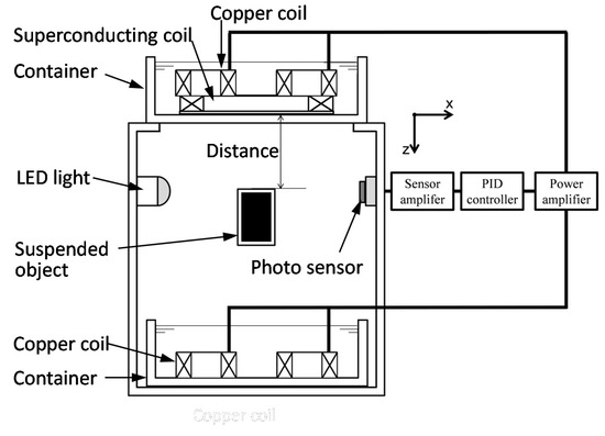
Figure 1.
Schematic illustration of suspension system using persistent current in superconducting coil.
2.2. Superconducting Coil and Persistent Current
Figure 2 shows a photo of the superconducting coil for the persistent current. In the figure, the yellow part is the superconducting coil. The dimensions of the superconducting coil are 103.4 mm in outer diameter, 60 mm in inner diameter and 10 mm in width. Using the superconducting coil, the persistent current mode test is performed.
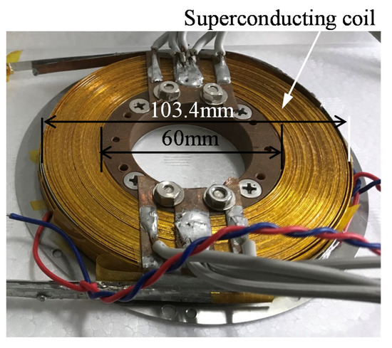
Figure 2.
Photo of superconducting coil for persistent current.
The electric circuit for the persistent current mode is shown in Figure 3. A superconducting coil, a persistent current switch (SW) and a DC power supply are the main components of the electric circuit [13]. After the persistent current SW is turned off, the DC power supply applies a constant current to the superconducting coil as shown in Figure 3a. After the SW is turned on, the DC power supply applies constant current to the superconducting coil and the SW as shown in Figure 3b. Moreover, after the DC power supply is turned off, the superconducting coil continues to keep the constant current (persistent current) in the superconducting coil as shown in Figure 3c. In this way, the persistent current in the superconducting coil is generated.
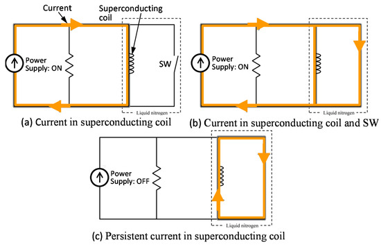
Figure 3.
Electric circuit for persistent current mode.
The relationships between the persistent current and time for the various initial currents of 30, 40, 50 and 60 A in the time range from 0 to 5 min are shown in Figure 4. In the experiment, the persistent currents are measured using a Hall sensor. Each persistent current for 30, 40, 50 and 60 A keeps constant in the time range from 0 to 5 min, and there is no current decrease in the same time range. The persistent current, for at least 5 min, is sufficient to perform some experiments. Thus, the persistent currents from 30 A to 60 A are useful for the suspension system.
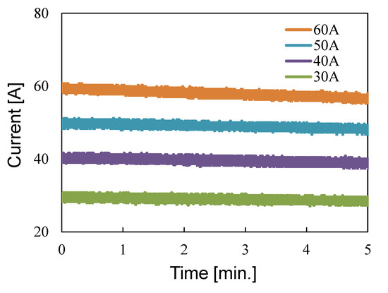
Figure 4.
Relationship between persistent current and time for various initial currents of 30, 40, 50 and 60A.
2.3. Suspension Force by Superconducting Coil
Figure 5 shows an experimental setup for measuring the suspension force between the superconducting coil and the suspended object. The measurement is performed using a load cell attached to a Z stage. Since the Z stage moves in the vertical direction, the distance between the superconducting coil and the suspended object can be adjusted.
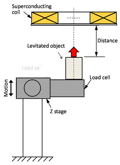
Figure 5.
Experimental setup for measuring attractive forces between a superconducting coil and the suspended object.
Figure 6 shows the relationship between the suspension force and the distance for the various applied currents of 40, 50 and 60 A. The measurement is performed using the experimental setup in Figure 5. Each suspension force decreases with increasing distance. The suspension force becomes larger as the applied current increases. In the figure, a force of 0 N means that the weight of the object is equal to the suspension force. That is, in the cases of 40 A, 50 A and 60 A, the equivalent distances are 76 mm, 82 mm and 88.5 mm, respectively. Hereafter, a persistent current of 50 A (82 mm) is adopted in the experiments.
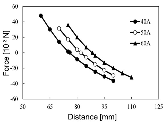
Figure 6.
Relationship between suspension force and distance from a superconducting coil to the suspended object.
2.4. Mutual Interaction between Superconducting Coil and Copper Coils
Figure 7 shows the experimental setup for studying the mutual interaction between the superconducting coil and the copper coils. In Figure 7a, one copper coil, a superconducting coil and a Hall sensor are set in liquid nitrogen. The Hall sensor is beside the copper coils to measure the magnetic flux density. In Figure 7b, two copper coils, a superconducting coil and a Hall sensor are set in liquid nitrogen, where the two copper coils are on the superconducting coil to evaluate the mutual interaction between the superconducting coil and the copper coils. In the experiment, using the setups in Figure 7, magnetic flux densities in the case of Figure 7a,b are measured for various persistent currents from 5 A to 10 A.
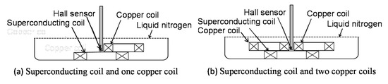
Figure 7.
Experimental setup for mutual interaction between superconducting coil and copper coils.
Figure 8 shows the relationship between the magnetic flux density and the applied current to one copper coil for the various persistent currents of (a) 5 A, (b) 8 A, (c) 9 A and (d) 10 A. In the figure, the white circle and the black circle are magnetic flux density without the superconducting coil and that with superconducting coil, respectively. In the case of 5 A (Figure 8a), the magnetic flux density without the superconducting coil (white circles) and the magnetic flux density with the superconducting coil (black circles) are plotted in the same area. The same phenomenon in Figure 8b–d is observed as in Figure 8a. This means that there is no mutual interaction between a superconducting coil and one copper coil.
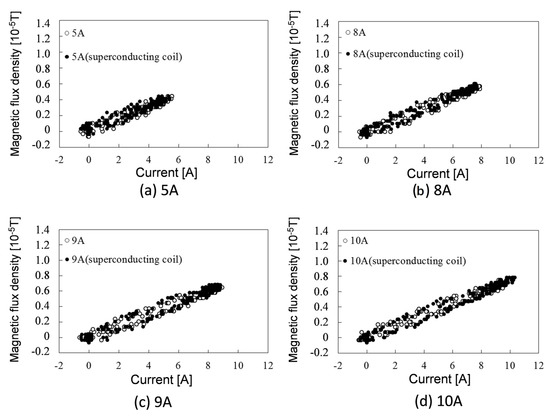
Figure 8.
Relationship between magnetic flux density and applied current to right copper coil for various persistent currents of (a) 5A, (b) 8A, (c) 9A and (d) 10A.
Figure 9 shows the relationship between the magnetic flux density and the applied current to two copper coils for the various persistent currents of (a) 5 A, (b) 8 A, (c) 9 A and (d) 10 A. In the figure, the white circle and the black circle are the magnetic flux densities without the superconducting coil and that with the superconducting coil, respectively. In the case of 5 A (Figure 9a), the magnetic flux density without the superconducting coil (white circles) and the magnetic flux density with the superconducting coil (black circles) are plotted in a slightly different area. This means that the control current is a little affected by the persistent current. However, the maximum difference at current of 10 A in Figure 9d is 0.4 × 10⁻⁶ T, which is not so large for a control current. Thus, the experimental setup shown in Figure 7b is adopted for the suspension system as shown in Figure 1.
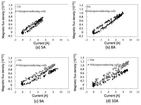
Figure 9.
Relationship between magnetic flux density and applied current to two copper coils for various persistent currents of (a) 5A, (b) 8A, (c) 9A and (d) 10A.
3. Magnetic Suspension Experiments and Discussions
3.1. Control System
Figure 10 shows the schematic illustration of the control force applied to the suspended object. As shown in Figure 10, the superconducting coil and two copper coils are set in the upper container of the system, and two copper coils are set in the lower container. The superconducting coil and copper coils are in liquid nitrogen during the experiments. In the experiments hereafter, the superconducting coil is used for suspending the weight of object and the copper coils are used for controlling the displacement of suspended object. These four copper coils are connected in a series. Thus, in the case that the polarities of the upper coils are S, repulsive forces are produced as shown in Figure 10. In the case that polarities of lower coils are S, attractive forces are produced. The repulsive force and attractive force move the suspended object downwards.
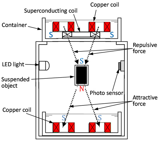
Figure 10.
Schematic illustration of control force applied to suspended object.
Figure 11 shows the relationship between the attractive force and the applied current to the copper coils. In the experiment, the four copper coils are connected in a series. Then, the attractive force to the object is produced in the vertical direction. As shown in Figure 11, the relationship between the attractive force and the applied current is almost linear, which is useful for controlling the suspended object.
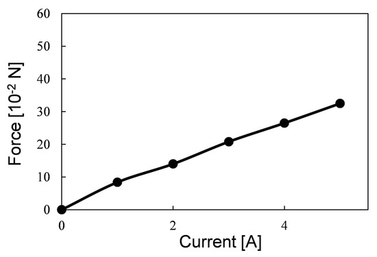
Figure 11.
Relationship between attractive force and applied current to copper coils.
Figure 12 shows the relationship between the sensor output voltage Vout and the distance between the superconducting coil and the suspended object. Although the relationship in the distance range from 80 mm to 84 mm is not linear, the relationship near 82 mm is almost linear. Thus, the slope (corresponding to the sensor gain) at a distance of 82 mm is applied to the suspension system.
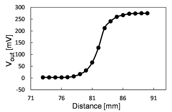
Figure 12.
Relationship between output voltage and distance between superconducting coil and suspended object.
3.2. Suspension Experiments
The photo of the magnetically suspended object in the center, using the persistent current of 50 A, is shown in Figure 13. The object is magnetically suspended at a distance of 82 mm. The distance of 82 mm means the distance from the superconducting coil’s bottom surface to the suspended object’s top surface. Thus, the distance from the container’s bottom surface to the suspended object’s top surface is 76 mm. It is seen that there is a shadow from the suspended object on the photo sensor as shown in Figure 13. In the experiments hereafter, the conditions of the suspended object using the DC power current and a persistent current are studied.
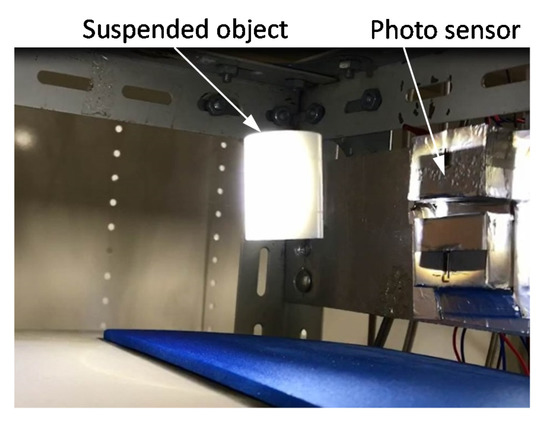
Figure 13.
Photo of magnetically suspended object in the center.
Figure 14 shows the experimental results for the magnetically suspended object, representing (a) the distance from the superconducting coil’s bottom surface to the suspended object and (b) the control current to the copper coils. In the experiment, the DC power-supplied current to the superconducting coil is 50 A. Figure 14a shows that the object succeeds at being suspended at a distance of 82 mm and continues to keep the suspension for more than 60 s. During the suspension, the displacement is small and less than 0.5 mm. Figure 14b shows that the amplitude of the control current is less than 2 A. Figure 15 shows the experimental results for the magnetically suspended object, representing (a) the distance from superconducting coil’s bottom surface to the suspended object and (b) the control current to the copper coils. In the experiment, a persistent current of 50 A is applied to the superconducting coil. In the same manner as Figure 14a, the object is suspended at a distance of 82 mm for more than 60 s. During the suspension, the displacement is small and less than 0.5 mm. Figure 15b shows that the amplitude of the control current is less than 3 A, which is a little larger than the control current in Figure 14b. As a result of experiment in Figure 15, it is found that the suspension system works well.
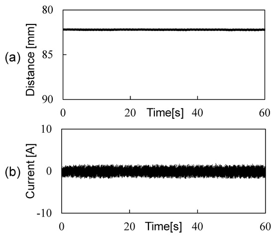
Figure 14.
Relationships between (a) distance and time and between (b) current and time in the case of DC power supplied current.
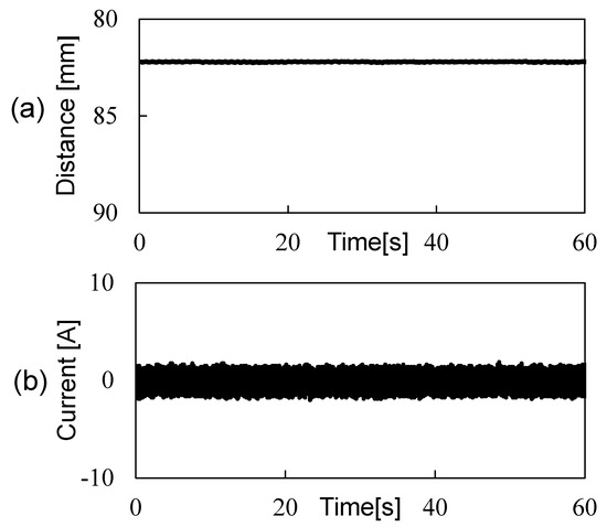
Figure 15.
Relationships between (a) distance and time and between (b) current and time in the case of persistent current.
4. Summary
The suspension system using a persistent current of 50 A is developed. The static characteristics of the system are summarized as follows:
- (a)
- The persistent currents from 30 A to 60 A are useful for the suspension system;
- (b)
- The mutual interaction between the superconducting coil and the copper coils is not so large for the control current;
- (c)
- The slope (corresponding to the sensor gain), at a distance of 82 mm, is applicable to the suspension system.
The dynamic characteristics of the system are summarized as follows:
- (d)
- The persistent current of 50 A is applied to the superconducting coil.
- (e)
- The experimental results show that the object succeeds at being suspended at a distance of 82 mm and continues to keep the suspension for more than 60 s.
- (f)
- During the suspension, the displacement is small at less than 0.5 mm, and the amplitude of the control current is less than 3 A.
As a result of these experiments, it is found that the suspension system works well and seems to be very promising for some applications, such a wind tunnel test equipment.
Author Contributions
Administration and investigation, M.K.; Experiment and measurement, S.I., K.N., K.-i.A. All authors have read and agreed to the published version of the manuscript.
Funding
This study is supported by the Iwatani Naoji Foundation.
Institutional Review Board Statement
Not applicable.
Informed Consent Statement
Not applicable.
Data Availability Statement
The data reported in this manuscript is accessible based on reasonable requests to the corresponding author.
Conflicts of Interest
The authors declare no conflict of interest.
References
- Mizuno, T.; Sekine, D.; Ishino, Y.; Takasaki, M. Proposal of Force Measurement Using Series Magnetic Suspension. In Proceedings of the 5th Annual Dynamic Systems and Control Conference Joint with 11th Motion and Vibration Conference, Fort Lauderdale, FL, USA, 17–19 October 2012; pp. 55–60. [Google Scholar]
- Kawamura, Y.; Mizota, T. Wind Tunnel Experiment of Bluff Body Aerodynamic Models Using a New Type of Magnetic Suspension and Balance System. J. Fluids Eng. 2013, 135, 101401. [Google Scholar] [CrossRef]
- Gonzalez-Ballestero, C.; Aspelmeyer, M.; Novotny, L.; Quidant, R.; Romero-Isart, O. Levitodynamics: Levitation and control of microscopic objects in vacuum. Science 2021, 374, 1–17. [Google Scholar] [CrossRef] [PubMed]
- Chrisinger, J.E.; Tilton, E.L.; Parkin, W.J.; Coffin, J.B.; Covert, E.E. Magnetic Suspension and Balance System for Wind Tunnel Application. J. R. Aeronaut. Soc. 1963, 635, 717–724. [Google Scholar] [CrossRef]
- Richmond, P.; Boyden, C.; Britcher, P.; Ping, T. Status of Wind Tunnel Magnetic Suspension Research. SAE Trans. 1985, 6, 769–777. [Google Scholar]
- Kawamura, Y.; Takenaga, T.; Oh, J.-B.; Takahashi, T.; Kwon, C.-K.; Mizota, T. Development of a low electric power 40 cm class magnetic suspension and balance system. J. Wind Eng. 2004, 1, 117–127. [Google Scholar] [CrossRef][Green Version]
- Sawada, H.; Kunimatsu, T. Development of a 60cm Magnetic Suspension System. J. Jpn. Soc. Aeronaut. Space Sci. 2002, 580, 188–195. [Google Scholar]
- Hull, J.R.; Mulcahy TM Uherka, K.L.; Abboud, R.G. Low rotational drag in high-temperature superconducting bearings. IEEE Trans. Appl. Supercond. 1995, 2, 626–629. [Google Scholar] [CrossRef]
- Komori, M.; Kobayashi, H.; Kumamoto, M. Hybrid high Tc superconducting magnetic bearing (SMB) system with no bias currents. In Proceedings of the 6th International Symposium on Magnetic Bearings, Cambridge, MA, USA, 5–7 August 1998; pp. 214–223. [Google Scholar]
- Maruo, E.; Komori, M. A trial of superconducting magnetic levitation (SML) with superconducting coil. J. Jpn. Soc. Appl. Electromagn. Mech. 2011, 3, 79–82. [Google Scholar]
- Nakaya BKomori, M.; Asami, K.; Sakai, N. Dynamic Characteristics of Magnetically Levitated Conveyer Using High Tc SMB. IEEE Trans. Appl. Supercond. 2013, 3, 1–4. [Google Scholar]
- Takase, S.; Komori, M.; Nemoto, K.; Asami, K.; Sakai, N. Basic study on magnetic levitation system using superconducting coil. JSME Mech. Eng. J. 2015, 3, 1–8. [Google Scholar] [CrossRef][Green Version]
- Igarashi, M.; Nemoto, K.; Okutomi, T.; Hirano, S.; Kuwano, K.; Kusada, S.; Terai, M.; Kuriyama, T.; Tosaka, T.; Tasaki, K.; et al. Persistent current HTS magnet for Maglev applications. Teion-Kougaku 2004, 12, 651–659. [Google Scholar] [CrossRef][Green Version]


Publisher’s Note: MDPI stays neutral with regard to jurisdictional claims in published maps and institutional affiliations. |
© 2022 by the authors. Licensee MDPI, Basel, Switzerland. This article is an open access article distributed under the terms and conditions of the Creative Commons Attribution (CC BY) license (https://creativecommons.org/licenses/by/4.0/).