Article

Electroelastic Coupled-Wave Scattering and Dynamic Stress Concentration of Triangular Defect Piezoceramics

1
Zhuoyue Honors College, School of Mechanical Engineering, Hangzhou Dianzi University, Hangzhou 310018, China
2
School of Mechatronics Engineering, University of Electronic Science and Technology of China, Chengdu 611731, China
3
Hangzhou Changchuan Technology Co., Ltd., Hangzhou 310018, China
4
College of Electrical Engineering, Zhejiang University, Hangzhou 310027, China
*
Author to whom correspondence should be addressed.
Actuators 2022, 11(4), 106; https://doi.org/10.3390/act11040106
Submission received: 12 March 2022 / Revised: 1 April 2022 / Accepted: 3 April 2022 / Published: 7 April 2022

Abstract

:
In this paper, a method to calculate the dynamic stress concentration around the triangular defect of piezoelectric material under electroelastic coupling is studied and applied to the promising barium calcium zirconate titanate. Firstly, the electroelastic governing equation is decomposed by decoupling technique, and the analytical solutions of elastic wave field and electric field are obtained by wave function expansion method. Then, the conformal transformation is used to simplify the triangle boundary into a circular boundary, and the corresponding modal coefficients are determined according to the simplified boundary conditions. Finally, the analytical solution of the dynamic stress concentration factor can be obtained according to the constitutive equation. Substitute the relevant material parameters of (Ba0.85Ca0.15)(Zr0.1Ti0.9)O3 and set different temperatures, Ce doping amount, and incident wave number for numerical simulation. The numerical results show that the incident wave number, piezoelectric properties, and the shape parameters and deflection angle of the triangular defect have a great influence on the dynamic stress around the defect, and some meaningful laws are summarized through analysis.

1. Introduction

Piezoceramics have been in commercial use for a long time [1], and their demand continues to grow recently. Among them, zirconate titanate (PZT) and similar perovskite materials have become the most widely used piezoelectric materials in the past 60 years due to their excellent mechanical and electrical properties [2]. However, the toxicity of lead can cause environmental and human health problems, thus lead-free piezoceramics have been widely studied by researchers [3,4,5,6,7]. Especially, barium calcium zirconate titanate (BCZT) is widely used to replace PZT in actuators, sensors, and transducers due to its excellent piezoelectric properties, and can be doped with other materials to obtain better performance [8,9,10,11,12].
Lead-free piezoceramics (especially BCZT) are used on a large scale after meeting the application requirements and going through a transition period [13]. However, in the process of mass production and use of lead-free piezoceramics, microscopic defects will inevitably occur in the material. The electromechanical field concentrations around these defects may lead to critical crack propagation and subsequent mechanical failure or dielectric breakdown due to piezoelectric effects [14,15,16]. Therefore, it is of great engineering significance to study the dynamic stress concentration of lead-free piezoceramics materials with microscopic defects.
For the simple and important defect problem, a large number of scholars have carried out research [17,18,19,20]. However, the problem of piezoelectric materials containing defects or inclusions is very complex. The finite element method (FEM) and the special boundary element method (BEM) are used to solve the problem of holes in piezoelectric materials [21,22]. However, these methods lack analytical solutions and cannot obtain the explicit relationship between the stress around the defect and the material factors. Kaloerov and Glushchenko [23] used the collocation method to deal with hole boundary conditions and derived an approximate solution for a piezoelectric half-plane with holes or cracks. However, the results of the collocation method are often unsatisfactory and imprecise, and as the number of collocation points increases, the convergence tends to become unstable, which may result in the boundary conditions not being well satisfied. Xiao et al. [24,25,26] obtained strict analytical solutions of stress and electric displacement fields by Gurtin–Murdoch surface model theory and conformal mapping technique and analyzed the stress around cracked elliptic holes. Ming et al. [27] derived a series solution for the electroelastic field of an anisotropic piezoelectric half-plane containing elliptical holes or cracks under in-plane mechanical and electrical loads using a special conformal mapping technique. However, their results were limited to common shaped defects. Triangular defects are well represented because they have both sharp points and smooth curves, and the gravitational concentration of the triangle defect is more serious due to the existence of its sharp point. Therefore, triangular defects are suitable for analysis.
In this paper, diffraction and dynamic stress concentration around triangular defects of lead-free piezoceramics under the action of electroelastic coupled waves are investigated. First, we reduce the problem to a two-dimensional inverse-plane problem by assuming that the incident wave is an inverse-plane shear wave (see Section 2). The elastic wave field and electric potential are expanded by the wave function expansion method (see Section 3), and the affine transformation is used to map the triangle defects into circular defects to simplify the boundary conditions (see Section 4). Then, according to the simplified free boundary conditions, the expansion coefficient of the diffraction field is determined, and the analytical solution of the dynamic stress concentration factor (DSCF) around the defect is given (see Section 5). Finally, taking the triangular defect of (Ba0.85Ca0.15)(Zr0.1Ti0.9)O3 (one of BCZTs) as an example, the DSCF results under different Ce doping amount, temperature, and shape parameters were calculated and analyzed (see Section 6). The effects of incident wavenumber, piezomagnetic properties, and piezoelectric parameters on the DSCF around the defect are also discussed (see Section 7).

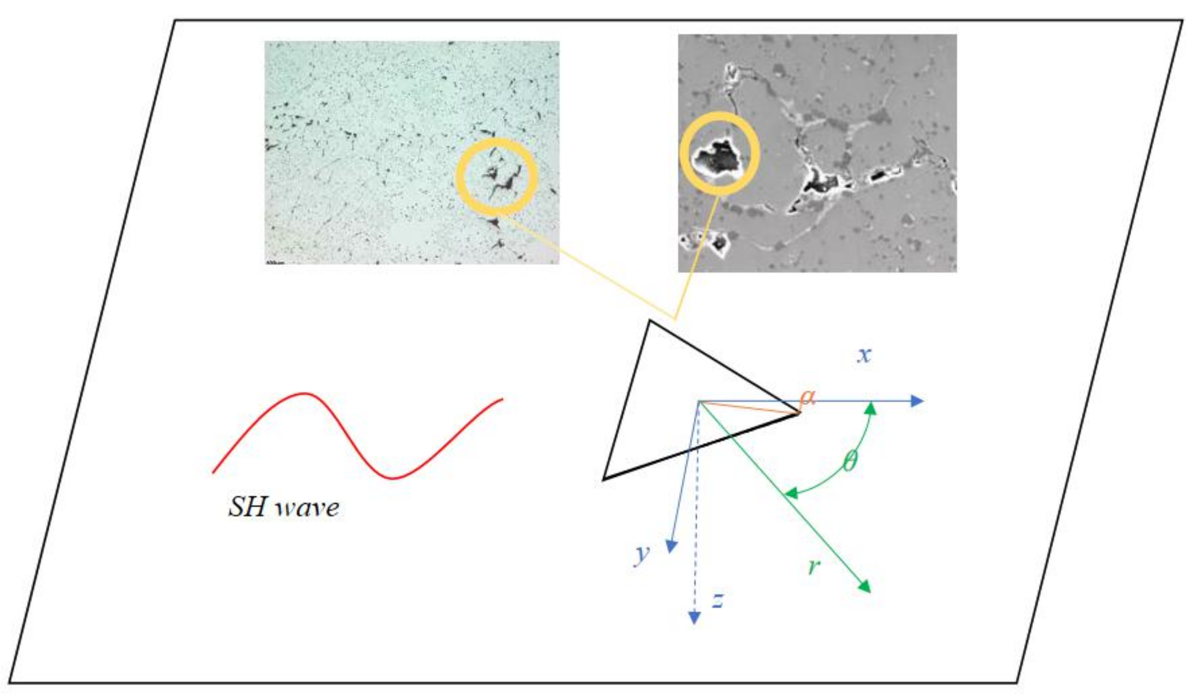
2. The Basic Equations of Two-Dimensional Anti-plane Problems in Cylindrical Coordinates

Piezoelectric materials usually work under dynamic loads, and we use incident elastic waves to simulate a variety of dynamic loads. Among these waves, the dynamic stress concentration caused by the anti-plane shear wave (SH wave) is usually used as the calculation basis for the stress field strength factor of the III-type dynamic fracture. Therefore, the anti-plane shear wave (SH wave) is used as the incident wave in this paper. The SH wave can transform the three-dimensional electroelastic coupling problem into a two-dimensional anti-plane problem.
According to the defect microstructure of BCZT material, many micron-scale irregular defects will be generated on the material during processing and application. In particular, the near-triangular defect has serious stress concentration due to its special shape. A simplified model of an embedded triangular defect in an infinite piezoelectric material is shown in Figure 1. The piezoelectric material is set to be uniform and homogeneous. The SH wave propagates in the positive x direction in the infinite piezoelectric material.
In Figure 1 ( x , y , z ) is a rectangular coordinate system, ( r , θ , z ) is a cylindrical coordinate system, and α is the minimum value of the absolute value of the angle between all the median lines of the triangle and the x-axis.
In a rectangular coordinate system, the coupling characteristics between mechanical deformation and electric field of composite piezoelectric materials can be described by the following constitutive equation
σ i j = c i j k l ε k l e i j k E k D i = e i k l ε k l + κ i k E k
where ε i j , E i are strain and electric field intensity, respectively, σ i j , D i are stress and electric displacement, respectively, c i j k l , e i j k and κ i k are elastic, piezoelectric, and dielectric constants, respectively. Under the assumption of small deformation, strain and electric field can be expressed by displacement u i and electric potential φ as follows
ε i j = u i , j + u j , i / 2 E i = φ , i
The subscript “ , i “ represents the partial derivative with respect to the coordinate x i . In the quasi-static electromagnetic approximation, the stress σ i j and electric displacement D i should satisfy the following equilibrium equation
σ i j , j = ρ 2 u i t 2 D i , i = 0
where t stands for time and ρ represents density. The repeated index in the formula represents the summation. By substituting (2) into (1) and then (3), the differential control equation of displacement and electric potential can be obtained as follows.
c i j k l u k , l j + e i j k φ , k j = ρ 2 u i t 2 e i k l u k , l j ε i k φ , k i = 0
The tensor form is used in the derivation (Equations (1)–(4)) and can be applied to any dynamical problem of piezoelectric material. For the two-dimensional anti-plane problem, the out-of-plane displacement and in-plane electric field are only functions of coordinates x and y , and all physical quantities depend only on the anti-plane displacement u 3 and in-plane electric potential φ .
u 1 = u 2 = 0 u 3 = u 3 x , y φ = φ x , y
According to these simplification conditions, complex tensor form can be reduced to vector form. Substituting Equation (5) into Equation (4), Equation (4) can be converted
( c 3131 2 u 3 x 2 + c 3232 2 u 3 y 2 ) + ( e 311 2 φ x 2 + e 322 2 φ y 2 ) = ρ 2 u 3 t 2 ( e 131 2 u 3 x 2 + e 232 2 u 3 y 2 ) + ( e 11 2 φ x 2 + e 22 2 φ y 2 ) = 0
The components of the rectangular coordinate system ( x , y , z ) and the components of the cylindrical coordinate system ( r , θ , z ) have the following transformation relationship
r 2 = x 2 + y 2 r cos θ = x r sin θ = y
According to Equation (6) and (7), u 3 is denoted by w for simplicity, and the basic equation of two-dimensional anti-plane problem in cylindrical coordinate system can be obtained as follows
c 44 ( 1 r 2 2 w θ 2 + 2 w r 2 + 1 r w r ) + e 15 ( 1 r 2 2 ϕ θ 2 + 2 ϕ r 2 + 1 r ϕ r ) = ρ 2 w t 2 e 15 ( r 2 w r 2 + 1 r 2 w θ 2 + w r ) - ε 11 ( r 2 ϕ r 2 + 1 r 2 ϕ θ 2 + ϕ r ) = 0

3. Solutions of Incident, Scattered, and Total Electroelastic Waves in Piezoelectric Materials with Triangular Defects

The resulting basic equations are electroelastically coupled and need to be decoupled. Assume that a constructor function γ = ϕ e 15 ε 11 w is used to simplify (8) [28]. The result is shown below:
1 r 2 2 w θ 2 + 2 w r 2 + 1 r w r = 1 c s 2 2 w t 2 1 r 2 2 γ θ 2 + 2 γ r 2 + 1 r γ r = 0
where c s = χ / ρ 0 is the propagation velocity of SH waves, χ = c 44 + e 15 2 / ε 11 . After simplifying the equation with Laplace operator, wave equation and Laplace equation are obtained
2 w = 1 c s 2 2 w t 2 2 γ = 0
Since Equation (10) are classical differential equations, the form of their solution can be easily obtained. Therefore, we can obtain the displacement field and electric potential field of the scattered wave as follows
w s = n = A n H n ( 1 ) ( k r ) e i n θ γ = n = 0 B n k n r n e i n θ ϕ s = e 15 ε 11 w s + γ
in which A n is the undetermined coefficient to describe the scattered elastic wave field, B n is the undetermined coefficient to describe the scattered potential field, and H n 1 is the n-th order Bessel function of the third kind. Additionally, k = ω / c s is the incident wave number.
Considering the incident SH wave propagating in the positive × direction, it is possible to find the expansion of its displacement field and potential field in the polar coordinate system as
w i = w 0 n = i n J n ( k r ) e i n θ ϕ i = e 15 ε 11 w i
The incident field and the scattered field are superimposed, and the total field of the elastic wave and total potential field in the piezoelectric material are expressed as
w t = w i + w s ϕ t = e 15 ε 11 ( w i + w s ) + γ

4. Boundary Conditions and Determination of Mode Coefficients

Since the boundary conditions of the triangle are more complicated, adopt complex variable function method, introduce complex variable
ζ = x + i y = r ( cos θ + i sin θ ) ζ ¯ = x i y = r ( cos θ i sin θ )
Then, conformal mapping technology can be used to map the outer domain (inner domain) of the triangle defect boundary L on the plane ζ to the outer domain (inner domain) of the unit circle of the boundary S on the η plane. The function can take the following form:
ζ = Ω ( η ) = a 1 η 1 3 ( 1 η ) 2 + 1 45 ( 1 η ) 5
where a is the shape parameter of the triangle, the side length. The boundary conditions in plane η can be written as
τ ρ z | ρ = a = 0 D ρ | ρ = a = D ρ c | ρ = a = ε 11 ϕ c r | ρ = a ϕ ( t ) | ρ = a = ϕ c
The superscript c refers to the inside of the defect. Substitute the conformal transformation formula into the scattered wave formula
w ( s ) = n = A n H n ( 1 ) ( k Ω ( η ) ) Ω ( η ) Ω ( η ) n ϕ ( s ) = e 15 ε 11 w ( s ) + n = 0 B n k n ( Ω ( η ) ¯ ) n
Substitute the conformal transformation formula into the incident wave formula
w ( i ) = w 0 n = i n J n ( k Ω ( η ) ) Ω ( η ) Ω ( η ) n ϕ ( i ) = e 15 ε 11 w ( i ) = w 0 e 15 ε 11 n = i n J n ( k Ω ( η ) ) Ω ( η ) Ω ( η ) n
The total elastic wave field and potential field can be written as
w ( t ) = n = w 0 i n J n ( k Ω ( η ) ) + A n H n ( 1 ) ( k Ω ( η ) ) Ω ( η ) Ω ( η ) n ϕ ( t ) = e 15 ε 11 n = w 0 i n J n ( k Ω ( η ) ) + A n H n ( 1 ) ( k Ω ( η ) ) Ω ( η ) Ω ( η ) n + n = 0 B n k n ( Ω ( η ) ¯ ) n
Substituting Equations (17)–(19) into Equation (16), the boundary conditions under the conformal transformation can be obtained
τ ρ z | ρ = a = 0 τ ρ z = c 44 ( w ζ e i θ + w ζ ¯ e i θ ) + e 15 ( ϕ ζ e i θ + ϕ ζ ¯ e i θ ) = k 2 c 44 ( 1 + e 15 2 c 44 ε 11 ) n = w 0 i n w 0 i n η ρ Ω ( η ) Ω ( η ) J n 1 ( k Ω ( η ) ) Ω ( η ) Ω ( η ) n 1 η ¯ ρ Ω ( η ) ¯ Ω ( η ) J n + 1 ( k Ω ( η ) ) Ω ( η ) Ω ( η ) n + 1 + A n η ρ Ω ( η ) Ω ( η ) H ( 1 ) n 1 ( k Ω ( η ) ) Ω ( η ) Ω ( η ) n 1 η ¯ ρ Ω ( η ) ¯ Ω ( η ) H ( 1 ) n + 1 ( k Ω ( η ) ) Ω ( η ) Ω ( η ) n + 1 e 15 n = 0 B n n k n η ¯ ρ Ω ( η ) ¯ Ω ( η ) ( Ω ( η ) ¯ ) n 1 D ρ | ρ = a = D ρ c | ρ = a = ε 11 ϕ c r | ρ = a
D ρ = ε 11 n = 0 B n n k n η ¯ ρ Ω ( η ) ¯ Ω ( η ) Ω ( η ) ¯ n 1 = ε 0 n = 0 C n n k n η ρ Ω ( η ) Ω ( η ) Ω ( η ) n 1 ϕ ( t ) | ρ = a = ϕ c e 15 ε 11 n = A n H n ( 1 ) ( k Ω ( η ) ) Ω ( η ) Ω ( η ) n + B n k Ω ( η ) n Ω ( η ) Ω ( η ) n n = 0 C n k Ω ( η ) n Ω ( η ) Ω ( η ) n = e 15 ε 11 n = w 0 i n J n ( k Ω ( η ) ) Ω ( η ) Ω ( η ) n
It is possible to define the boundary conditions as an infinite algebraic equation system considering:
n = E n X n = E
where
E n = E 11 E 11 E 11 E 21 E 22 E 23 E 31 E 32 E 33 X n = A n B n C n E = E 1 E 2 E 3
Multiply both ends of equation by e i s θ (s = 1,2…3n), and use the orthogonality of the function system to obtain
n = E n s X n = E s
where
E n = E 11 n E 11 n E 11 n E 21 n E 22 n E 23 n E 31 n E 32 n E 33 n X n j = A n 1 A n 2 B n E s = E 1 E 2 E 3
E 11 n = k 2 c 44 1 + e 15 2 c 44 ε 11 η ρ Ω η Ω η H n 1 ( 1 ) k Ω η Ω ( η ) Ω ( η ) n 1 η ¯ ρ Ω η ¯ Ω η H n + 1 ( 1 ) k Ω η Ω ( η ) Ω ( η ) n + 1 E 12 n = e 15 n k n η ¯ ρ Ω η ¯ Ω η Ω ( η ) ¯ n 1 E 13 n = 0 E 1 = k c 44 2 1 + e 15 2 c 44 ε 11 w 0 i n η ρ Ω η Ω η J n 1 k Ω η Ω ( η ) Ω ( η ) n 1 η ¯ ρ Ω η ¯ Ω η J n + 1 k Ω η Ω ( η ) Ω ( η ) n + 1 E 21 n = 0 E 22 n = ε 11 n = 0 B n k n η ¯ Ω η ¯ Ω ( η ) ¯ n 1
E 23 n = ε 0 n = 0 C n k n η Ω η Ω ( η ) n 1 E 2 = 0 E 31 n = e 15 ε 11 H n ( 1 ) k Ω ( η ) Ω ( η ) Ω ( η ) n E 32 n = k Ω ( η ) n Ω ( η ) Ω ( η ) n E 33 n = k Ω ( η ) n Ω ( η ) Ω ( η ) n E 3 = e 15 ε 11 w 0 i n J n k Ω ( η ) Ω ( η ) Ω ( η ) n
According to Equation (22), we can derive the infinite system of linear equations for computing the mode coefficients A n , Β n , C n , where n = ~ + .

5. Dynamic Stress Concentration Factor

DSCF is used to describe the stress concentration around the defect. According to the definition of DSCF, DSCF is the ratio of the hoop dynamic stress on the periphery of the defect to the hoop stress amplitude of the incident wave in the incident direction [29].
D S C F = τ θ z τ 0
where τ 0 = w 0 χ k and
τ θ z = c 44 1 r w θ + e 15 1 r φ θ
According to the derivation rule, we can obtain
τ θ z = c 44 i ( w ζ e i θ w ζ ¯ e i θ ) + e 15 i ( φ ζ e i θ φ ζ ¯ e i θ )
and
w t ζ = k 2 n = + [ w 0 i n J n 1 ( k Ω ( η ) ) + A n H n 1 1 ( k Ω ( η ) ) ] [ Ω ( η ) Ω ( η ) ] n 1 w t ζ ¯ = k 2 n = + [ w 0 i n J n + 1 ( k Ω ( η ) ) + A n H n + 1 1 ( k Ω ( η ) ) ] [ Ω ( η ) Ω ( η ) ] n + 1 ϕ t ζ = k e 15 2 ε 11 n = + [ w 0 i n J n 1 ( k Ω ( η ) ) + A n H n 1 1 ( k Ω ( η ) ) ] [ Ω ( η ) Ω ( η ) ] n 1 ϕ t ζ ¯ = k e 15 2 ε 11 n = + [ w 0 i n J n + 1 ( k Ω ( η ) ) + A n H n + 1 1 ( k Ω ( η ) ) ] [ Ω ( η ) Ω ( η ) ] n + 1 n = 0 + n B n k n Ω ( η ) ¯ ( n + 1 )
Thus, the DSCF around the cylindrical defect in piezoelectric material is expressed as
D S C F = k 2 c 44 i ( 1 + e 15 2 c 44 ε 11 ) n = + η a [ w 0 i n J n 1 ( k Ω ( η ) ) + A n H n 1 1 ( k Ω ( η ) ) ] [ Ω ( η ) Ω ( η ) ] n 1 + A n H n + 1 1 ( k Ω ( η ) ) ] [ Ω ( η ) Ω ( η ) ] n + 1 + η ¯ a [ w 0 i n J n + 1 ( k Ω ( η ) ) + e 15 i n = 0 + η ¯ a n B n k n Ω ( η ) ¯ ( n + 1 )

6. Numerical Examples Simulation and Discussion

The above derivation applies to any piezoelectric material with known material parameters. Due to the characteristics of Bessel functions, the coefficients ( A n , Β n , C n ) tend to approach 0 as n increases. We can select a suitable minimum value of n according to the required precision and truncate the DSCF. Finally, we can obtain an approximate solution of DSCF with the required accuracy.
As a lead-free piezoelectric material with excellent piezoelectric properties, BCZT has broad application prospects, and it is necessary to analyze the stress concentration of the material in the application. Therefore, in this paper, (Ba0.85Ca0.15)(Zr0.1Ti0.9)O3 of BCZT is used as a specific calculation example, and its initial related material constants are obtained by conventional tests on the samples as follows
ρ 0 = 5.3 × 10 3 k g m 2 · c 440 = 15 × 10 10 N m 2 e 150 = 10.9 N / V m , ε 110 = 220.8 × 10 10
Raziye et al. [30] found through experiments that Ce doping can improve the piezoelectric properties of materials, and the amount of Ce doping and sintering temperature will affect the piezoelectric constant of materials. In addition, the data in this special temperature range can also be used to analyze the state of spacecraft-related equipment under high temperature conditions. According to the experimental results and related formulas, the piezoelectric constant of the material changes with the amount of Ce doping and temperature as shown in Figure 2 below:
For this case study, it is possible to evaluate the stress for a steady-state elastic wave incident along the x-axis and parallel to the deflection angle of the triangular defect (alpha = 0); see Figure 1. According to the dynamic stress concentration formula derived above, the dynamic stress concentration will change with the wave number of the incident elastic wave and the piezoelectric constant of the material. By adjusting the dimensionless wave number ka of the incident wave, the dynamic stress concentration factor at different temperatures and Ce doping amounts are shown in the following Figure 3, Figure 4, Figure 5, Figure 6 and Figure 7.
We chose the range of ka as 0–5 commonly used in solid mechanics. If it exceeds this range, the change will tend to be stable [29].
The above conclusions are all when α = 0 . Due to the particularity of the triangle, different α also affect the stress concentration of the defects. Here we take BCCe0.05ZT as an example to explore the effect of α on stress concentration.

7. Conclusions

In this paper, the stress concentration problem of e-type piezoelectric material under electroelastic coupling wave is studied. Firstly, the problem is simplified as a two-dimensional inverse plane problem. The force-electric coupling field is decomposed into the form of a Laplace equation and wave equation by using the constructor, and then the analytical solution of the stress concentration factor around the defect is obtained by using the separation variable method and the affine transformation method. By a program, the dynamic stress concentration factor of a triangular defect on a special piezoceramics ((Ba0.85Ca0.15)(Zr0.1Ti0.9)O3) under the influence of electroelastic waves is calculated, and the following conclusions are finally drawn.
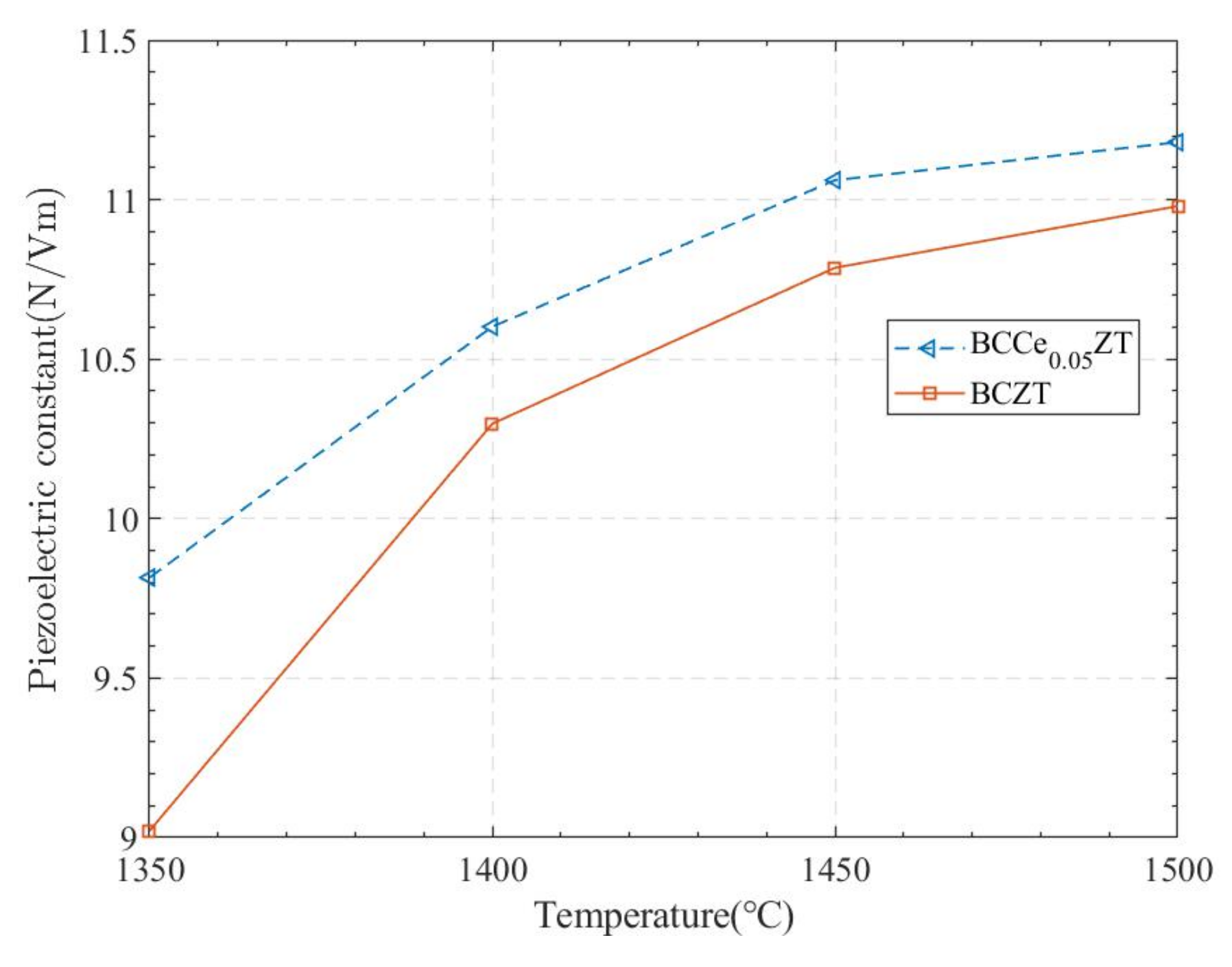
  • Supported by the currently available data, Ce doping and elevated temperature (between 1350–1500 °C) will increase the piezoelectric constant of the (Ba0.85Ca0.15)(Zr0.1Ti0.9)O3.
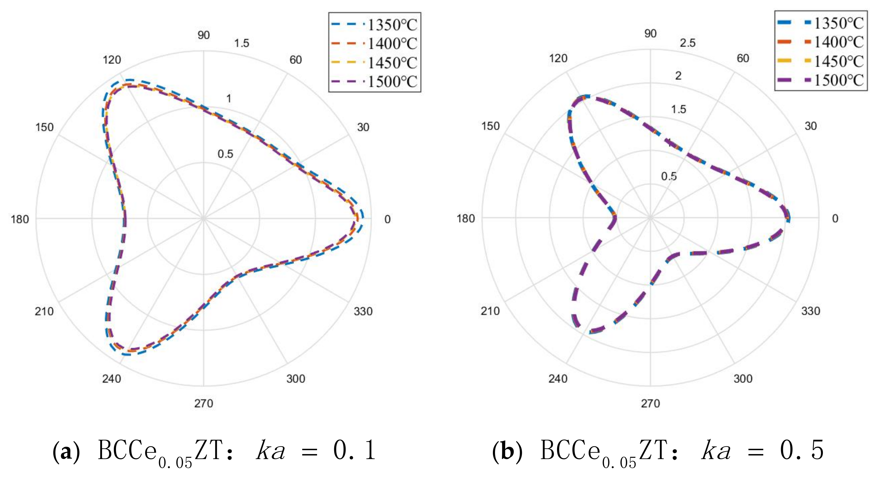
  • As ka increases, the stress concentration around the defect fluctuates more violently, and the increase of the piezoelectric coefficient e 15 will make the stress concentration more serious. In addition, the stress concentration of the triangular defects is obvious at the three vertices.
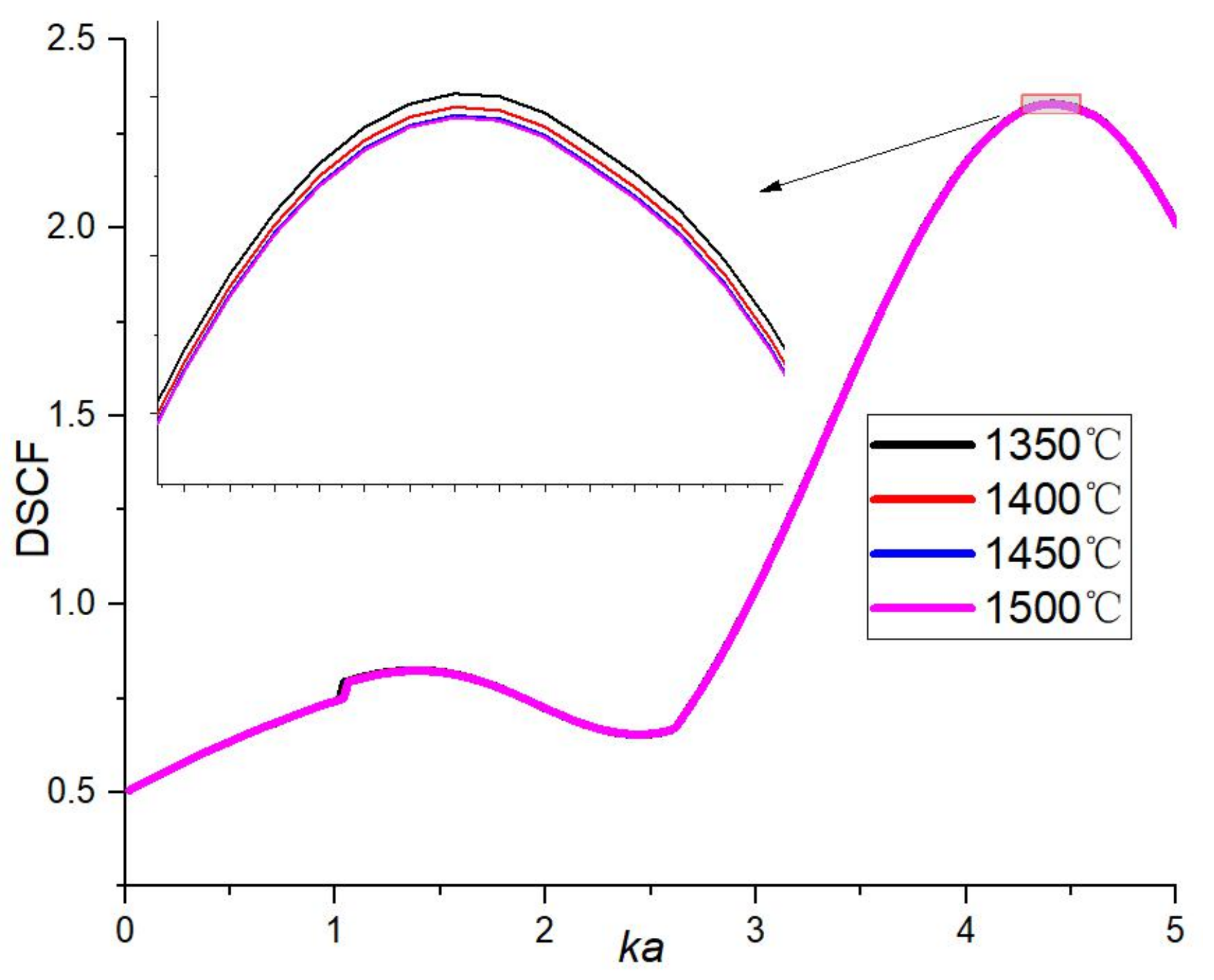
  • When ka changes from 0 to 5, the stress concentration trend around the defect is similar to that of ka = 0.1 and ka = 0.5. The only thing that changes greatly is the maximum value of stress concentration (stress concentration coefficients on the three vertices). With the increase of ka, the maximum value of the stress concentration factor has a general trend of first increasing and then decreasing. The stress concentration factor peaks in the range of ka = 4~5.
  • Under different deflection angles, the stress concentration phenomenon is still concentrated at the vertex of the triangle. However, as the deflection angle α increases, the magnitude of the stress concentration factor becomes smaller.
  • The maximum value of the stress concentration factor decreases as the absolute value of the deflection angle increases. The variation trend of the maximum stress concentration factor with α can be considered to be almost symmetric at about x = 0 and take a maximum value at x = 0.
  • The difference in temperature and the amount of Ce doping is essentially the difference in piezoelectric constant. Within the data range of this study, the better the piezoelectric performance, the more intense the piezoelectric effect and the greater the magnitude of the stress concentration factor.
The theoretical and numerical results in this paper are expected to be applied in the dynamic analysis and strength design of piezoelectric material structures and provide suggestions for the subsequent large-scale application and production of BCZT materials. By changing the piezoelectric material constant and conformal transformation formula in this analysis, the DSCF of any shape defect on any piezoelectric material can theoretically be obtained.

Author Contributions

Conceptualization, C.Z. and H.J.; methodology, J.L.; validation, J.L., J.F., and X.H.; formal analysis, Y.G.; investigation, W.Z. and J.L.; data curation, J.L. and J.B.; writing—original draft preparation, J.L.; writing—review and editing, C.Z.; supervision, H.J.; project administration, Y.G.; funding acquisition, W.Z. and J.N. All authors have read and agreed to the published version of the manuscript.

Funding

This research was supported by the Sichuan Science and Technology Program (No. 2022YFG0274), the Key Research and Development Program of Zhejiang Province (No. 2021C03013), the National Natural Science Foundation of China (Grant No. 51875146), the Natural Science Foundation of Zhejiang Province (Grant No. LY21E050005), and the Key Laboratory for Technology in Rural Water Management of Zhejiang Province (ZJWEU-RWM-20200303B).

Institutional Review Board Statement

Not applicable.

Informed Consent Statement

Not applicable.

Data Availability Statement

Not applicable.

Conflicts of Interest

The authors declare no conflict of interest.

References

  1. Jaffe, B.; Cook, W.R.; Jaffe, H. Piezoelectric Ceramic; Academic Press: Cambridge, MA, USA, 1971. [Google Scholar]
  2. Juergen, R.; Li, J.F. Lead-free piezoceramics: Status and perspectives. MRS Bull. 2018, 43, 576–580. [Google Scholar] [CrossRef] [Green Version]
  3. Takenaka, T.; Okuda, T.; Takegahara, K. Lead-free piezoelectric ceramics based on (Bi1/2Na1/2)TiO3-NaNbO3. Ferroelectrics 1997, 196, 175–178. [Google Scholar] [CrossRef]
  4. Takenaka, T. Piezoelectric properties of some lead-free ferroelectric ceramics. Ferroelectrics 1999, 230, 87–98. [Google Scholar] [CrossRef]
  5. Nagata, H.; Takenaka, T. Additive effects on electrical properties of (Bi1/2 Na1/2)TiO3 ferroelectric ceramics. J. Eur. Ceram. Soc. 2001, 21, 1299–1302. [Google Scholar] [CrossRef]
  6. Saito, Y.; Takao, H.; Tani, T. Lead-free piezoceramics. Nature 2004, 432, 84–87. [Google Scholar] [CrossRef] [PubMed]
  7. Takenaka, T.; Nagata, H. Current status and prospects of lead-free piezoelectric ceramics. J. Eur. Ceram. Soc. 2005, 25, 2693–2700. [Google Scholar] [CrossRef]
  8. Berlincourt, D.A. Piezoelectric and piezomagnetic materials and their function in transducers. Phys. Acoust. 1964, 1, 169–270. [Google Scholar] [CrossRef]
  9. Wu, Y.H.; Ma, F.; Qu, J.K. Enhanced mechanical and piezoelectric properties of BCZT-CuY/rGO-based nanogenerator for tiny energy harvesting. Mater. Lett. 2018, 231, 20–23. [Google Scholar] [CrossRef]
  10. Sun, M.; Li, P.; Hu, C.; Du, J.; Li, W. Polarization-induced phase structure transition and change of photoluminescence in Er 3+ -doped (Ba, Ca)(Ti, Sn)O 3 -based multifunctional ceramics. J. Mater. Sci. 2021, 56, 10204–10217. [Google Scholar] [CrossRef]
  11. Wu, K.; Wang, H.; Zhou, X. Large energy storage density and efficiency of Sm2O3 -doped Ba 0.85 Ca 0.15 Zr 0.08 Ti 0.92 O 3 lead-free ceramics. J. Mater. Sci. 2021, 32, 1–11. [Google Scholar] [CrossRef]
  12. Chandraiah, M.; Panda, P.K. Effect of dopants (A=Mg2+, Ca2+ and Sr2+) on ferroelectric, dielectric and piezoelectric properties of (Ba1xAx) (Ti0.98Zr0.02) O3 lead-free piezo ceramics. Ceram. Int. 2015, 41, 8040–8045. [Google Scholar] [CrossRef]
  13. Koruza, J.; Bell, A.J.; Frmling, T. Requirements for the Transfer of Lead-free Piezoceramics into Application. J. Mater. 2018, 4, 13–26. [Google Scholar] [CrossRef]
  14. Parton, V.Z. Fracture mechanics of piezoelectric materials. Acta Astronaut. 1976, 3, 671–683. [Google Scholar] [CrossRef]
  15. Sosa, H. Plane problems in piezoelectric media with defects. Int. J. Solids Struct. 1991, 28, 491–505. [Google Scholar] [CrossRef]
  16. Liu, W.; Ren, X. Large Piezoelectric Effect in Pb-Free Ceramics. Phys. Rev. Lett. 2009, 103, 257602. [Google Scholar] [CrossRef] [Green Version]
  17. Barnett, D.M.; Asaro, R.J. The fracture mechanics of slit-like cracks in anisotropic elastic media. J. Mech. Phys. Solids 1972, 20, 353–366. [Google Scholar] [CrossRef]
  18. Xu, X.L.; Rajapakse, R. On a plane crack in piezoelectric solids. Int. J. Solids Struct. 2001, 38, 7643–7658. [Google Scholar] [CrossRef]
  19. Mcmeeking, R.M. The energy release rate for a Griffith crack in a piezoelectric material. Eng. Fract. Mech. 2004, 71, 1149–1163. [Google Scholar] [CrossRef]
  20. Pak, Y.E. Linear electro-elastic fracture mechanics of piezoelectric materials. J. Appl. Mech. 1992, 112, 79–100. [Google Scholar] [CrossRef]
  21. Wang, X.; Yong, Z.; Zhou, W. A novel hybrid finite element with a hole for analysis of plane piezoelectric medium with defects. Int. J. Solids Struct. 2004, 41, 7111–7128. [Google Scholar] [CrossRef]
  22. Liang, Y.C.; Sun, Y.P.; Wu, L.N. Hole problems in a circular piezoelectric plate. T Can. Soc. Mech. Eng. 2016, 40, 491–500. [Google Scholar] [CrossRef]
  23. Kaloerov, S.A.; Glushchenko, Y.A. Electroelastic State of a Multiply Connected Piezoelectric Half Plane with Holes and Cracks. J. Math. Sci. 2001, 107, 4416–4424. [Google Scholar] [CrossRef]
  24. Xiao, J.H.; Xu, Y.L.; Zhang, F.C. Fracture characteristics of a cracked equilateral triangle hole with surface effect in piezoelectric materials. Theor. Appl. Fract. Mec. 2018, 96, 476–482. [Google Scholar] [CrossRef]
  25. Xiao, J.; Xu, Y.; Zhang, F. Fracture Characteristics of Cracked Hole in Piezoelectric Solids Considering Surface Effect. Acta Mech. Solida Sinica 2019, 40, 269–276. [Google Scholar] [CrossRef]
  26. Xiao, J.; Xu, B.X.; Xu, Y. Fracture analysis on a cracked elliptical hole with surface effect in magnetoelectroelastic solid. Theor. Appl. Fract. Mec. 2020, 107, 102532. [Google Scholar] [CrossRef]
  27. Dai, M.; Schiavone, P. An anisotropic piezoelectric half-plane containing an elliptical hole or crack subjected to uniform in-plane electromechanical loading. J. Mech. Mater. Struct. 2016, 11, 433–448. [Google Scholar] [CrossRef]
  28. Zhou, C.; Chao, H.; Ma, F. Elastic wave scattering and dynamic stress concentrations in exponential graded materials with two elliptic holes. Wave Motion. 2014, 51, 466–475. [Google Scholar] [CrossRef]
  29. Pao, Y.H.; Mow, C.C.; Achenbach, J.D. The diffraction of elastic wave and dynamic stress concentration. J. Appl. Mech.-T Asme. 1973, 40, 213–219. [Google Scholar] [CrossRef] [Green Version]
  30. Hayati, R.; Bahrevar, M.A.; Ganjkhanlou, Y. Electromechanical properties of Ce-doped(Ba0.85Ca0.15)(Zr0.1Ti0.9)O3 lead-free piezoceramics. J. Adv. Ceram. 2019, 10, 186–195. [Google Scholar] [CrossRef] [Green Version]
Figure 1. Schematic diagram of the setting of the coordinate system and the incidence of SH waves (The inserted figures (unpublished) show triangular-like microcracks observed by scanning electron microscopy for BCZT and other ferroelectric ceramics.).
Actuators 11 00106 g001
Figure 2. Variation of Piezoelectric Constant with Ce Doping and Temperature.
Actuators 11 00106 g002
Figure 3. Polar plot of stress concentration of BCZT at different incident wavenumbers and temperatures.
Actuators 11 00106 g003
Figure 4. Polar plot of stress concentration of BCCe0.05ZT at different incident wavenumbers and temperatures.
Actuators 11 00106 g004
Figure 5. Variation of maximum stress concentration factor of BCCe0.05ZT with ka.
Actuators 11 00106 g005
Figure 6. Stress concentration graph under different α ( BCCe 0.05 ZT : k a = 0.5 ) .
Actuators 11 00106 g006
Figure 7. Graph of maximum stress concentration factor versus α .
Actuators 11 00106 g007
Publisher’s Note: MDPI stays neutral with regard to jurisdictional claims in published maps and institutional affiliations.

