1. Introduction
High precision micro conveyances devices, as important elements in high precision positioning systems [
1,
2,
3], play vital roles in many scientific and industrial fields, such as bio-medicine [
4,
5], optical systems [
6], micro-factory [
7,
8], micro-manipulation [
9,
10,
11], etc. The stick-slip principle, which can achieve large precise displacement with high efficiency and generate large actuating force [
12], is an ideal principle for high precision driving, having drawn widespread attention. The main drawback is its backward motion [
13,
14,
15,
16,
17]. In recent years, many micro conveyance devices [
1,
2,
3,
6,
18,
19] based on the stick-slip principle have been rapidly developed.
In the literature, the stick-slip-based micro conveyance devices were mostly realized by using analogical actuators. These devices [
2,
20,
21,
22] were often adopted with closed loop controls to reach high performance levels. Sensors and closed loop controls are indispensable to such devices. However, with the miniaturization of precision systems, it is required that the micro conveyance device should have a compact size and be easy to integrate, especially for applications where it is difficult to integrate sensors. Moreover, the integration of sensors for the above-mentioned design may lead to expansive mechanical setup and complex control.
Digital actuators suggest an alternative to the design of micro conveyance devices so as to avoid the abovementioned problems. Digital actuators can be switched between well-known and repeatable discrete/stable positions [
23]. During the switching of a digital actuator, a fixed output stroke can be realized. Energy consumption is only needed during the switching process between the discrete/stable positions. The repeatability of the fixed stroke enables the open loop control for these actuators [
24,
25,
26,
27]. Sensors are not needed, and the integration of such devices are also simplified. Pulsing signals can be used for the open loop control which reduce the control complexity. The other advantages of the digital actuators include their simple structure, low cost, small Joule heat effect, etc. [
28,
29]. The main drawback is that the manufacturing errors of these actuators have to be precisely controlled, as they cannot be compensated using the control law.
Aiming to profit from the advantages of the digital actuation principle, this work presents the modeling and experimental validation of a micro conveyance device consisting of eight digital actuators (fabricated in UTC). With a specific control strategy, a conveyance application can be realized, and the backward motion can be eliminated theoretically. The control strategy is verified in the designed device in this work, and it can also be applied to the other similar designs to eliminate backward motion.
The rest of paper is divided into five sections. The operating principle of the stick-slip conveyance device is introduced in
Section 2. In
Section 3, the device dynamic modeling principle is introduced. In
Section 4, an experiment system is established, and the measurement of the prototype device is carried out. In
Section 5, a series of experiments are conducted to validate the proposed design and show the performance of the prototype device. The results are also listed and discussed. Finally,
Section 6 concludes the paper and prospective future research is outlined.
2. Principle
2.1. Principle of the Elementary Digital Actuator
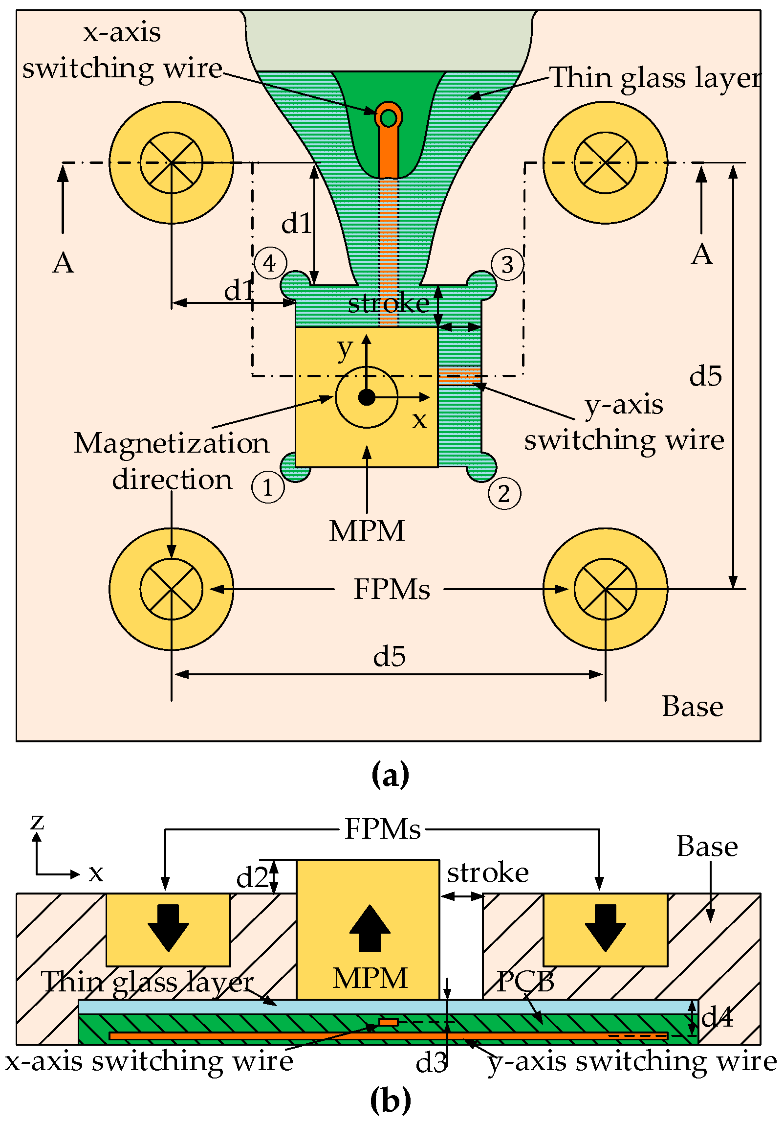
The elementary digital actuator consists of a mobile part and a fixed part in
Figure 1. The mobile part is a Movable Permanent Magnet (MPM) placed in the square cavity made of aluminum. The fixed part consists of four Fixed Permanent Magnets (FPMs) assembled around the square cavity and two orthogonal wires (
x- and
y-axis switching wires) placed below the square cavity. The MPM can reach the four corners of the square cavity which correspond to the four stable positions (①②③④) of the actuator. The four FPMs generate a magnetic force on the MPM along the two orthogonal axes (
x- and
y-axis). This force ensures the holding of the MPM in each corner of the square cavity without external energy supply.
To switch the MPM between the stable positions, the orthogonal electric wires placed below the square cavity are used. When a current passes through a wire surrounded by the magnetic flux density from the MPM, a Lorentz force is generated between the MPM and the wire. The MPM is then switched from one stable position to another.
In the previous study [
23,
30], research on the actuators optimization design were carried out; a double side Printed Circuit Board (PCB) was used to avoid any electrical contact between the two orthogonal wires (
Figure 1). A thin glass layer was placed between the MPM and the PCB so as to avoid electrical contact between the MPM and the wires. This thin glass layer also ensures a flat surface on which the MPM moves. The dimensions and the properties of the actuator are given in
Table 1.
2.2. Principle of the Micro Conveyance Device
The micro conveyance device consists of eight elementary actuators which are arranged symmetrically in plane (
Figure 2). The conveyed object is a plate placed on the device which is just in contact with the MPMs of the eight elementary actuators. In order to realize the conveyance application of the device, the stick-slip driving principle was adopted.
According to the stick-slip driving principle, a specific control strategy was used to realize the displacement of the conveyed plate. This control strategy can be explained by the realization of a complete conveyed plate driving sequence. The complete driving sequence of the conveyed plate can be divided into two processes: the “slip” process and the “stick” process. In the “slip” process, all the MPMs are actuated from one stable position to another simultaneously via the control signal (pulse current). The plate is then actuated by the friction forces (between each MPM and the plate) conveying displacement, which is called step size displacement (SSD), illustrated in
Figure 2. This “slip” process is regarded as the major step in the following expression. In the “stick” process, the MPMs are actuated back to their initial stable position one after another by reversing the control signal, respectively. Theoretically, no backward motion of the plate is generated due to the insufficient friction forces. This “stick” process includes eight separate actuations of the MPMs which are regarded as eight small steps, respectively.
As each elementary actuator can be actuated in both the
x- and
y-axis direction, the planar conveyance application of the device can then be realized by repeating the complete driving sequence (“slip” to “stick” process) [
25]. An optimization design of the conveyance device was also carried out to ensure the homogeneous behavior of all elementary actuators in the previous research [
23,
31]. The dimensions and the properties of the conveyance device are given in
Table 1.
3. Dynamic Modeling
Comprehensive dynamic modeling of the device was established to analyze the dynamic characteristics and predict the displacement output of the conveyed plate.
During the movement of the device, the forces exerted on each actuator and the plate constantly changed with the position change of the plate and each MPM in the device. Four different types of forces were considered in the dynamic model: the electromagnetic force (
) between the current-carrying wires and each MPM, the magnetic force (
) between FPMs and MPM, the friction forces (
,
,
) between the moving components and the fixed components and the supporting force (
) between the MPMs and the conveyed plate. (
Figure 3)
According to Newton’s second law, the acceleration of each MPM (
) can be calculated by Equation (1), which is an important parameter for determining the displacement of the plate. If
is not zero, it indicates a non-zero value of the friction force (
), the plate then begins to move. The acceleration (
) of the conveyed plate can be calculated by Equation (2). The theory displacement of the conveyed plate can be achieved through quadratic integral to the acceleration (
).
where,: MPM mass (0.06) (g)
: Conveyed plate mass (0.93) (g)
: Electromagnetic force exerted on each MPM (N)
: Magnetic force (N)
: Top friction force between each MPM and the plate (N)
: Bottom friction force between each MPM and the thin glass layer (N)
: Lateral friction force between each MPM and the base (N)
In order to analyze the dynamic characteristics and predict the displacement output of the conveyed plate, the above-mentioned forces should be calculated first. Four sub-models (electromagnetic force model, magnetic force model, friction force model, mass center shift model) have been created for the calculation, respectively.
3.1. Electromagnetic Force Modeling
The electromagnetic force (
) generated by the considered current-carrying wires and exerted on each MPM can be calculated by Equation (3) [
32].
where,The magnetic flux density generated by each MPM at any point (
x;
y;
z) in the Cartesian coordinate located outside the MPM can be calculated via the magnetic charge model presented in Equations (4)–(6) [
32].
where,: Magnetic flux density components along x-, y- and z-axis, respectively (T)
: Magnetic permeability of air (4π × 10−7) (N·A−2)
: Magnetization of the permanent magnet (A m−1)
: Coordinates of the computing point (m)
: The MPM dimensions (in Figure 4).
3.2. Magnetic Force Modeling
The magnetic force (
) generated by the FPMs and exerted on the considered MPM can be calculated by Equation (7) [
32]. This equation was used to discretize the pole surface area of MPM into sub-surfaces (SF shown in
Figure 4). With the discretization of the MPM pole surface, the magnetic flux density can be computed for each MPM sub-surface with Equations (4)–(6).
where,: Surface charge density (A m−1)
: The magnetic flux density generated by the FPMs at MPM (T)
: SF surface area (m2)
: The center of.
3.3. Friction Force Modeling
Friction force modeling is always a complex problem for the stick-slip-based conveyance devices due to the transition from “stick” to “slip”. For the proposed device, the stick-slip friction forces used to actuate the conveyed plate were considered for the 8 MPM, respectively. In order to simplify the modeling of the friction forces, the classic Coulomb friction model (Equation (8)) was used for the calculation of friction force mentioned in Equations (1) and (2), and the determination of transition from “stick” to “slip” between each MPM and the conveyed plate.
where, 3.4. Mass Center Shift Modeling
During the displacement of the conveyed plate, mass center shift of the plate must be considered, as this phenomenon will result in variation in the friction forces between each MPM and the plate. The variation in friction forces is generated by the variation in supporting forces between each MPM and the plate due to its mass center shift. A sub-model focusing on calculating the supporting forces variation have been created. This sub-model has been integrated to the device dynamic model for the need of precise friction forces modeling of the device.
The calculation of the supporting forces can be expressed with
Figure 5 and Equations (9)–(11). In
Figure 5,
are the supporting forces exerted on the plate by the 8 MPMs, respectively,
O is the calculation coordinate center,
O’ is the centroid of the plate.
where,: Mass of the conveyed glass plate (0.93) (g)
: y-axis offset of mass center (mm)
: x-axis offset of mass center (mm)
: Distance between two adjacent MPMs (mm)
Since the conveyed plate is hyperstatic in the model, supplementary equations are needed for the calculation of the supporting forces from each MPM. During this calculation, two assumptions have been made in order to complete the calculation. The first one is that the MPM is homogeneous and deformable (compressible) at plate gravity. The second one is that the conveyed plate is homogeneous and rigid(non-deformable) in the model. The MPMs deformation (
) relationship can be obtained via the vector co-planar theorem [
33,
34,
35]. The MPMs supporting forces relationship can be obtained via Equation (12) with the help of Hooke’s law (Equation (13)).
where,By using Equations (9)–(13), the variation in the supporting force from each MPM can then be calculated. The variation in friction forces can finally be calculated with Equation (8) according to the actual supporting forces.
The abovementioned four sub-models have been integrated in a device dynamic model. This model was realized in MATLAB/Simulink and the block diagram of the proposed model is shown in
Figure 6. During the simulation, the position information of each MPM and the conveyed plate were fed back to the magnetic force model and the mass center shift mode, respectively. The simulation results are presented in the following Section.
4. Experiment Setup
4.1. Experimental Prototype and Measurements
As is presented in
Figure 2, the prototype device consists of a thin plate, a mechanical base support, FPMs, MPMs, a thin glass layer and a PCB. The experimental prototype has been fabricated by conventional machining in Roberval laboratory (UTC). Non-ferromagnetic material (aluminum) was selected for the base support structure in order to avoid affecting the global magnetic flux density generated by the permanent magnet, and a milling cutter (diameter: 0.8 mm) was used for the milling processing. The aluminum prototype is shown in
Figure 7a.
A geometrical study [
23] of the prototype was carried out to evaluate the influence of the manufacturing errors on the prototype behavior. The eight square cavities dimension of the base support were measured with a white light interferometer machine ZYGOTM at the Roberval laboratory. The error values (
x- and
y-axis) of the eight square cavities in the base support are shown in
Figure 7b,c.
It has been observed that the manufacturing errors (9–29.33 μm and 20.67–50 μm along x- and y-axis, respectively) of the square cavities are irregular and spread over the device. The dimensions of the used MPMs were also measured along the three axes (x-, y- and z-axis); the manufacturing error of the MPMs along the three axes varied from −16 μm to −8 μm.
In order to minimize the square cavities and the MPMs manufacturing error influences on the magnetic forces exerted on each MPM presented in Equation (7), and obtain a homogeneous behavior of the device, eight MPMs were selected and paired with the cavities to obtain an identical stroke of 207 μm in both switching x- and y-axis directions for the eight elementary actuators. The influence of manufacturing errors on the magnetic force change was +0.02 mN and the relative change was +3.2% compared to a perfect stroke of 200 μm.
4.2. Control Equipment Setup
The control system of the device consists of a computer, a PCI data acquisition board (PCI-6733) and four V-A converters (10V-10A). The control flow of the whole control system is shown in
Figure 8a.
LABVIEW software is used for programming and sending control signals to the PCI data acquisition card. The PCI data acquisition card outputs four independent voltage signals, each voltage signal is converted into current signal through the V-A converter and sent to the device.
A non-contact measurement technique based on high frequency capturing camera (FL2-08S2M/C) and a MATLAB image processing program have been developed and implemented, respectively to achieve the plate displacement value. A square marker is pasted at the center of the glass plate surface (
Figure 8b) as a position marker for the measurement. The camera is controlled to take pictures of the plate and transfer pictures to the computer during the displacement of the plate. The stored pictures are processed and calculated by MATLAB program to obtain the displacement of the conveyed plate. The resolution of the camera is 10.42 μm/pixel.
5. Experiments and Analysis
In this section, experimental tests of the prototype have been carried out to validate the design principle and also characterize the dynamic performance of the prototype device and its conveyance application. The influence of driving parameter (driving current), influence of MPM “stick” process, repeatability and the long-range conveyance have been studied via the device dynamic model mentioned above, the simulation results have been compared with the experimental results and discussed.
5.1. Influence of Driving Current
Driving current value is an important parameter as it affects the Lorentz force exerted on each MPM (Equation (3)) furthermore the duration of “stick” and “slip” process of the plate. In this experiment, 20 step size displacement (SSD) in +x direction and then 20 SSD in −x direction have been realized. Current pulse has been used as the driving current to save energy. The duration of the current pulse was set to 20 ms and the current value was set between 5A and 7A. The experimental and simulation average SSD values for different driving current values along
x-axis are presented in
Figure 9a.
It can be observed from
Figure 9a that the changing trend of the experimental results and simulation results are almost consistent, and the maximum difference between the two results value is 13.7% (4.92 μm). With the increase in the driving current value, the difference of results value gradually decreases to the minimum value of 0.7% (0.15 μm), which indicates that the dynamic model can predict the SSD of the conveyed plate within a quite small difference especially when the driving current value is set bigger than 6A.
It can also be observed that with the increase in the driving current value, the experimental and simulation SSD values of the plate decrease from 40.88 μm to 21.61 μm and 35.96 μm to 21.46 μm, respectively. This phenomenon can be explained via a dynamic simulation analysis of MPM. Thanks to the device dynamic model mentioned above, time-displacement curves of MPM and plate during one SSD have been simulated and presented in
Figure 9b. Two driving current values (5A and 7A) are used to make it clear to analyze. Points a and b are the time for each MPM to switch from one stable position to another with 5A and 7A driving current, respectively. They are also the points from which the conveyed plate begins to decelerate during the switching of the MPMs. With a higher current value, the relative slip time between MPMs and the plate becomes less (a < b) due to the augmentation of electromagnetic driving forces exerted on each MPM (Equation (3)). The SSD value of plate then decreases.
5.2. Influence of the “Stick” Process
A complete sequence contains 1 major step and 8 small steps (presented in
Section 2). Theoretically, the plate is stationary without backward motion during the “stick” process (8 small steps). Compared to the other designs in the literature, this important phenomenon is benefitted from the original design of the proposed device and the control strategy mention above. In order to verify the existence of this phenomenon and the theoretical design principle, the influence of each MPM on the plate SSD when it is switched back to its initial stable position one after another (small steps) was studied.
In this experiment and simulation, 5A pulse current is used as driving current with a duration of 20 ms. This current value has been chosen because it ensures the maximum SSD value (
Figure 9a). The “stick” process influence is then maximized and much easier to be observed. Four complete conveyed plate displacement sequences of “slip” process to “stick” process have been implemented along
x-axis direction and the results are illustration in
Figure 10.
It can be observed that the influence of the MPMs “stick” process on the SSD is very small from the experiment results. In
Figure 10, six sticker positions are plotted and zoomed in area A and B. A small variation (less than one pixel) in the plate position was observed when the MPMs were switched back to their initial stable positions (area A and B), which is also the maximum variation in plate position in the complete driving sequence. Consequently, it can be proved that the backward motion is greatly suppressed based on the proposed design and the control strategy is effective.
5.3. “Slip” Process Repeatability Test
In this section, a study on the repeatability of the “Slip” process is presented. The objective of this study is to verify the repeatability of the plate SSD value which is important for the conveyance application. A 5A pulse current was used during this experiment because it can output the maximum SSD and is consistent with previous experiments. During this experiment, the plate was first driven to output an SSD along the +x axis and then the plate was driven to output a SSD along the −x axis. This driving process (defined as forth and back process) was repeated for 30 times; the eight small steps in the “stick” process were not implemented. The plate position along the
x-axis is shown in
Figure 11. The difference (ΔX) (shown in
Figure 11) between the plate current position and the previous position was taken as a repeatability criterion to evaluate the repeatability of the “slip” process SSD. It can be observed that the average SSD value is 41.80 μm and 41.92 μm along the x+/− directions, respectively. The real standard deviations of the SSD value along the two directions are 3.75 μm and 3.70 μm, respectively.
A normal distribution study of the ΔX was carried out with 300 samples of the forth and back process and are illustrated in
Figure 12. It can be observed that most of the ΔX (81.33% (244/300)) is within the measurement resolution (one pixel: 10.42 μm). It is thus proved that the prototype device shows good repeatability in the “slip” process.
5.4. Realization of Long Displacement Conveyance
In this experiment, long displacement plate conveyance was carried out in order to determine the conveyance displacement limit. This experiment was realized using a 5A pulse current with a pulse width of 20 ms. The relation between plate displacement and sequence number is presented in
Figure 13.
In this experiment, 400 complete displacement sequences along the
x-axis direction (“slip” to “stick” process) were realized. It can be observed in
Figure 13 that the trajectory of the plate in the
x-axis direction is almost linear with the increase in sequence number from 0th to 164th (Point a to p). The difference between the average SSD value 37.44 μm and the origin SSD value (40.88 mium) is only 3.44 μm (8.4%); this zone (from a to p) can be determined as the stable zone (SZ). The experimental results and simulation results are almost consistent in the SZ. It can also be observed in the sticker position pictures presented in
Figure 14 that after 150 plate displacement sequences in the
x-axis direction, the
y-axis direction of the plate offset is −175 μm, which is just about four-times the SSD value in the
x-axis direction. It is then proved that the plate displacement linearity is quite good when driven in the
x-axis direction in SZ. The simulated displacement trajectory curve was also found close to the experimental displacement trajectory curve. The dynamic model offers great accuracy under the above driving conditions.
From the 164th to the 218th sequence (Point p to q in
Figure 13), the average SSD value of the plate decreased significantly to 11.92 μm. It was observed in the experiments that the conveyed plate was at the boundary of the actuators. Slight displacements in
y-axis direction (e.g.,
Figure 14e, 347 μm) of the conveyed plate were found which caused the change in the friction forces between each MPM and the plate. This phenomenon, in turn, proves the decrease in the average SSD value of the plate. This zone from Point p to Point q can be defined as the transition zone (TZ). The simulated displacement trajectory curve is not consistent with the experimental displacement trajectory curve in TZ, as boundary effect has not been taken into account in the dynamic model.
After the 220th sequence (Point q), the experimental displacements of the plate are about 0. As it has been observed in experiments, the conveyed plate was already removed from the boundary of the actuators. Several MPMs already lost contact with the plate, which is the reason why the plate ceased to move. This zone after Point q can be defined as the end zone (EZ). The maximum range of the device can be limited to 6880 μm.
5.5. Performance Evaluation and Discussion
The requirements for the stick-slip-based micro conveyance device could vary depending on the application where it is implemented. However, the common requirements are a large active area, planar displacement capabilities (DOF), high speed, high position precision, low energy consumption and suppressed/eliminated backward motion. It has been discussed in the Introduction that the integration of these conveyance devices should be easy, keeping the complexity of these systems as low as possible; thus, the control structure is important for these devices, especially for a compact design need. Comparison has been carried out with several proposed stick-slip-based micro conveyance devices listed in the literature and the performances are shown in
Table 2. The strengths of the proposed design in this work are the mentioned digital actuation principle, simple control, 2-DOF capability, significant active surface, competitive speed, low energy consumption and the elimination of backward motion. Judging from the presented general requirements and performance relative to other solutions, the proposed solution in this work could find its place among the stick-slip-based micro conveyance devices (especially for the applications where it is difficult to integrate sensors and suppression/elimination of backward motion is needed), which offer the alternative to adapt to the changing architecture of the stick-slip-based micro conveyance devices.
6. Conclusions
In this work, a stick-slip driving micro conveyance device consisting of eight electromagnetic digital actuators is proposed. The principle of the device has been illustrated. A dynamic model consisting of four sub-models (Magnetic force model, electromagnetic force model, friction force model and mass center shift model) has been created for the dynamic modeling of the device. Focusing on the stick-slip driving principal validation and the conveyance application performance characterization, an experimental prototype was fabricated using conventional manufacturing. Several experiments were carried out on the prototype device. The experimental results and the simulation results have been compared and discussed.
The experimental results show that the SSD of the conveyed plate decreases with the increase in the driving current value, and the maximum and minimum values are 40.88 μm and 21.61 μm, respectively. In the “stick” process, the position change of the conveyed plate is slight when the MPM is switched to the initial position. The backward motion is greatly suppressed on the proposed design and the control strategy is effective. In the “slip” process, a good SSD repeatability of 81.33% has been obtained within the camera resolution (10.42 μm). The maximum conveyance distance of the device is 6.88 mm, and the optimal linear conveyance range is 0–6.14 mm. It is also proved that the dynamic model simulation results are quite consistent with the experimental results.
In the future, research on micro conveyance devices will mainly focus on the following three aspects. The first one concerns a new prototype device with a higher precision manufacturing process (such as silicon etching), which will be used instead of conventional milling (the current prototype manufacturing precision is not enough) to reduce the negative influence of manufacturing errors on magnetic forces and the inhomogeneity of friction on the contact surface of each component. The second one concerns detailed research on the “slip” process of the plate. An industrial camera with a high frame rate and high resolution will be used for upgrading the non-contact measurement system, so as to obtain more precise dynamic characteristics (response time, displacement, speed, acceleration, etc.) of MPMs and the plate for further study and verification of the dynamic model. The last one concerns the influences of the different mass/shape/material of the conveyed object on the SSD using the new high precision device.
Author Contributions
Conceptualization, P.H., L.P. and C.P.; methodology, P.H.; software, Y.H.; validation, P.H., Y.H. and P.L.; formal analysis, Y.H.; investigation, P.L.; resources, L.P.; data curation, P.L. and X.C.; writing—original draft preparation, Y.H.; writing—review and editing, P.H., Y.H. and P.L.; visualization, P.L.; supervision, P.H. and L.P.; project administration, P.H.; funding acquisition, P.H. All authors have read and agreed to the published version of the manuscript.
Funding
This research was funded by the scientific research program of Shaanxi Provincial Department of education, grant number 19JK0366.
Institutional Review Board Statement
Not applicable.
Informed Consent Statement
Not applicable.
Data Availability Statement
Not applicable.
Conflicts of Interest
The authors declare no conflict of interest. The funders had no role in the design of the study; in the collection, analyses, or interpretation of data; in the writing of the manuscript, or in the decision to publish the results.
References
- Tian, Y.; Huo, Z.; Wang, F.; Shi, B. Precision tracking of a 2-DOF stick-slip positioner using modeling-free inversion-based iterative control and modified inverse hysteresis compensator. Sens. Actuators A Phys. 2021, 331, 112959. [Google Scholar] [CrossRef]
- Tian, Y.; Huo, Z.; Wang, F.; Liang, C.; Shi, B.; Zhang, D. A novel friction-actuated 2-DOF high precision positioning stage with hybrid decoupling structure. Mech. Mach. Theory 2022, 167, 104511. [Google Scholar] [CrossRef]
- Liu, R.; Wen, Z.; Cao, T.; Lu, C.; Wang, B.; Wu, D.; Li, X. A precision positioning rotary stage driven by multilayer piezoelectric stacks. Precis. Eng. 2022, 76, 226–236. [Google Scholar] [CrossRef]
- Quiñones, B.; Zhu, H.; Solovev, A.; Mei, Y.; Gracias, D. Origami Biosystems: 3D Assembly Methods for Biomedical Applications. Adv. Biosys. 2018, 2, 1800230. [Google Scholar] [CrossRef]
- Garcia-Gradilla, V.; Orozco, J.; Sattayasamitsathit, S.; Soto, F.; Kuralay, F.; Pourazary, A.; Katzenberg, A.; Gao, W.; Shen, Y.; Wang, J. Functionalized ultrasound-propelled magnetically guided nanomotors: Toward practical biomedical applications. ACS Nano 2013, 7, 9232–9240. [Google Scholar] [CrossRef] [PubMed]
- Chang, Q.; Liu, Y.; Deng, J.; Zhang, S.; Chen, W. Design of a precise linear-rotary positioning stage for optical focusing based on the stick-slip mechanism. Mech. Syst. Signal Process. 2022, 165, 108398. [Google Scholar] [CrossRef]
- Gendreau, D.; Gauthier, M.; Hériban, D.; Lutz, P. Modular architecture of the microfactories for automatic micro-assembly. Robot. Comput.-Integr. Manuf. 2010, 26, 354–360. [Google Scholar] [CrossRef] [Green Version]
- Zhakypov, Z.; Uzunovic, T.; Nergiz, A.; Baran, E.; Golubovic, E.; Sabanovic, A. Modular and reconfigurable desktop microfactory for high precision manufacturing. Int. J. Adv. Manuf. Technol. 2017, 90, 3749–3759. [Google Scholar] [CrossRef]
- Jain, R.; Majumder, S.; Ghosh, B.; Saha, S. Design and manufacturing of mobile micro manipulation system with a compliant piezoelectric actuator based micro gripper. J. Manuf. Syst. 2015, 35, 76–91. [Google Scholar] [CrossRef]
- Ta, Q.; Cheah, C. Cooperative and mobile manipulation of multiple microscopic objects based on micro-hands and laser-stage control. Automatica 2018, 98, 201–214. [Google Scholar] [CrossRef]
- Deng, J.; Liu, Y.; Zhang, S.; Li, J. Development of a Nanopositioning Platform with Large Travel Range Based on Bionic Quadruped Piezoelectric Actuator. IEEE/ASME Trans. Mechatron. 2021, 26, 2059–2070. [Google Scholar] [CrossRef]
- Qiu, C.; Ling, J.; Zhang, Y.; Ming, M.; Feng, Z.; Xiao, X. A Novel Cooperative Compensation Method to Compensate for Return Stroke of Stick-Slip Piezoelectric Actuators. Mech. Mach. Theory 2021, 159, 104254. [Google Scholar] [CrossRef]
- Peng, Y.; Cao, J.; Guo, Z.; Yu, H. A linear actuator for precision positioning of dual objects. Smart Mater. Struct. 2015, 24, 12. [Google Scholar] [CrossRef]
- Zhang, Q.; Chen, X.; Yang, Q.; Zhang, W. Development and characterization of a novel piezoelectric-driven stick-slip actuator with anisotropic-friction surfaces. Int. J. Adv. Manuf. Technol. 2012, 61, 1029–1034. [Google Scholar] [CrossRef] [Green Version]
- Guo, Z.; Tian, Y.; Zhang, D.; Wang, T.; Wu, M. A novel stick-slip based linear actuator using bi-directional motion of micropositioner. Mech. Syst. Signal Process. 2019, 128, 37–49. [Google Scholar] [CrossRef] [Green Version]
- Yu, H.; Liu, Y.; Deng, J.; Zhang, S.; Chen, W. A collaborative excitation method for piezoelectric stick-slip actuator to eliminate rollback and generate precise smooth motion. Mech. Syst. Signal Process. 2022, 170, 108815. [Google Scholar] [CrossRef]
- Tang, J.; Fan, H.; Liu, J.; Huang, H. Suppressing the backward motion of a stick–slip piezoelectric actuator by means of the sequential control method (SCM). Mech. Syst. Signal Process. 2020, 143, 106855. [Google Scholar] [CrossRef]
- Wang, J.; Huang, H.; Zhang, S.; Qin, F.; Wang, Z.; Liang, T.; Zhao, H. Development and analysis of a stick-slip rotary piezoelectric positioner achieving high velocity with compact structure. Mech. Syst. Signal Process. 2020, 145, 106895. [Google Scholar] [CrossRef]
- Liu, Y.; Xu, Z.; Li, X.; Sun, W.; Huang, H. A high-performance stick-slip piezoelectric actuator achieved by using the double-stator cooperative motion mode (DCMM). Mech. Syst. Signal Process. 2022, 172, 108999. [Google Scholar] [CrossRef]
- Zhong, B.; Jin, Z.; Zhu, J.; Wang, Z.; Sun, L. Double closed-loop control of a trans-scale precision positioning stage based on the inertial stick–slip driving. Sens. Actuators A Phys. 2019, 297, 111547. [Google Scholar] [CrossRef]
- Pinskier, J.; Shirinzadeh, B.; Al-Jodah, A. Design and evaluation of a dual-stage, compensated stick-slip actuator for long-range, precision compliant mechanisms. Sens. Actuators A Phys. 2021, 331, 113007. [Google Scholar] [CrossRef]
- Xu, S.; Zhu, X.; Liu, P. Composite control of piezo-actuated stick-slip devices. Opt. Precis. Eng. 2019, 27, 12. [Google Scholar]
- Huyan, P. Electromagnetic Digital Actuators Array: Characterization of a Planar Conveyance Application and Optimized Design. Ph.D. Thesis, Université de Technologie de Compiègne, Compiègne, France, 2015. [Google Scholar]
- Skandani, A.; Chatterjee, S.; Smith, M.; Baranski, J.; Wang, D.; Tan, L.; White, T.; Shankar, M.R. Discrete-state photomechanical actuators. Extrem. Mech. Lett. 2016, 9, 45–54. [Google Scholar] [CrossRef] [Green Version]
- Huyan, P.; Li, P.; Huang, Y. Dynamic modeling of a stick-slip driving smart surface platform. In Proceedings of the 2021 4th International Conference on Advanced Electronic Materials, Computers and Software Engineering (AEMCSE), Changsha, China, 26–28 March 2021; pp. 1397–1403. [Google Scholar]
- Mousavi, M.; Alzgool, M.; Lopez, D.; Towfighian, S. Open-loop control of electrostatic levitation actuators to enhance the travel-range of optical switches. Sens. Actuators A Phys. 2022, 39, 113453. [Google Scholar] [CrossRef]
- Amokrane, W.; Belharet, K.; Souissi, M.; Grayeli, A.; Ferreira, A. Open-Loop Drug Delivery Strategy to the Cochlea Using a Permanent Magnetic Actuator. In Proceedings of the 2018 IEEE International Conference on Robotics and Automation (ICRA), Brisbane, Australia, 21–25 May 2018; pp. 1519–1524. [Google Scholar]
- Quelin, A.; Petit, L.; Prelle, C.; Damay, N. Experimental performance analysis of an electromagnetic impact-drive microrobot. In Proceedings of the 2021 IEEE International Conference on Mechatronics (ICM), Kashiwa, Japan, 7–9 March 2021; pp. 1–6. [Google Scholar]
- Petit, L.; Hajjar, H.; Prelle, C.; Lamarque, F. Design, Modeling, and Characterization of an Optical Switch Based on Four Positions Digital Actuator. IEEE/ASME Trans. Mechatron. 2016, 21, 1518–1527. [Google Scholar] [CrossRef]
- Petit, L.; Prelle, C.; Doré, E.; Lamarque, F. Digital electromagnetic actuators array. In Proceedings of the 2010 IEEE/ASME International Conference on Advanced Intelligent Mechatronics, Montreal, QC, Canada, 6–9 July 2010; pp. 720–725. [Google Scholar]
- Huyan, P.; Xu, J.; Petit, L.; Prelle, C. Modeling and optimization of a digital electromagnetic actuators array. In Proceedings of the 2014 IEEE/ASME International Conference on Advanced Intelligent Mechatronics, Besançon, France, 8–11 July 2014; pp. 50–55. [Google Scholar]
- Furlani, E.P. (Ed.) Permanent Magnet and Electromechanical Devices; Academic Press: San Diego, CA, USA, 2001. [Google Scholar]
- Megson, T.H.G. (Ed.) Structural and Stress Analysis, 4th ed.; Normal Force, Shear Force, Bending Moment and Torsion; Butterworth-Heinemann: Oxford, UK, 2019. [Google Scholar]
- Hong, J.; Liu, Z. Modeling Methods of Rigid-Flexible Coupling Dynamics. J. Shanghai Jiaotong Univ. 2008, 42, 1922–1926. [Google Scholar]
- Xu, J.; Qi, Z.; Zhuo, Y.; Liu, H.; Gao, L. Multiple Support Point Reaction Force Calculation Considering Virtual Elastic Stiffness of Support Surfaces. China Mech. Eng. 2021, 32, 2681–2688, 2696. [Google Scholar]
| Publisher’s Note: MDPI stays neutral with regard to jurisdictional claims in published maps and institutional affiliations. |
© 2022 by the authors. Licensee MDPI, Basel, Switzerland. This article is an open access article distributed under the terms and conditions of the Creative Commons Attribution (CC BY) license (https://creativecommons.org/licenses/by/4.0/).


 and
and 


