Article

Influences of Parameter Deviation on the Vibration Isolation System of an End Effector

1
State Key Laboratory of Robotics and System, Harbin Institute of Technology, Harbin 150001, China
2
HIT WuHu Robot Technology Research Institute, Wuhu 241000, China
3
Hefei Sineva Intelligent Machine Co., Ltd., Hefei 230011, China
*
Authors to whom correspondence should be addressed.
Actuators 2022, 11(5), 133; https://doi.org/10.3390/act11050133
Submission received: 22 March 2022 / Revised: 4 May 2022 / Accepted: 5 May 2022 / Published: 9 May 2022
(This article belongs to the Special Issue Piezoelectric Ultrasonic Actuators and Motors)

Abstract

:
The vibration problem influences the precision of the equipment. However, some vibration isolation systems (VISs) with the perfect theoretical and simulation results are still unable to suppress the vibration well, resulting in the damage during the operation, such as the phenomenon of fragments for the end effector of a glass substrate handling robot. Therefore, this paper focuses on the glass substrate handling robot in actual production and simplifies the VIS into a 2D (2 degree) system. From the analysis of the deviation of material parameters and installation deviations between vibration isolators, this paper concludes that, as long as there is a deviation, the vibration isolation performance of the system will be reduced. Through the mutually verified theory, simulation, and experimental structure, this paper also presents that the resonance frequency increase factor of the vibration isolation system is approximately the deviation. As for the end effector, the distance of the two vibration isolations is 579.4 mm. The change of the load does not change the isolation frequency of the same system, but the resonance amplitude will increase. The results of this study can supervise the installation and selection of vibration isolators in VISs. At the same time, the reasons for the weak vibration isolation performance of some systems are explained.

1. Introduction

The development of equipment towards large-scale and lightweight, vibration problems become more serious [1]. Therefore, more scholars are studying the VISs to suppress vibrations without redesigning the construction.
The VIS usually makes up different materials to isolate the excitation force and monitored structure. Yu et al. [2] analyzed the single-degree-of-freedom vibration isolation system with a dry friction damper and obtained the frequency of resonance, while Ma et al. [3] applied it to the vibration isolation of vehicle electronic devices. Qu et al. [4] proposed a parallel air-spring vibration isolation system based on the principle of limiting lateral deflection. Concerning the materials of the vibration isolation, Bednarz, J. [5] and Jia et al. [6] focused on the contemporary applicability of the materials to the vibration isolation system. Bazinenkov, A.M. [7] studied the mechanical properties of a magnetorheological elastomer for an active vibration isolation system, and Yarra et al. [8], Brancati, R. et al. [9], and Lu et al. [10] proposed a dual-functional metamaterial for integrated low-frequency vibration isolation and energy harvesting, and achieved the utilization of energy. Additionally, Hu et al. [11] and Stearns, A. [12] focused on the metamaterial used to achieve VIS.
In addition to the materials, many more scholars focus on the VIS. Perez-Aracil, J. et al. [13] proposed a generalized method to analyze the combined VI and alignment problem for multiple isolators located on a flexible supporting structure. Zhang et al. [14] processed the discrete whole-spacecraft vibration isolation platforms and derived the dynamical equations. Hua et al. [15] analyzed the nonlinear vibration system and the designed hybrid VIS based on the algorithm of synovial variable structures. Garcia-Perez, O.A. et al. [16] dealt with asymptotic trajectory tracking and active damping injection on a flexible-link robot by application of multiple positive-position feedback to achieve the vibration suppression, while Barjuei, E.S. et al. [17] presented the robust controllers based on H∞ loop shaping and μ-synthesis for both position control and vibration damping in a spatial flexible L-shape mechanism with gravity. Zhang et al. [18] optimized the parameters of vibration isolation by regarding the vibration isolation as a transfer function. Sohail, A. [19] presented a novel anti-resonant hydropneumatic suspension system to achieve a better vibration isolation performance on different road conditions. Wang [20] established a performance-limit-oriented approach that provided a new design methodology for active vibration control.
As for the parameter of the VIS, Zhou et al. [21] designed that the vibration exceeded the limit because of the displacement of the equipment, and Eem et al. [22] analyzed the isolation system parameters for the nuclear power plants and found that the displacement of the equipment was the most important factor. In addition, Alhan et al. [23] and Gazi et al. [24] are also looking into this direction. Qian et al. [25] discussed the vibration characteristics of oil-immersed power transformers under different parameters. Lu et al. [26] proposed a novel nonlinear vibration isolator in the shape of a circular ring and built the force–displacement relationship and testified the increase in the vibration isolation performance, while Tan et al. [27] studied the influence of the parameters, such as mass, for the VIS. Li et al. [28] experimented on the influence of the parameter of the Halbach array actuator for the magnetic levitation isolation system. Rossi et al. [29] summarized the parameters of magnetorheological dampers and the impact of the absorption and vibration isolation technology on industrial engineering. The study conducted by Markou et al. [30] who employed Monte-Carlo simulations in order to investigate the effect of the unavoidable variation in the values of the six-parameter mechanical model on the response of both the hybrid base isolation system and the superstructure comprising the Solarino building. Hu et al. [31] optimized the efficiency of the isolator more than 80% through the analysis of the parameters. As for the VIS, the stiffness is an important parameter. Therefore, many scholars designed the VIS through the adjustable stiffness, such as Zhou et al. [32], Anvar [33], Demir et al. [34], Bian et al. [35], and Jiang et al. [36].
As for the handling robot, the research mainly focuses on the control system. Lee et al. [37] proposed the noninteracting control system with the LMI approach. Ito et al. [38] designed a feedback controller to achieve a closed-loop bandwidth of 260 Hz. Yu et al. [39] designed a controller and optimal tuning of a wafer handling robot. The control system can reduce the vibration to a certain extent, but it cannot solve the redundant vibration, and cannot isolate the vibration excitation of the multi-degree-of-freedom system.
In summary, there are many studies on vibration isolation systems that focus on the materials of the isolators, the control system of the VIS, and the parameters of the VIS. There is still a lack of research on the influence of isolator parameters and installation errors on vibration isolation performance. However, in the actual working condition, the performance parameter error between vibration isolators and the deviation during installations are inevitable. Therefore, the work of this paper can make up for this gap. This work is based on the fragment problem for the glass substrate handling robot and explains the reason that most vibration isolation system with good theoretical analysis and simulation results, but performs poorly in working conditions.
The remainder of this paper is organized as follows. The simplicity of the vibration isolation system for the end effector is described in Section 2. In Section 3, the simulation analysis of the vibration system with different parameter deviations is conducted. Moreover, the experimental Analysis is presented in Section 4. The conclusions are presented in Section 5.

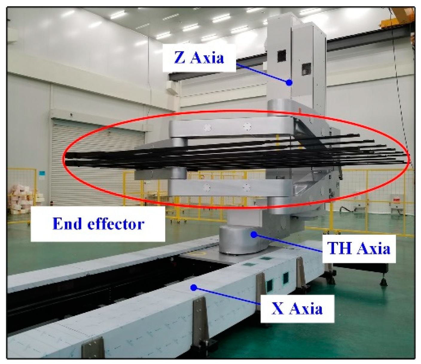
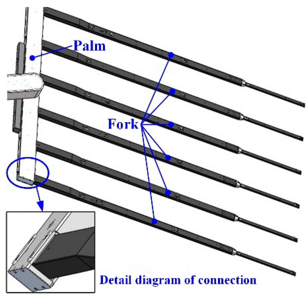
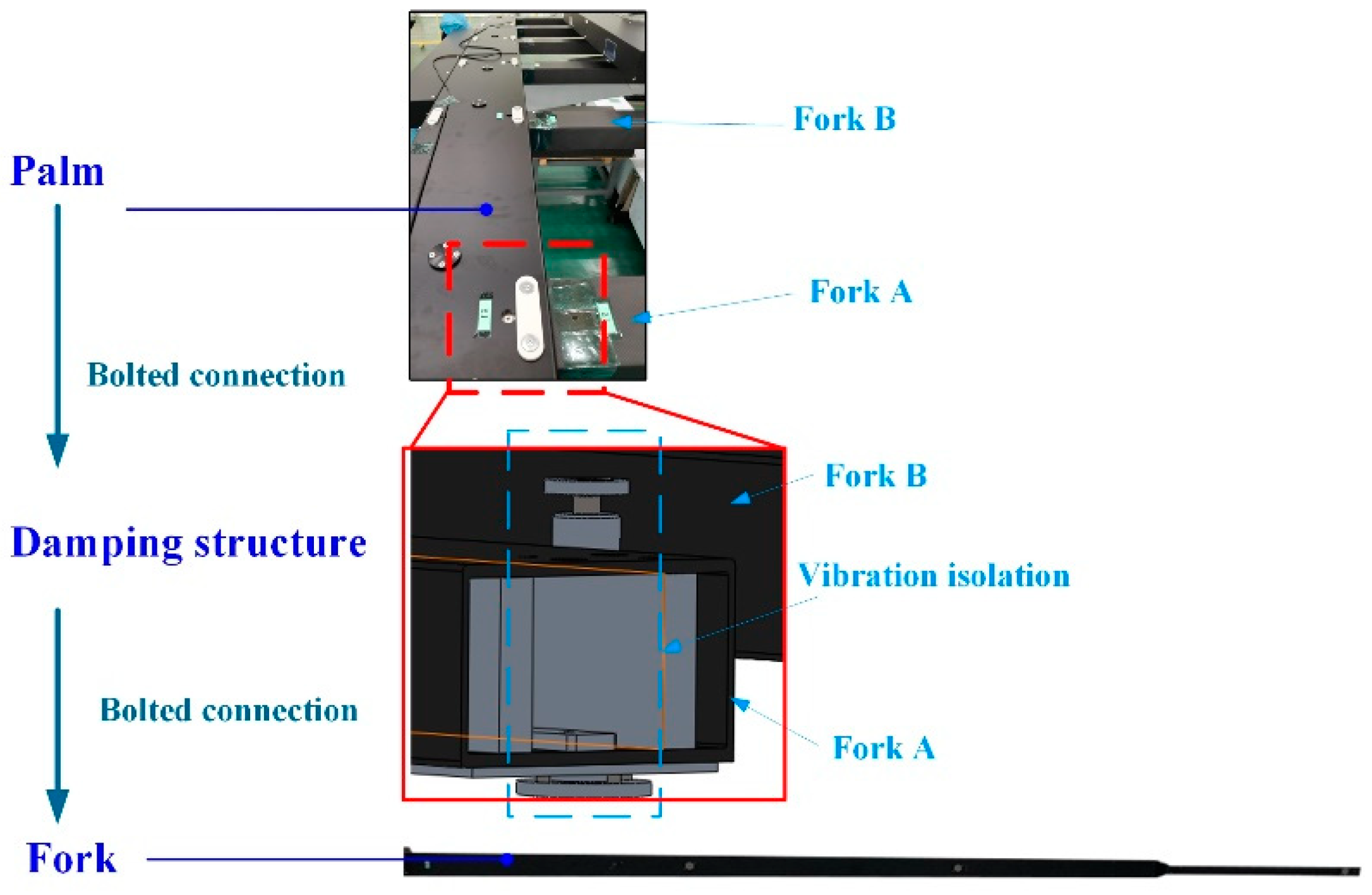
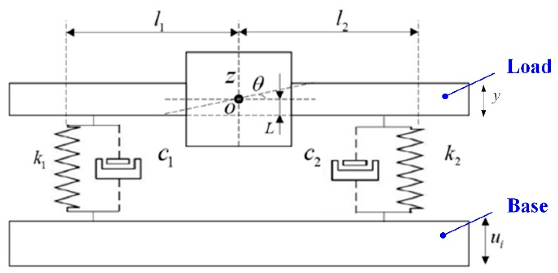
2. Simplified System of the Vibration Isolation System for the End Effector

The end effectors are the structures that directly contact the glass substrate and play the role of picking and placing the glass substrate for the glass substrate handling robot. However, due to the large scale and thinness of the glass substrate, the end effector is designed in the form of multiple interdigital combinations.
As shown in Figure 1, the body of the glass substrate handing robot contains X axia, TH axia, and Z axia to achieve movement in six directions. In addition, there are two end effectors to achieve the picking and placing of the glass substrate. Each end effector contains a palm that is the connection between six forks and the body of the robot, and the forks are shown in Figure 2. The vibration of the fork leads to the error of displacement between two forks, which leads to the fragments of the glass substrate. While picking the glass substrate, the palm forces the fork to move the glass. Each fork is connected to the palm through a damping structure, which is used to suppress the excitation from the robot body to the fork, so as to realize the vibration suppression as shown in Figure 3.
As shown in Figure 3, the fork and vibration isolation are located by the bolts on the palm, which means that, once there are some deviations of the bolts on the palm, there will be installation deviations for the forks. In addition, the performance parameters of the vibration isolator will also deviate because of the limitations of manufacturing and processing. These deviations will lead to different vibration isolation performances and cause the amplitude difference between the forks. Therefore, in order to realize the safety of picking and placing of the glass substrate, the influence of the parameter deviation of each vibration isolation structure on the vibration isolation performance of the system was quantitatively analyzed. To simplify the analysis, we randomly chose two interdigitated fingers, which is simplified as the load, and the palm was simplified as the base, so that the structure was simplified into a 2D freedom system. The 2D freedom vibration model of the VIS is shown in Figure 4.
The differential equation of the system is
m z ¨ + ( c 1 + c 2 ) z ˙ + ( c 1 l 1 + c 2 l 2 ) θ ˙ + ( k 1 + k 2 ) z + ( k 1 l 1 + k 2 l 2 ) θ = ( c 1 + c 2 ) u ˙ i + ( k 1 + k 2 ) u i
I 0 θ ¨ + ( c 1 l 1 + c 2 l 2 ) z ˙ + ( c 1 l 1 2 + c 2 l 2 2 ) θ ˙ + ( k 1 l 1 + k 2 l 2 ) z + ( k 1 l 1 2 + k 2 l 2 2 ) θ = ( c 1 l 1 + c 2 l 2 ) u ˙ i + ( k 1 l 1 + k 2 l 2 ) u i + m y ¨ L
where m is the mass of the end effector; I0 is the rotational inertia; k1, k2 is the rigidity of the vibration isolator; c1, c2 is the damping coefficient; l1, l2 is the distance from the vibration isolator to the center of mass; L is the distance from the center of mass to the vibration isolator; ui is the linear displacement of the end effector; y is the linear displacement through the vibration isolator; and z, θ are the linear displacement of the end effector on Z direction and the angular displacement around the center of mass.
The initial conditions are
z ( 0 ) = z ˙ ( 0 ) = 0 θ ( 0 ) = θ ˙ ( 0 ) = 0 u i ( 0 ) = u ˙ i ( 0 ) = 0 y ( 0 ) = y ˙ ( 0 ) = 0
Therefore, following the Laplace transform, Equations (1) and (2) are
[ m s 2 + ( c 1 + c 2 ) s + ( k 1 + k 2 ) ] Z ( s ) + [ ( c 1 l 1 + c 2 l 2 ) s + ( k 1 l 1 + k 2 l 2 ) ] θ ( s ) = [ ( c 1 + c 2 ) s + ( k 1 + k 2 ) ] U i ( s )
[ ( c 1 l 1 + c 2 l 2 ) s + ( k 1 l 1 + k 2 l 2 ) ] Z ( s ) + [ I 0 s 2 + ( c 1 l 2 + c 2 l 2 2 ) s + ( k 1 l 1 2 + k 2 l 1 2 ) ] θ ( s ) = [ ( c 1 l 1 + c 2 l 2 ) s + ( k 1 l 1 + k 2 l 2 ) ] U i ( s ) + m L s 2 Y ( s )
The nonlinear displacement in the Z direction is not considered; the transfer function of the system is
H z θ ( s ) = θ ( s ) U i ( s ) = A z ( s ) B ( s )
where A z ( s ) = m ( c 1 l 1 + c 2 l 2 ) s 3 + m ( k 1 l 1 + k 2 l 2 ) s 2 ,
B ( s ) = m I 0 s 4 + [ ( c 1 + c 2 ) I 0 + m ( c 1 l 1 2 + c 2 l 2 2 ) ] s 3 + [ m ( k 1 l 1 2 + k 2 l 2 2 ) + ( k 1 + k 2 ) I 0 + c 1 c 2 ( l 1 + l 2 ) 2 ] s 2 + ( k 1 c 2 + k 2 c 1 ) ( l 1 + l 2 ) 2 s + k 1 k 2 ( l 1 + l 2 ) 2
From Equation (6) it can be observed that, while the system satisfies k1l1 = k2l2 and c1l1 = c2l2, θ(s) ≡ 0, which means that the linear displacement of the end effector only causes the linear displacement of the fork along the Z direction without angular displacement. Therefore, the vibration isolation system of the fork is, respectively
ω n = k 1 + k 2 m ( c 1 + c 2 ) 2 4 m 2
The frequency expressions in Equation (7) contain the parameter of the installation span of two vibration isolators, which are discussed as follow.

3. Simulation Analysis of the Vibration System with Different Parameter Deviations

According to Equation (7), the deviations of the performance parameters affecting the vibration frequency of a single fork are stiffness and damping. However, for the whole end effector, there still exists a parameter deviation, which is the installation displacement of different vibration isolations.

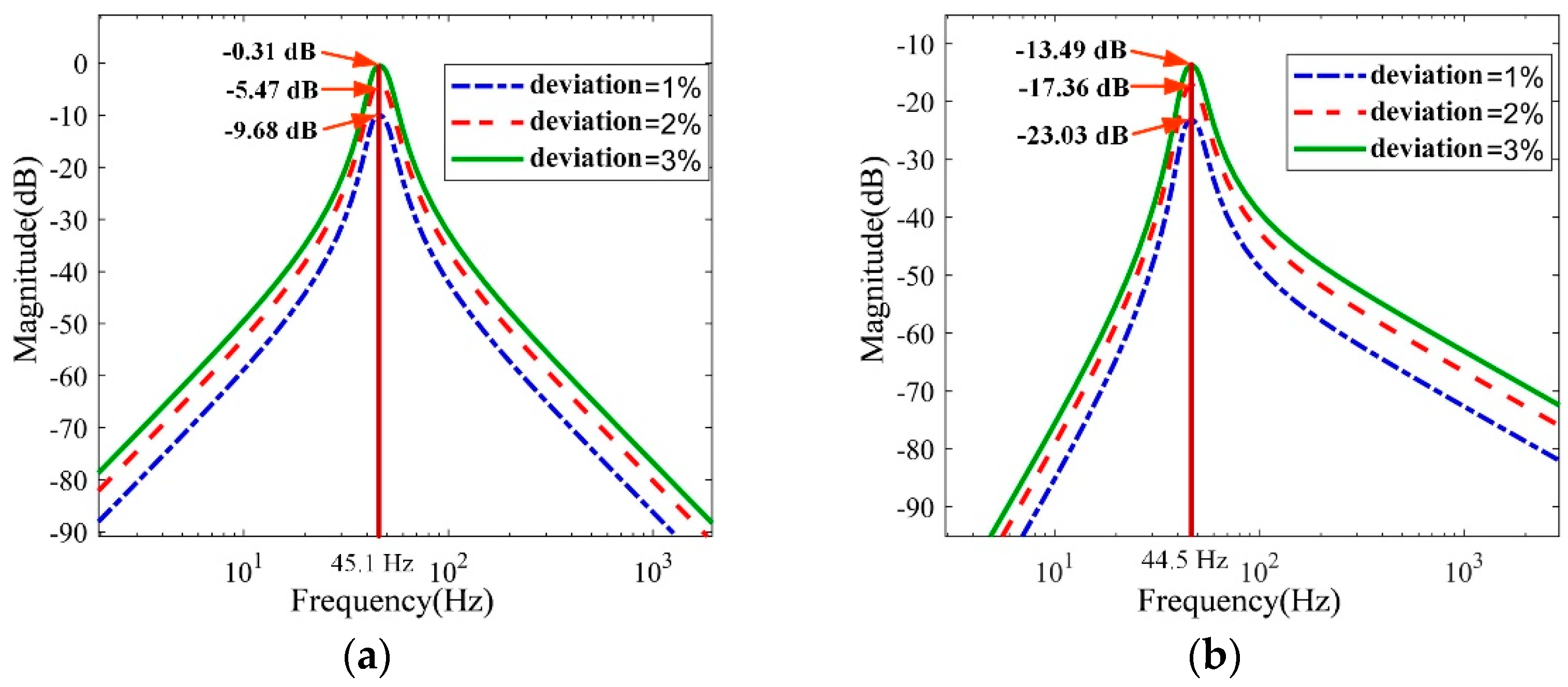
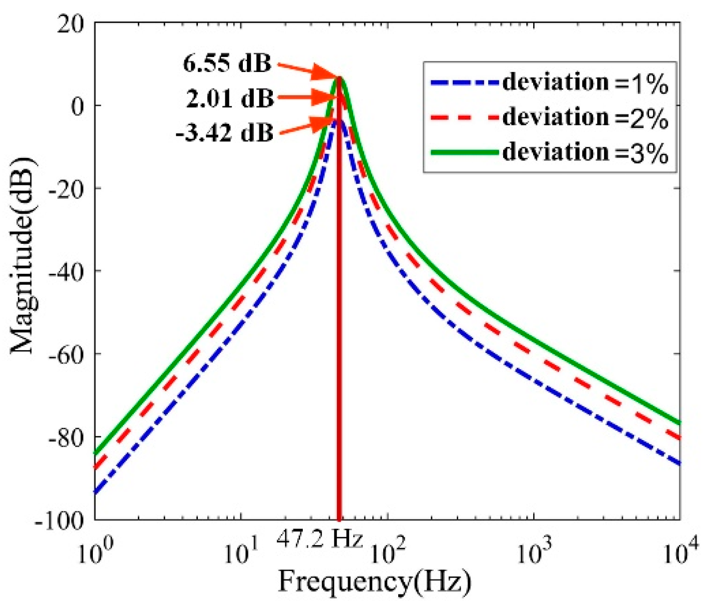
3.1. Influence of the Performance Parameter Deviation

Based on the deduced transfer function from the linear displacement of the palm to the linear displacement of the fork, this paper analyzes the influence of performance parameter deviation on the vibration isolation performance. The specific parameters of the simplified vibrations system are listed in Table 1.
The stiffness difference is
δ k = k 2 k 1 k 1
The damping difference is
δ c = c 2 c 1 c 1
According to Equation (6), the amplitude–frequency characteristic curves of the transfer function under different deviations are drawn as shown in Figure 5.
The “0 dB” means that the magnitude of the steady-state output is equal to the magnitude of the harmonic input. It can be found in Figure 5 that, when the performance parameters of the vibration isolator deviate, the resonant frequency of the system remains unchanged, and the transfer function increases first and then decreases with the frequency. However, as the deviation increases, the magnitude of the transfer function increases at each frequency. At the same time, the transmissibility at the resonance point is approximately proportional to the percentage of deviation. This shows that the vibration isolation effect of the system exists, but the closer it is to the resonant frequency of the system, the worse the vibration isolation performance of the system is.

3.2. Influence of the Distance Parameter Deviations between Two Vibration Isolations

According to the system above, this paper analyzes the influence of distance deviation between two vibration isolations, as shown in Figure 6.
It can be concluded that the resonance frequency and trend of the curve still remain unchanged with different distance deviations. However, compared to the curves of the performance parameter deviations, there is an obvious increase in the resonance frequency. According to the calculation formula of the transmissibility of the vibration isolation system, the transmissibility that is equivalent to the y axia is greater than 20 dB, which means that the acceleration is attenuated by 90%, and the acceleration of the passive side is only 0.1 times that of the active side. Therefore, we conclude that this vibration isolation device is considered to be a vibration isolation device that meets the requirements. In Figure 6, the range of the magnitude greater than 20 dB is much longer than Figure 5. This illustrated that the influence of the installation deviation is great and the VIS is invalid. This is the reason of the fragment for the robot handling.
Each palm was connected to six forks, which installed six vibration isolators. To scrutinize the distance deviation, this paper designed a two-degree-of-freedom simulation vibration isolation system, as shown in Figure 7. One third of the mass of the palm was simplified as the base and the two forks were simplified as the load. The base and the load were simplified into regular cuboids connected by two vibration isolators. The load block had the weight of 16 kg, which was the one third of the mass of the palm. Between both ends of the load, there were six mounting holes numbered from 1 to 6, which were used in different layouts for the vibration isolator. Each space of 2 adjacent holes was 25 mm, except for Holes 3 and 4. The distance between Holes 3 and 4 was 110 mm, and 6 holes were distributed symmetric of Point O. In the simulation system, the input channel was set at the barycenter of the lower base, and the output channel was set at the barycenter of the load block.

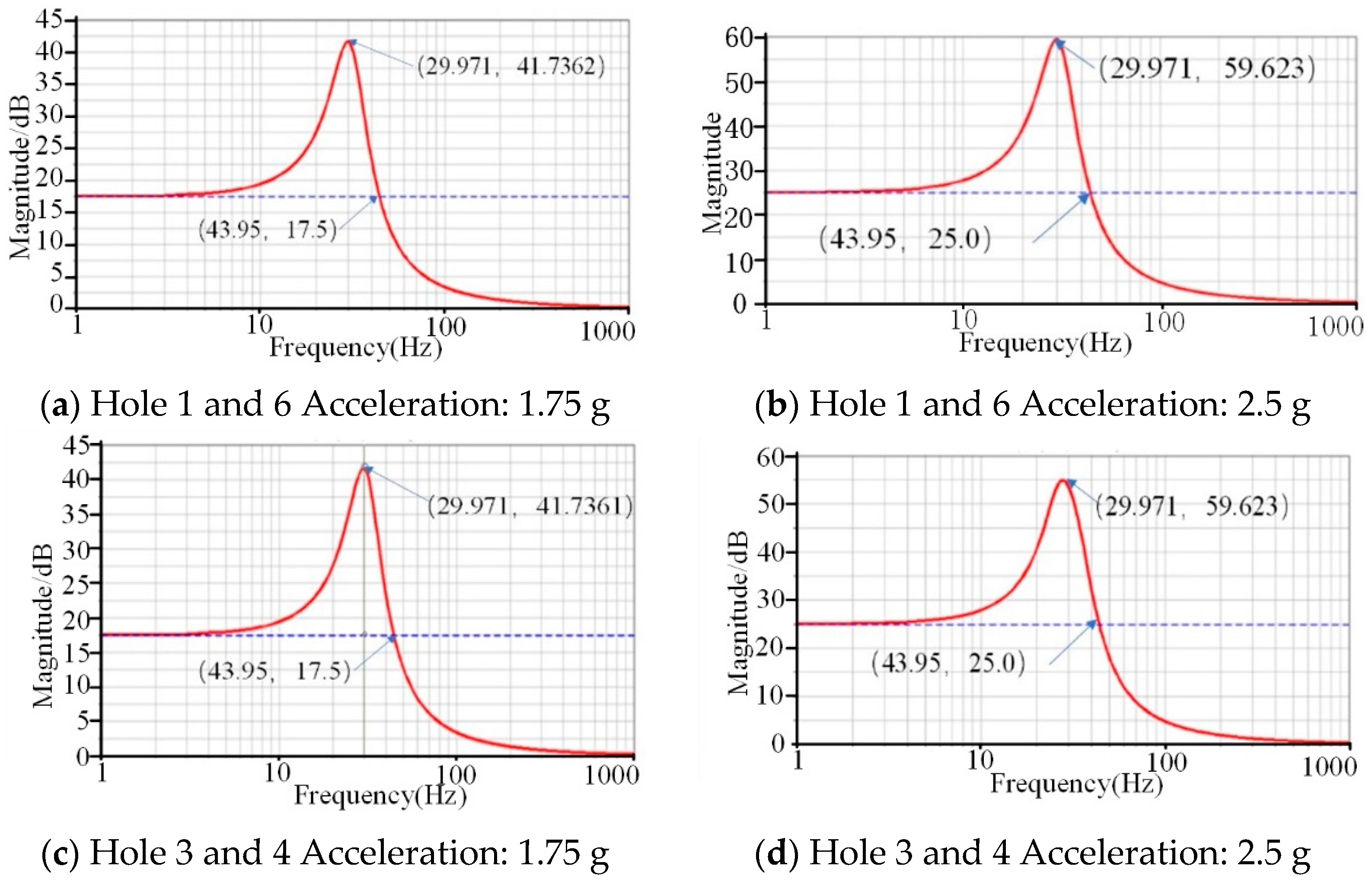
3.2.1. Symmetrical Distribution of the Vibration Isolators

Install two vibration isolators in Holes 1 and 6, and Holes 3 and 4 in sequence. This paper analyzed the frequency response of the system through applying a vertical sinusoidal frequency sweep acceleration signal with the magnitude of 1.75 g m/s2 or 2.5 g m/s2 and the frequency ranging from 1 to 1000 Hz. Additionally, the results are shown in Figure 8 and listed in Table 2.
According to the results above, we can conclude that the vibration characteristics remain unchanged, while the vibration isolator parameters are fixed. The natural frequency and the maximum magnification remain unchanged, while the distance and the external excitation change. The amplitude of resonance increases with the acceleration increase, regardless of the distance of two vibration isolations.

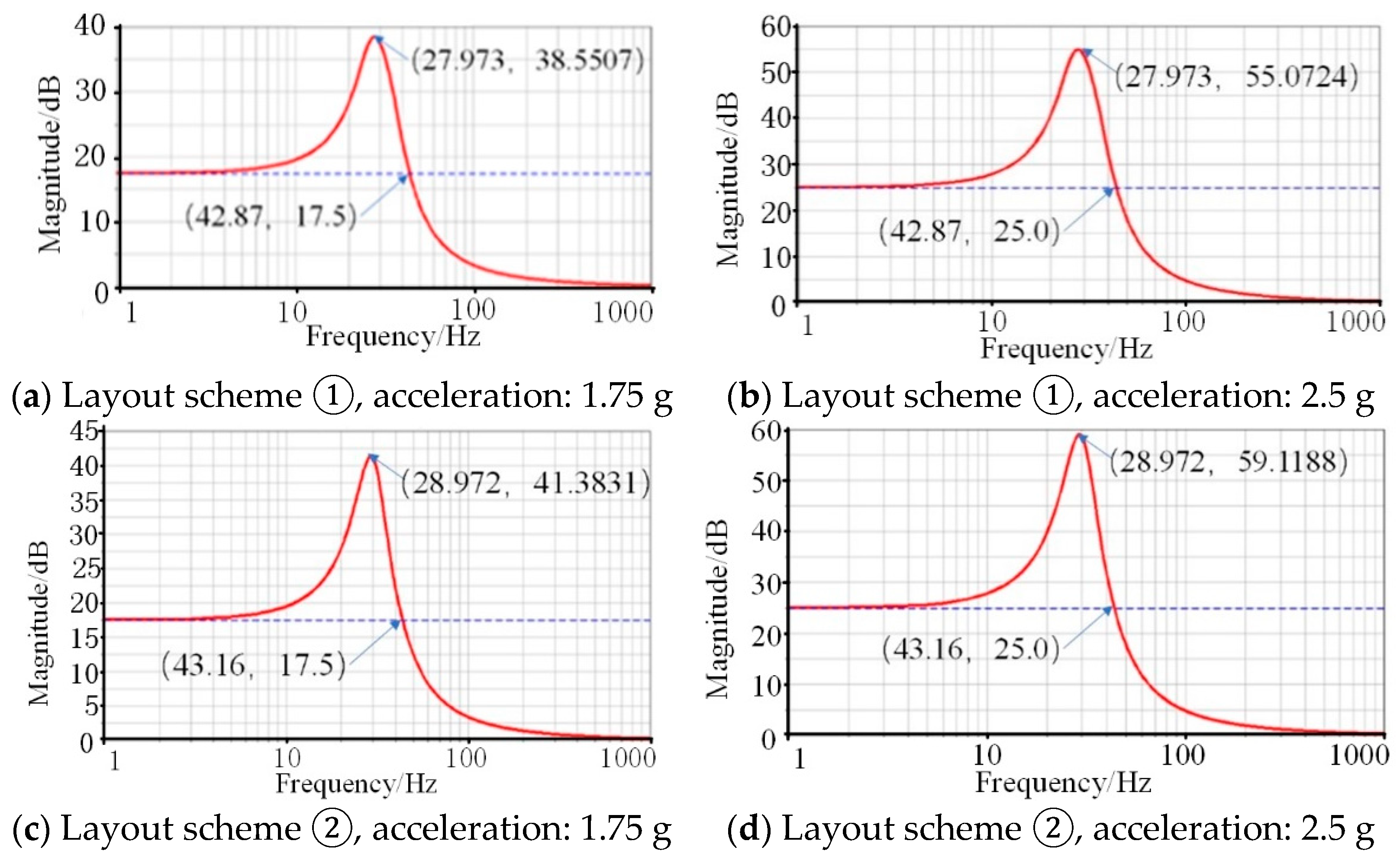
3.2.2. Asymmetric Distribution of the Vibration Isolators

To analyze the influence of the distance deviation between the two vibration isolators, the layout schemes of the vibration isolation system were designed. This study designed two different installations of the vibration isolations. In layout scheme ①, the vibration isolators are located in Holes 1 and 5. In layout scheme ②, the vibration isolators are located in Holes 2 and 4, as shown in Figure 7. It is obvious that the distance deviation of the vibration isolators in layout scheme ① is less than that in layout scheme ②. The frequency-response simulation analysis of the simulated vibration isolation system under different layout forms was conducted, and the analysis results are listed in Table 3 and the curves are shown in Figure 9.
According to the results above, the deviations in the distance change the natural frequency under the same excitation accelerations. In addition, the amplitude of resonance relates to the deviation and the excitation acceleration. With the increase in the acceleration, the amplitude increases.
In summary, the parameters of the vibration isolator set in the simulation analysis process remain unchanged, and the vibration characteristics of the vibration isolation system are fixed. Therefore, the natural frequency and resonance magnification of the system will not change with the change of external excitation. Due to the asymmetric arrangement of the vibration isolators in the system, the excitation is eccentric and leads to vibration coupling, which reduces the vibration isolation performance of the system. The vibration isolation performance decreases with the increase in the distance deviation.

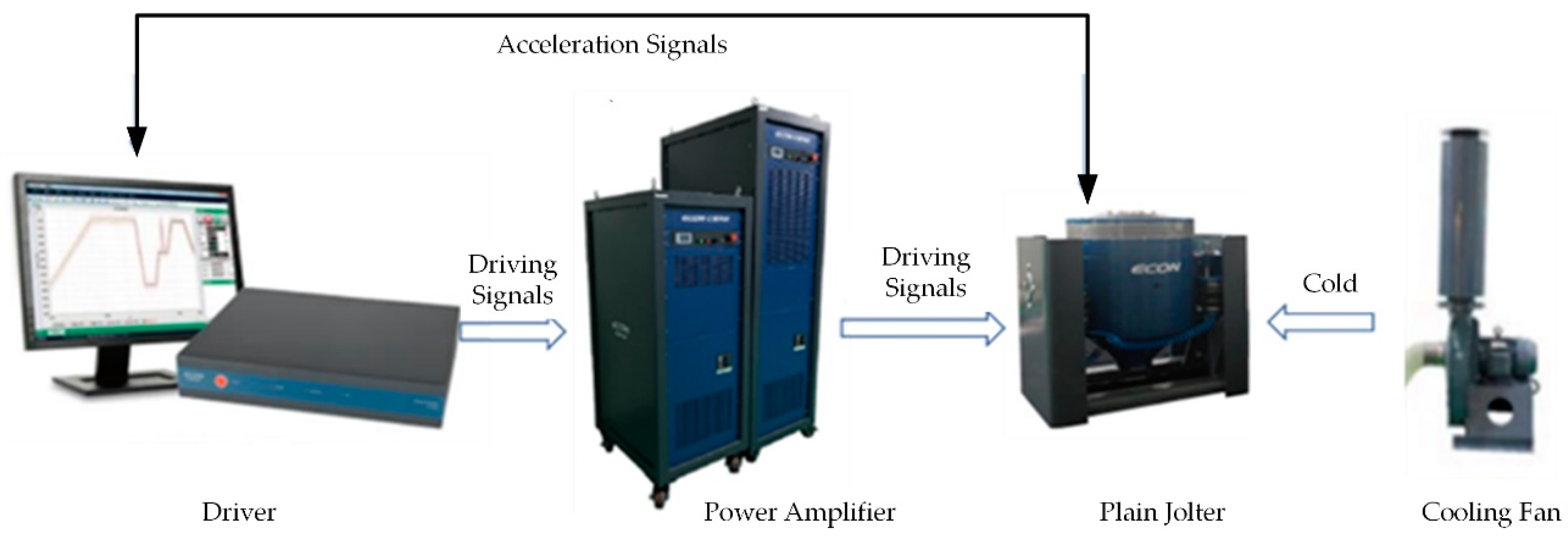
4. Experimental Analysis

To explore the influence of installation deviations on the vibration isolation performance of the system, we designed the dynamic frequency sweeping system. Additionally, the diagram of the dynamic frequency sweeping system of a plain jolter is shown in Figure 10. Additionally, the experiment table is set up as shown in Figure 11.
We randomly selected two forks and used their mass as the simulation load that is 16 kg, and each fork is connected with a vibration isolation, so that the 16 kg cuboid lead block was used to simulate the load and two vibration isolators were installed on the vibration test bench. Two acceleration sensors were installed on the vibration test bench and the load, which were used to collect two acceleration signals at the same time; one was the excitation signal and the other was the vibration isolation signal. The base was the simulation of the palm that was treated as the excitation source. In the experiment, the excitation signal started at 1 Hz with a constant acceleration and swept to 1000 Hz that simulated the actual excitation signal.

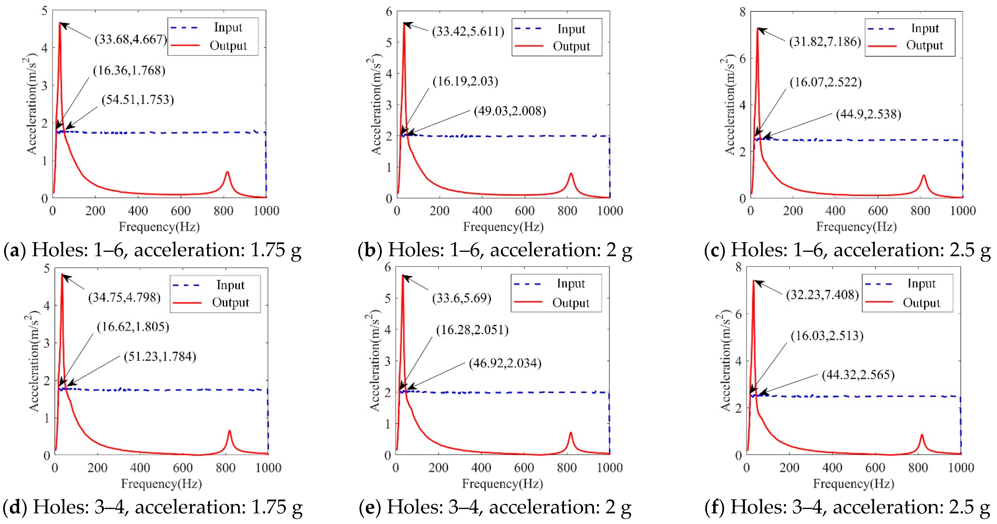
4.1. Dynamic Frequency Sweep Experiment of Symmetrically Arranged Vibration Isolators

The load remained at 16 kg. The distance between the two vibration isolations was 110 mm (the two vibration isolations are installed as Holes 1 and 6) and 210 mm (the two vibration isolations are installed as Holes 3 and 4). The acceleration was 1.75 g m/s2, 2 g m/s2, and 2.5 g m/s2, respectively. Through the vibration frequency sweeping experiment, the acceleration experimental curves of the frequency sweeping input and vibration isolation output were obtained, as shown in Figure 12.
From the analysis of the results as listed in Table 4, it can be concluded that the natural frequency remains stable, no matter the degree of acceleration. Additionally, the second-order resonance frequency was 830 Hz, and this was consistent with the characteristics of the 2D freedom system. The increase in the distance between the vibration isolators also made the system more stable during resonance, so its resonance magnification was slightly smaller.

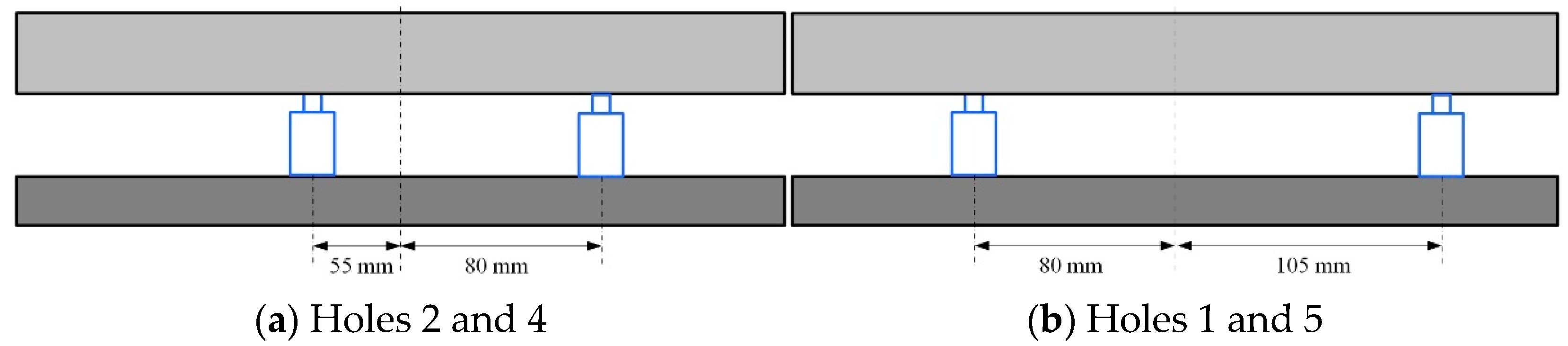
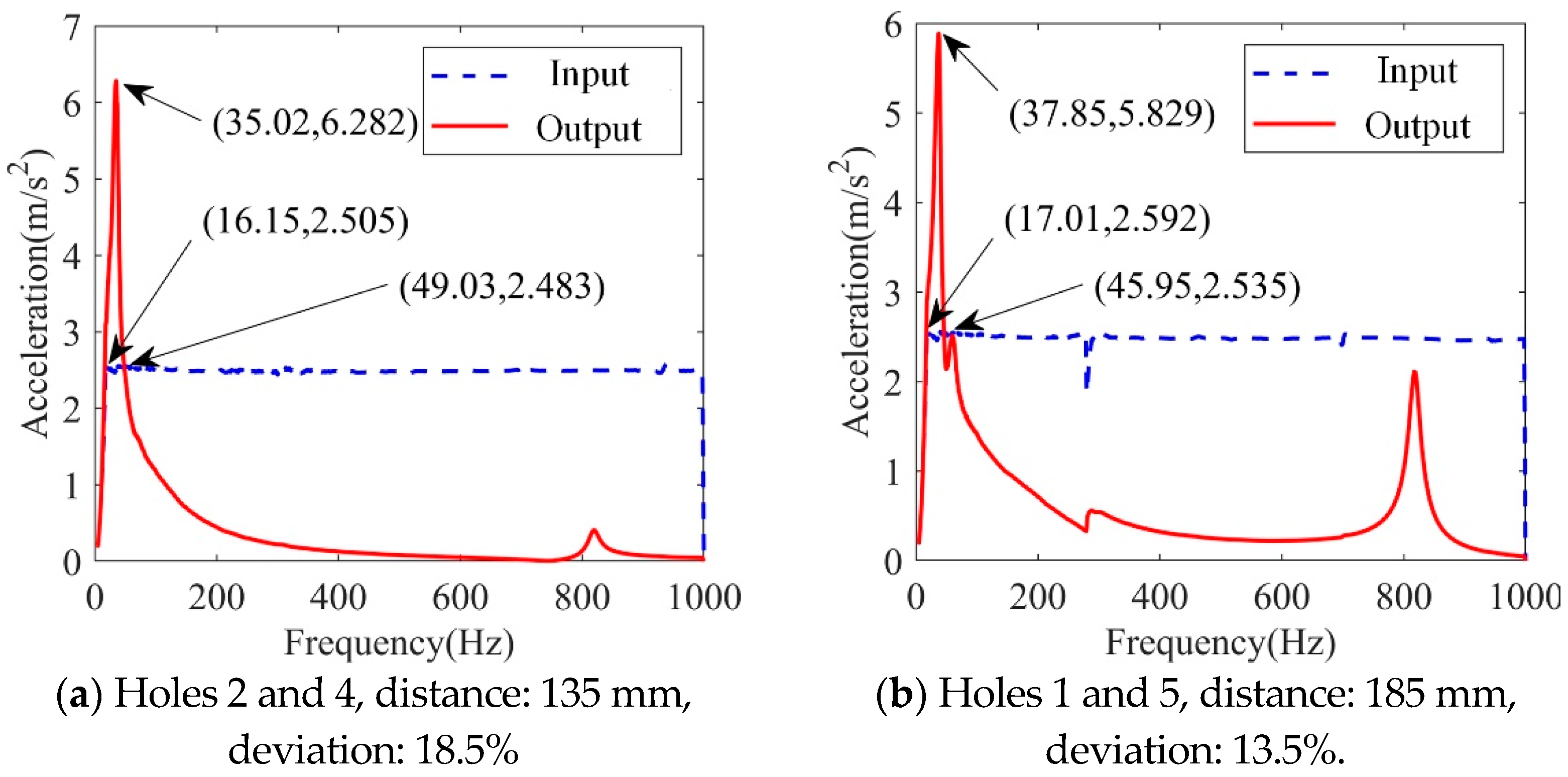
4.2. Dynamic Frequency Sweep Experiment of Asymmetrically Arranged Vibration Isolators

The spacing difference is
δ l = l 2 l 1 l 1 + l 2
The mass of the load remained at 16 kg. The distance of the two vibration isolations was 135 mm while installed in Holes 1 and 5. The distance was 185 mm while installed in Holes 2 and 4, respectively. According to the results, the difference was maximum value, while the acceleration was 2.5 g m/s2. Therefore, the acceleration was set as 2.5 g m/s2.
As shown in Figure 13a, the spacing is 135 mm and the deviation is
δ l 1 = l 2 l 1 l 1 + l 2 = 80 55 55 + 80 = 25 135 18.5 %
As shown in Figure 13b, the spacing is 185 mm and the deviation is
δ l 2 = l 2 l 1 l 1 + l 2 = 105 80 80 + 05 = 25 185 13.5 %
The experimental curves of the dynamic frequency sweep for the vibration isolation systems with different distance deviations are shown in Figure 14.
According to the experiment data, the resonant amplitude increases when the distance deviation increases. Additionally, the start frequency of the vibration isolation changes from 49.03 Hz to 45.95 Hz, which means that the effective vibration isolation decreases. Therefore, the smaller the distance deviation, the better the vibration isolation performance of the system.

5. Discussion and Conclusions

5.1. The Discussion of the Experiment

We summarized and compared the experimental results and the comparisons of the vibration isolation performances are listed in Table 5, while the excitation remains 2.5 g m/s2.
Analyzing the data in Table 5, we can easily conclude that the installation distance of the vibration isolations for the 2D vibration system didn’t influence the natural frequency while the installation is symmetrical. Here, the differences in the maximum magnification values was due to the inconformity of the structural parameters for two vibration isolations. As a consequence, the more similar the performance parameters of the vibration isolator and the lower the deviation of the installation spacing, the better the vibration isolation performance.
In addition, while the deviation was 13.5%, the natural frequency increased (37.85 − 31.82)/31.82 = 18.9%, and the maximum magnification increased (5.83 − 2.96)/2.96 = 97%. While the deviation was 18.5%, the natural frequency increased (35.02 − 31.82)/31.82 = 10%, and the maximum magnification increased (6.28 − 2.88)/2.88 = 118%.
With the same excitation, the deviation increased, the deviation of the natural frequency decreased, and the maximum magnification increased. When the vibration isolator had a performance parameter deviation and installation position deviation, it lead to an increase in the resonance amplitude value and an increase in the initial frequency of the vibration isolation.
For the interdigital fingers of the end effector of the handling robot, during the process of picking up the glass substrate, the excitation signal of the palm to the fork could be regarded as a constant. However, due to the deviation of the performance parameters or installation distance of any two vibration isolators, the response characteristics of the two fork-forced vibrations were inconsistent, and there were phase differences and amplitude differences, resulting in glass substrate fragments. This explains why debris could still be generated after installing an isolator with a satisfactory isolation performance. To achieve the safety pick-and-place for the glass substance, we should experiment and choose six vibration isolations that have the most similar performance parameters. The length of the palm was 2897 mm. Therefore, the installation spacing between the forks should be 579.4 mm and remain unchanged at all times.

5.2. Conclusions

This study complemented the causes of poor vibration isolation system performance and provided guidance for the design and installation of vibration isolators in mechanical systems and vibration suppression systems. To guide the multi-degree-of-freedom system, the deviation of the performance parameters and installation parameters of the vibration isolator will reduce the vibration isolation frequency range and isolation amplitude value. Subsequent research can conduct in-depth research from the perspective of the precise control of deviations, such as deviation transfer and optimization algorithms.

Author Contributions

All the authors have made great contributions to the design of the system. H.S. designed and processed the structure, performed the experiment, analyzed the data, and wrote the paper. X.S. supervised the article and the experiment. H.Y. finished the experimental measurements and the analysis of the data. G.W. and J.F. dedicated their valuable suggestions and comments on the interpretation of the results and on the paper. All authors have read and agreed to the published version of the manuscript.

Funding

This work was supported by the National Key R&D Program of China, Grant No. 2018YFB1308500 and HIT WuHu Robot Technology Research Institute, Grant No. HIT-CXY-CMP2-VSEA-21-01.

Institutional Review Board Statement

Not applicable.

Informed Consent Statement

Not applicable.

Data Availability Statement

Not applicable.

Conflicts of Interest

The authors declare no conflict of interest.

References

  1. Pan, X.; Lu, J.; Huo, J.; Gao, J.; Wu, H. A Review on Self-Recovery Regulation (SR) Technique for Unbalance Vibration of High-End Equipment. Chin. J. Mech. Eng. 2020, 33, 89. [Google Scholar] [CrossRef]
  2. Yu, H.; Yan, X. Principle and Application of Free Resonance Vibration Isolation Based on Dry Friction Damper. In Proceedings of the 2nd International Conference on Functional Manufacturing and Mechanical Dynamics, Hangzhou, China, 22–25 January 2012; p. 59. [Google Scholar]
  3. Hou, J.F.; Li, R.L.; Yu, G.C.; Luo, T.; He, H.W. Contrast Test Research on Application of Dry Friction Isolators to Vibration Isolation of Vehicle Electronic Devices. Appl. Mech. Mater. 2014, 505, 360–364. [Google Scholar] [CrossRef]
  4. Qu, D.; Liu, X.; Liu, G.; Bai, Y.; He, T. Analysis of vibration isolation performance of parallel air spring system for precision equipment transportation. Meas. Control 2019, 52, 291–302. [Google Scholar] [CrossRef] [Green Version]
  5. Bednarz, J. The New Methodology for Assessing of the Applicability of Elastomeric Materials in the Vibration Isolation Systems of Railway Lines. Arch. Acoust. 2016, 41, 573–578. [Google Scholar] [CrossRef] [Green Version]
  6. Jia, D.; Pang, F.-z.; Yin, X.-c.; Ye, X. Study on the vibro-acoustic characteristics of a vibration isolation mass structure with composite braces. In Proceedings of the International Conference on Applied Mechanics, Materials and Manufacturing (ICAMMM 2011), Shenzhen, China, 18–20 November 2012; p. 85. [Google Scholar]
  7. Bazinenkov, A.M.; Ivanova, D.A.; Efimov, I.A.; Rotar, A.P. Research of the mechanical properties of a magnetorheological elastomer for an active vibration isolation system. Vestn. Mashinostroeniya 2021, 41, 60–64. [Google Scholar] [CrossRef]
  8. Yarra, S.; Gordaninejad, F.; Behrooz, M.; Pekcan, G.; Itani, A.M.; Publicover, N. Performance of a large-scale magnetorheological elastomer-based vibration isolator for highway bridges. J. Intell. Mater. Syst. Struct. 2018, 29, 3890–3901. [Google Scholar] [CrossRef]
  9. Brancati, R.; Di Massa, G.; Pagano, S.; Petrillo, A.; Santini, S. A combined neural network and model predictive control approach for ball transfer unit-magnetorheological elastomer-based vibration isolation of lightweight structures. J. Vib. Control 2020, 26, 1668–1682. [Google Scholar] [CrossRef]
  10. Lu, Z.Q.; Zhao, L.; Ding, H.; Chen, L.Q. A dual-functional metamaterial for integrated vibration isolation and energy harvesting. J. Sound Vib. 2021, 509, 116251. [Google Scholar] [CrossRef]
  11. Hu, G.B.; Austin, A.C.M.; Sorokin, V.; Tang, L.H. Metamaterial beam with graded local resonators for broadband vibration suppression. Mech. Syst. Signal Process. 2021, 146, 106982. [Google Scholar] [CrossRef]
  12. Stearns, A.; Beck, B. An optimization problem for maximum vibration suppression in reconfigurable one dimensional metamaterials. New J. Phys. 2021, 23. [Google Scholar] [CrossRef]
  13. Perez-Aracil, J.; Pereira, E.; Aphale, S.S.; Reynolds, P. Vibration Isolation and Alignment of Multiple Platforms on a Non-Rigid Supporting Structure. Actuators 2020, 9, 108. [Google Scholar] [CrossRef]
  14. Zhang, Y.; Fang, B.; Chen, Y.; Wang, L. Performance Analysis of Discrete Whole-Spacecraft Vibration Isolation Platforms for Flexible Spacecrafts. In Proceedings of the Conference on Active and Passive Smart Structures and Integrated Systems, San Diego, CA, USA, 8–11 March 2010. [Google Scholar]
  15. Hua, Y.L.; Jun, L.J.; Jian, Z.S. Researches on Nonlinear Hybrid Vibration Isolation System. In Proceedings of the 4th International Conference on Computing, Control and Industrial Engineering (CCIE 2013), Wuhan, China, 27–28 October 2013; pp. 222–227. [Google Scholar]
  16. Garcia-Perez, O.A.; Silva-Navarro, G.; Peza-Solis, J.F. Flexible-Link Robots with Combined Trajectory Tracking and Vibration Control. Appl. Math. Model. 2019, 70, 285–298. [Google Scholar] [CrossRef]
  17. Barjuei, E.S.; Boscariol, P.; Vidoni, R. Robust Control of Three-Dimensional Compliant Mechanisms. ASME J. Dyn. Sys. Meas. Control 2016, 10, 138. [Google Scholar] [CrossRef]
  18. Zhang, G.; Pang, H.; He, J. Selection and Optimization in Vibration Isolation Structure of Marine Podded SSP Propulsion. In Proceedings of the 4th International Conference on Measuring Technology and Mechatronics Automation (ICMTMA 2012), Sanya, China, 6–7 January 2012; p. 280. [Google Scholar]
  19. Sohail, A.; Liu, C. Study on the vibration isolation characteristics of an anti-resonant hydropneumatic suspension. J. Eng. 2019, 13, 208–210. [Google Scholar] [CrossRef]
  20. Wang, J. Active vibration control: Design towards performance limit. Mech. Syst. Signal Processing 2022, 171, 108926. [Google Scholar] [CrossRef]
  21. Zhu, L.; Yuan, H.; Zhou, H.; Jiang, D.; Liu, B.; Fan, C.; Tang, L. Vibration Test and Shock Absorption of Coal Crusher Chambers in Thermal Power Plants (I): Field Test and Assessment. Shock Vib. 2020, 2020, 8816829. [Google Scholar] [CrossRef]
  22. Eem, S.; Kim, J.H. Sensitivity analysis for the distribution of maximum responses by seismic isolation system parameters using the stochastic response database. Nucl. Eng. Des. 2019, 347, 53–58. [Google Scholar] [CrossRef]
  23. Alhan, C.; Hisman, K. Seismic isolation performance sensitivity to potential deviations from design values. Smart Struct. Syst. 2016, 18, 293–315. [Google Scholar] [CrossRef]
  24. Gazi, H.; Alhan, C. Reliability of elastomeric-isolated buildings under historical earthquakes with/without forward-directivity effects. Eng. Struct. 2019, 195, 490–507. [Google Scholar] [CrossRef]
  25. Qian, Z.J.; Cao, M.G.; Ying, J.L.; Zhuang, W.D.; Zhang, H.; Shi, J.; Zhou, D.C. Vibration characteristics and vibration isolation design of oil-immersed power transformer. In Proceedings of the 2nd International Conference on Civil Engineering, Environment Resources and Energy Materials, Changsha, China, 18–20 September 2020. [Google Scholar]
  26. Lu, Z.Q.; Gu, D.H.; Ding, H.; Lacarbonara, W.; Chen, L.Q. Nonlinear vibration isolation via a circular ring. Mech. Syst. Signal Process. 2019, 136, 106490. [Google Scholar] [CrossRef]
  27. Tan, D.; Lu, Z.Q.; Gu, D.H.; Ding, H.; Chen, L.Q. A Ring Vibration Isolator Enhanced by a Nonlinear Energy Sink. J. Sound Vib. 2021, 508, 116201. [Google Scholar] [CrossRef]
  28. Li, Z.; Wu, Q.; Liu, B.; Gong, Z. Optimal Design of Magneto-Force-Thermal Parameters for Electromagnetic Actuators with Halbach Array. Actuators 2021, 10, 231. [Google Scholar] [CrossRef]
  29. Rossi, A.; Orsini, F.; Scorza, A.; Botta, F.; Belfiore, N.P.; Sciuto, S.A. A Review on Parametric Dynamic Models of Magnetorheological Dampers and Their Characterization Methods. Actuators 2018, 7, 16. [Google Scholar] [CrossRef] [Green Version]
  30. Markou, A.A.; Stefanou, G.; Manolis, G.D. Stochastic energy measures for hybrid base isolation systems. Soil Dyn. Earthq. Eng. 2019, 119, 454–470. [Google Scholar] [CrossRef]
  31. Hu, Y.Q.; Feng, Z.W.; Qin, J.; Yang, F.; Zhao, J. Design and Verification of Micro-Vibration Isolator for a CMG. In Proceedings of the 5th International Symposium of Space Optical Instruments and Applications, Sino Holland Space Opt Instruments Joint Lab, Beijing, China, 5–7 September 2018; pp. 281–286. [Google Scholar]
  32. Zhou, Y.; Chen, P. Investigations on a vertical isolation system with quasi-zero stiffness property. Smart Struct. Syst. 2020, 25, 543–557. [Google Scholar] [CrossRef]
  33. Anvar, V. Numerical and Experimental Analysis of Metamaterials With Quasi-Zero Effect for Vibration Isolation. In Proceedings of the International Conference on Functional Materials, Characterization, Solid State Physics, Power, Thermal and Combustion Energy (FCSPTC), Andhra Pradesh, India, 7–8 April 2017. [Google Scholar]
  34. Demir, M.U.; Yilmaz, C. Analysis and design of an adjustable stiffness three-axis horizontal vibration isolator using elastic columns and a string in tension. J. Sound Vib. 2022, 523, 116736. [Google Scholar] [CrossRef]
  35. Bian, J.; Jing, X. Analysis and design of a novel and compact X-structured vibration isolation mount (X-Mount) with wider quasi-zero-stiffness range. Nonlinear Dyn. 2020, 101, 2195–2222. [Google Scholar] [CrossRef]
  36. Jiang, Y.; Song, C.; Ding, C.; Xu, B. Design of magnetic-air hybrid quasi-zero stiffness vibration isolation system. J. Sound Vib. 2020, 477, 115346. [Google Scholar] [CrossRef]
  37. Lee, D.H.; Kim, Y.B.; Chakir, S.; Huynh, T.; Park, H.C. Noninteracting Control Design for 6-DoF Active Vibration Isolation Table with LMI Approach. Appl. Sci. 2021, 11, 7693. [Google Scholar] [CrossRef]
  38. Ito, S.; Lindner, B.; Schitter, G. Sample-tracking Vibration Isolation with Hybrid Reluctance Actuators for Inline Metrology. IFAC PapersOnLine 2019, 52, 537–542. [Google Scholar] [CrossRef]
  39. Yu, X.; Cong, W.; Yu, Z.; Tomizuka, M. Controller design and optimal tuning of a wafer handling robot. In Proceedings of the IEEE International Conference on Automation Science & Engineering, Mexico City, Mexico, 20–24 August 2022. [Google Scholar]
Figure 1. The construction of the glass substrate handling robot.
Actuators 11 00133 g001
Figure 2. The construction of the end effector.
Actuators 11 00133 g002
Figure 3. The details of the connection.
Actuators 11 00133 g003
Figure 4. Schematic diagram of freedom model for the 2D vibration isolation system.
Actuators 11 00133 g004
Figure 5. Amplitude-frequency curves of transfer functions with different parameter deviations. (a) Different stiffness deviations; (b) Different damping deviations.
Actuators 11 00133 g005
Figure 6. Amplitude-frequency curves of transfer functions with distance deviations.
Actuators 11 00133 g006
Figure 7. Dynamic model of 2D freedom vibration isolation system. (a) The structure graphic of the end effector; (b) The equivalent simplified structure graphic of the end effector.
Actuators 11 00133 g007
Figure 8. The frequency response curve of the symmetrical distribution of vibration isolators.
Actuators 11 00133 g008
Figure 9. The frequency-response curve of the asymmetric distribution of vibration isolators.
Actuators 11 00133 g009
Figure 10. The dynamic frequency sweeping system of the plain jolter.
Actuators 11 00133 g010
Figure 11. Dynamic frequency sweep experiment diagram. (a) The structure graphic of the end effector; (b) The equivalent simplified structure graphic of the end effector.
Actuators 11 00133 g011
Figure 12. Dynamic sweep frequency experimental curves of 2D freedom vibration isolation systems with different distances.
Actuators 11 00133 g012
Figure 13. Schematic diagram of the different deviations.
Actuators 11 00133 g013
Figure 14. Experimental curves of the dynamic frequency sweep for vibration isolation systems with different distances.
Actuators 11 00133 g014
Table 1. Parameters of the vibration isolation system of the end effector.
ParametermI0k1, k2c1, c2l1, l2
Numerical value160.778920,00095.06570.19
Table 2. Frequency-response results.
PositionAcceleration/m/s2Natural Frequency/HzAmplitude of ResonanceMaximum Magnification
Holes 1 and 61.75 g29.9741.742.38
Holes 1 and 62.5 g29.9759.622.38
Holes 3 and 41.75 g29.9741.742.38
Holes 3 and 42.5 g29.9759.622.38
Table 3. Frequency-response results.
PositionAcceleration/m/s2Natural Frequency/HzAmplitude of ResonanceMaximum Magnification
Holes 1 and 51.75 g27.9738.552.20
Holes 1 and 52.5 g27.9755.072.20
Holes 2 and 41.75 g28.9741.382.36
Holes 2 and 42.5 g28.9759.122.36
Table 4. Experimental results of the dynamic frequency sweep of vibration isolators with different distances.
PositionAcceleration/m/s2Natural Frequency/HzMaximum Magnification
Holes 1 and 61.75 g33.682.67
Holes 1 and 62 g33.422.81
Holes 1 and 62.5 g31.822.88
Holes 3 and 41.75 g34.752.74
Holes 3 and 42 g33.602.85
Holes 3 and 42.5 g32.232.96
Table 5. Influence of deviation on vibration isolation performance.
PositionAcceleration/ m/s2Natural Frequency/HzMaximum MagnificationDeviation
Holes 1 and 62.5 g31.822.960
Holes 1 and 52.5 g37.855.8313.5%
Holes 3 and 42.5 g31.822.880
Holes 2 and 42.5 g35.026.2818.5%
Publisher’s Note: MDPI stays neutral with regard to jurisdictional claims in published maps and institutional affiliations.

