Article

Performance-Optimized Dielectric Elastomer Actuator System with Scalable Scissor Linkage Transmission

by
Daniel Bruch
1,*,
Tobias Pascal Willian
1,
Hendrik Cornelius Schäfer
2 and
Paul Motzki
1,2
1
iMSL—Intelligent Material Systems Laboratory, Saarland University, 66121 Saarbrücken, Germany
2
ZeMA—Center for Mechatronics and Automation Technology, 66121 Saarbrücken, Germany
*
Author to whom correspondence should be addressed.
Actuators 2022, 11(6), 160; https://doi.org/10.3390/act11060160
Submission received: 6 April 2022 / Revised: 25 April 2022 / Accepted: 26 April 2022 / Published: 14 June 2022
(This article belongs to the Special Issue Smart Dielectric Elastomer Actuator and Sensor Systems)

Abstract

:
Thanks to their outstanding properties, in the last few years Dielectric Elastomer Actuators (DEAs) have increasingly attracted the interest of the scientific community and generated a surge in the effort devoted to their industrialization. Compared to conventional actuator systems, DEAs are based on inexpensive and widely available polymeric materials, which make them potentially attractive from a market perspective. However, DEA systems with a given layout and dimensions have a fixed force-stroke response that is only suitable for a specific load profile. This leads to a wide variety of designs combined with small production volumes and high costs, limiting the competitive advantage. This work addresses this issue by proposing a combination of DEA systems with compliant scissor linkage transmission mechanisms, which provide linear stroke and force scaling and simultaneously maintain performance optimization by leaving the convertible energy density of the DEA unaffected. For this purpose, three systems are designed, based on a same strip-shaped DEA combined with inclined buckled beam biasing mechanisms. Two of the systems are coupled with scissor linkages that offer transmission ratios of 3:1 and 1:3, respectively, to adapt the system to different load profiles. The system design is explained in detail, and the functional principle is validated through experiments.

1. Introduction

Dielectric Elastomer Actuators (DEAs) consist of highly stretchable dielectric polymers, which are sandwiched in between two flexible and conductive electrodes. Structure, principle of operation, possible materials of use, and first applications for DEAs have already been defined and scientifically formulated at the beginning of the 21st century [1,2,3]. Since then, DEAs have been further developed with a focus on different fields such as materials, design, and manufacturing. Commonly used dielectric polymers are natural or synthetic rubber [4], silicone [5], and acrylic films [4,6]. They are provided with thin stretchable electrodes e.g., made of carbon-loaded polymeric layers [7,8] or metal thin films [7,9] using different manufacturing processes such as screen printing [10], spray coating [11], or sputtering [12]. The basic structure of an inactive DEA is given in Figure 1. In the inactive state, shown on the left, no voltage is applied to the electrodes and the DEA lies in its undeformed configuration. By applying a (high) electric voltage to the electrodes (Figure 1 right), an electric field is induced in the dielectric. This causes electro-static coulomb forces (namely, Maxwell stress), which lead to a reduction in thickness and an increase in the surface area of the dielectric. Both effects can be used to make work against external loads, with surface expansion better suited to realize large strokes with scalable force by stacking several layers. Since DEAs are variable capacitors, by measuring the capacitance changes associated with their deformations, information about their current configuration can be derived and used to develop sensing devices [13]. By monitoring the capacitance during actuation, conclusions can be drawn about the actual material strain and thus the position of the DEA. This enables the development of intelligent (smart) actuation systems, which can be operated in a closed control loop without any additional external sensor (self-sensing) [14]. Thanks to their electrostatic operating principle, DEAs can hold their current configuration with little energy loss in static conditions. This makes them particularly suited to applications in the field of soft robotics [15], servo drives, and positioning stages [16] as well as proportional controlled valves [17]. Conversely, DEAs can also be driven dynamically up to several kilohertz, enabling the realization of pumps [18] and even loudspeaker applications [19].
The excellent technical properties of DEAs represent important advantages over conventional solutions, thus opening many potential markets and attracting the interest of scientific and industrial communities.
Previous works on DEAs mainly consider design- and feasibility studies, as well as system and material optimization. However, to develop the technology for a potential market not only technical advantages should be considered, but also economic aspects must be considered. In this context, besides efficient mass fabrication processes, also a lean system design, as well as a sustainable choice of the material component, plays a key role. Concerning materials, a decisive competitive advantage of DEA technology is the predominant use of inexpensive and widely available (synthetic) polymers instead of expensive and limited available rare earth and copper materials as they are used for magnetic actuators. To achieve a good benefit at a low cost, product diversity also plays a crucial role [20,21]. Diversification of products to increase market share leads to an increase in product variety. Minimization of part variants through identical part concepts and production line approaches enables to reduce the development, production, and administration costs while keeping the same benefit level. This is desirable for a new product due to the resulting increase in competitiveness in the market. A possible approach to achieve this for DEA technology, which is followed in this work, is the coupling of a given DEA system (e.g., a perspective commercial standard unit) to different linear transmission mechanisms, to modify their force-stroke characteristics with a configurable transmission ratio while keeping the layout of the active unit unaltered. The ideal basis for this is to use particularly efficient and performance-optimized DEA systems on the drive side to gain maximum benefit. Such optimized DEA systems are commonly designed for driving a specific load profile. This means that, to drive different loads, the actuator must be either oversized, which cancels out efficiency and increases cost or separate system designs for each load case must be provided, which also results in a high cost due to high product diversity. A linear transmission mechanism allows the actuator system characteristics to be adapted to different loads and simultaneously maintain the optimization in performance and efficiency in terms of convertible energy density.
Many DEA systems introduced by literature are coupled with (or even integrated into) various mechanisms, mostly to increase stroke, force, or general performance. In the first scientific works on DEA technology, Pelrine et al. [2] already proposed spring elements like Belleville springs and constructive solutions like the over-center mechanism. Both feature a negative force-displacement gradient, which can be used to balance out part of the elastomeric material stiffness and increase the stroke significantly. The operating principle of Belville springs is utilized by so-called negative biasing springs (NBS) and realized in various designs, such as cloverleaf structure [22,23] or buckling beam shape [22,24]. This allows for building DEA systems that can have both bistable [23] or proportional characteristics [24] e.g., when combined with positive bias springs (PBS). The over-center mechanism is a linkage that, combined with a positive spring, also allows a negative force-displacement slope [2]. Other mechanisms can be found, that work according to this functional principle. Berselli et al. [25] present a compliant joint mechanism with negative preload force, which allows obtaining a nearly constant force profile over a defined stroke range. Liu et al. [26] present a bistable rotational mechanism based on two triangular-shaped linkages, which are connected with a ball bearing. These are combined with two antagonistic and uniaxial working fiber-constrained DEAs, which results in a bistable characteristic with relatively large actuation angle and repeatable motions. Lua et al. [27] introduce a jumping robot based on a multi-layer conical DEA preloaded with a diamond four-bar mechanism, which also provides a negative bias if combined with a positive coil spring. The resulting DEA system is coupled to a storage and release mechanism and provides up to 30 N of force. Plante et al. [28,29] use so-called diamond actuators, a DEA standard configuration that integrates the DEA in between the four-bar linkage mechanism, providing a uniform stress/stretch state to get an optimal mechanical work output. Instead of coil springs, they use two rubber bands for further mechanical biasing of the diamond four-bar mechanism. Similar characteristics can be achieved with so-called bowtie and spider configurations [3]. Conn et al. [30] step in the same direction by integrating the DEA into a Hoberman’s radially expanding mechanism, to convert surface area expansion into a uniaxial displacement with an intrinsic pre-stretch.
All the above-mentioned works intend to optimize the performance of a specific application with help of spring elements and linkage mechanisms. However, no work can be found, that uses mechanisms to realize scalable stroke or force with a standardized DEA system, in a way that it can be used to drive various loads and applications and simultaneously keep the energy density and efficiency unaltered. Thus, this work steps in this direction and combines a performance-optimized DEA system with a configurable linear transmission mechanism. For this purpose, a membrane DEA system based on a multi-layer DEA of rectangular shape is introduced, which provides a linear stroke along with one of the in-plane directions of the membrane surface. This so-called strip-in-plane (SIP) DEA is pre-stretched with an NBS represented by an inclined and centrally loaded buckled beam. The combination of both enables to design of an actuator system with performance-optimized force-displacement characteristics for static operation. Three identical SIP-NBS systems are realized, with two of them coupled to different compliant scissor linkages transmission mechanisms, one providing transmission ratio i = 1:3 and the other ratio i = 3:1. The mechanisms are designed in such a way that they adapt to the flat and rectangular shape of the SIP-NBS system and can be implemented as a one-piece solution with low manufacturing and assembly costs. Both resulting systems are characterized with regard to their stroke behavior and compared with the third base SIP system, which does not include any transmission mechanism.
The remainder of this paper is structured as follows. Section 2 describes the actuator system concept and introduces the fundamentals of SIP-NBS systems, which feature optimized force-displacement characteristics for static operation as well as scissor linkages, which are used as linear transmission mechanisms for such a system. Section 3 describes the design of the individual system components such as the multi-layer SIP, the inclined and centrally loaded buckled beam NBS, and the scissor linkage mechanism as well as the overall system assembly. The focus here is on design, materials, and manufacturing, as well as the experiments and simulations required during the design process, whereas the stroke measurements needed to characterize the final actuator systems, are explained in Section 4. This leads to a discussion about the measurement results, which is given in Section 5. After a brief summary and conclusion, Section 6 gives an outlook on future developments.

2. System Concept and Fundamentals

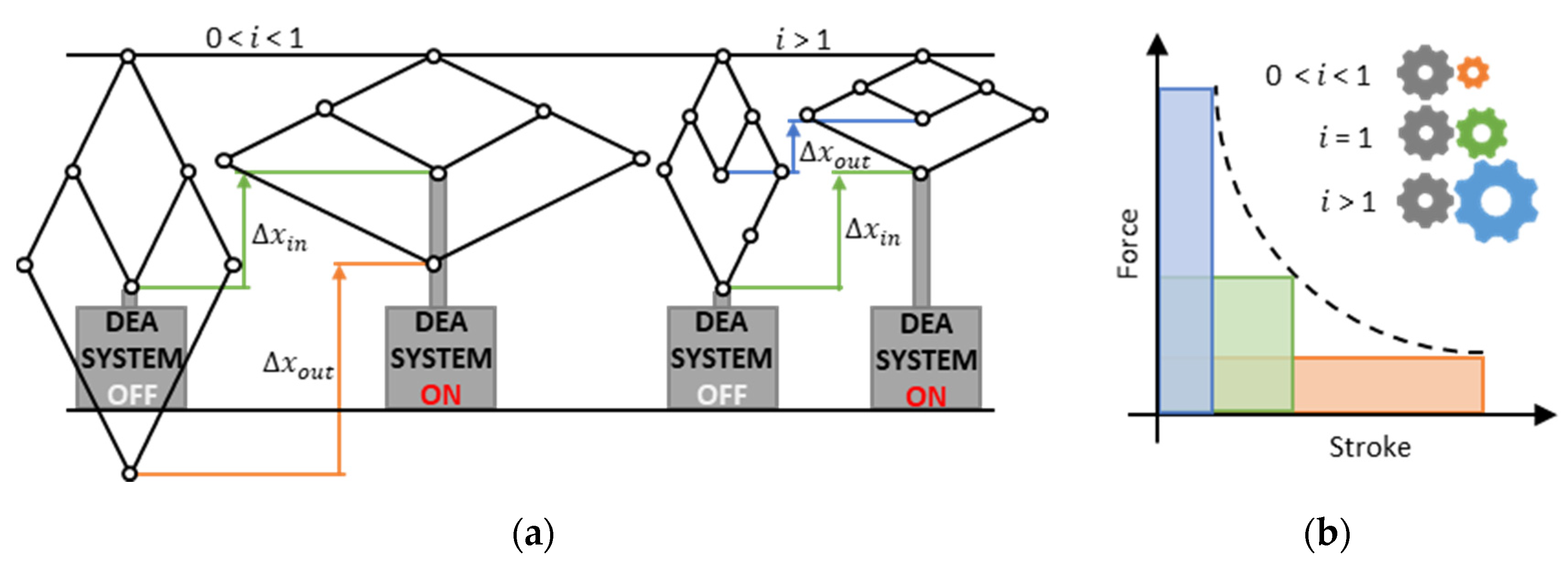
The basic concept under investigation is schematically illustrated in Figure 2a. Depending on its configuration, connecting a scissor linkage mechanism to a DEA system (here shown as a black box) can result either in lower strokes for transmission ratios i > 1 (stroke-reducing) or higher strokes for 0 < i < 1 (stroke-magnifying). The force behaves exactly the opposite way, which is illustrated in a qualitative force-stroke graph in Figure 2b. The figure shows that the system output can be adjusted to either higher forces for i > 1 or to higher strokes for 0 < i < 1, while the colored area of mechanical work (converted within the working range) remains the same if transmission losses are neglected. The DEA system of this work is designed to be efficient and performance-optimized for static operation. This Section uses a generic example to explain the fundamental basics of designing such a system based on SIPs. In addition, kinematics and operating principle of the scissor linkage are explained and general design variants are presented.

2.1. Performance-Optimized DEA Systems for Static Operation

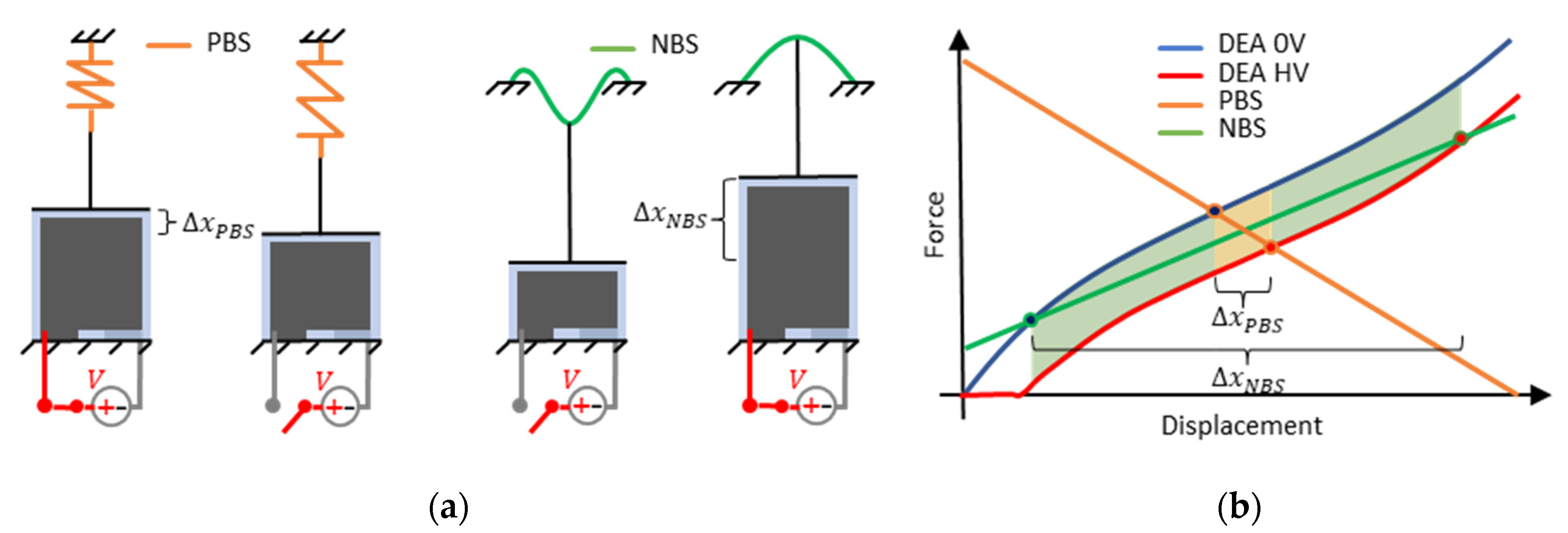
Diaphragm DEAs are not capable of generating compressive forces and must therefore be preloaded with a biasing force. This force can be realized by using different biasing elements such as antagonistic working DEAs [26], masses [22], magnets [31], air pressure [32], or different kinds of spring elements and mechanisms. The choice of the preload characteristics has a decisive influence on the performance of the resulting DEA system, especially for static operation. This is proven in several works [22,23,24,30] and further explained in the following by the schematic illustration in Figure 3, which compares two DEA systems based on identical SIPs. The left-hand side in Figure 3a shows a SIP that is biased with a common tensile spring that behaves as PBS. The output stroke of this system is Δ x P B S in the presence of a high voltage V . The right-hand side of Figure 3a shows an identical SIP, which is biased with an inclined and centrally loaded buckled beam. The force-displacement characteristics of this buckled beam typically are strongly non-linear and have a negative stiffness over a wide range, thus behaving as an NBS. The output stroke of this system is Δ x N B S when a high voltage V is applied. Comparing the two systems one can see that the SIP-NBS system generates a significantly higher stroke. This can also be observed in Figure 3b, where the static design curves of the SIP are drawn in a force-displacement diagram. The SIP curves refer to two different scenarios, respectively with no voltage and a target high voltage applied. The system resulting stroke is identified by the intersections of the DEA curves with the force-displacement curves of the biasing mechanisms. Here, the behavior of the NBS is also assumed to be linear in the considered range for simplicity. Since the biasing mechanisms work against the DEA, their slopes are reversed in the graph. In addition to the stroke, also the mechanical work of the SIP-NBS system (obtained by applying a target voltage on the unloaded DEA), which is indicated by the green and the yellow-colored area in the graph, is significantly higher compared to the SIP-PBS system (yellow area). Hence, the SIP-NBS system not only generates higher stroke but also higher convertible energy which can be further optimized by choosing an appropriate negative stiffness or even a nonlinear characteristic for the bias. Such a system is referred to below as a performance-optimized SIP system or, more generally, a performance-optimized DEA system. The above considerations only apply to the static operation since dynamic effects are not taken into account.
An important observation is that the bias of a DEA system does not represent a classic gear transmission function. Reducing the stroke via the bias stiffness does not automatically increase the force of the actuator by the reciprocal of the stroke reduction factor. Instead, the force remains almost constant, leading to reduced convertible energy. Conversely one can say that the performance optimization of a DEA system with help of the negative stiffness bias goes hand in hand with stroke maximization. A performance-optimized DEA system thus shows a fixed force-displacement response at a given voltage. To alter this characteristic towards higher force or higher stroke with negligible performance losses in terms of convertible energy, an external transmission mechanism is required. This is realized in this work with the help of a scissor linkage mechanism.

2.2. Scissor Linkage as Linear Transmission Mechanism

There exist a wide range of mechanical transmission systems for different applications. The selection of the most suitable transmission mechanism depends on the SIP requirements in terms of stroke/force and on economic considerations. The latter lead, e.g., to the exclusion of pneumatic and hydraulic solutions, which are bulky and require external ancillary systems, and are thus not well suited for small and compact actuator systems such as DEAs, which typically work over comparably lower force ranges. Furthermore, because DEAs typically feature a linear motion, rotatory gear mechanisms do not appear a viable solution to magnify the force or stroke, as they would require additional mechanisms to convert the rotation into a linear movement and vice versa, leading to performance losses, increased system complexity and costs. For this reason, direct linear transmission mechanisms, which can be realized with mechanical linkages, remain the only viable option. A well-known mechanical linkage is the scissor linkage, also called a pantograph, which is used in scissor lifts for example, as a linear transmission. It is based on the planar four-bar mechanism, the geometry and kinematics of which are described in detail in many standard works on mechanics and robotics [33,34]. This mechanism allows up-and-down- scaling of linear movements by means of a lever-like joint arrangement. A variant derived from this mechanism is shown in Figure 4a (the picture shows one half of the complete mechanism, which can be obtained by mirroring the solution shown in the figure with respect to the horizontal axis). The input and output sided joints are guided in the direction of the linear axis of motion, while the central transmission joint is fixed. The entire design (including the hidden half) consists of 6 idealized links connected by 7 joints and, because of its symmetry, only requires one linear guide. The transmission factor i results from geometric and kinematic consideration and reads as:
i = l 2 l 1
with i equaling the ratio of the output and the input linear displacements (in the module)
Δ x o u t = i Δ x i n
or the ratio of the input-to-output force (in the module):
F o u t = 1 i F i n
Notice that, in the mechanism of Figure 4b, both output force and stroke are reversed compared to the input force and stroke. Figure 4b shows that the output side can also be mirrored with respect to the vertical axis. As a result, the direction of movement and force is reverted (i.e., input and output force/displacements are in the same direction). This latter arrangement results in building space optimization for practical system constructions.
The considerations above relate to a system with ideal links and joints. To achieve the described behavior, the links must be realized as rigid bars in order to avoid stretching, compression, and bending. The joints can be realized with pivot bearings or compliant joints.

3. System Construction and Manufacturing

In this Section, the construction of the individual system components such as SIP, inclined and centrally loaded buckled beam, and scissor linkage, as well as the overall assembly are presented and details about materials and manufacturing are given. Results of the experiments and simulations required to identify the relevant construction parameters are explained in Section 4.

3.1. Multi-Layer SIP

A single SIP layer is built, based on a Elastosil 2030 silicone film by Wacker Chemie AG (Munich, Germany) of a thickness of 50 µm, which is screen printed on both sides with a 5 µm electrode made of a conductive mixture of carbon black particles and silicone. The two-axis symmetric print layout is schematically shown in Figure 5a. This layout is designed to enable electrical contact with the SIP electrodes on two opposing sides in the stretching direction, with each side featuring three electrical contacts: a central contact for high voltage application, and two side contacts for applying ground potential. This reduces electrical loading and unloading path lengths and thus enables a faster electro-mechanical response to a given voltage signal. The overall rectangular DEA surface dimension is 66 × 56 mm2, with an active area of 60 × 40 mm2, neglecting passive safety distances between the electrodes and the frames and electrical contacting areas.
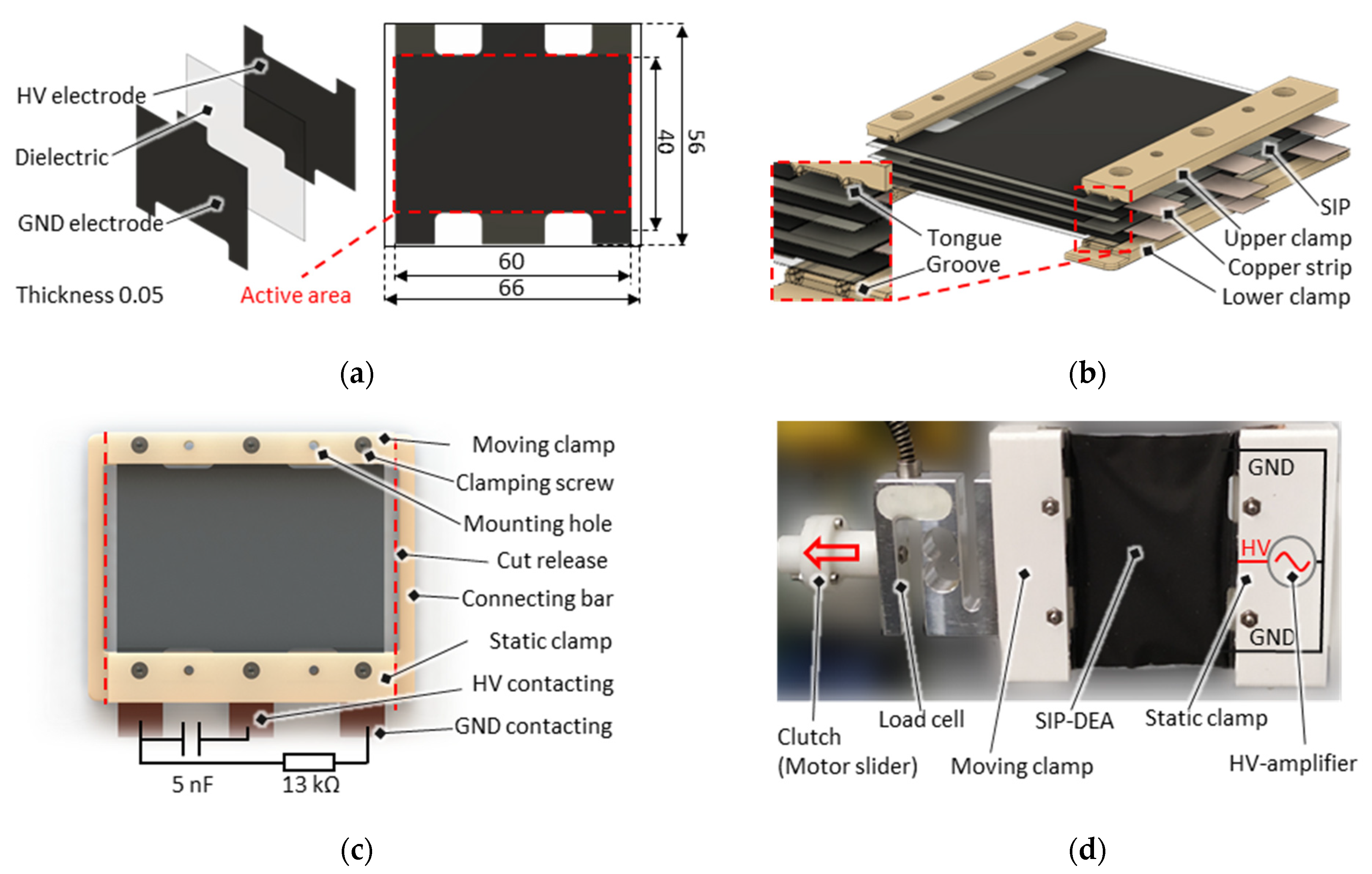
Figure 5b shows an exploded view of the computer-aided design (CAD) of a multi-layer design consisting of four single SIP layers, which are alternately stacked with thin copper strips on the electrical contacting side. The resulting stack is screw-clamped in between two rigid clamping bars on the respective opposite mechanical input and output sides. The clamps are made of an electrical insulating resin-based material via a stereolithographic 3D-printing process with 25 µm resolution. This enables a thin design with fine and burr-free tongue and groove structures close to the outer edges. These structures provide a strain-relief function in order to prevent the film from slipping out of the clamping area. Besides this, they also improve the electrical transition contact by pressing the copper strips firmly onto the carbon electrode surface. In Figure 5c the CAD top view of the total 4-layer SIP assembly is shown. The opposite clamping bars are connected via thin connecting bars in order to maintain the shape and pre-stretching during the system assembly process. In the mounting configuration, the actuator features a capacitance of 5 nF and equivalent series resistance of 13 kΩ. Both quantities are measured with an HM8118 LCR meter (Rohde & Schwarz) with a sinusoidal excitation frequency of 1 kHz and excitation amplitude of 1 V. After the SIP has been assembled, the mechanical connecting bars are simply cut free. Depending on the mechanical biasing mechanism, this release of the SIP leads to modification in the equilibrium configuration and thus a change in the electrical properties. As an example, a photo of a released 4-layer SIP is shown in Figure 5b. In this case, the SIP is installed on a tensile test bench, which enables recording continuous force-displacement curves with an applied high voltage. More details about the corresponding electromechanical characterization experiments are given in Section 4.

3.2. Inclined and Centrally Loaded Buckled Beam NBS

As discussed in Section 2, a statically operated performance-optimized DEA system requires a negative-slope mechanical bias. In this work, such a bias is represented by an inclined and centrally loaded buckled beam, which is shown as a 3D-CAD design in Figure 6a. This is manufactured by laser-cutting a spring steel sheet (CrNi 1.4310) of high precision thickness into a defined rectangular shape and providing it with three rigid stereolithographic 3D-printed clamps, one on either edge and one in the middle. The clamping force is applied via screws, guided with narrow drilling holes through the beam. The side clamps feature dove-tail guiding to be able to compensate for manufacturing and assembly tolerances before fixing the mechanism onto a rigid housing. The middle clamp is provided with a mounting flange for the moving side of the multi-layer SIP, which can be screwed in place via two matching holes.
In its original configuration, the undeformed beam illustrated in the lower part of Figure 6b is flat and free from mechanical stresses. The beam reaches its final buckled shape in three steps. First, the outer clamps are pushed towards each other horizontally. This causes the beam parts and the middle clamp to buckle upwards. In a second step, the outer clamps are then inclined to a defined angle and fixed in their final configuration. In this configuration, the beam shows a single buckled shape (U-shape). The beam is then centrally loaded in a third step by moving the middle clamp from the top down. In this range, the beam exhibits a non-linear force-displacement response, which rises to a local maximum first, then decreases with a negative slope, and subsequently rises again. In loaded configuration (i.e., when the beam is coupled with the SIP), the shape of the beam changes into a double-buckled shape (W-shape) as soon as the slope of the reaction force becomes negative. The force-displacement characteristics and the determination of the final parameters given in Figure 6b are explained in more detail in Section 4.

3.3. Non-Inversing Scissor Linkage Transmission Mechanism

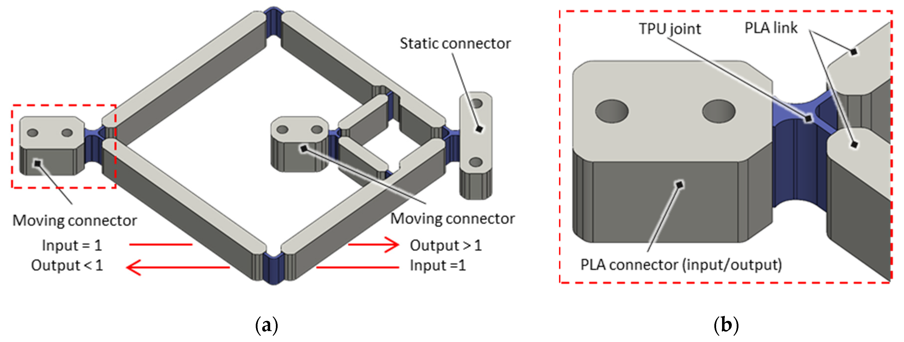
The scissor linkages, the working principle of which has already been explained in Section 2, are designed with compliant joints and realized as a one-piece solution. It is manufactured with an Ultimaker UM3 filament printer with a dual head function. This way, two different filament materials are woven together in layers, a soft and flexible thermoplastic polyurethane (TPU) material for the joints and a rigid polylactide (PLA) material for the links. The 3D-CAD design of the mechanism is shown in Figure 7a, with a more detailed view given in Figure 7b. The chosen non-inversing transmission variant adapts to the structure of the multi-layer SIP, which is flat and of an approximately square shape. The length of the links is selected in such a way, that a transmission ratio of i = 3:1 is achieved for stroke reduction or i = 1:3 for stroke magnification the stroke if input and output sides are swapped. The mechanisms are printed to be free of mechanical stresses in the middle of their working range. The design of the compliant joints is optimized through an iterative experimental procedure. The relevant design parameters here are the joint thickness and radius (or length). On the one hand, the thickness of the joints must be large enough to transmit the incoming and outgoing forces. On the other hand, it must be as thin as possible to minimize the torsional stiffness associated with the loads and the hysteretic behavior caused by the TPU material. The radius of the joints must be small enough to mimic an ideal point rotary joint, but large enough to prevent the joint from being too stiff and the hysteretic losses from being too high.

3.4. SIP Actuator System

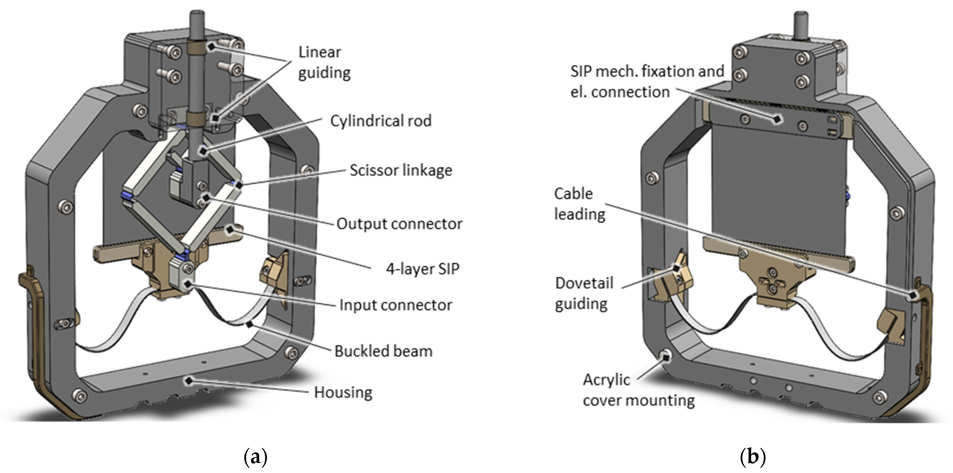
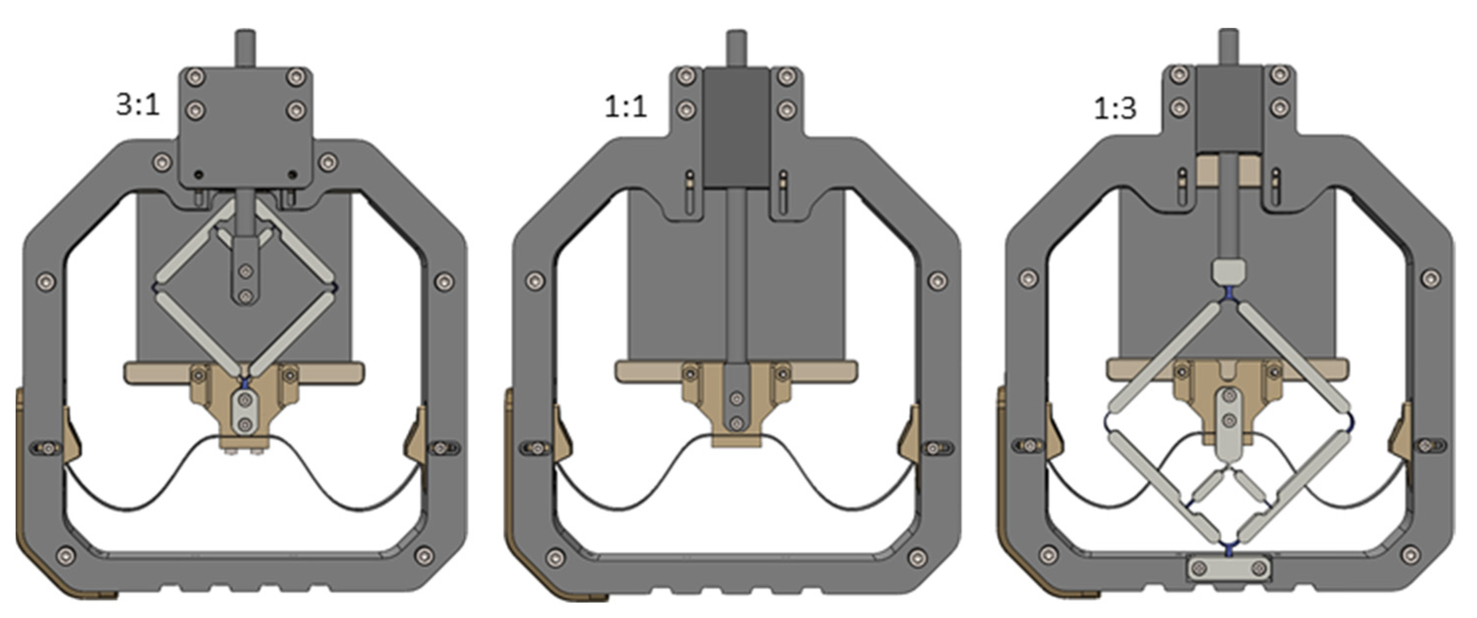
The components presented above are combined into housing to form a SIP actuator system. Figure 8 illustrates the CAD assembly of one version with stroke-reducing characteristics ( i = 3:1) as an example, with Figure 8a showing the transmission mechanism side and Figure 8b showing the SIP side. The housing, which is of nearly square dimension, is also 3D-printed and consists of a rigid polyethylene terephthalate (PET) filament. On the lower side, it accommodates the inclined buckled beam NBS via female dove-tail guides and enables them to be fixed after a horizontal linear adjustment. The moving side of the SIP is mounted via the SIP-NBS flange, featured by the middle clamp of the NBS. The opposing static side of the SIP is fixed by screws to the upper edge of the housing and can be adjusted vertically beforehand with help of slotted holes. This enables to obtain a defined mechanical preload of the SIP-NBS system and an exact adjustment of the mechanical working point. For the stroke-reducing transmission, the static connector of the scissor linkage is also attached to the upper edge of the housing, and the outer moving connector, representing the input side, is attached to the SIP-NBS flange. The inner moving connector, representing the output side of the transmission, carries along a cylindrical rod which is led through a linear guiding outside of the housing. The movement of this rod can be used to drive an external load by applying a voltage to the electrical contacts, which are led out of the side of the housing. Both sides of the housing are covered with a transparent acrylic glass pane so that the housing is closed, and the user does not come into contact with electrical or mechanical system components for safety reasons. Thanks to this measure, the system is also protected from environmental factors such as moisture and dust. A frontal view of the transmission side of the actuator is shown in Figure 9. Besides this stroke-reducing system ( i = 3:1), another system without a transmission mechanism ( i = 1:1) and one with stroke-magnifying transmission ( i = 1:3), is designed and manufactured.
For the system without a transmission mechanism, the SIP is directly transmitted to the cylindrical rod. In the stroke-magnifying system, conversely to the stroke-reducing transmission system, the input side is represented by the inner movable mechanical connector and the output by the outer movable connector. Because it aims to achieve large strokes, the stroke-magnifying implementation is also of bigger dimension due to the limited manufacturing resolution of the 3D printer, which requires a certain minimum size for the links and the joints.

4. System Characterization

This section covers the technical system design process and the characterization of the resulting SIP actuator systems. For this purpose, the design process is explained, experimental setups are described, and measurement results are provided.

4.1. Multi-Layer SIP

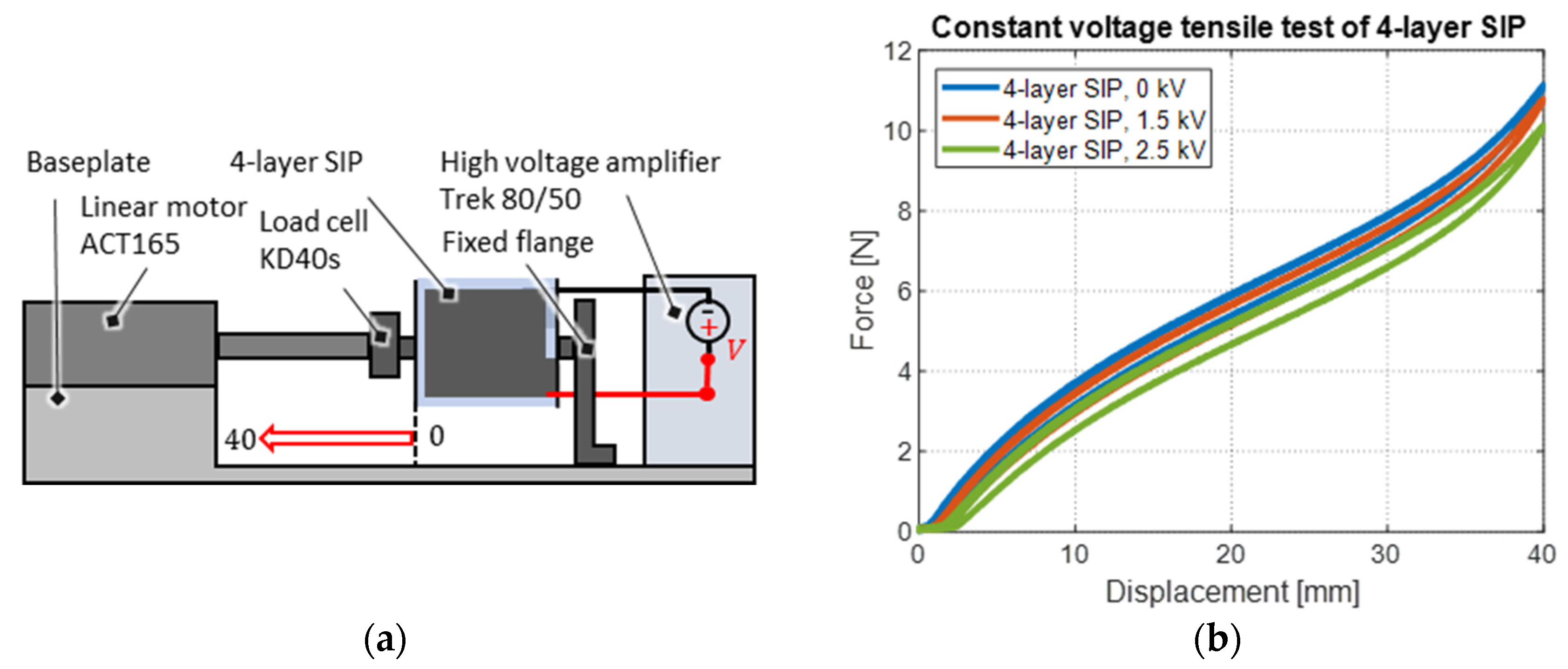
The first step in the static design process of the SIP actuator system is the characterization of the force-displacement behavior of the presented multi-layer SIP at different applied voltages. For this purpose, tensile tests are carried out on a test bench that is schematically illustrated in Figure 10a, and which is partially shown in the photo in Figure 5d. The static clamp of the SIP is mechanically fixed to an aluminum flange and electrically connected to a Trek Model 5/80 high-voltage amplifier, which provides voltages of up to 5 kV and currents up to 80 µA. The movable clamp of the SIP is connected to an Aerotech ACT165 linear motor, which provides strokes of up to 165 mm. In between linear motor and SIP, a load cell type KD40s by ME-Meßsysteme GmbH (Henningsdorf, Germany) is mounted, which provides a force measurement range of up to 10 N. Control and data acquisition are implemented in a real-time high-resolution National Instruments LabVIEW FPGA environment. The starting position of each experiment is chosen in such a way that the SIP exerts no tensile force on the load cell when no electrical voltage is applied. From this position, the motor executes a sinusoidal motion with a stroke of 40 mm and a frequency of 0.1 Hz, with a constant prescribed voltage.
Figure 10b shows the resulting force-displacement curves of three tensile tests, which are performed with different voltage levels. The SIP response exhibits a characteristic nonlinear hysteretic shape. Due to quadratic relations between voltage and electrostatic force, the voltage-induced force reduction between the 0 kV curve and the 1.5 kV curve is relatively small in comparison to that between 1.5 kV and 2.5 kV. This means that a higher actuator performance can be achieved in a higher voltage range. However, the voltage is limited due to a maximum allowed electric field through the dielectric film until an electrical breakdown occurs. With 40 mm of stretch (100% strain), the electric field already reaches about 100 V/μm at 2.5 kV, which is already above the nominal breakdown field of 80 V/μm of the Wacker Elastosil 2030 film. The voltage should therefore not be further increased unless the maximum working stretch is reduced.

4.2. Inclined and Centrally Loaded Buckled Beam NBS

The approximately linear force-displacement response of the SIP in between 10 mm and 30 mm of stretch is advantageous for the design of the NBS mechanism in the second step of the design process. A suitably designed NBS can provide the system with a stroke of 20 mm, which can potentially be achieved with a maximum SIP elongation of 30 mm (75% stretch) and thus allows the maximum applicable voltage to rise to 2.9 kV with a target electric field of 100 V/μm. The corresponding force-displacement curves for the SIP system design are shown in Figure 11a, where the average curves originated from the originally hysteretic-shaped curves are considered.
The vertical distance between the two design curves for the SIP (at 0 and 2.9 kV) shows that in the desired working range, a force increase of approximately 1 N can be achieved. The (reverted) negative slope range of the force-displacement curve of the NBS is now selected in a way that it intersects the 0 V curve once below 10 mm elongation and the 2.9 kV curve once above 30 mm elongation, to repeatably achieve a target stroke of at least 20 mm. As already mentioned in Section 3, this characteristic can be manipulated for an inclined and centrally loaded buckled beam NBS leveraging on a number of construction parameters such as Young’s modulus of the material, length, width, and thickness of the undeformed beam, inclination angle, and axial compression factor. A parametric study using a two-dimensional FE-model implemented in the Solid Mechanics Module of COMSOL Multiphysics 5.6 is performed, the result of which yields a suitable configuration of the beam construction parameters for the desired force-displacement behavior. The construction parameters identified in this study are given in Figure 6b. The corresponding force-displacement characteristic obtained in simulation is plotted in the diagram in Figure 11b. The NBS response shows a force increase up to a value of 7 N, which is reached in correspondence with a stroke of 14 mm. Increasing the stroke, the force decreases over a travel range of 38 mm to a force of 1 N and thus shows a negative slope, before it increases again. The FE-model considers geometric nonlinearities as well as large deformations and can also be used to determine the mechanical stresses present in the beam. In this way, plastic deformation can be avoided, and fatigue strength is ensured by selecting a suitable beam thickness to guarantee a certain margin with respect to the yield stress. Figure 11c shows the mechanical 2nd Piola–Kirchhoff stresses (i.e., the nominal stress in the beam tangent direction), derived from the simulation, in the right (symmetrical) half of the beam. In the picture, the beam thickness is scaled up by a factor of 10 to make the mechanical stress distribution visible in better detail. Maximum stresses occur in the regions with the highest bending at the beam surface, e.g., in correspondence of the connection with the middle clamp. The maximum stress is below the maximum tolerated value of 2.2 GPa for the spring steel used, which makes the beam sufficiently thin. A direct comparison between the force-displacement curves of the simulation result and the corresponding experiment, also given in Figure 11b, shows good agreement between model and measurements and confirms the model validity. The tensile test setup used for the corresponding experiment is schematically illustrated in Figure 11d. It consists of an Aerotech Ant-25L linear stage, which is mounted on an aluminum baseplate. A 10 N KD40s Loadcell by ME-Meßsysteme GmbH (Henningsdorf, Germany) is mounted on the slider of the motor. The inclined buckled beam is mounted on an aluminum flange, which is also fixed to the base plate in front of the motor and connected to the other side of the load cell via the middle clamp. This way, the motor loads the buckled beam centrally, pushing it from left to right. The motor stroke is measured with an integrated encoder. The test starts at a deflection of ~15 mm, where the beam in principle already features a negative force gradient and starts to buckle towards a stable W-shape. This initial configuration is chosen because the transition from the U-shape- to the W-shape is unsteady and often leads to hysteresis due to insufficient linear guiding. The test is stopped after only ~30 mm of travel since the large bending would otherwise lead to mechanical stresses that would plastically deform the beam. Thus, the measurement does not cover the entire displacement range of the simulation, but it confirms that the beam features the desired simulated response over the negative slope range exploited by the system. Because the bias mechanism works against the DEA, for the plot in Figure 11a a coordinate transformation is performed that results in the displacement coordinate of the NBS being inverted. With this choice, the intersection points between the SIP response curves and the NBS curve represent equilibrium points for the coupled system at different applied voltages. A force offset of 0.65 N is added, shifting up the curves vertically. The additional force offset results from the moving weight of the attached parts of the actuator system. The curves are then shifted horizontally by 13 mm to the right, resulting in optimal working points for the actuator stroke. In the construction, this coordinate shift is realized by the slotted holes which enable to adjustment the strain of the SIP, which is working against the NBS. The intersections of the design curves thus show that the actuator system can theoretically produce 25 mm of stroke in free conditions (in the absence of external loads) based on the measured NBS curve, which is 2 mm less than the stroke predicted from the theoretical NBS curves. It is also evident from the design curves that the actuator system has a nearly bistable characteristic over most of its operating range since the bias system curves exhibit a slope that is very close to (or even steeper than) the SIP curves. This causes the actuator to rapidly jump from the lower position to the higher one, as soon as a certain voltage threshold is exceeded, and the mechanical working point enters this range. Conversely, the actuator jumps from the upper position to the lower one when the electrical voltage falls below a certain value.

4.3. Non-Inversing Scissor Linkage Transmission Mechanism

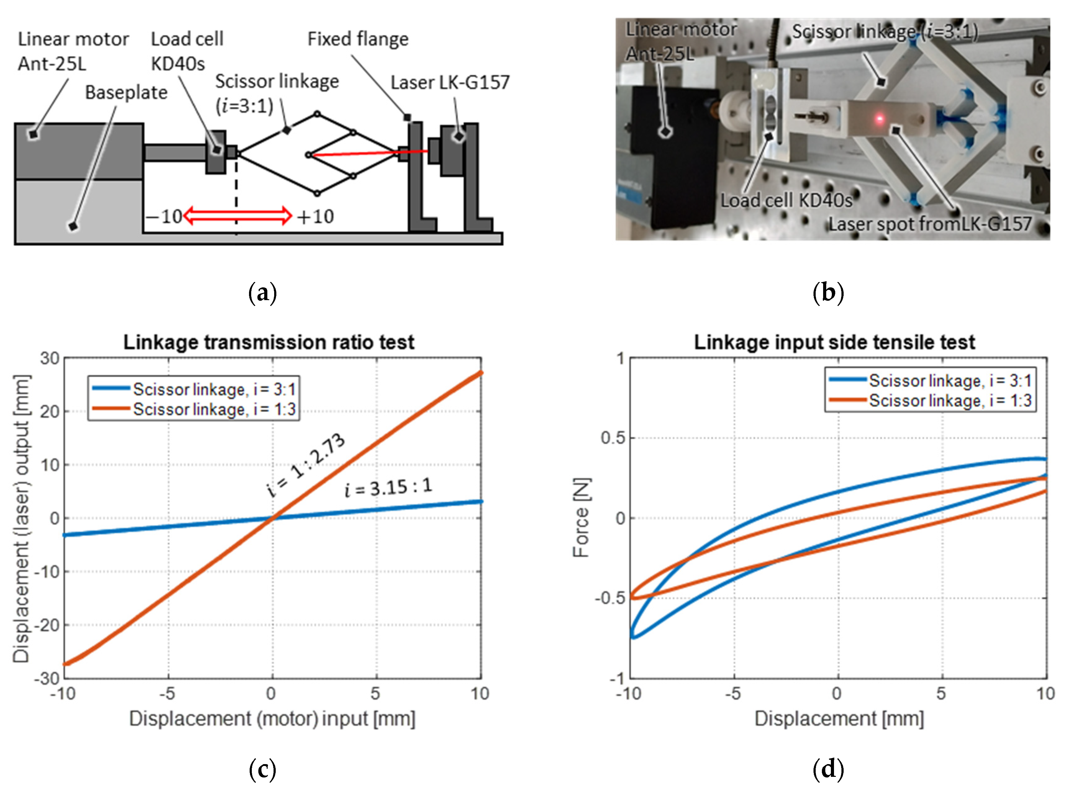
Since the actuator system can theoretically generate approximately 1 N of force over the entire travel range, the applied load shall not exceed this force. Due to non-ideal linear transmission behavior and joint friction, the flanged scissor linkage mechanisms also represent a load, which must be minimized in a third step of the design process, while maintaining the desired transmission factor. As already explained in Section 3, this is done in an iterative experimental way, setting the attention on the joints. The load of the final mechanisms is characterized with the help of a tensile test performed on the transmission input side. This is carried out with the same test rig as used for the NBS, but with a modified flange for the fixed connection of the scissor linkage. In addition, the stroke output is measured with a Keyence LK-G157 laser sensor to validate the transmission factor. The experiment for the stroke-reducing mechanism ( i = 3:1) is schematically shown as a representative example in Figure 12a, with a corresponding photo in Figure 12b. Since the SIP-NBS system is expected to achieve a target-stroke of 20 mm, the transmission mechanism must cover this range. Thus, the tensile test is performed with a bidirectional 10 mm deflection around the initial configuration of the mechanisms, where the material stress of the joints is approximately zero. The prescribed displacement consists of a sinusoidal trajectory with a frequency 0.1 Hz, starting from the +10 mm position. The laser position measurement for both systems is plotted over the motor stroke in the diagram in Figure 12c. The plot shows an approximately linear stroke transmission for both systems. The measured stroke-reducing transmission ratio results in i = 3.15:1, which exceeds the target value by 5%. The stroke-magnifying transmission ratio results in i = 1:2.73 which falls below the target value by 10%.
The real measured stroke-reducing and stroke-magnifying ratios differ from the target values for two reasons. First, due to manufacturing tolerances, minor dimensional deviations occur in the lengths of the links and thus in the leverage ratios, which are highly sensitive to the links dimensions. Secondly, a larger deviation results from the fact that instead of ideal pin couplings, compliant joints are used, whose geometry and dimensions systematically influence the leverage ratios. Despite these deviations, the transmission ratios are still satisfactorily close to the target values.

4.4. SIP Actuator System

Each of the three realized systems is characterized in terms of the stroke achieved upon electrical excitation. The experimental setup used for this purpose is illustrated schematically in Figure 13a and shown as a photo in Figure 13b. The setup includes a C-shaped aluminum frame, where the SIP actuator system is fixed on the bottom baseplate, and the laser type LK-G157 of by Keyence Corporation (Osaka, Japan) is mounted above. The laser beam aims at the surface of the guided cylindrical rod, where the stroke output of the SIP system is measured. The SIP is electrically connected to a high-voltage amplifier HA51U-3P5 by hivolt.de GmbH & Co. KG (Hamburg, Germany). Control and data acquisition are implemented in a real-time high-resolution National Instruments LabVIEW FPGA environment. Each of the systems is supplied with a voltage step of amplitude 2.9 kV. As explained in Section 4.2., the system is designed to be bistable and no proportional positioning can be achieved. Applying a steep voltage excitation helps overcome static friction effects by exploiting the system’s dynamic response. The resulting voltage excitation and corresponding stroke response of the SIP actuator system with no transmission mechanism ( i = 1:1) are given in Figure 13c. The response of the system stroke to the voltage excitation is highly dynamic. It initially presents a set of underdamped free oscillations, then settles with a transient behavior to a maximum value of 20 mm within 0.5 s, and then remains constant. Also, if the voltage is switched off, the system reacts very quickly and exhibits an underdamped dynamic behavior before settling back to the initial position.
Figure 13d shows the stroke-measurement of each system in the same diagram for a direct comparison. The stroke-reducing system ( i = 3:1) also reacts with a short overshoot which settles immediately to a constant stroke of 6.3 mm. The stroke-magnifying system ( i = 1:3) also initially responds comparatively quickly to the voltage excitation until a stroke of 20 mm is reached. Then the stroke increases only slowly, although the maximum voltage has already been reached. The actuator thus creeps to a maximum stroke of 53 mm within 5 s. When the voltage is switched off, it behaves in a similar way, but reverse order. However, it no longer reaches the starting position within 5 s, but only returns up to a deflection of approximately 2 mm.

5. Discussion

The system designs of the presented systems generate strokes consistent with the expected values. These expected values are compared with the measurement results in the following and possible reasons for their deviations are explained. In addition, perspectives are given for improvement measures that could lead to a reduction of the deviations.
Regarding stroke, 25 mm is expected for the system without a transmission mechanism ( i = 1:1), with regards to the design curves in Figure 11a. However, the measurement results shown in the diagrams of Figure 13c,d indicate a lower stroke of only 20 mm. The difference owes to the fact that the generated forces are small, especially at the left and right edges of the designed working range, therefore even small disturbances can cause the SIP actuator to stop there. In addition, friction and tensioning effects occur in the assembly, which are not detectable from the measurement of the individual system components, such as friction on the linear guided cylindrical rod. The SIP actuator system can thus not be considered to be completely load-free, and the achievement of a smaller stroke compared to the theoretical value is expected. Taking a stroke of 20 mm for the reference (unreduced) SIP, the stroke of the stroke-reducing system results in a targeted value of 6.7 mm ( i = 3:1) or an expected value of 6.35mm ( i = 3.15:1), based on the measurement of the scissor linkage transmission ratio in Section 4. According to the stroke measurement presented in Figure 13d, 6.22 mm is achieved for the stroke-reducing system which is 98% of the expected stroke. For the stroke-magnifying system, the targeted stroke is 60 mm ( i = 1:3), with an expected value of 54.60 mm ( i = 1:2.73), regarding the measurement results of the real transmission ratio. According to the measurements presented in Figure 13d, 53.00 mm are achieved for the stroke-magnifying system which is 97% of the expected stroke. Similar explanations can be found for these deviations as for the pure SIP-NBS system. The mechanical stresses and frictional forces caused by the assembly of the overall system, which limit the actuator stroke, are even higher in these systems due to the additional transmission component. In addition, the load curves of the scissor linkage mechanisms shown in Figure 12d only fit very narrowly into the working space of the SIP-NBS system. This applies in particular to the stroke-magnifying mechanism ( i = 1:3) showing non-linear behavior in the lower stroke range, which can be a reason for the observed creep behavior. However, these results show that the functional principle of the transmission mechanisms is very close to the design predictions, and the stroke characteristics of the actuator can be scaled as desired with very little error.
Regarding force, the design curves in Figure 11a show that a SIP-NBS system without a transmission mechanism ( i = 1:1) can generate approximately 1 N of force on the drive input side over a stroke range of 20 mm regarding the distance between the 0 kV curve and 2.9 kV curve. Of this, an average of 0.5 N can be used for the upward movement and 0.5 N for the downward movement. However, this force is not distributed homogeneously over the entire stroke range, because the mechanical biasing curve is not exactly located halfway in between the two curves with and without voltage. This holds especially true for the outer edges of the working area. For this reason, a steep excitation signal is chosen to avoid stiction effects, which would cause the actuator to stop prematurely. Force measurements over the travel range can only be carried out configuration-wise as blocking force measurements. This requires the entire system to be clamped in one fixed position (or several fixed positions) so that no stroke can be generated when voltage is applied. Blocking constraints introduce transversal force components in the system, which alter the SIP response and, because of the low forces involved, make the overall force measurement unreliable. In order to achieve reliable force measurement results as well as stroke measurement results, which are closer to the expected values, the systems might be re-designed at a larger force scale on the one hand. On the other hand, the internal system loads could be further reduced. In this regard, the NBS bias mechanism could be designed by also taking into account the stiffness introduced by the scissor linkage mechanisms (and not only the SIP). In addition, system friction could be reduced especially via further optimization of the compliant joints, e.g., by varying the geometry and materials.

6. Conclusions and Outlook

This work presents a diaphragm dielectric elastomer actuator (DEA) system based on a multi-layer stack of strip-in-plane (SIP) DEAs, which is mechanically preloaded with an inclined and centrally loaded buckled beam that is used as a negative biasing spring (NBS). The combination of these two systems allows for designing an actuator system with optimized force-displacement characteristics, which results in a comparatively high-performance output in terms of cyclic energy density for static operation. Three identical DEA systems are realized, with two of them coupled with scissor linkage mechanisms, one providing transmission ratio i = 1:3 and one ratio i = 3:1. The mechanisms are designed in such a way, that they adapt to the flat and rectangular shape of the SIP-NBS system and can be implemented as a one-piece solution with low manufacturing and assembly cost. In the paper, the working principle and design rationale of the single parts, as well as the overall system design, are discussed, and the resulting up-/down-scaled SIP actuator systems are characterized in terms of their stroke behavior and compared with the third reference system, which is not coupled to any transmission mechanism ( i = 1:1). The results show that the functional principle of the transmission mechanisms provides a system response close to theoretical predictions, and the stroke characteristics of the actuator can be adjusted as desired with a tolerable error. To achieve reliable force measurements, the systems should be redesigned at a larger force scale. However, this work shows that it is possible to up-/downscale stroke and force of diaphragm DEA systems via compliant mechanisms and adapt the actuator system characteristics to different loads. The mechanism is therefore suitable for lean and performance-optimized DEA designs, which rely on a standard design and set of dimensions for the DEA unit and serve different loads or applications through suitably designed transmission mechanisms.
For future development, the scissor linkage mechanisms can be further optimized in terms of the compliant joint friction, which can be reduced e.g., by optimizing the geometry and materials. Joint and linkage optimization could also be carried out with regard to the forces to be transmitted in order to further improve transmission characteristics and lean design. The Blocking force measurements on the system could be obtained with an appropriately designed setup and/or a continuum mechanical model, e.g., a Finite Elements (FE) model. Furthermore, the contribution of the positive slope force-displacement characteristics of the scissor linkage mechanism could be explicitly accounted for in the design flow and compensated by a suitably designed NBS. One step further, the NBS properties can also be integrated into the scissor linkage mechanism using positive linear springs, as it is proposed for the four-bar mechanism [27,28,29]. This would allow the design and manufacturing to be further simplified, e.g., by resorting to fully-3D printed elastic biasing elements.

Author Contributions

Conceptualization, D.B., T.P.W. and H.C.S.; Data curation, D.B. and H.C.S.; Formal analysis, D.B. and H.C.S.; Funding acquisition, P.M.; Investigation, D.B. and H.C.S.; Methodology, D.B. and T.P.W.; Project administration, D.B.; Resources, D.B. and T.P.W.; Supervision, D.B. and P.M.; Validation, D.B. and H.C.S.; Visualization, D.B. and H.C.S.; Writing–original draft, D.B.; Writing–review & editing, T.P.W. and P.M. All authors have read and agreed to the published version of the manuscript.

Funding

This research received no external funding.

Data Availability Statement

The data that support the findings of this study are available from the corresponding author upon reasonable request.

Conflicts of Interest

The authors declare no conflict of interest.

References

  1. Pelrine, R.E.; Kornbluh, R.D.; Joseph, J.P. Electrostriction of polymer dielectrics with compliant electrodes as a means of actuation. Sens. Actuators A Phys. 1998, 64, 77–85. [Google Scholar] [CrossRef]
  2. Pelrine, R.; Kornbluh, R.; Joseph, J.; Heydt, R.; Pei, Q.; Chiba, S. High-field deformation of elastomeric dielectrics for actuators. Mater. Sci. Eng. C 2000, 11, 89–100. [Google Scholar] [CrossRef]
  3. Carpi, F.; De Rossi, D.; Kornbluh, R.D.; Pelrine, R.; Sommer-Larson, P. Dielectric Elastomers as Electromechanical Transducers, 1st ed.; Elsevier: Amsterdam, The Netherlands, 2008. [Google Scholar]
  4. Chen, Y.; Agostini, L.; Moretti, G.; Fontana, M.; Vertechy, R. Dielectric elastomer materials for large-strain actuation and energy harvesting: A comparison between styrenic rubber, natural rubber and acrylic elastomer. Smart Mater. Struct. 2019, 28, 114001. [Google Scholar] [CrossRef]
  5. Madsen, F.B.; Yu, L.; Daugaard, A.E.; Hvilsted, S.; Skov, A.L. Silicone elastomers with high dielectric permittivity and high dielectric breakdown strength based on dipolar copolymers. Polymer 2014, 55, 6212–6219. [Google Scholar] [CrossRef]
  6. Wissler, M.; Mazza, E. Mechanical behavior of an acrylic elastomer used in dielectric elastomer actuators. Sens. Actuators A Phys. 2007, 134, 494–504. [Google Scholar] [CrossRef]
  7. Rosset, S.; Shea, H.R. Flexible and stretchable electrodes for dielectric elastomer actuators. Appl. Phys. A 2013, 110, 281–307. [Google Scholar] [CrossRef] [Green Version]
  8. Mose, F.; Pourazadi, S.; Wantono, C.; Menon, C. Study on electric properties of graphene and carbon black nanoparticles as compliant electrode for dielectric elastomer actuators. In Proceedings of the International Conference on Smart Materials and Structures (CANSMART), Vancouver, BC, Canada, 15–17 July 2015. [Google Scholar]
  9. Jones, R.W.; Wang, P.; Lassen, B.; Sarban, R. Dielectric elastomers and compliant metal electrode technology. In Proceedings of the Melecon 2010—2010 15th IEEE Mediterranean Electrotechnical Conference, Valletta, Malta, 26–28 April 2010; pp. 368–373. [Google Scholar] [CrossRef]
  10. Fasolt, B.; Hodgins, M.; Rizzello, G.; Seelecke, S. Effect of screen printing parameters on sensor and actuator performance of dielectric elastomer (DE) membranes. Sens. Actuators A Phys. 2017, 265, 10–19. [Google Scholar] [CrossRef]
  11. Araromi, O.; Conn, A.; Ling, C.; Rossiter, J.; Vaidyanathan, R.; Burgess, S. Spray deposited multilayered dielectric elastomer actuators. Sens. Actuators A Phys. 2011, 167, 459–467. [Google Scholar] [CrossRef]
  12. Hubertus, J.; Croce, S.; Neu, J.; Rizzello, G.; Seelecke, S.; Schultes, G. Influence of residual stresses of sputtered thin film electrodes for dielectric elastomer applications. Proceedings 2020, 64, 2. [Google Scholar]
  13. Zhu, Y.; Giffney, T.; Aw, K. A Dielectric elastomer-based multimodal capacitive sensor. Sensors 2022, 22, 622. [Google Scholar] [CrossRef]
  14. Rizzello, G.; Naso, D.; York, A.; Seelecke, S. A self-sensing approach for dielectric elastomer actuators based on online estimation algorithms. IEEE/ASME Trans. Mechatron. 2017, 2, 728–738. [Google Scholar] [CrossRef]
  15. Franke, M.; Ehrenhofer, A.; Lahiri, S.; Henke, E.-F.M.; Wallmersperger, T.; Richter, A. Dielectric elastomer actuator driven soft robotic structures with bioinspired skeletal and muscular reinforcement. Front. Robot. AI 2020, 7, 178. [Google Scholar] [CrossRef] [PubMed]
  16. Hau, S.; Rizzello, G.; Hodgins, M.; York, A.; Seelecke, S. Design and control of a high-speed positioning system based on dielectric elastomer membrane actuators. IEEE/ASME Trans. Mechatron. 2017, 22, 1259–1267. [Google Scholar] [CrossRef]
  17. Giousouf, M.; Kovacs, G. Dielectric elastomer actuators used for pneumatic valve technology. Smart Mater. Struct. 2013, 22, 104010. [Google Scholar] [CrossRef]
  18. Linnebach, P.; Rizzello, G.; Seelecke, S. Design and validation of a dielectric elastomer membrane actuator driven pneumatic pump. Smart Mater. Struct. 2020, 29, 75021. [Google Scholar] [CrossRef]
  19. Hosoya, N.; Masuda, H.; Maeda, S. Balloon dielectric elastomer actuator speaker. Appl. Acoust. 2019, 148, 238–245. [Google Scholar] [CrossRef]
  20. Bednar, S.; Modrak, J. Product variety management as a tool for successful mass customized product structure. Pol. J. Manag. Stud. 2015, 12, 16–25. [Google Scholar]
  21. Dombrowski, U.; Ebentreich, D.; Mielke, T.; Zahn, T.; Richter, T. Einführung lean development. In Lean Development: Aktueller Stand und Zukünftige Entwicklungen; Dombrowski, U., Ed.; Springer: Berlin/Heidelberg, Germany, 2015; pp. 139–196. [Google Scholar] [CrossRef]
  22. Heim, J.R.; Polyakov, I.; Zarrabi, A.; Hui, O. Electroactive Polymer Transducers Biased for Increased Output. U.S. Patent 7915790B2, 29 March 2011. [Google Scholar]
  23. Hodgins, M.; Seelecke, S. Experimental Analysis of Biasing Elements for Dielectric Electro-Active Polymers. Proc. SPIE-Int. Soc. Opt. Eng. 2011, 7976, 797639. [Google Scholar] [CrossRef]
  24. Hau, S.; Bruch, D.; Rizzello, G.; Motzki, P.; Seelecke, S. Silicone based dielectric elastomer strip actuators coupled with nonlinear biasing elements for large actuation strains. Smart Mater. Struct. 2018, 27, 74003. [Google Scholar] [CrossRef]
  25. Berselli, G.; Vertechy, R.; Vassura, G.; Castelli, V.P. Design of a linear dielectric elastomer actuator of conical shape with quasi-constant available thrust. In Proceedings of the 2009 International Conference on Intelligent Engineering Systems, Bridgetown, Barbados, 16–18 April 2009; pp. 89–94. [Google Scholar]
  26. Liu, Y.; Liu, B.; Yin, T.; Xiang, Y.; Zhou, H.; Qu, S. Bistable rotating mechanism based on dielectric elastomer actuator. Smart Mater. Struct. 2019, 29, 15008. [Google Scholar] [CrossRef]
  27. Luo, B.; Li, B.; Yu, Y.; Yu, M.; Ma, J.; Yang, W.; Wang, P.; Jiao, Z. A Jumping robot driven by a dielectric elastomer actuator. Appl. Sci. 2020, 10, 2241. [Google Scholar] [CrossRef] [Green Version]
  28. Plante, J.-S.; Dubowsky, S. On the performance mechanisms of dielectric elastomer actuators. Sens. Actuators A 2007, 137, 96–109. [Google Scholar] [CrossRef]
  29. Chouinard, P.; Plante, J.-S. Bistable antagonistic dielectric elastomer actuators for binary robotics and mechatronics. Mechatron. IEEE/ASME Trans. 2012, 17, 1–9. [Google Scholar] [CrossRef]
  30. Conn, A.; Rossiter, J. Radially expanding mechanism for dielectric elastomers. Proc. SPIE-Int. Soc. Opt. Eng. 2010, 7642, 76420P. [Google Scholar] [CrossRef]
  31. Loew, P.; Rizzello, G.; Seelecke, S. Permanent magnets as biasing mechanism for improving the performance of circular dielectric elastomer out-of-plane actuators. Electroact. Polym. Actuators Devices 2017, 10163, 101630Y. [Google Scholar] [CrossRef]
  32. Bernat, J.; Kołota, J. DEAP Actuator composed of a soft pneumatic spring bias with pressure signal sensing. Energies 2021, 14, 1189. [Google Scholar] [CrossRef]
  33. McCarthy, J.M.; Soh, G.S. Planar kinematics. In Geometric Design of Linkages; Springer: Berlin/Heidelberg, Germany, 2011; pp. 75–92. [Google Scholar] [CrossRef] [Green Version]
  34. Chaudhary, N.; Gupta, A. Multi-body analysis for a four-bar mechanism using RecurDyn and MATLAB. In Machines, Mechanism and Robotics; Springer: Berlin/Heidelberg, Germany, 2022; pp. 1813–1823. [Google Scholar]
Figure 1. Schematic illustration of a DEA in the inactive state on the left, in comparison to the active state on the right.
Actuators 11 00160 g001
Figure 2. (a) Schematic concept illustration of a generic DEA system coupled to stroke magnifying and stroke reducing scissor linkages with input strokes Δ x i n and output strokes Δ x o u t , as well as (b) corresponding generic force-stroke characteristics for different transmission ratios.
Actuators 11 00160 g002
Figure 3. (a) Generic illustration of a SIP system coupled with a PBS in comparison with a system based on a similar SIP biased with an NBS, and (b) qualitative force-stroke curves for both systems.
Actuators 11 00160 g003
Figure 4. Kinematic chain of a scissor linkage with link lengths of l 1 and l 2 , rotation angle φ , input stroke Δ x i n , output stroke Δ x o u t and corresponding forces F i n and F o u t in (a) an inverting transmission configuration and in (b) a non-inverting configuration.
Actuators 11 00160 g004
Figure 5. (a) Screen-print layout of the SIP which is alternately stacked with thin copper strips in a 4-layer layout, and sandwiched in between rigid clamps, as shown in (b) CAD explosion and (c) CAD assembly. (d) Photo of a cut-out sample mounted on a tensile test setup.
Actuators 11 00160 g005
Figure 6. Inclined and centrally loaded buckled beam NBS shown as (a) CAD assembly and (b) schematic illustration with final geometrical construction parameters given (values with no unit in mm).
Actuators 11 00160 g006
Figure 7. (a) CAD of one-piece scissor linkage mechanism with a non-inversing transmission configuration, where input and output sides can be swapped, and (b) detailed view of the design of a TPU joint and PLA connector and link.
Actuators 11 00160 g007
Figure 8. CAD of the SIP system assembly with (a) view on the scissor linkage transmission side, and (b) view to the SIP-NBS side.
Actuators 11 00160 g008
Figure 9. CAD comparison of the realized systems with the stroke-reducing transmission on the left, the system without transmission mechanism in the middle, and the stroke-magnifying transmission on the right.
Actuators 11 00160 g009
Figure 10. (a) Schematic illustration of the tensile test setup for SIP characterization with different voltages applied and (b) corresponding measurement results in a force-displacement diagram.
Actuators 11 00160 g010
Figure 11. (a) SIP system design curves with the SIP working against inclined and centrally loaded buckled beam NBS and weight of moving components, with (b) comparison of FE-simulation to measurement results of the NBS reaction force, and (c) a detailed view of the mechanical stresses in the beam cross-section. (d) Schematic illustration of the beam characterization setup.
Actuators 11 00160 g011
Figure 12. Illustration of the setup for the characterization of the scissor linkage mechanisms: (a) schematic, (b) photo, (c) measurement results for the stroke transmission factor, (d) results for the reaction force measured on the input side.
Actuators 11 00160 g012
Figure 13. (a) Schematic illustration of the setup for characterization of the SIP system stroke with (b) corresponding photo, (c) measurement results for voltage and stroke of the SIP-NBS system without transmission mechanism, and (d) a comparison of the strokes of the different realized systems.
Actuators 11 00160 g013
Publisher’s Note: MDPI stays neutral with regard to jurisdictional claims in published maps and institutional affiliations.